in-motion checkweighing system€¦ · ii 920i motoweigh dynamic in-motion checkweighing system ......
TRANSCRIPT

In-Motion Checkweighing System920i Programmable HMI Indicator/Controller
Technical Manual
PN 108790 Rev B

An ISO 9001 registered company© Rice Lake Weighing Systems. All rights reserved.
Rice Lake Weighing Systems® is a registered trademark of Rice Lake Weighing Systems.
All other brand or product names within this publication are trademarks or registered trademarks of their respective companies.
All information contained within this publication is, to the best of our knowledge, complete and accurate at the time of publication. Rice Lake Weighing Systems reserves the right to
make changes to the technology, features, specifications and design of the equipment without notice.
The most current version of this publication, software, firmware and all other product updates can be found on our website:
www.ricelake.com

Contents
© Rice Lake Weighing Systems. All rights reserved. Printed in the United States of America. Specifications subject to change without notice.
Rice Lake Weighing Systems is an ISO 9001 registered company.December 30, 2016
Technical training seminars are available through Rice Lake Weighing Systems.
Course descriptions and dates can be viewed at www.ricelake.com/trainingor obtained by calling 715-234-9171 and asking for the training department.
1.0 Introduction..................................................................................................................................... 1
1.1 Overview . . . . . . . . . . . . . . . . . . . . . . . . . . . . . . . . . . . . . . . . . . . . . . . . . . . . . . . . . . . . . . . . . . . . . . . . 11.1.1 Hardware Requirements . . . . . . . . . . . . . . . . . . . . . . . . . . . . . . . . . . . . . . . . . . . . . . . . . . . . . . . . . . . . . . 1
1.2 Safety . . . . . . . . . . . . . . . . . . . . . . . . . . . . . . . . . . . . . . . . . . . . . . . . . . . . . . . . . . . . . . . . . . . . . . . . . . 2
2.0 Installation ...................................................................................................................................... 3
2.1 Unpacking the Crate . . . . . . . . . . . . . . . . . . . . . . . . . . . . . . . . . . . . . . . . . . . . . . . . . . . . . . . . . . . . . . . 3
2.2 Installation . . . . . . . . . . . . . . . . . . . . . . . . . . . . . . . . . . . . . . . . . . . . . . . . . . . . . . . . . . . . . . . . . . . . . . . 3
2.3 Recommended Auto Zero Settings . . . . . . . . . . . . . . . . . . . . . . . . . . . . . . . . . . . . . . . . . . . . . . . . . . . . 32.3.1 ZTRKBND. . . . . . . . . . . . . . . . . . . . . . . . . . . . . . . . . . . . . . . . . . . . . . . . . . . . . . . . . . . . . . . . . . . . . . . . . 32.3.2 Zero Range (ZRANGE) . . . . . . . . . . . . . . . . . . . . . . . . . . . . . . . . . . . . . . . . . . . . . . . . . . . . . . . . . . . . . . . 42.3.3 Motion Band (MOTBAND). . . . . . . . . . . . . . . . . . . . . . . . . . . . . . . . . . . . . . . . . . . . . . . . . . . . . . . . . . . . . 42.3.4 Stand Still Time (SSTIME) . . . . . . . . . . . . . . . . . . . . . . . . . . . . . . . . . . . . . . . . . . . . . . . . . . . . . . . . . . . . . 42.3.5 Zeroing Between Weighments . . . . . . . . . . . . . . . . . . . . . . . . . . . . . . . . . . . . . . . . . . . . . . . . . . . . . . . . . 4
2.4 Overload Stop Bolt Adjustment . . . . . . . . . . . . . . . . . . . . . . . . . . . . . . . . . . . . . . . . . . . . . . . . . . . . . . . 4
2.5 Installation Checklist . . . . . . . . . . . . . . . . . . . . . . . . . . . . . . . . . . . . . . . . . . . . . . . . . . . . . . . . . . . . . . . 52.5.1 Installation. . . . . . . . . . . . . . . . . . . . . . . . . . . . . . . . . . . . . . . . . . . . . . . . . . . . . . . . . . . . . . . . . . . . . . . . . 52.5.2 Control Panel Wiring . . . . . . . . . . . . . . . . . . . . . . . . . . . . . . . . . . . . . . . . . . . . . . . . . . . . . . . . . . . . . . . . . 52.5.3 Setting up the Scale . . . . . . . . . . . . . . . . . . . . . . . . . . . . . . . . . . . . . . . . . . . . . . . . . . . . . . . . . . . . . . . . . 52.5.4 Component Tests . . . . . . . . . . . . . . . . . . . . . . . . . . . . . . . . . . . . . . . . . . . . . . . . . . . . . . . . . . . . . . . . . . . 52.5.5 Product Setup . . . . . . . . . . . . . . . . . . . . . . . . . . . . . . . . . . . . . . . . . . . . . . . . . . . . . . . . . . . . . . . . . . . . . 52.5.6 System Test . . . . . . . . . . . . . . . . . . . . . . . . . . . . . . . . . . . . . . . . . . . . . . . . . . . . . . . . . . . . . . . . . . . . . . . 5
4.0 Calibration .................................................................................................................................... 12
4.1 Single Photo Eye Product Calibration. . . . . . . . . . . . . . . . . . . . . . . . . . . . . . . . . . . . . . . . . . . . . . . . . . 124.1.1 Optimal Graph Adjustments . . . . . . . . . . . . . . . . . . . . . . . . . . . . . . . . . . . . . . . . . . . . . . . . . . . . . . . . . . 14
4.2 Calibrating a Product with Diagnostics Using Single or Dual Photo Eyes . . . . . . . . . . . . . . . . . . . . . . . 15
5.0 Print Reports ................................................................................................................................. 17
6.0 Option Card Installation ................................................................................................................ 19
6.1 Memory Expansion Card . . . . . . . . . . . . . . . . . . . . . . . . . . . . . . . . . . . . . . . . . . . . . . . . . . . . . . . . . . 20
6.2 Digital I/O Expansion Card . . . . . . . . . . . . . . . . . . . . . . . . . . . . . . . . . . . . . . . . . . . . . . . . . . . . . . . . . . 21
6.3 Single-Channel A/D Card Installation . . . . . . . . . . . . . . . . . . . . . . . . . . . . . . . . . . . . . . . . . . . . . . . . . . 22
6.4 Close Enclosure. . . . . . . . . . . . . . . . . . . . . . . . . . . . . . . . . . . . . . . . . . . . . . . . . . . . . . . . . . . . . . . . . . 23
Contents i

Rice Lake continually offers web-based video training on a growing selection
of product-related topics at no cost. Visit www.ricelake.com/webinars
7.0 Database/Communication ............................................................................................................ 24
7.1 Database Tables and Stored Variables . . . . . . . . . . . . . . . . . . . . . . . . . . . . . . . . . . . . . . . . . . . . . . . . 247.1.1 Statistics Database Table . . . . . . . . . . . . . . . . . . . . . . . . . . . . . . . . . . . . . . . . . . . . . . . . . . . . . . . . . . . . 257.1.2 I/O Table. . . . . . . . . . . . . . . . . . . . . . . . . . . . . . . . . . . . . . . . . . . . . . . . . . . . . . . . . . . . . . . . . . . . . . . . . 25
7.2 Port 3 Customizable Real-Time Data String . . . . . . . . . . . . . . . . . . . . . . . . . . . . . . . . . . . . . . . . . . . . . 26
7.3 Port 4 Serial Protocol. . . . . . . . . . . . . . . . . . . . . . . . . . . . . . . . . . . . . . . . . . . . . . . . . . . . . . . . . . . . . . 26
7.4 Fieldbus Protocol. . . . . . . . . . . . . . . . . . . . . . . . . . . . . . . . . . . . . . . . . . . . . . . . . . . . . . . . . . . . . . . . . 277.4.1 PLC Fieldbus Output to the 920i . . . . . . . . . . . . . . . . . . . . . . . . . . . . . . . . . . . . . . . . . . . . . . . . . . . . . . . 287.4.2 Response to Command 320. . . . . . . . . . . . . . . . . . . . . . . . . . . . . . . . . . . . . . . . . . . . . . . . . . . . . . . . . . 28
8.0 Maintenance/Troubleshooting...................................................................................................... 29
8.1 Preventive Maintenance. . . . . . . . . . . . . . . . . . . . . . . . . . . . . . . . . . . . . . . . . . . . . . . . . . . . . . . . . . . . 29
8.2 Troubleshooting. . . . . . . . . . . . . . . . . . . . . . . . . . . . . . . . . . . . . . . . . . . . . . . . . . . . . . . . . . . . . . . . . . 29
8.3 Photo Eye Troubleshooting . . . . . . . . . . . . . . . . . . . . . . . . . . . . . . . . . . . . . . . . . . . . . . . . . . . . . . . . . 30
II 920i MotoWeigh Dynamic In-motion Checkweighing System

1.0 IntroductionThe In-Motion Checkweighing System (IMC) is a continuous process weighing instrument which is used for product sorting and data collection. The system averages the weights on the scale, displays the averaged weight and sends the average weight information out to the Dynamic Conveyor Scale Integrator (DSCI) using a serial port.
Configuration and calibration of the indicator is accomplished using serial commands or the indicator front panel keys. See the 920i Installation Manual (PN 67887) for more information about configuration methods.
This manual is intended for use by service technicians responsible for installing and servicing 920i In-Motion Controllers.
This manual can be viewed and downloaded from the Rice Lake Weighing Systems website at www.ricelake.com.
Warranty information can be found on the website at www.ricelake.com/warranties
1.1 OverviewThe system utilizes the following main components.
• A scale merged with a conveyor and drive mechanism• A single photo eye for operation or two photo eyes to trigger start and stop weighment capture• An integrator (920i HMI) linked and programmed to average the weight signal at the rate of 60 times per second between the start and stop photo eye inputs
Note The scale sample rate must be set to 60 Hz. This is the default setting and should not be changed.
After the object moves onto the scale conveyor, it passes the over run photo eye which ensures only one product is on the scale at a time. As the object travels down the scale it passes in front of the start data collection photo eye. When the photo eye detects the leading edge of the product, the 920i starts collecting weights. When the leading edge of the object passes the stop data collection photo eye, all weights collected are averaged and displayed as the last weight.
A smooth product transition and matching belt speeds are absolutely necessary to achieve accurate results. Photo eyes and reflectors must be kept clean for optimal performance. Extreme water pressure should be avoided around the electronic components, even with equipment that is wash down rated.
1.1.1 Hardware RequirementsCards
• Slot 1 - Single A/D card• Slot 2 - 1 MB memory card• Slot 3 - 24-channel digital I/O card
Serial Ports• Port 1 - Printer reports• Port 2 - Diagnostics/iRev/Keyboard)• Port 3 - Data port (real-time checkweighing data)• Port 4 - Serial protocol
Note This program requires registration to become operational.
Introduction 1

1.2 SafetySafety Signal Definitions:
Indicates an imminently hazardous situation that, if not avoided, will result in death or serious injury. Includes hazards that are exposed when guards are removed.
Indicates a potentially hazardous situation that, if not avoided could result in serious injury or death. Includes hazards that are exposed when guards are removed.
Indicates a potentially hazardous situation that, if not avoided, could result in minor or moderate injury.
Indicates information about procedures that, if not observed, could result in damage to equipment or corruption to and loss of data.
General Safety
Do not operate or work on this equipment unless this manual has been read and all instructions are understood. Failure to follow the instructions or heed the warnings could result in injury or death. Contact any Rice Lake Weighing Systems dealer for replacement manuals.
Failure to heed may result in serious injury or death.
Do not open the indicator. All procedures that require work inside the indicator enclosure are to be performed by qualified service personnel only.
Do not allow minors (children) or inexperienced persons to operate this unit.
Do not operate without the system completely assembled.
Do not use for purposes other than weight taking.
Do not place fingers into slots or possible pinch points.
Do not use this product if any of the components are cracked.
Do not exceed the rated specification of the unit.
Do not make alterations or modifications to the unit.
Do not remove or obscure warning labels.
Do not submerge.
There is a risk of explosion if battery is replaced by an incorrect type.
EtherNet port is not intended for use on telecom network circuits that are subject to lightning or power faults. If opening the unit, ensure the power cord is disconnected from the outlet.
DANGER
WARNING
CAUTION
Important
WARNING
2 In-motion Checkweighing System

2.0 InstallationUse the following steps to install the In-Motion Checkweighing System (IMC).
2.1 Unpacking the CrateThe shipping carton contains the IMC system components. After unpacking, visually inspect the unit to ensure all components are included and undamaged. If any parts were damaged in shipment, notify Rice Lake Weighing Systems and the shipper immediately.
2.2 InstallationInstall the system taking into consideration the environment, the working direction (left/right) and the existing system, if applicable.
1. Level the feet so there is no gap between the floor and the foot.
2. Set the gap between the checkweigher belts as close as possible without touching, so product is conveyed as smoothly as possible.
3. Loosen the overload stop bolts on the checkweigher conveyor. There are four bolts, one on each corner of the scale spider bracket. The scale will not weigh accurately if the bolts are not loosened.
Figure 2-1. Overload Stop Bolt Location
4. Supply the specified voltage according to the included drawings. Only one input voltage is necessary to control the system.
Do not run the IMC without all the guards, guides and shields in place and attached where necessary.
2.3 Recommended Auto Zero SettingsRice Lake Weighing Systems recommends the following Auto Zero settings be used when setting up the conveyor scale.
2.3.1 ZTRKBNDZero Track Band automatically zeros the scale when within the specified range if the weight is within the Stand Still Time (SSTIME) and the Zero Range (ZRANGE) settings.
Example:
50 x 0.02 lb scale. Auto zero 0.50 lb. Take 0.50/0.02 = 25
25 is the number that will be entered.
Overload Stop Bolts
Overload Stop Bolts
Spider Bracket
WARNING
Installation 3

2.3.2 Zero Range (ZRANGE)Zero Range is the allowed percentage that can be zeroed. It can be set up to 100% (recommended range – 10-15%).
2.3.3 Motion Band (MOTBAND)Motion Band sets the level (display divisions) at which scale motion is detected. Set to 2 for in-motion weighing.
2.3.4 Stand Still Time (SSTIME)Stand Still Time is the length of time that the scale is out of motion. Set to 2 (200 ms) for in-motion weighing.
2.3.5 Zeroing Between WeighmentsAll of the parameters listed above must be set in the listed order for the auto zero feature to work along with using a push zero or a forced zero between weights in the user program.
Press Setup several times until Auto Zero displays. The time value that is entered is the time from when the product is weighed to when the product is removed from the scale. This is an estimated value.
When that time has expired, the user program sends a zero command to the 920i, as long as all of the above parameters are met. Then the system zeros the scale.
2.4 Overload Stop Bolt AdjustmentThe IMC system has load cells, with a self-contained protection system, to prevent them from being loaded above the rated capacity.
Use the following steps to adjust the overload stop bolt, if needed.
1. Place a test weight, that is 5% over the scale capacity, in the center of one quadrant of the conveyor platform. The weight integrator should display a reading above the capacity or O-Cap.
Figure 2-2. Place Test Weight in Quadrant
2. Loosen the stop bolt jam nut corresponding to the quadrant supporting the test weight.
3. Adjust the overload stop bolt so that it contacts the overload stop block on the bottom of the frame and the integrator (DSCI) reads slightly less than the applied weight.
4. Tighten the overload stop bolt jam nut.
Repeat steps 1-4 for each of the remaining corners of the scale.
Note
X
Scale Platform
Overload Stop Bolt
4 In-motion Checkweighing System
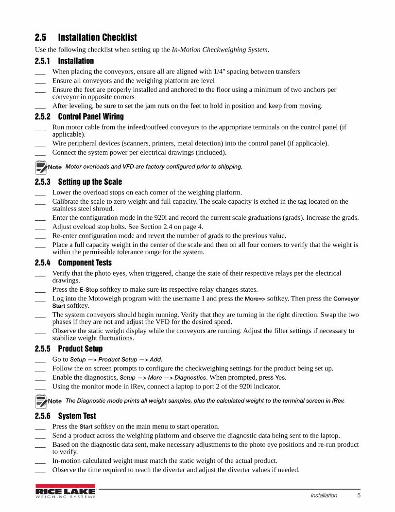
2.5 Installation ChecklistUse the following checklist when setting up the In-Motion Checkweighing System.
2.5.1 Installation___ When placing the conveyors, ensure all are aligned with 1/4'' spacing between transfers ___ Ensure all conveyors and the weighing platform are level___ Ensure the feet are properly installed and anchored to the floor using a minimum of two anchors per
conveyor in opposite corners___ After leveling, be sure to set the jam nuts on the feet to hold in position and keep from moving.
2.5.2 Control Panel Wiring___ Run motor cable from the infeed/outfeed conveyors to the appropriate terminals on the control panel (if
applicable).___ Wire peripheral devices (scanners, printers, metal detection) into the control panel (if applicable).___ Connect the system power per electrical drawings (included).
Motor overloads and VFD are factory configured prior to shipping.
2.5.3 Setting up the Scale___ Lower the overload stops on each corner of the weighing platform.___ Calibrate the scale to zero weight and full capacity. The scale capacity is etched in the tag located on the
stainless steel shroud.___ Enter the configuration mode in the 920i and record the current scale graduations (grads). Increase the grads. ___ Adjust oveload stop bolts. See Section 2.4 on page 4.___ Re-enter configuration mode and revert the number of grads to the previous value.___ Place a full capacity weight in the center of the scale and then on all four corners to verify that the weight is
within the permissible tolerance range for the system.
2.5.4 Component Tests___ Verify that the photo eyes, when triggered, change the state of their respective relays per the electrical
drawings.___ Press the E-Stop softkey to make sure its respective relay changes states.___ Log into the Motoweigh program with the username 1 and press the More=> softkey. Then press the Conveyor
Start softkey.___ The system conveyors should begin running. Verify that they are turning in the right direction. Swap the two
phases if they are not and adjust the VFD for the desired speed.___ Observe the static weight display while the conveyors are running. Adjust the filter settings if necessary to
stabilize weight fluctuations.
2.5.5 Product Setup___ Go to Setup —> Product Setup —> Add.
___ Follow the on screen prompts to configure the checkweighing settings for the product being set up.___ Enable the diagnostics, Setup —> More —> Diagnostics. When prompted, press Yes.___ Using the monitor mode in iRev, connect a laptop to port 2 of the 920i indicator.
The Diagnostic mode prints all weight samples, plus the calculated weight to the terminal screen in iRev.
2.5.6 System Test___ Press the Start softkey on the main menu to start operation.___ Send a product across the weighing platform and observe the diagnostic data being sent to the laptop.___ Based on the diagnostic data sent, make necessary adjustments to the photo eye positions and re-run product
to verify.___ In-motion calculated weight must match the static weight of the actual product.___ Observe the time required to reach the diverter and adjust the diverter values if needed.
Note
Note
Installation 5

3.0 ConfigurationThe softkeys and menus used to configure the In-Motion Checkweighing System are discussed in this section.
The scale sample rate must be set to 60 Hz. This is the default setting and should not be changed. A normally closed photo eye must be used.
3.1 SecurityUsers must log in to the IMC. The default login name is Admin and there is no password until one is specified by the user. Additional users can be added to the user database and assigned one of four security levels. Each increasing level of security includes access to all features and functionality for the lower security levels.
3.1.1 Login ProceduresWhen the 920i is powered on, Enter Login Name is displayed.
Home Cancel End
Enter Login Name:=>
Figure 3-1. Login Menu
1. Press the Up arrow. The character map is displayed.
2. Enter Admin using the indicator arrows to move the cursor to highlight the letters, then press to
add it to the prompt area.
If an incorrect letter is entered, press on the numeric keypad to delete the letter.
3. Once Admin displays in the prompt, press the Down arrow until the cursor moves to the final letter, as shown in Figure 3-2.
4. Press to finalize the login process.
Figure 3-2. Character Map
Security Level Authority
Operator Run products/view statistics; cannot access setup menu optionsSupervisor Set up products/run reports, see Section 3.3.1.6 on page 9Maintenance Set up system features/functions, see Section 3.3.1.8 on page 10Administrator Access to all menus plus user setup, see Section 3.3.1.12 on page 11
Table 3-1. Login Security Levels
Note
Note
Home Cancel End
=> Admin
A B C D E F G H I J K L M N O P Q R S T U V W X Y Z a b c d e f g h i j k l m n o p q r s t u v w x y z
Sp ! # $ & ? @ ( ) < > + - * % = / \ “ . , : ; ‘ ^ _ ` | ~ [ ] { }
6 In-motion Checkweighing System
3.1.2 User Setup - Administrator AccessTo setup users, access the main menu as the Administrator. A Setup softkey displays.
1. Press the Setup softkey to view the program menu.
2. Press the More => softkey until the Users softkey displays as a menu choice. Only administrators can access this feature. See Section 3.3.1.12 on page 11.
3. Press the Users softkey to access a list of users in the system.
• Press the Add softkey to enter the login name, password, and security level for a new user.
• Press the Edit softkey to change the password and security level for existing users.
• Press the Delete softkey to delete a user from the system. After logging out, the user is no longer be available.
• Press the Search softkey to enter a user name. If the user is found, it is displayed in the list. If it is not found, Login Name Not Found is displayed.
The Administrator user name cannot be deleted from the system and the Administrator’s security level cannot be changed. A strong password is recommended for the Administrator; use a password with a mix of characters and digits.
When editing a user, press on the 920i to keep the same security level currently assigned to them.
3.2 ProductsUse the following section to add, edit, delete and search products.
3.2.1 Adding a ProductWhen adding a product, the user is prompted to enter the product ID, product description, product tare weight, units of weight to use when weighing and the five zone ranges as either a percentage or weight value. After adding a product, use the Calibrate Product menu item to set up the weighing delay durations.
Add a product using the 920i display softkeys.
StartSelect
Product SetupStatistics More =>
Figure 3-3. 920i Main Menu
1. Press Setup softkey.
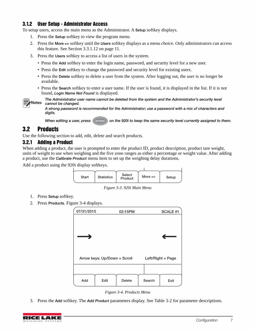
2. Press Products. Figure 3-4 displays.
Figure 3-4. Products Menu
3. Press the Add softkey. The Add Product parameters display. See Table 3-2 for parameter descriptions.
Notes
07/31/2015 02:15PM
Add
SCALE #1
Delete Exit
Arrow keys: Up/Down = Scroll Left/Right = Page
Edit Search
Configuration 7

Access the character map by pressing the UP arrow on the 920i display. If an incorrect letter or number is entered, press the CLR key.To exit the character map, use the down arrow key on the 920i display until cursor moves to the final letter. Press Enter.
EditTo edit a product description:
1. Press the Edit softkey.
2. Scroll through the menu choices using the down arrow and make appropriate edits.
3. If no edit is to be made to a particular parameter, press Enter to advance to the next parameter in the list.
DeleteTo delete a product,
1. Select product to be deleted.
2. Press the Delete softkey
3. Press Yes to delete.
SearchTo search for a product:
1. Press the Search softkey.
2. Enter the Product ID.
3. Press to access the product.
Parameter Description
ID Product ID – one to eight charactersDescription Product description – up to 20 characters. Can be numeric or alpha-numeric.Units Units of measure – primary, secondary or tertiary.Tare Weight System tare value while using the product in a run.TO2 Weights above this value will be considered to be in the TO2 range.
TO1Weights above this value and below TO2 will be considered to be in the high range. Set the value to the same as TO2 to disable this range.
Target Target weight – must be specified if the system tolerance type is either offset or percent.
TU1Weights below this value and above TU2 will be considered in the TU1 range. Set the value to the same as the TU2 value to disable this range.
TU2 Weights below this value will be considered to be in the TU2 range.
Adjust PercentAdjusts the weight of every item by a set percentage. Zero is recommended unless absolutely necessary. Example: If the system is consistently reading 10% low, adjust percent to 10% to compensate.
Reject Action Stop or divert for rejected projects.Reject Delay The delay (in milliseconds) after a product is weighed before turning on the reject diverter.Reject On Time The amount of time (in milliseconds) to engage the diverter.TO2 Reject If yes, the item is rejected if the weight falls in the TO2 range.TO1 Reject If yes, the item is rejected if the weight falls in the TO1 range. TU1 Reject If yes, the item is rejected if the weight falls in the TU1 range.TU2 Reject If yes, the item is rejected if the weight falls in the TU2 range.
Table 3-2. Product Parameters
Note
8 In-motion Checkweighing System

3.3 Menus and SoftkeysThe main menu consists of seven softkeys. Pressing the More=> softkey displays the last two softkeys.
ConveyorOn/Off
Logout More => Setup
Start Statistics SelectProduct
More => Setup
Press More=> to view other softkeys
Press More=> to return to previous softkeys
Figure 3-5. Main Menu 1
3.3.1 Setup SoftkeyPress the Setup softkey to access the Setup menu. This menu consists of seven sub-menus.
3.3.1.6 Supervisor Menus
Clear Statistics
ProgramVersion
SetTime/Date
More => Exit
Products Calibrate Product
Print Reports More => Exit
Press More=> to view more softkeys
Press More=> to return to previous softkeys
Figure 3-7. Setup Menu – Supervisor Parameters
Softkey Description
Start Press Start to begin the conveyor, the product is detected and weighed Statistics Displays product statistics, these statistics are updated in real time during the weighing process
Note: The standard deviation is calculated for at least the last 5000 productsSelect Product Product list, use the Up/Down arrows to highlight the desired product, then press Select Product.
A search for a product can also be done from this display by pressing the Search softkeyConveyor On/Off Starts and stops the weight conveyor, this does not checkweigh products crossing the scale sectionLogout Logs out of the systemMore=> Toggles between parametersSetup Enters the setup menu, not available to operators
Table 3-3. Main Menu Softkeys
Softkey Description
Products Accesses the product database list, products can be added, edited, deleted, or searchedCalibrate Product Allows the user to calibrate each product, Refer to Section 4.0 on page 12 for details on calibrationPrint Reports Allows the user to print a user, product, zone, or parameter report. See Section 5.0 on page 17Clear Statistics Clears all product statisticsProgram Version Displays the program versionSet Time/Date Used to set the time and date for the 920i More=> Accesses next parameter displayExit Returns to the main menu
Table 3-1. Supervisor Menu Softkeys
Configuration 9

3.3.1.8 Maintenance Menus
ToleranceSetup
OverrunSetup
DualPhoto eyes More => Exit
ConveyorSetup
ProductDetection
Reject Setup More => Exit
Figure 3-9. Setup Menu – Maintenance Parameters
Softkey Description
Conveyor Setup Allows the user to enter the start conveyor output. Changing this output could require changes in the 920i configuration file to set up digital I/O points
Product Detection
Allows the user to define the start data collection input, the stop data collection input, the maximum photo-eye on time (in milliseconds), photo eye alarm output, and photo eye alarm duration (in milliseconds)Setting the maximum photoeye On time to 0 disables the photo eye alarm featureChanging the inputs or output could require changes in the 920i configuration file to set up digital I/O points Flicker time is also set up under this parameter; it is the time in milliseconds (ms), that after a product has been detected, a new product cannot be detected
Reject Setup Allows the user to define the reject output as well as product defect input 1 and 2; changing the inputs or output could require changes in the 920i configuration file to set up digital I/O points
Tolerance Setup Allows the user to define the output relays that are used to indicate the 5 zone ranges for each product check weighed. Also, the out of tolerance alarm output, out of tolerance alarm duration, and zone type (by weight or by percent of target) are set hereNote: When editing the zone type, press Enter to keep the current value
Overrun Setup Allows the user to set the overrun photo eye input, the overrun alarm output and the overrun alarm duration Set the alarm duration to 0 to disable; if an overrun is detected, the overrun alarm signals the error, however the system will attempt to continue the weighing process
Single/Dual Photoeyes
Toggles from single photo-eye to dual photo-eyes; the displayed softkey is the number of photo eyes that will be used in the weighing processSingle photo eye starts data collection input only; dual photo eyes uses start and stop data collection as well as the overrun input, if enabledNote: The dual photo eyes are preferred method
More=> Accesses next parameter displayExit Returns the user to the main menu
Table 3-1. Maintenance Softkeys
10 In-motion Checkweighing System

3.3.1.10 General Parameters
ReqDefect Input 1 More => Exit
Prod. Data Format
QualityCheck Count
Stable ReadDivision
More => ExitStd Dev.Queue Lgth.
EtherNet IP
Auto Zero
More => ExitAuto-CalAdjustment
E-Stop Setup
Figure 3-11. General Setup Menus
3.3.1.12 Administrator Parameters
Users Diagnostics More => ExitTransmit Weights
Figure 3-13. Administration Menu
Softkey Description
E-Stop Setup Allows the user to set the E-Stop input; setting the input to 0 disables the featureChanging the input could require changes in the 920i configuration file to set up digital I/O points
Auto-Zero Enter a value to specify the auto-zero period (in milliseconds); it begins when the product is finished and can last until the next product reaches the photo eye; if there are drifting issues or trouble getting an accurate weighment use this feature to zero the scale between weighments
Auto-Cal Adjustment Fine tunes the delay before sample time and sample time settings; it does this by a percentage of the total sample time during the auto calibration of a single photo eye system Default rate is 20%, valid values 0-49%
EtherNet IP Allows the user to set the duration of the EtherNet IP output of Slot 0, Bit 1; set to 0 to disable Stable Read Division Allows the user to key in a value for the number of stable read divisions; default is 15
Note: It is not recommended to change this parameterStd Dev. Queue Lgth. The number of products included in the calculation of the standard deviationQuality Check Count Allows the user to define the number of consecutive products to divert during a quality checkRequire Defect Input 1 If set to Yes, a pulse on defect input 1 means the product is acceptable; if set to No, a pulse on defect
input 1 means the product is not acceptable and will be rejected.Product Data Format Allows the user to configure the real-time data string on port 3. This string can be customized using
tokens, delimiters or static text. See Section 7.2 on page 26 on page for further information.More=> Accesses Accesses next parameter displayExit Returns the user to the main menu.
Table 3-1. Setup Menu 5 Softkeys and Descriptions
Softkey Description
Users Accesses the user database list. Users can be added, edited, and deletedDiagnostics Allows the user to dump the weight samples from a weighment out of port 2,
done during setup or troubleshootingTransmit Weights If Yes, the custom serial string is sent out port 3 after each item is weighedMore=> Returns the supervisor parametersExit Returns the user to the main menu
Table 3-1. Administration Softkeys
Configuration 11
4.0 CalibrationTo calibrate the scale, run a sample product across the scale to see the distribution curve and set up the weighing parameters for each product. These parameters include sample delay and sample time.
By pressing Start, the conveyor begins and the photo-eye detects product. At the end of five seconds, the system alerts the user to the time at which the detection input was cleared. A graph is displayed showing the timing of the product weight across the five seconds. The user can then set the delay before sampling time and sample duration by viewing the graph weight and product detection details.
Calibrate each product individually. A normally closed photo eye must be used.
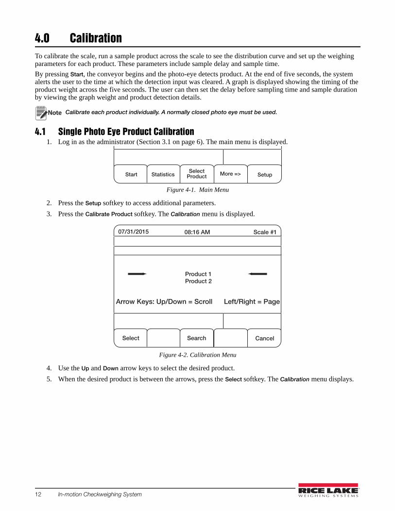
4.1 Single Photo Eye Product Calibration1. Log in as the administrator (Section 3.1 on page 6). The main menu is displayed.
Figure 4-1. Main Menu
2. Press the Setup softkey to access additional parameters.
3. Press the Calibrate Product softkey. The Calibration menu is displayed.
Figure 4-2. Calibration Menu
4. Use the Up and Down arrow keys to select the desired product.
5. When the desired product is between the arrows, press the Select softkey. The Calibration menu displays.
Note
StartSelect
Product SetupStatistics More =>
07/31/2015 08:16 AM
Select
Scale #1
Search Cancel
Arrow Keys: Up/Down = Scroll Left/Right = Page
Product 1Product 2
12 In-motion Checkweighing System

07/31/2015 08:17 AM
Start
Scale #1
SampleDuration Exit
Delay: 500 Duration: 300 Min. Detect 0
Delay BeforeSample
0 ms 1200 ms 2400 ms 3600 ms 4800 ms 6000 ms
Min. DetectDuration
Figure 4-3. Calibration Menu
07/31/2015 08:18 AM
Start
Scale #1
SampleDuration Exit
Delay: 500 Duration: 300 Min. Detect 0
Delay BeforeSample
0 ms 1200 ms 2400 ms 3600 ms 4800 ms 6000 ms
Detection at 2016 milliseconds
Min. DetectDuration
Item is entirely on scale
Item enters scale
Begin weight sample
Item leaves scale
End weight sample
The Delay Before Sample and Sample Duration softkeys should be used only for fine tuning after auto calibration. If an additional auto calibration is performed after these values are set, they are reset to zero.
6. Press the Start softkey to start auto calibration. The item moves past the photo-eye, across the belt and is auto calibrated. A graph is displayed showing the timing of the product weight across five seconds.
Figure 4-4. Distribution Curve Graph
7. If there is no End weight sample line or it is near the five second marker, the sample time may be too long. Move the product closer to the photo eye and perform another auto calibration. If this does not work, use the Sample Duration softkey to reduce the value.
Softkey Description
Start Begins in-motion calibration processDelay Before Sample
Amount of time (milliseconds) after an item completely passes the photo eye before weight is measured. This is useful if the photo-eye is mounted ahead of the belt.
Sample Duration Sample duration (milliseconds)Min. Detect Duration
Time (milliseconds), that photo eye must stay on in order to count as a product. If 0 is selected, the feature is disabled.
Exit Returns to main menu
Table 4-1. Calibration Screen Softkeys and Descriptions
Note
Calibration 13

07/31/2015 08:18 AM
Start
Scale #1
SampleDuration Exit
Delay Before Sampling: 1000 Sample Duration: 2000
Delay BeforeSample
0 ms 1000 ms 2000 ms 3000 ms 4000 ms 5000 ms
Detection at 2016 milliseconds
Min. DetectDuration
Delay before sampling begins
End weight sample
Begin weight sample
8. Set a delay before sample value (in milliseconds), if the photo eye is mounted ahead of the belt.
Figure 4-5. Distribution Curve With Delay Before Sampling
Once the graph displays a distribution curve representing the product entering and leaving the scale, calibration is successful.
4.1.1 Optimal Graph AdjustmentsThe distribution curve should be symmetrical; there should be an arc as the item enters the belt and an arc as it leaves. Figure 4-4 and Figure 4-5 show an arc as the product enters the belt, but not the full arc as the product leaves.
This still works, but it leaves little room for unexpected variables. Since the weighment is measured until the product is almost off the belt, it is more likely an inaccurate weighment could be made. Having the weight taken at the center of the distribution curve is preferred. Figure 4-6 is an example of an optimal distribution curve.
07/31/2015 08:18 AM
Start
Scale #1
SampleDuration Exit
Delay Before Sampling: 500 Sample Duration: 2000
Delay BeforeSample
0 ms 1000 ms 2000 ms 3000 ms 4000 ms 5000 ms
Detection at 1516 milliseconds
Min. DetectDuration
Item is entirely off scale
Figure 4-6. Optimal Distribution Curve
To achieve an optimal graph, fine-tuning of the delay before sample and/or sample time may be necessary. Once one of these values is set, the graph will refresh with the latest auto calibration displayed under the new parameters. Do not perform another auto calibration or any fine-tuning is reset to zero. Use the latest auto calibration and fine-tune, repeatedly if needed, until a symmetrical graph is displayed.
14 In-motion Checkweighing System

4.2 Calibrating a Product with Diagnostics Using Single or Dual Photo Eyes1. Log in as the Administrator.2. Press the Setup softkey.
3. Press the Diagnostics softkey.
Figure 4-7. Administration Menu
4. Press the Yes softkey to dump weight samples out Port 2 (9-pin serial port).
Once enabled, the 920i streams diagnostic weight information out of Port 2 each time a new product is detected. To view this data, use a straight through 9-pin serial cable to connect the 920i to a laptop with a terminal program like Hyperterminal or Procomm.
The default baud rate on port 2 should be set at 115200, N-8-1. Make sure to use the same settings on the terminal program. This can also be viewed using iRev by selecting the monitor mode under the communications tab.
For this process, it is recommended to use a single product for each of the steps, statically weighing the product before weighing in motion. The static weight and the in motion weight should be the same.
Press the Start softkey from the Main Menu. When a product passes over the scale and weighing is complete, the indicator sends the diagnostic data to the laptop.
Example of the diagnostic data is shown below.Sample Time: 650 millisecondsSamples: 64High Sample: 3.33Low Sample: 0.89Vibration: 2.44Weight Samples:
0.89 0.89 1.28 1.28 1.69 2.10 2.10 2.49 2.49 2.823.07 3.07 3.22 3.22 3.30 3.33 3.33 3.33 3.33 3.333.33 3.33 3.33 3.33 3.33 3.33 3.33 3.33 3.33 3.333.33 3.33 3.33 3.33 3.33 3.33 3.33 3.33 3.33 3.333.33 3.33 3.33 3.33 3.33 3.33 3.33 3.33 3.33 3.333.33 3.33 3.33 3.33 3.33 3.33 3.33 3.33 3.33 3.333.33 3.33 3.33 3.33
Calculated Weight: 2.38
Each weight sample taken in the time between the photo eye triggers can be viewed. In this case, the known product weighs 3.33 pounds, but the calculated weight is incorrect because the samples start off very light. This is an indication that the Start Data Collection Photo Eye has been placed too close to the entry of the scale (dual photo eye) or the Delay Before Sample time is too short (single photo eye) and is being triggered before the scale is supporting the entire weight of the product.
To correct this example, move the Start Data Collection Photo Eye closer to the end of the scale or slightly increase the Delay Before Sample time and run the same product again. The goal is to have the photo eyes in a position where all of the samples are equal.
Users Diagnostics More => ExitTransmit Weights
Note
Calibration 15

In some cases, it is necessary to move the Stop Data Collection Photo Eye (dual photo eye) or decrease the Sample Time (single photo eye).
The example below shows a diagnostic result that would indicate this:Sample Time: 500 MillisecondsSamples: 49High Sample: 3.33Low Sample: 0.12Vibration 3.21Weight Samples:
3.33 3.33 3.33 3.33 3.33 3.33 3.33 3.33 3.33 3.333.33 3.33 3.33 3.33 3.33 3.33 3.33 3.33 3.33 3.333.33 3.33 3.33 3.33 3.33 3.33 3.33 3.33 3.33 3.333.33 3.33 3.33 3.33 3.33 3.33 3.33 3.33 3.33 3.333.33 2.98 2.56 2.20 1.90 1.10 0.67 0.33 0.12
Calculated Weight: 3.12
The calculated weight is incorrect because the Stop Data Collection Photo Eye is being triggered or the Sample Time expires when the product is starting to be supported by the out feed conveyor. To fix this, move the Stop Data Collection Photo Eye closer to the entry of the scale or shorten the Sample Time.
For products running at a high rate of speed, the total number of samples can be as small as five. This is the minimum number of samples recommended.
The ideal result of diagnostics should be similar to the data below. Sample Time: 410 MillisecondsSamples: 41High Sample: 3.33Low Sample: 3.33Vibration: 0Weight Samples:
3.33 3.33 3.33 3.33 3.33 3.33 3.33 3.33 3.33 3.333.33 3.33 3.33 3.33 3.33 3.33 3.33 3.33 3.33 3.333.33 3.33 3.33 3.33 3.33 3.33 3.33 3.33 3.33 3.333.33 3.33 3.33 3.33 3.33 3.33 3.33 3.33 3.33 3.333.33
Calculated Weight: 3.33
Important
16 In-motion Checkweighing System
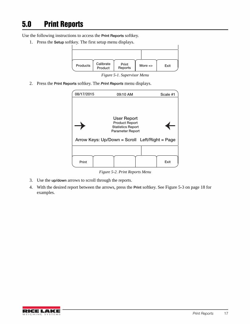
5.0 Print ReportsUse the following instructions to access the Print Reports softkey.
1. Press the Setup softkey. The first setup menu displays.
Figure 5-1. Supervisor Menu
2. Press the Print Reports softkey. The Print Reports menu displays.
Figure 5-2. Print Reports Menu
3. Use the up/down arrows to scroll through the reports.
4. With the desired report between the arrows, press the Print softkey. See Figure 5-3 on page 18 for examples.
Products CalibrateProduct
PrintReports
More => Exit
08/17/2015 09:10 AM
Scale #1
Exit
Arrow Keys: Up/Down = Scroll Left/Right = Page
User ReportProduct Report
Statistics ReportParameter Report
Print Reports 17

Figure 5-3. Report Examples
18 In-motion Checkweighing System

6.0 Option Card InstallationUse the following procedure to install option cards in the 920i.
Disconnect power to the indicator prior to removing the backplate.Use a wrist strap for grounding and protecting components from electrostatic discharge (ESD) when working inside the indicator enclosure.
1. Place indicator face down on an anti-static work mat.
2. Remove screws securing the backplate to the enclosure body.
3. Carefully align the option card connector with connector J5 or J6 on the 920i CPU board.
4. Press down firmly to seat the option card in the CPU board connector.
5. Using the screws and lock washers provided in the option kit, secure the other end of the option card to the standoffs on the CPU board.
Figure 6-1. Install Option Card
6. Make connections to the option card as required.
• See Section 6.1 on page 20 for the Memory Expansion Card• See Section 6.2 on page 21 for the Digital I/O card• See Section 6.3 on page 22 for the Single-Channel A/D Card
7. Use cable ties to secure loose cables inside the enclosure.
WARNING
J5
J6
Single-Channel A/D Card
J6
J6
Digital I/O Card
Memory Expansion Card
Option Card Installation 19

6.1 Memory Expansion Card
J1
1
6Battery
Figure 6-2. Memory Expansion Card
Periodically check the battery voltage on installed memory option cards. Batteries should be replaced when the battery voltage falls to 2.2 VDC. Life expectancy of the battery is 10 years.
Note All database information stored on a memory card is lost if the memory card battery fails.
CAUTIONThere is a risk of explosion if the battery is replaced with an incorrect type. Dispose of batteries per manufacturer instruction.
Specifications1 MB, non-volatile SRAM with supervisory write protection3 V high-density lithium battery
20 In-motion Checkweighing System

6.2 Digital I/O Expansion CardA digital I/O expansion card installed on connector J5 of the CPU board, is configured as slot 1. A card installed at connector J6 is configured as slot 2.
Figure 6-3 shows connections available on the Digital I/O option card connector J3 (up to eight digital I/O channels). Connector J2 provides all 24 channels using a 50-pin ribbon cable (Table 6-1).
GN
D
J3
DIO
1
DIO
3
DIO
4
+5V
+5V
DIO
5
DIO
6
DIO
7
DIO
8
GN
D
DIO
2
1
50
J2
J1
1 12
49
2
Figure 6-3. Digital I/O Expansion Card Use the DIG I/O menu to configure digital I/O as necessary. See the 920i manual (PN 67887) for more information.
SpecificationsI/O Channels Up to 24, 5 V/TTL, each software configurable as input or outputRelay Supply Voltage 5 VDC, 1 A maximumInput Voltage 0–5.5 V maximumDigital Outputs 24 mA balanced outputs with sink/source capabilityInput Protection 8-screw terminal: 300 W transient voltage suppression for ESD, EFT (electrical fast transients), tertiary
lightning, and system-generated transients per IEC 60001-4-2, 60001-4-4, and 60001-4-5; European Standards EN50082 and EN61000-4Remaining I/O: 2 KV HBM, 100 V machine model
I/O Connection 50-pin ribbon connector, 8-screw terminal connector
Pin Signal Pin Signal
1 DIO24 27 DIO113 DIO23 29 DIO105 DIO22 31 DIO97 DIO21 33 DIO89 DIO20 35 DIO7
11 DIO19 37 DIO613 DIO18 39 DIO515 DIO17 41 DIO417 DIO16 43 DIO319 DIO15 45 DIO221 DIO14 47 DIO123 DIO13 49 +5V25 DIO12 even pins GND
Table 6-1. Ribbon Cable Connections
Option Card Installation 21

6.3 Single-Channel A/D Card Installation
SIG
+
SIG
– S
EN
+
SE
N–
EXC
+
EXC
–
J1JP2JP1
Figure 6-4. Single-Channel A/D Card
1. To attach cables from load cells or junction boxes to the A/D card, route the cables through the cord grips and wrap the shield wires around the ground stud on the enclosure.
2. Secure shield wires to the ground stud with the kep nut included in the parts kit.See the 920i installation manual (PN 67887) for more information about grounding cables.
3. Remove connector from J1 on the A/D card. Wire the load cell cable from the load cell or junction box to connector J1 as shown in Table 6-2.
4. If using 6-wire load cell cable (with sense wires), remove jumpers JP1 and JP2 before reinstalling connector J1. For 4-wire installation, leave jumpers JP1 and JP2 on.
5. When connections are complete, reinstall the load cell connector on the A/D card and use cable ties to secure the load cell cable to the inside of the enclosure.
SpecificationsExcitation Voltage 10 ± 0.5 VDC,
16 x 350 or 32 x 700 load cells per A/D cardSense Amplifier Differential amplifier with
4- and 6-wire sensingAnalog Signal Input Range –10 mV/V to +70 mV/V
Analog Signal Sensitivity 0.3 V/grad minimum @ 7.5 Hz
1.0 V/grad typical @ 120 Hz
4.0 V/grad typical @ 960 HzA/D Sample Rate 7.5–960 Hz, software selectable
Input Impedance >35 M typicalInternal Resolution 8 000 000 counts Wt Display Resolution 9,999,999Input Sensitivity 10 nV per internal countSystem Linearity ±0.01% of full scaleZero Stability ±150 nV/°C, maximumSpan Stability ± 3.5 ppm/°C, maximumInput Voltage Differential ±800 mV referenced to earth groundInput Overload Load cell signal lines ±10 V continuous, ESD protectedRFI/EMI Protection Signal, excitation, and sense lines protected
J1Connector Pin Function
1 +SIG2 –SIG3 +SENSE4 –SENSE5 +EXC6 –EXC
For 6-wire load cell connections, remove jumpers JP1 and JP2.
Table 6-2. A/D Card Pin Assignments
22 In-motion Checkweighing System

6.4 Close EnclosureOnce cabling is complete, the backplate needs to be reinstalled.
1. Ensure no excess cable is left inside the enclosure and tighten cord grips.
2. Position the backplate over the enclosure and reinstall the backplate screws.
3. Use the torque pattern shown in Figure 6-5 to prevent distorting the backplate gasket.
4. Torque screws to 15 inch-lb (1.7 N-m).
5. Reconnect power to the indicator.
The indicator automatically recognizes all installed option cards when it is powered on. No hardware-specific configuration is required to identify the newly installed card to the system.
1
3
5
14
17
16 12
9
8
7
10
11
18
15
4
2
6
13
Torque backplate screwsto 15 in- lb (1.7 N-m)
Figure 6-5. 920i Enclosure Backplate
Option Card Installation 23

7.0 Database/Communication
7.1 Database Tables and Stored VariablesThe following tables list the variables specified for the user database, product database and user activity database. All data is stored in the PC database.
Field Type Description
Name String User login namePassword String User password
SLevel String
User security level1 Operator2 Supervisor3 Maintenance4 Administrator
Table 7-1. User Database Variables (100 Record Maximum)
Field Type Description
Name String User login nameTime String Event timestampEvent String Event description
Table 7-2. User Activity Database (500 Record Maximum)
Field Type Description
ID String (8) Product IDDesc String (20) Product descriptionTare Real Product tare weight (container weight, if weighed with product)TO2 Real TO2 Weight or Percentage of TargetTO1 Real TO1 Weight or Percentage of TargetTarget Real Product target weightTU1 Real TU1 Weight or Percentage of TargetTU2 Real TU2 Weight or Percentage of TargetUseUnits String (10) Units to UseDBSample Integer Delay before sampling (single photo eye mode)SampleTrn Integer Sample duration (single photo eye mode)TO2Dvrt String Yes to divert products in this weight categoryTO1Dvrt String Yes to divert products in this weight categoryTU1Dvrt Stringr Yes to divert products in this weight categoreTU2Dvrt Stringr Yes to divert products in this weight categoreProdID String (8) Product IDAdjust Real Product adjustment valueRjctActn String (7) Stop or divert selection for rejected productRjctDely Integer Reject delayRjctOT Integer Reject output on timeMinDet Integer Minimum detection periodFlickTm Integer Flicker time
Table 7-3. Product Database Variables (1000 Record Maximum)
24 In-motion Checkweighing System
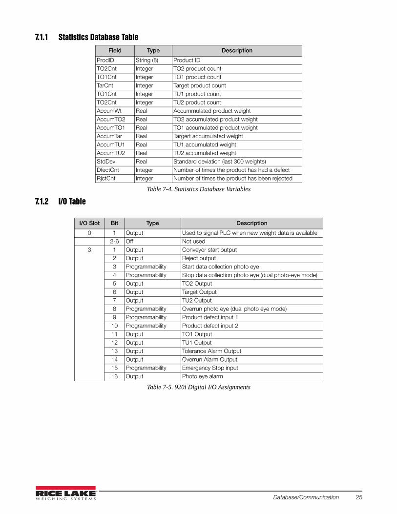
7.1.1 Statistics Database Table
7.1.2 I/O Table
Field Type Description
ProdID String (8) Product IDTO2Cnt Integer TO2 product countTO1Cnt Integer TO1 product countTarCnt Integer Target product countTO1Cnt Integer TU1 product countTO2Cnt Integer TU2 product countAccumWt Real Accummulated product weightAccumTO2 Real TO2 accumulated product weightAccumTO1 Real TO1 accumulated product weightAccumTar Real Targert accumulated weightAccumTU1 Real TU1 accumulated weightAccumTU2 Real TU2 accumulated weightStdDev Real Standard deviation (last 300 weights)DfectCnt Integer Number of times the product has had a defectRjctCnt Integer Number of times the product has been rejected
Table 7-4. Statistics Database Variables
I/O Slot Bit Type Description
0 1 Output Used to signal PLC when new weight data is available2-6 Off Not used
3 1 Output Conveyor start output2 Output Reject output3 Programmability Start data collection photo eye4 Programmability Stop data collection photo eye (dual photo-eye mode)5 Output TO2 Output6 Output Target Output7 Output TU2 Output8 Programmability Overrun photo eye (dual photo eye mode)9 Programmability Product defect input 1
10 Programmability Product defect input 211 Output TO1 Output12 Output TU1 Output13 Output Tolerance Alarm Output14 Output Overrun Alarm Output15 Programmability Emergency Stop input16 Output Photo eye alarm
Table 7-5. 920i Digital I/O Assignments
Database/Communication 25
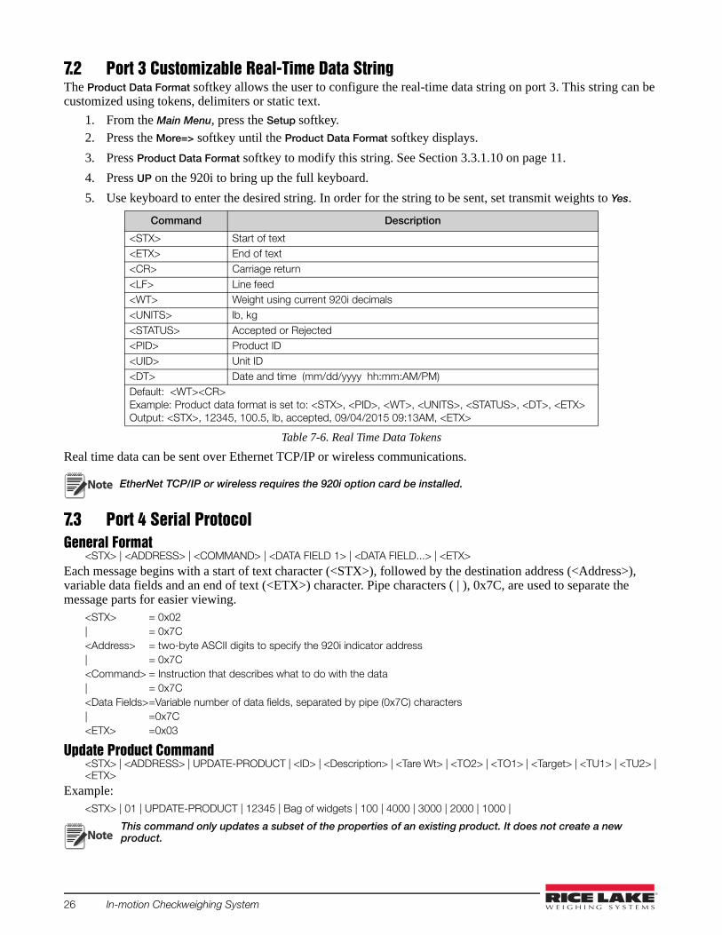
7.2 Port 3 Customizable Real-Time Data StringThe Product Data Format softkey allows the user to configure the real-time data string on port 3. This string can be customized using tokens, delimiters or static text.
1. From the Main Menu, press the Setup softkey.2. Press the More=> softkey until the Product Data Format softkey displays.
3. Press Product Data Format softkey to modify this string. See Section 3.3.1.10 on page 11.
4. Press UP on the 920i to bring up the full keyboard.
5. Use keyboard to enter the desired string. In order for the string to be sent, set transmit weights to Yes.
Real time data can be sent over Ethernet TCP/IP or wireless communications.
EtherNet TCP/IP or wireless requires the 920i option card be installed.
7.3 Port 4 Serial ProtocolGeneral Format
<STX> | <ADDRESS> | <COMMAND> | <DATA FIELD 1> | <DATA FIELD...> | <ETX>
Each message begins with a start of text character (<STX>), followed by the destination address (<Address>), variable data fields and an end of text (<ETX>) character. Pipe characters ( | ), 0x7C, are used to separate the message parts for easier viewing.
<STX> = 0x02| = 0x7C<Address> = two-byte ASCII digits to specify the 920i indicator address| = 0x7C<Command> = Instruction that describes what to do with the data| = 0x7C<Data Fields>=Variable number of data fields, separated by pipe (0x7C) characters| =0x7C<ETX> =0x03
Update Product Command<STX> | <ADDRESS> | UPDATE-PRODUCT | <ID> | <Description> | <Tare Wt> | <TO2> | <TO1> | <Target> | <TU1> | <TU2> | <ETX>
Example:<STX> | 01 | UPDATE-PRODUCT | 12345 | Bag of widgets | 100 | 4000 | 3000 | 2000 | 1000 |
This command only updates a subset of the properties of an existing product. It does not create a new product.
Command Description
<STX> Start of text<ETX> End of text<CR> Carriage return<LF> Line feed<WT> Weight using current 920i decimals<UNITS> lb, kg<STATUS> Accepted or Rejected<PID> Product ID<UID> Unit ID<DT> Date and time (mm/dd/yyyy hh:mm:AM/PM)Default: <WT><CR>Example: Product data format is set to: <STX>, <PID>, <WT>, <UNITS>, <STATUS>, <DT>, <ETX>Output: <STX>, 12345, 100.5, lb, accepted, 09/04/2015 09:13AM, <ETX>
Table 7-6. Real Time Data Tokens
Note
Note
26 In-motion Checkweighing System

Select Product Command<STX> | <Address> | SELECT-PRODUCT| <ID> | <ETX>
Example:<STX> | 01 | SELECT-PRODUCT | 12345 | <ETX>
A product can be run by stopping the current product (if necessary), selecting a new product, then starting the system.
Start Product Command<STX> | <Address> | STOP | <ETX>
Example:
<STX> | 01 | START| <ETX>
Stop Product Command<STX> | <Address> | STOP | <ETX>
Example:
<STX> | 01 | STOP | <ETX>
ACK/NAK ResponsesEach command sent from the PC is acknowledged by the 920i with an ACK or NAK response. Data sent from the indicator to the PC does not require an ACK or NAK response to the indicator.
<STX> | <Address> | <ACK> | <ETX>
or
<STX> | <Address> | <NAK> | <Reason for failure> | <ETX>
If the PC receives a NAK response, the reason for failure can be displayed by the user. The reason for failure text is also displayed at the indicator.
7.4 Fieldbus Protocol Slot 4 of the 920i is available for a Fieldbus IP option. This gives the 920i the ability to communicate with a PLC. In order for this communication, setpoints are used to store real time product data. Also an output is fired each time new product data is available for the PLC. This output duration can be configured to allow the flexibility to accommodate both fast and slow processing PLCs. This is done using the EtherNet IP® softkey on setup menu 6.
Each time a product is successfully weighed its information is stored into Gross setpoints.
* Setpoint values are numbers, the time values are formatted as HHMMSS on a 24 hours basis.
• 1 AM displays as 10000 • midnight displays as 0. • 3:15:15 PM displays as 151515.
Slot 0, Bit 1 will be fired each time the product data is updated in the setpoints signaling the PLC to retrieve the data.
Setpoint Number Description
97 Weight98 Time*99 1 for Accepted, 0 for Rejected
Table 7-7. Setpoint Values
Database/Communication 27

7.4.1 PLC Fieldbus Output to the 920i PLC fieldbus output to the 920i to monitor the input and read the setpoint value.
7.4.2 Response to Command 320With the following example of 800.5 lb checkweighed on the scale.
The PLC monitors Input 2, bit #3 when it is set to a 1. The PLC grabs the weight values in input 3 and 4. The values in input 3 and 4 are in IEEE floating point notation.
Outputs Description
1 320 - command to read setpoint2 97 - setpoint number to read3 04 0
Table 7-8. Fieldbus Output Commands
Input Description
1 320 - command echoed back2 16712 - batch status containing the output slot 0, bit 1
as bit #3 of this value.Binary = 0100000101001000
3 17480 - MSW4 8192 - LSW
Table 7-9. Fieldbus Response Commands
28 In-motion Checkweighing System

8.0 Maintenance/Troubleshooting
8.1 Preventive MaintenanceTo maximize performance of the In-Motion Checkweighing System (IMC) a few simple steps will help extend the life of the product and maintain performance.
Start of Shift• Photo eyes and reflectors must be kept clean and free of debris • Ensure photo eyes are properly aligned for optimum scale performance• Check the calibration of the scale using test weights • Check scale overloads to ensure they are set properly if the system weight verification fails
Weekly• Grease all bearings on the conveyor system. (frequency will vary depending on use)
Monthly• Check the belt tension and alignment of the conveyors periodically to ensure maximum scale and conveyor
performance. Belt tension can be adjusted on the idler end if needed• Check the set screws in the sprockets• Check drive timing belt tensions• Backup configuration and database information using iRev. (frequency of backup depends on frequency of
changes to configuration files and the addition of new files)Not all conveyor equipment systems are wash-down rated. Even in those that are, extreme water pressure should be avoided around the electrical components of the unit and the load cells.
8.2 TroubleshootingTable 8-1 lists general troubleshooting tips for various hardware error conditions.
Problem Cause Remedy
Load cell is reading a negative weight
Overload stops are touching the scale Adjust the overload stopsBinding on the scale Remove any outside factors in contact with the scaleLoad cell is faulty Replace the load cell
Load cell is drifting Needs recalibration Recalibrate the load cellLoad cell is faulty Replace the load cell
Program does not detect a product
Photo eyes do not have power (green light is off) Wire cable correctly, replace the cable, replace the photo eye, replace the 24V power supply
Photo eyes do not change state (orange light) Photo eye is dirty, the reflector is dirty, the photo eye is not in line with the reflector
Input relay does not change state Wire the cable correctly, replace the cable, replace the input relay
Program does not detect the input I/O is set incorrectly, new 920i program, replace 50 pin cable, replace 24 channel digital I/O card
Program detects a product but displays a zero weight
Program is set to single photo eye, not dual Press the softkey in the Setup Menu to select DualFor a single eye system, Delay Before Sample or Sample Duration is not set correctly
Under the Calibrate Product softkey, change timing
Filtering is set too high Change the 920i filtering settingsPhoto eyes are not in the correct position Adjust the photo eyesProgram is marking the product as a defect Change Require Defect Input 1 to no
Program is displaying a weight that is a too low
Photo eyes are not in the correct position Use diagnostic photo eyesFiltering is set too high Adjust the filteringFor a single eye system, Delay Before Sample or Sample Duration is not set correctly
Under the Calibrate Product softkey, change timing
Program is not getting consistent weights
Filtering is set too low Adjust the filteringToo much vibration in the system Remove any outside factors that could affect the
scale (fans, forklift traffic, etc)Products are spaced too close together Correct product spacing
Table 8-1. Troubleshooting Tips
Note
Maintenance/Troubleshooting 29

8.3 Photo Eye Troubleshooting
Indicator lights up andprogram is running
Is the green photo eyelight on? Wire cable correctly
Is the cablewired correctly?
Replace cableIs there 24 V across
+24 and -24?
Replace photo eye
Replace 24 Vpower supply
Is the orangephoto eyelight on?
Clean photo eyeand reflector Is photo eye set
to dark mode?
Set photo eye todark mode
Adjust thesensitivity
potentiometer
Is photo eyesensitivity control
set correctly?
Adjust eye orreflector sophoto eye is
reflecting
Is photo eyereflecting off the
reflector
Replace photo eye
Flag photo eye,does the
orange lightcome on? Adjust the
sensitivitypotentiometer
Is photo eyesensitivity control
set correctly?
Replace photo eye
Apply power to system
No
No
No
YesYes
Yes
Yes
Yes
Yes
Yes
Yes
No
No
No
No
No
Yes
Continued on Figure 8-2 on page 31
Figure 8-1. Photo Eye Troubleshooting Diagram – Page 1
30 In-motion Checkweighing System

Is the cable wired correctly?
Does the inputrelay turn on
in panel? Wire cablecorrectly
Is the e-stoppressed?
Release e-stop
Does theprogram seea product?
YesYesYes
No
Replaceinput relay
No
No
Is the 50 pin cable connected
at both ends?Plug in Cable
Set I/O
Yes
Yes
No
No
Is the I/O setcorrectly inprogram?
No
Replace 24 channelDI/O card
Replace 50pin cable
If system is not gettingan accurate weight seebasic troubleshooting
See Section 8.2 on page 29
Continued from Figure 8-1 on page 30
Figure 8-2. Photo Eye Troubleshooting Diagram – Page 2
Maintenance/Troubleshooting 31

32 In-motion Checkweighing System


230 W. Coleman St. • Rice Lake, WI 54868 • USAU.S. 800-472-6703 • Canada/Mexico 800-321-6703 • International 715-234-9171 • Europe +31 (0)26 472 1319
Rice Lake Weighing Systems is an ISO 9001 registered company. © Rice Lake Weighing Systems Specifications subject to change without notice.
www.ricelake.com
December 30, 2016 PN 108790 Rev B