in situ & 4d science - zeiss · pdf filein situ & 4d science ... date: july 2013 since...
TRANSCRIPT
Technical Note
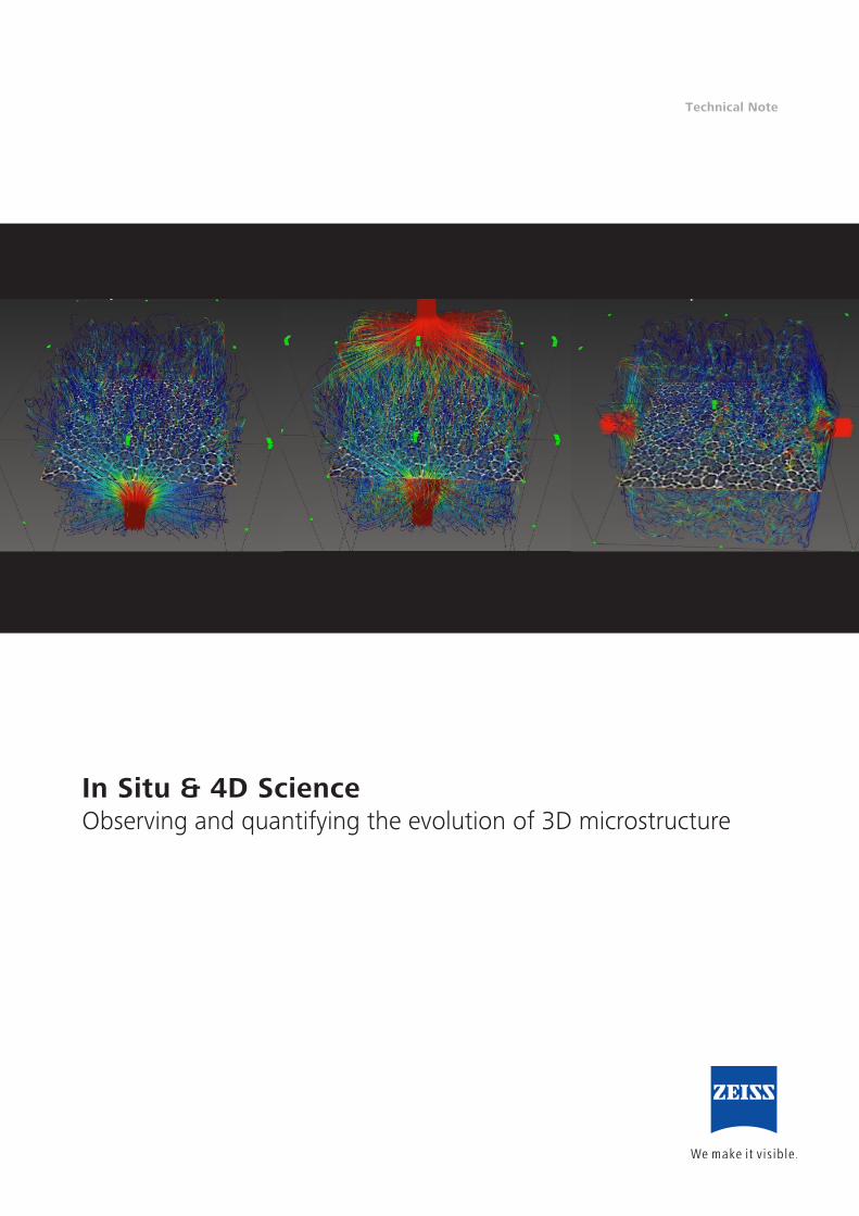
In Situ & 4D ScienceObserving and quantifying the evolution of 3D microstructure
Technical Note
2
In Situ & 4D ScienceObserving and quantifying the evolution of 3D microstructure
Author: Carl Zeiss Microscopy GmbH, Germany
Date: July 2013
Since the advent of the microscope, engineers and scientists have refined imaging techniques to observe 2D and
3D microstructures and quantify evolution over time, or resulting from stimuli such as temperature, force, etc.
The vast major ity of characterization techniques require samples to be destructively cut or consumed so that
they could not be observed under realistic conditions over time.
ZEISS 3D X-ray microscopes (XRM) are uniquely suited to
image materials in situ under variable environments in 4D
(3D plus time) in order to non-destructively characterize
and quantify the evolution of 3D microstructures. From
mechanical materials testing to carbon sequestration
investigations, innovative ZEISS features such as Dual
Scan Contrast Visualizer (DSCoVer) and Automated Filter
Changer facilitate a broad range of in situ research and
discovery.
A new materials science has emerged in which samples are
analyzed “in situ” to facilitate essential characterization of
performance under relevant operating or environmental
conditions. Measuring critical micro structural variation
(e.g., pore size, crack propagation) in the same sample
advances R&D scientific investigations and material reliability
improvements by evaluating the impact of varying levels of:
• Tensile or compressive stress • Pressure
• Temperature • Chemical environment
• Electrical bias • Gas or fluid flow
The non-destructive nature of X-ray microscopy is uniquely
suited to studying materials in situ under variable environ-
ments with controlled conditions over time (4D). ZEISS’s
unique “resolution at a distance” (RaaD) architecture
and In Situ Interface Kit deliver the highest performance
in situ 3D XRM characterization, maintaining high imaging
resolution as the distance between the X-ray source and
sample increases within in situ rigs. Overcoming the
resolution limits of conven tional micro-CT, Xradia Versa
ensure peak performance.
Enabling New Discoveries
Continuing to push the limits for scientific advancement,
ZEISS has emerged as the industry’s leader for in situ solu-
tions, enabling the use of the widest variety of rigs, from
high pressure flow cells to tension, compression and thermal
stages. Conducting in situ studies at submicron resolution in
3D enables unprecedented capabilities for a diverse range of
investigations essential for new discoveries in:
• 4D microstructural evolution: to non-destructively
determine the effect of en vironmental, stressed or real
operating conditions on microstruc ture over time with
samples repeatedly imaged to observe developments
critical to material performance: crack propagation,
corrosion or grain growth critical, etc.
• Failure analysis studies: to inspect semiconductor chips
that appear structurally intact upon manufacture but can
reveal weak interfaces under thermal stresses that may
crack or de form under the heat of operation
• Iteration between physical experiments and computational
models: to assess changes in structural evolution as samples
with complex 3D pore pathways become permeated by
fluid or gas, or experience temperature and compression
changes. These changes can be correlated and iterated
with finite element analysis models for 3D microstructure
and even external stress or flow models
• In operando or under operation device studies:
to understand aging and failure mechanisms in order
to improve production processes for devices such as s
emiconductor packages under electrical bias or batteries
and fuel cells during energy conversion
Technical Note
3
Why ZEISS
Spatial resolution, image contrast, and working distance
are all key parameters characterizing the performance of
anX-ray micro scope. ZEISS has leveraged technol ogy from
its synchrotron heritage to revolutionize research with
laboratory-based X-ray microscopy. Xradia Versa routinely
demonstrate superior imaging performance (<700 nm
spatial resolution, <70 nm voxels) compared to conventional
laboratory- and synchrotron-based micro-CT solutions. Tunable
propagation phase contrast, compositional contrast and
absorption contrast on the submicron scale help to achieve
superior results for imaging low-Z materials.
ZEISS in situ solutions solve the resolution and sample
load issues of micro-CT to deliver robust stages with load
capacities up to 15 kg and is the only X-ray solution able
to maintain submicron resolution within larger chambers.
An innovative Dual Scan Contrast Visualizer (DSCoVer)
allows flexible side-by-side tuning of two distinct tomogra-
phies for features normally indistinguishable within a single
scan, while Automated Filter Changer capabilities enhance
workflow efficiency.
Application Examples
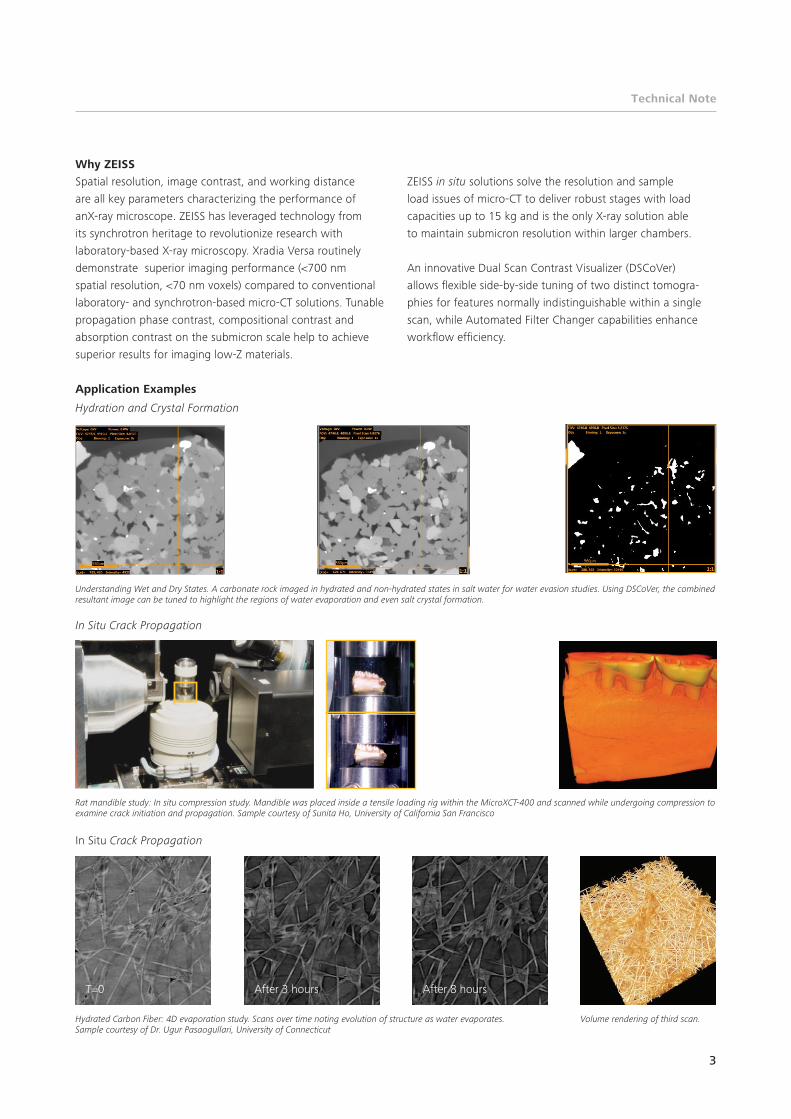
Hydration and Crystal Formation
In Situ Crack Propagation
In Situ Crack Propagation
Understanding Wet and Dry States. A carbonate rock imaged in hydrated and non-hydrated states in salt water for water evasion studies. Using DSCoVer, the combined resultant image can be tuned to highlight the regions of water evaporation and even salt crystal formation.
Rat mandible study: In situ compression study. Mandible was placed inside a tensile loading rig within the MicroXCT-400 and scanned while undergoing compression to examine crack initiation and propagation. Sample courtesy of Sunita Ho, University of California San Francisco
Hydrated Carbon Fiber: 4D evaporation study. Scans over time noting evolution of structure as water evaporates. Sample courtesy of Dr. Ugur Pasaogullari, University of Connecticut
Volume rendering of third scan.
T=0 After 3 hours After 8 hours
Technical Note
4
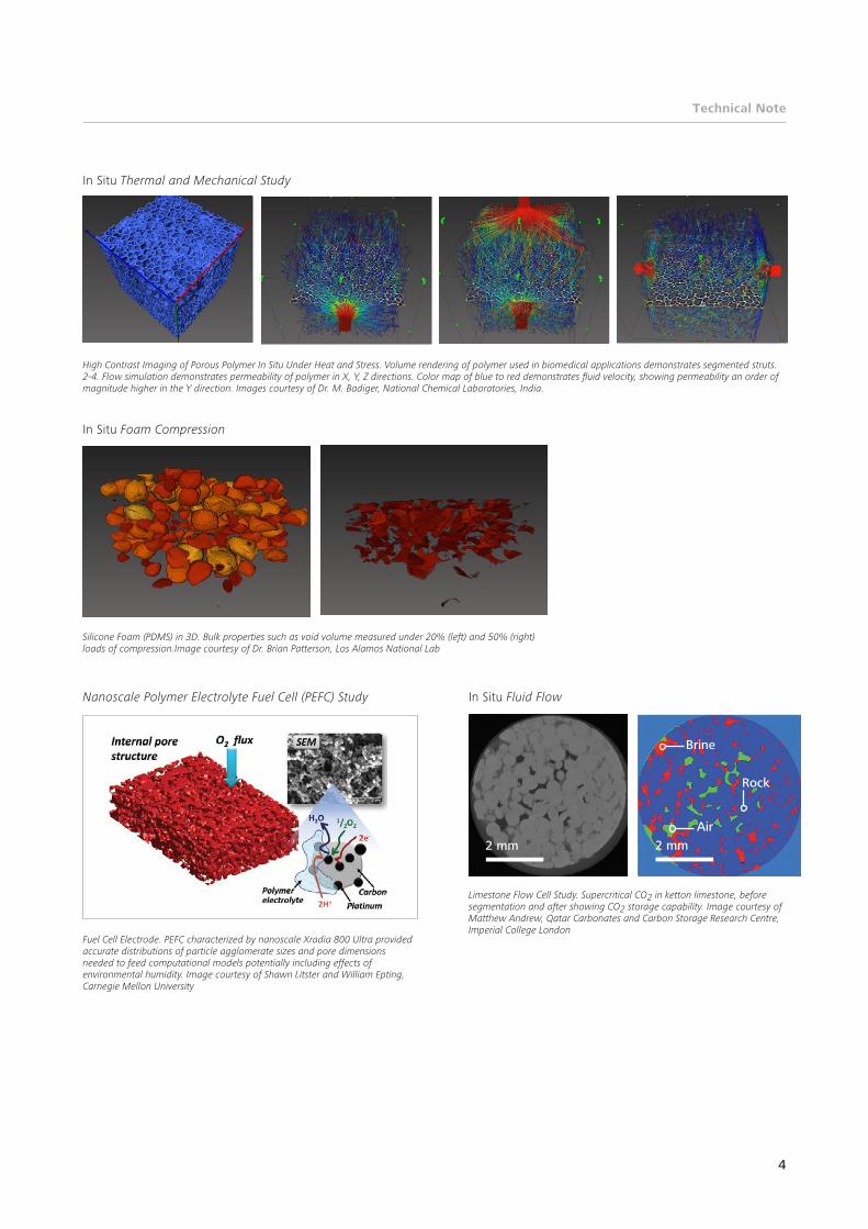
In Situ Thermal and Mechanical Study
In Situ Foam Compression
Nanoscale Polymer Electrolyte Fuel Cell (PEFC) Study In Situ Fluid Flow
High Contrast Imaging of Porous Polymer In Situ Under Heat and Stress. Volume rendering of polymer used in biomedical applications demonstrates segmented struts. 2-4. Flow simulation demonstrates permeability of polymer in X, Y, Z directions. Color map of blue to red demonstrates fluid velocity, showing permeability an order of magnitude higher in the Y direction. Images courtesy of Dr. M. Badiger, National Chemical Laboratories, India.
Silicone Foam (PDMS) in 3D. Bulk properties such as void volume measured under 20% (left) and 50% (right) loads of compression.Image courtesy of Dr. Brian Patterson, Los Alamos National Lab
Fuel Cell Electrode. PEFC characterized by nanoscale Xradia 800 Ultra provided accurate distributions of particle agglomerate sizes and pore dimensions needed to feed computational models potentially including effects of environmental humidity. Image courtesy of Shawn Litster and William Epting, Carnegie Mellon University
Limestone Flow Cell Study. Supercritical CO2 in ketton limestone, before segmentation and after showing CO2 storage capability. Image courtesy of Matthew Andrew, Qatar Carbonates and Carbon Storage Research Centre,Imperial College London
2 mm
Rock
Brine
Air
2 mm
Technical Note
Suggested Reading:
Nelson, J. et al. In Operando X-ray diffraction and transmission X-ray microscopy of lithium sulfur batteries. J. Amer. Chem. Soc. 134, 6337 (2012).
Naveh, G. R. S., et al. Tooth periodontal ligament: Direct 3D microCT visualization of the collagen network and how the network changes when the tooth is loaded. J. Struct. Biology 181, 108 (2013).
Patterson, B. M., et al. Measure of morphological and performance properties in polymeric silicone foams by X-ray tomography. J. Mat. Sci. 48, 1986 (2013).
Knight, S. P., et al. The study of intergranular corrosion in aircraft aluminum alloys using X-ray tomography. Corrosion Science 53, 727 (2011).
Escobedo, J. P. et al. Effects of grain size and boundary structure on the dynamic tensile response of copper. J. App. Phys. 110, 033513 (2011).
Carl Zeiss Microscopy GmbH 07745 Jena, Germany BioSciences and Materials [email protected] www.zeiss.com/xrm
EN_4
2_01
1_07
8 | C
Z 07
-201
3 | D
esig
n, s
cope
of
deliv
ery
and
tech
nica
l pro
gres
s su
bjec
t to
cha
nge
with
out
notic
e. |
© C
arl Z
eiss
Mic
rosc
opy
Gm
bH
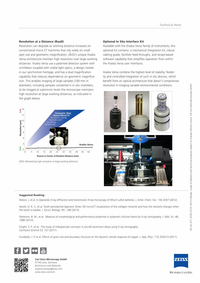
Resolution at a Distance (RaaD)
Resolution can degrade as working distance increases on
conventional micro-CT machines that rely solely on small
spot size and geometric magnification. ZEISS’s unique Xradia
Versa architecture maintain high resolution over large working
distances. Xradia Versa use a patented detector system with
scintillator coupled with visible light optics, a design rooted
in our synchrotron heritage, and has a dual magnification
capability that reduces dependence on geometric magnifica-
tion. This enables imaging of large samples (100 mm in
diameter), including samples contained in in situ chambers,
to be imaged at submicron levels the microscope maintains
high resolution at large working distances, as indicated in
the graph below.
Optional In Situ Interface Kit
Available with the Xradia Versa family of instruments, this
optional kit contains: a mechanical integration kit, robust
cabling guide, facilities feed-throughs, and recipe-based
software capability that simplifies operation from within
the Xradia Versa user interfaces.
Xradia Versa combine the highest level of stability, flexibil-
ity and controlled integration of such in situ devices, which
benefit from an optical architecture that doesn’t compromise
resolution in imaging variable environmental conditions.
ZEISS: Maintaining high resolution at large working distances
Source to Center of Rotation Distance (mm)
Res
olut
ion
(µm
)Lo
wH
igh
Geometric Mag Based MicroCTs Resolution rapidly degrades with increasing sample size
14
12
10
8
6
4
2
00 5 10 15 20 25 30 35 40 45 50