in situ measurement and numerical analysis on tunnel ...h25)_eurotun2013… · in-situ measurement...
TRANSCRIPT

EURO:TUN 2013
3rd International Conference on Computational Methods in Tunneling and Subsurface Engineering Ruhr University Bochum, 17-19 April 2013
191
In-situ Measurement and Numerical Analysis on Tunnel
Lining and Ground Behaviour due to Shield Excavation
Takahiro Konda1, Junichi Nagaya1, Tadashi Hashimoto1,
Hossain M. Shahin2 and Teruo Nakai2 1Geo-Research Institute, Japan 2Nagoya Institute of Technology, Japan
Abstract
In urban tunnelling, often construction is done under some constrained conditions. In
this paper, the ground movement due to shield excavation is observed and some
measurements of the first tunnel lining pressure and stress development due to the
excavation of second shield tunnel close to the first tunnel are carried out. The
influence of the construction loads due to shield tunnelling on the surrounding ground
and nearby structures is discussed. Numerical analysis is also carried out with elasto-
plastic constitutive model of soil in which the mechanical characteristic of ground
material and the construction process are appropriately taken into consideration.
Comparing the results of the analyses with the monitoring data, the behaviour of
surrounding ground and existing structure due to shield excavation is investigated
focusing on the influence of the construction loads. The finite element analyses are
carried out with FEM tij-2D software using an elasto-plastic constitutive model of
soils, named subloading tij model. It is revealed that during the construction of the
following tunnel loads acted on the lining of the preceding tunnel. The elasto-plastic
FE analysis is able to explain these actual behaviours adequately that cannot be
expressed by the analysis using the conventional stress release ratio.
Keywords: Shield tunnel, monitoring, numerical analysis, subloading tij model, construction load

Takahiro Konda, Junichi Nagaya, Tadashi Hashimoto, Hossain M. Shahin and Teruo Nakai
192
1 INTRODUCTION
In urban shield tunnelling, often construction is done at about 1m distance under some
constrained conditions such as the limitation of the road width and the existence of
the underground structures. In these neighbouring constructions, it is necessary to
evaluate the influence and assess the safety of surrounding ground and existing
structure due to shield excavation adequately. The calculation method with stress
released ratio is usually used in Japan to predict the ground behaviour due to shield
excavation. However, because ground movements are depended on some
construction conditions, for example cutter face pressure, backfill grouting pressure,
control position of shield machine and so on, ground deformation behaviours are
different each construction steps.
In this paper, the ground movement due to shield excavation is observed and some
measurements of the first tunnel lining pressure and stress development due to the
excavation of second shield tunnel close to the first tunnel are carried out. The
influence of the construction loads due to shield tunnelling on the surrounding ground
and nearby structures is discussed. Numerical analysis is also carried out with elasto-
plastic constitutive model of soil in which the mechanical characteristic of ground
material and the construction process are appropriately taken into consideration.
Comparing the results of the analyses with the monitoring data, the behaviour of
surrounding ground and existing structure due to shield excavation is investigated
focusing on the influence of the construction loads. The finite element analyses are
carried out with FEM tij-2D software using an elasto-plastic constitutive model of
soils, named subloading tij model [2]. This constitutive model has already applied to
some braced excavation problems [1] and tunnel excavation problems [3], and
calculation results had good response to model test results.
2 SOILS CHARACTERISTICS AND CONSTRUCTION CONDITIONS
Figure 1 show the soil profile and installation position of monitoring apparatus in the
target construction site of shield excavation. The specifications of tunnel lining and
excavation conditions when the shield passes through the monitoring section are
shown in Table 1. The monitoring section was set at the area which is very close the
second tunnel, where the second shield tunnel is obliquely upward of the first tunnel
with a distance of about 1,1m.

In situ Measurement and Numerical Analysis on Tunnel Lining and Ground Behaviour due to Shield Excavation
193
Dep=
50.23m
O.P.
+4.67m
-20
-25
-10
-15
-5
O.P.+5.0m
0
0 10
No.1
5
503020 40 60
1112
下水φ3150
▽O.P.-11.872m
▽O.P.-17.307m
▽O.P.+4.67m
計測器
:層別沈下計
:連通管式沈下計
:多段式傾斜計
:間隙水圧計
:パッド式土圧計
500
2147
1000
1000
2000
15500
1215
010
0020
0015500
25000
3100
0
3つの計測器設置位置は南行
シールド側部から1.0m離れ
3720
Aus
Amc(1)
Amg
Amc(2)
Ams
Oc2
Tg
Os2
B
シールド 先行(南行)
後行(北行) シールド
沖積砂層(As)
沖積粘土層
(Ac)
沖積砂礫層
(Ag)
沖積粘土層
(Ac)
沖積砂層(As)
洪積粘土層(Oc)
洪積砂礫層(Tg)
:ひずみ計
● Stratified settlement gauge
● Contimuance pipe type settlement gauge
▲ Mutistage clinometer
■ Pore water pressure gauge
Pad type lining pressure gauge ● strain gauge
Holocene layer and Pleistocene layer exist from the ground surface to the place near
this monitoring site. Holocene layer is composed of a fine sandy layer (Aus), soft clay
layers (Amc1 and Amc2), a sand gravel layer (Amg) and a sandy layer with medium
density (As). On the other hand, Pleistocene layer exist in the lower part of
Holocene layer, and is composed of a stiff clay layers (Oc2), a dense gravel layer (Tg)
and a dense sandy layer (Os2). Table 2 shows some characteristics of each layer.
The upper ground of the first tunnel is formed with Amc2 and Ams soft layers.
Meanwhile, hard layer Oc2 and Tg exist in the lower side ground of the first tunnel.
In contrast, dense sand gravel layer Amg exist in the upper ground of the second
tunnel, and soft clay layer Amc2 exists at the lower ground of the second tunnel.
The vertical displacement above the first tunnel and the horizontal displacement along
with the vertical distance beside the first tunnel due to shield excavation are
measured. Moreover, to evaluate the influence of the construction loads on the first
tunnel lining due to second shield excavation, first tunnel lining pressure and cross
section force are monitored.
Figure 1: Installation position of measurement equipment

Takahiro Konda, Junichi Nagaya, Tadashi Hashimoto, Hossain M. Shahin and Teruo Nakai
194
Table 1: Specification of segments and shield excavation condition
1st tunnel 2nd tunnel
Shield excavate type Slurry type
Outer diameter of shield / of tunnel lining(m) 5,44 / 5,30
Tunnel lining type Cast-iron segment (Width : 0,9 m/ring)
Number of pieces 6 (A-type:3, B-type:2, Key:1)
Young modulus E (kN/m2) 1,7×10⁷
Ares A (m2) 0,0246
Area moment of intertia (m4) 0,00013
Overburden pressure (kN/m2) 340 240
Cutter face pressure (kN/m2)
Planning value 245 185
Monitoring value 190 - 280 170 - 190
Backfill grouting pressure (kN/m2)
Planning value 360 280
Monitoring value
Driving 100 - 360 100 - 300
Stopping 280 - 310 -
Pitching (‰) Area -40,0 - -35,0 -8,0 - -6,8
Average -35,5 -7,5 Excavation line shape (vertical) (‰) -33,0 -10,0
Over cut (mm) 15
3 CALCULATION CONDITION
3.1 Constitutive Model of Soil
The finite element analyses have been carried out with FEM tij-2D software using an
elasto-plastic constitutive model of soils, named subloading tij model. The constitutive
model requires a few soil parameters which can easily be obtained from conventional
laboratory tests data. This model can consider influence of intermediate principal
stress on the deformation and strength of soils, dependence of the direction of plastic
flow on the stress paths, influence of density and/or confining pressure on the
deformation and strength of soils.
3.2 Load Model considering Construction Loads
The considerable loading factor and the point of view of each construction stage are
denoted as follows, and the calculation model for each step is shown in Figure 2.
3.2.1 Load model at the arrival of cutter face
When the cutter face pressure is larger than the lateral pressure, thrust acts on the
ground consequently heaving occurs above the tunnel. In the reverse situation of the
pressure balance, opposite phenomenon happens. Briefly, the ground deformation

In situ Measurement and Numerical Analysis on Tunnel Lining and Ground Behaviour due to Shield Excavation
195
behaviour depends on the balance between the cutter face pressure and the lateral
pressure. In this paper, this influenced ratio is 15% of the differential pressure
between both pressures according to reference [4] is applied.
3.2.2 Load model at the first half of shield machine
The ground deformation in this stage significantly depends on the slurry pressure of
the cutter face in the additional void between the ground and the shield machine.
When the slurry pressure is smaller than the overburden pressure, the settlement
occurs just above the tunnel. However, because the slurry pressure is larger than the
lateral pressure in the lateral direction, horizontal expansion occurs. Therefore,
pressure at the cross section equals to the differential pressure between the cutters face
pressure and the ground pressure around tunnel. Moreover, the self-weight of the first
half of shield machine without buoyancy force adds pressure on the cross section.
3.2.3 Load model at the second half of shield machine
It has been thought that the influence of backfill grouting pressure is dominant in the
ground deformation around tunnel in this stage. But in these monitoring results, the
backfill grouting pressure is smaller than the overburden pressure, and it is impossible
to heave the ground above the tunnel only by the backfill grouting pressure.
Investigating the shield excavation conditions in detail, it is revealed that the thrust to
the ground resulting from the difference between the excavation direction and shield
machine position is considerably large. Therefore, the cross section pressure equals to
the differential pressure between the backfill grouting pressure and the ground
pressure around tunnel, the thrust to the ground resulting from the difference
between the excavation direction and shield machine position, and the self-weight of
the second half of shield machine without buoyancy force.
3.2.4 Load model at the tail passing
Because the backfill grouting pressure is smaller than the overburden pressure in
these monitoring results, the settlement occurred again after the tail passed till the
cutter face passed. It is proved that the backfill grouting pressure is controlled to the
initial balanced condition with ground pressure around tunnel adequately. Therefore,
the cross section pressure equals to the differential pressure between the backfill
grouting pressure and the ground pressure around tunnel

Takahiro Konda, Junichi Nagaya, Tadashi Hashimoto, Hossain M. Shahin and Teruo Nakai
196
地山側圧
切羽圧pch ph
Δp1=(pch-ph)*α (α=0,15)
+ ×β1=
地山に作用する泥水・泥土圧
(泥水・泥土の比重を考慮した分布圧)
地山応力
(異方応力状態)
浮力を考慮した自重
(マシン前半部の自重分)
(
) ― =
地山に作用する泥水圧(泥水の比重分を考慮した分布圧)
地山応力(異方応力状態)
泥水圧と地山応力の差圧
― =
地山に作用する泥水圧(泥水の比重分を考慮した分布圧)
地山応力(異方応力状態)
泥水圧と地山応力の差圧
-
pG ps pi
β1
+ +
浮力を考慮した自重
(マシン後半部の自重分) マシン姿勢による荷重
(押上げ或は押下げ)
― =
裏込注入圧+付加圧力 地山応力 (裏込注入圧+付加圧力)と地山応力との差圧
×β -
(
) ― =
裏込注入圧+付加圧力 地山応力 (裏込注入圧+付加圧力)と地山応力との差圧
×β
裏込注入圧 地山応力
(異方応力状態)
×β2
)
( pG ps pi’
+ +
浮力を考慮した自重
(マシン後半部の自重分) マシン姿勢による荷重
(押上げ或は押下げ)
― =
裏込注入圧+付加圧力 地山応力 (裏込注入圧+付加圧力)と地山応力との差圧
×β -
(
) ― =
裏込注入圧+付加圧力 地山応力 (裏込注入圧+付加圧力)と地山応力との差圧
×β
裏込注入圧 地山応力
(異方応力状態)
×β2
)
( + +
浮力を考慮した自重
(マシン後半部の自重分) マシン姿勢による荷重
(押上げ或は押下げ)
― =
裏込注入圧+付加圧力 地山応力 (裏込注入圧+付加圧力)と地山応力との差圧
×β -
(
) ― =
裏込注入圧+付加圧力 地山応力 (裏込注入圧+付加圧力)と地山応力との差圧
×β
裏込注入圧 地山応力
(異方応力状態)
×β2
)
(
β2
ps
裏込注入圧
― =
裏込注入圧+付加圧力 地山応力 (裏込注入圧+付加圧力)と地山応力との差圧
×β -
(
) ― =
裏込注入圧+付加圧力 地山応力 (裏込注入圧+付加圧力)と地山応力との差圧
×β
地山応力
(異方応力状態)
×β3
ps Pi’
β3
Step Calculating formula Load model
1
step
(arrival of cutter face)
Δp1=(pch-ph)*α
pch: cutter face pressure (center)
ph: lateral pressure
α: influence ratio balance between the
cutter face pressure and the lateral
pressure(α=0,15)
2
step
(first half of shield machine)
Δp2=pG+(ps-pi)*β1
pG: self-weight of the first half of shield machine without buoyancy force
ps: slurry pressure
pi: lateral pressure after 1step
β1:corrected value from 3D to 2D(β1=0,75)
3
step
(second half of shield machine)
Δp3=pG+(ps-pi’)*β2+pp
pG: self-weight of the first half of shield machine without buoyancy force
ps: back fill grouting pressure
pi’: lateral pressure after 2step
pp: pressing load based on the excavation
direction and shield machine position
β2:corrected value from 3D to 2D(β1=0,25)
4
step
(tail passing)
Δp4=(ps-pi’)*β3
ps:back fill grouting pressure
pi’:lateral pressure after 3step
β3:correction factor from 3D to 2D(β3=0,5)
Figure 2: Illustration of calculation model for ground deformation due to shield excavation
3.2.5 Correction factor for transforming 2D condition to 3D condition
This load model considering the construction loads with three dimensional problems
is different in each excavation stage. Because the 3D ground deformation is replaced
to the 2D problem in this study, correction factors for transforming 2D condition to
3D condition are presumed based on the reference simulating results as Figure 2.

In situ Measurement and Numerical Analysis on Tunnel Lining and Ground Behaviour due to Shield Excavation
197
Lower
Depth
SPT
N-value
Unit
Weight
Deformatio
n
Modulus
Poasson
Ratio
(GL-m) (times) γt (kN/m3) E (kN/m
2) ν λ κ N Rcs β aAF aIC
Aus 7.60 20 18 56000 0.30 0.07 0.01 0.68 3.50 1.50 200 100000
Amc1 12.60 0 16 17745 0.45 0.16 0.02 1.23 2.25 1.57 40 500
Amg 16.10 40 19 112000 0.30 0.07 0.01 0.68 3.50 1.50 200 100000
Amc2 20.75 4 17.5 31500.0 0.45 0.25 0.04 1.50 3.55 1.70 130 500
Ams 21.70 39 19 107800 0.30 0.07 0.01 0.68 3.50 1.50 200 100000
Oc2 23.40 10 18 43750 0.45 0.10 0.02 1.85 4.00 1.70 3500 500
Tg 31.00 90 20 252000 0.30 0.035 0.0023 1.10 3.20 2.00 30 500
Os2-1 33.60 30 18 84000 0.30
Os2-2 38.70 90 20 252000 0.30
Holo
-cene
Pleisto
-cene
Soil Parameters for Elasto-plastic FE Analysis (FEM tij-2D)
0.007 0.0005 1.10 3.20 2.00 30 500
Layer
3.3 Outline of FE Analysis
Figure 3 shows the finite element mesh. The lateral boundary is extended to the 45-
degree influence line from the bottom of the first tunnel, and the lower boundary is
configured the twice of shield diameter from the bottom of the first tunnel taking into
account the dense sandy layer and stiff clayey layer under the first tunnel. The first
tunnel lining is installed immediately after the completion of the first shield exaction
and before the excavation of the second shield tunnel.
Soil parameters for elasto-plastic FE analysis are shown in Table 2. These parameters
are decided based on the reference [1], because the same elasto-plastic FE program
was employed for the braced excavation at the similar ground condition site. Also, the
initial stress in the ground is set to become a prescribed over consolidated ground by
self-weight consolidation and uniform loading/unloading simulation from the bottom
of the ground. Since the excavation time of the shield tunnel is short, about half an
hour, the elasto-plastic FE analysis is carried out considering undrained condition.
Figure 3: Finite element mesh
Table 2: Soil parameters for elasto-plastic FE analysis
X
Y
Z
X
0. 5. 10. 15. 20. 25. 30. 35. 40. 45. 50. 55. 60. 65. 70. 75. 80. 85. 90. 95. 100.
Y
-35.
-30.
-25.
-20.
-15.
-10.
-5.
0.
V1
C1
Aus
Amg
AmsOc2
Tg
Os2(1)
Os2(2)
Amc1
Amc2
Dep=
50.23m
O.P.
+4.67m
-20
-25
-10
-15
-5
O.P.+5.0m
0
0 10
No.1
5
503020 40 60
1112
下水φ3150
▽O.P.-11.872m
▽O.P.-17.307m
▽O.P.+4.67m
計測器
:層別沈下計
:連通管式沈下計
:多段式傾斜計
:間隙水圧計
:パッド式土圧計
500
2147
1000
1000
2000
15500
1215
010
0020
0015500
25000
3100
0
3つの計測器設置位置は南行
シールド側部から1.0m離れ
3720
Aus
Amc(1)
Amg
Amc(2)
Ams
Oc2
Tg
Os2
B
シールド 先行(南行)
後行(北行) シールド
沖積砂層(As)
沖積粘土層
(Ac)
沖積砂礫層
(Ag)
沖積粘土層
(Ac)
沖積砂層(As)
洪積粘土層(Oc)
洪積砂礫層(Tg)
:ひずみ計
Takahiro Konda, Junichi Nagaya, Tadashi Hashimoto, Hossain M. Shahin and Teruo Nakai
198
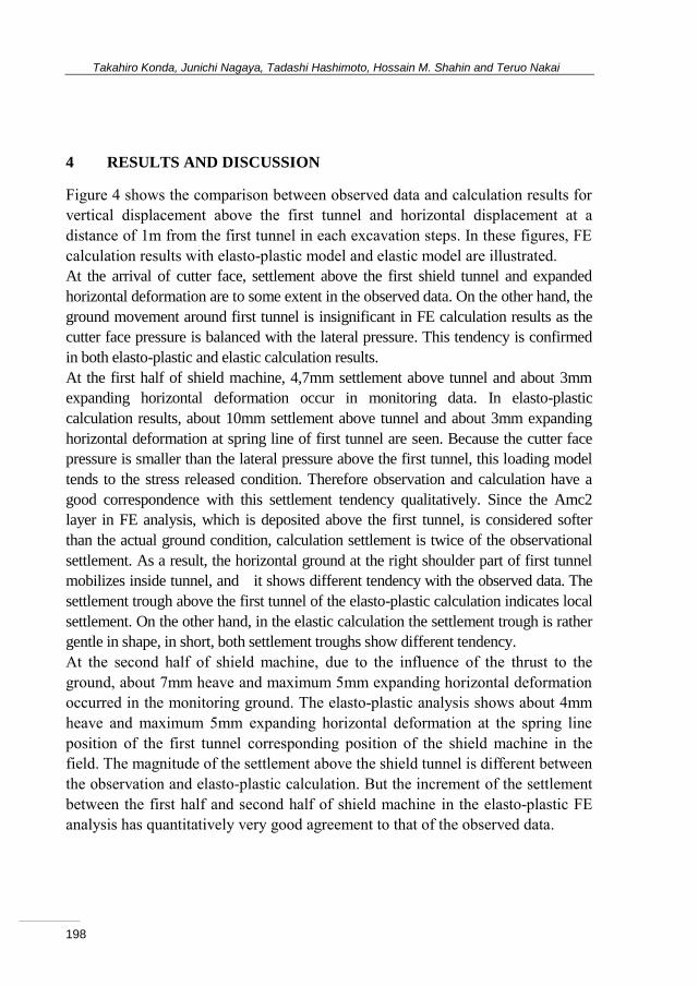
4 RESULTS AND DISCUSSION
Figure 4 shows the comparison between observed data and calculation results for
vertical displacement above the first tunnel and horizontal displacement at a
distance of 1m from the first tunnel in each excavation steps. In these figures, FE
calculation results with elasto-plastic model and elastic model are illustrated.
At the arrival of cutter face, settlement above the first shield tunnel and expanded
horizontal deformation are to some extent in the observed data. On the other hand, the
ground movement around first tunnel is insignificant in FE calculation results as the
cutter face pressure is balanced with the lateral pressure. This tendency is confirmed
in both elasto-plastic and elastic calculation results.
At the first half of shield machine, 4,7mm settlement above tunnel and about 3mm
expanding horizontal deformation occur in monitoring data. In elasto-plastic
calculation results, about 10mm settlement above tunnel and about 3mm expanding
horizontal deformation at spring line of first tunnel are seen. Because the cutter face
pressure is smaller than the lateral pressure above the first tunnel, this loading model
tends to the stress released condition. Therefore observation and calculation have a
good correspondence with this settlement tendency qualitatively. Since the Amc2
layer in FE analysis, which is deposited above the first tunnel, is considered softer
than the actual ground condition, calculation settlement is twice of the observational
settlement. As a result, the horizontal ground at the right shoulder part of first tunnel
mobilizes inside tunnel, and it shows different tendency with the observed data. The
settlement trough above the first tunnel of the elasto-plastic calculation indicates local
settlement. On the other hand, in the elastic calculation the settlement trough is rather
gentle in shape, in short, both settlement troughs show different tendency.
At the second half of shield machine, due to the influence of the thrust to the
ground, about 7mm heave and maximum 5mm expanding horizontal deformation
occurred in the monitoring ground. The elasto-plastic analysis shows about 4mm
heave and maximum 5mm expanding horizontal deformation at the spring line
position of the first tunnel corresponding position of the shield machine in the
field. The magnitude of the settlement above the shield tunnel is different between
the observation and elasto-plastic calculation. But the increment of the settlement
between the first half and second half of shield machine in the elasto-plastic FE
analysis has quantitatively very good agreement to that of the observed data.

In situ Measurement and Numerical Analysis on Tunnel Lining and Ground Behaviour due to Shield Excavation
199
Dep=
50.23m
O.P.
+4.67m
-20
-25
-10
-15
-5
O.P.+5.0m
0
0 10
No.1
5
503020 40 60
1112
下水φ3150
▽O.P.-11.872m
▽O.P.-17.307m
▽O.P.+4.67m
計測器
:層別沈下計
:連通管式沈下計
:多段式傾斜計
:間隙水圧計
:パッド式土圧計
500
2147
1000
1000
2000
15500
12150
1000
2000
15500
25000
31000
3つの計測器設置位置は南行
シールド側部から1.0m離れ
3720
Aus
Amc(1)
Amg
Amc(2)
Ams
Oc2
Tg
Os2
B
シールド 先行(南行)
後行(北行) シールド
沖積砂層(As)
沖積粘土層
(Ac)
沖積砂礫層
(Ag)
沖積粘土層
(Ac)
沖積砂層(As)
洪積粘土層(Oc)
洪積砂礫層(Tg)
:ひずみ計
Dep=
50.23m
O.P.
+4.67m
-20
-25
-10
-15
-5
O.P.+5.0m
0
0 10
No.1
5
503020 40 60
1112
下水φ3150
▽O.P.-11.872m
▽O.P.-17.307m
▽O.P.+4.67m
計測器
:層別沈下計
:連通管式沈下計
:多段式傾斜計
:間隙水圧計
:パッド式土圧計
500
2147
1000
1000
2000
15500
1215
010
0020
0015500
25000
3100
0
3つの計測器設置位置は南行
シールド側部から1.0m離れ
3720
Aus
Amc(1)
Amg
Amc(2)
Ams
Oc2
Tg
Os2
B
シールド 先行(南行)
後行(北行) シールド
沖積砂層(As)
沖積粘土層
(Ac)
沖積砂礫層
(Ag)
沖積粘土層
(Ac)
沖積砂層(As)
洪積粘土層(Oc)
洪積砂礫層(Tg)
:ひずみ計
-15 -10 -5 0 5 10 15-35
-30
-25
-20
-15
-10
-5
0
5
5mm
5mm horizontal deformation (obserbation)
vertical deformation (observation)
calculation (elasto-plastic model) calculation (elastic model)
1st
2nd
-15 -10 -5 0 5 10 15-35
-30
-25
-20
-15
-10
-5
0
5
5mm
5mm
1st
2nd
horizontal deformation (obserbation)
vertical deformation (observation)
calculation (elasto-plastic model) calculation (elastic model)
-15 -10 -5 0 5 10 15-35
-30
-25
-20
-15
-10
-5
0
5
5mm
5mm
1st
2nd
horizontal deformation (obserbation)
vertical deformation (observation)
calculation (elasto-plastic model) calculation (elastic model)
-15 -10 -5 0 5 10 15-35
-30
-25
-20
-15
-10
-5
0
5
5mm
5mm
1st
2nd
horizontal deformation (obserbation)
vertical deformation (observation)
calculation (elasto-plastic model) calculation (elastic model)
Figure 4: Comparison of vertical and horizontal ground deformation between observed data and
calculation results for each calculation step
Takahiro Konda, Junichi Nagaya, Tadashi Hashimoto, Hossain M. Shahin and Teruo Nakai
200
This same tendency is also captured in the distribution of lateral displacement at 1m
distance from the tunnel. On the other hand, the elastic calculation results can explain
the tendency of the heave above the tunnel and the expanding phenomenon for
considering the thrust model based on the shield machine position. However, for
instance, the influence of heave extends to the far ground surface, the elastic
calculation results are obviously different in comparison to the monitoring results and
the elasto-plastic calculation results. Moreover, the heave above the tunnel
significantly larger compare to the expanding horizontal deformation, this tendency
differs vastly from the observation and the elasto-plastic calculation.
The deformation behaviour at the tail passing is similar to its behaviour at the second
half of shield machine. Nevertheless, as the backfill grouting pressure balances with
the lateral pressure, the local heave is restricted appropriately and elasto-plastic
calculation results have a good correspond with monitoring data in comparison with
elastic calculation results.
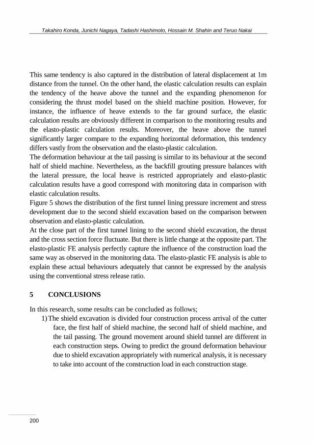
Figure 5 shows the distribution of the first tunnel lining pressure increment and stress
development due to the second shield excavation based on the comparison between
observation and elasto-plastic calculation.
At the close part of the first tunnel lining to the second shield excavation, the thrust
and the cross section force fluctuate. But there is little change at the opposite part. The
elasto-plastic FE analysis perfectly capture the influence of the construction load the
same way as observed in the monitoring data. The elasto-plastic FE analysis is able to
explain these actual behaviours adequately that cannot be expressed by the analysis
using the conventional stress release ratio.
5 CONCLUSIONS
In this research, some results can be concluded as follows;
1) The shield excavation is divided four construction process arrival of the cutter
face, the first half of shield machine, the second half of shield machine, and
the tail passing. The ground movement around shield tunnel are different in
each construction steps. Owing to predict the ground deformation behaviour
due to shield excavation appropriately with numerical analysis, it is necessary
to take into account of the construction load in each construction stage.

In situ Measurement and Numerical Analysis on Tunnel Lining and Ground Behaviour due to Shield Excavation
201
-50
0
100
Lining Pressure
50
Unit : kN/m2
second half of shield machine (observation) tail passing (observation) second half of shield machine (calculation) tail passing (calculation)
50
-50
-100
Bending Moment
0
Unit : kNm
+ : in tension, out compression- : in compression, out tension
Figure 5: Comparison of distribution of earth pressure increment and cross section force of 1st
tunnel lining between observed data and calculation results for each calculation step
2) It can be thought that some factors for ground deformation are - i) the balance
between the cutter face pressure and the lateral pressure at the cutter face, ii) the
balance between the cutter face pressure and the lateral pressure at the first half of
shield machine, iii) the differential pressure between the backfill grouting pressure
and the ground pressure around tunnel at the second half of shield machine and at
the tail passing, and iv) the self-weight of shield machine. Sometime, the thrust
associated with the difference between the excavation direction and shield
machine positions has an impact to ground deformation.
3) The FE analysis with elasto-plastic constitutive model of soil and the load model
considering construction loads is employed to simulate the ground deformation
behaviour around tunnel and the nearby tunnel lining pressure and stress
development. It is revealed that the elasto-plastic FE analysis is able to explain
actual behaviours adequately that cannot be expressed by the analysis using the
conventional stress release ratio. Moreover, the elasto-plastic calculation results
have a good agreement with the monitoring data in comparison with the elastic
calculation results.

Takahiro Konda, Junichi Nagaya, Tadashi Hashimoto, Hossain M. Shahin and Teruo Nakai
202
REFERENCES
[1] Konda T., Shahin, H. M. and Nakai, T.: Numerical Analysis for backside
ground deformation behaviour due to braced excavation, 9th World
Congress on Computational Mechanics and 4th Asia Pacific Congress on
Computational Mechanics, P Antolin et al IOP Conf. Ser.: Mater. Sci. Eng.
Vol.10, No.1, 2010.
[2] Nakai, T., Hinokio, M. 2004. A Simple Elastoplastic Model for normally and
over consolidated soil with unified material parameters. Soils and
Foundations, 44(2), pp. 53-70.
[3] Shahin, H. M., Nakai, T, Zhang, F., Kikumoto, M. and Nakahara E.,
“Behavior of ground and response of existing foundation due to tunneling”,
Soils and Foundations, Vol. 51, No. 3, 2011, pp. 395-409.
[4] Oota H., A. Hashimoto, J. Nagaya and S. Kan: Measurement and
consideration of ground deformation due to shield tunnel construction loads,
The Proc. Of Tunnel engineering JSCE, vol.16, pp.395-402, 2006.