in-situ measurements of thermo-mechanical characteristics ... · dsc, tma, dtma. thermo-mechanical...
TRANSCRIPT

In-situ Measurements of Thermo-Mechanical Characteristics of PEMs’ Molding Compounds
Alexander TeverovskyQSS Group, Inc.\Goddard Operations

M&A COTS Aug.'03 2
Background
Transition from a glassy to rubbery state drastically changes thermal, mechanical, electrical, and diffusion characteristics of epoxy molding compounds.
Transition from a glassy to rubbery state drastically changes thermal, mechanical, electrical, and diffusion characteristics of epoxy molding compounds.
Diffusion Elastic Modulus
Electrical conductivity
Heat capacity
TA Instruments
Darveaux et al.’ 95
P.Chen et al.’ 2000
Vieth ‘91

M&A COTS Aug.'03 3
Background. Cont’d.Several techniques can be used for Tg measurements: DSC, TMA, DTMA. Thermo-mechanical analysis (TMA) is most suitable for PEMs. It also allows to obtain CTE.TMA might be useful to ensure consistent quality of MC and check for proper curing.Tg and CTE might affect the performance and reliability of PEMs at extreme temperatures and change the rate of failures.High temperature stress testing is commonly used to screen and qualify COTS PEMs for high reliability applications. Exceeding Tg might introduce new failure mechanisms. (Analysis of the significance of Tg for screening and qualification will be discussed in a separate paper.)

M&A COTS Aug.'03 4
Purpose
To analyze possible errors of in-situ thermo-mechanical analysis (TMA) of PEMs.To develop a procedure for assessment of Tg and CTE of MCs directly on PEMs.To illustrate the effectiveness of TMA for qualification of PEMs.To demonstrate the value of TMA for failure analysis.

M&A COTS Aug.'03 5
OutlineFactors affecting Tg and CTE measurements on PEMs:
Temperature rate;Lead frame;Warpage;Moisture content;
Standardized procedure for TMA on PEMs.TMA application for lot qualification:
Effect of curing conditions;Lot-to-lot variation.
History cases of PEM failures:Delaminations after BI;Delaminations after HAST;Wire bond failures in parts with silicone die coating.

M&A COTS Aug.'03 6
TMA of PEMs is very simple …
TMA2940PEM
Quartz probe
Thermocouple

M&A COTS Aug.'03 7
…understanding the results might be more challenging.
Major problems with TMA measurements on PEMs:Warpage;Stress relief;Moisture;Lead frame;Temperature rate;Cooling vs. heating
Major problems with TMA measurements on PEMs:Warpage;Stress relief;Moisture;Lead frame;Temperature rate;Cooling vs. heating

M&A COTS Aug.'03 8
Existing TMA standardsStandard Materials Preconditi
oningRate,
oC/minComments
ASTM E 831 All solid materials
Not specified
5 Heating rate might be adjusted depending on thermal characteristics of materials
IPC-TM-650, N 2.4.41.1
Laminated materials
Isopropyl alcohol
2 Two thermal cycles per test is recommended. 1st to normalize the specimens, 2nd to measure
IPC-TM-650, N 2.4.24
Printed boards 2 hr 105 oC 10 If residual stress cause irreversible deflection at glass transition, a second scan shall be run
IPC-TM-650, N 2.4.24.3
Organic films24 hr, 50% RH, 23 oC
5 Prescan: 20 oC/min up 50 oC above Tg, hold 10 min, cool to 50 oC below Tg, hold 10 min.
IPC-TM-650, N 2.4.24.5
Dielectr. HD interconnection 1 hr 105 oC 5
If unexpected shrinkage observed the two-heat test method is required. 1st cycle at 10 oC/min
There is no standard for TMA on PEMs.Existing standards have:• different heating rates,• insufficient baking for PEMs,• warning about stress relief problems.
There is no standard for TMA on PEMs.Existing standards have:• different heating rates,• insufficient baking for PEMs,• warning about stress relief problems.
M&A COTS Aug.'03 9
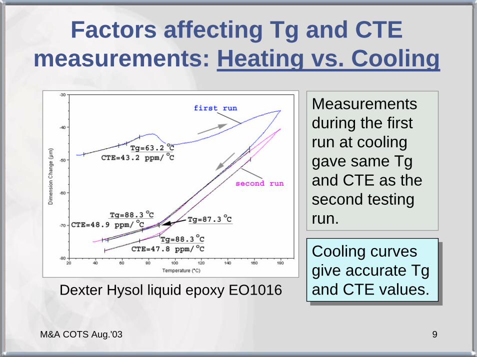
Factors affecting Tg and CTE measurements: Heating vs. Cooling
Measurements during the first run at cooling gave same Tg and CTE as the second testing run.
Cooling curves give accurate Tg and CTE values.
Cooling curves give accurate Tg and CTE values.Dexter Hysol liquid epoxy EO1016

M&A COTS Aug.'03 10
Factors affecting Tg and CTE measurements: temperature rate
Calculated maximum temperature rate vs. package thicknessCharacteristic time of
temperature distribution:τ ≈ ρ×C×H2/λ
H – thickness; λ - specific thermal conductivity, C - heat capacity; ρ -specific density.
To ensure that T variations < ∆T:
the maximum temperature rate:
τα
≥∆T
2max HCT
×××∆=
ρλα Most PEMs can be tested
at a rate of 3 oC/minMost PEMs can be tested
at a rate of 3 oC/min

M&A COTS Aug.'03 11
Factors affecting Tg and CTE measurements: lead frame
When deformation of MC and LF are independent:
At HLF<<HMC and/or αpac ≈ αLF
αMC ≈ αpac
LF constrains are similar to glass fiber effect in PWB and might change CTE in Z-axis.
In some cases LF might affect deformation of MC
)( LFpacMC
LFpacMC H
H αααα −×+=

M&A COTS Aug.'03 12
Factors affecting Tg and CTE measurements: lead frame. Cont’d.
Average Tg and CTE measured on MC and packagesTg MC Tg pack CTE1 MC CTE1 pack CTE2 MC CTE2 pack
PEM1 149.8 143.3 22.5 24 75.5 79.5PEM2 162.9 165.1 21.4 23.7 61 71.5PEM3 171.4 165.8 21.8 26.6 62 72.4PEM4 166 159.1 21 23.2 69.7 65.6PEM5 155.5 153.3 16.2 18.4 74.7 92.2
• CTE of MC is 6% to 22% lower than for packages.• Tg of MCs are 2 to 7 oC higher than for packages.
[Hongsmatip T. ’97]: packages had ~5% lower Tg than molded test specimens.
• CTE of MC is 6% to 22% lower than for packages.• Tg of MCs are 2 to 7 oC higher than for packages.
[Hongsmatip T. ’97]: packages had ~5% lower Tg than molded test specimens.
M&A COTS Aug.'03 13
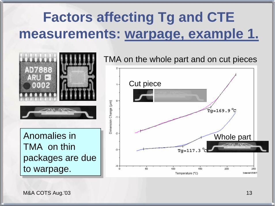
Factors affecting Tg and CTE measurements: warpage, example 1.
TMA on the whole part and on cut pieces
Whole part
Cut piece
Anomalies in TMA on thin packages are due to warpage.
Anomalies in TMA on thin packages are due to warpage.

M&A COTS Aug.'03 14
Factors affecting Tg and CTE measurements: warpage, example 2.
At H = 0.95 mm, the characteristic time for moisture outdiffusionat 125 oC is ~ 3 hrs.
Deformation of a thin TSOP32 package during isothermal baking Initial measurements
resulted in erroneous Tg of 99.5 oC. After stress relief Tg = 132 oC.

M&A COTS Aug.'03 15
Factors affecting Tg and CTE measurements: warpage, example 3.
Package TSSOP24, size: 7.8×4.5 ×0.9 mm3
Measurements on package,
Tg = 99 oC
Measurements on a cut piece,Tg = 169 oC
Warpage of PEMswith high aspect ratio might result in anomaly low Tg.
Warpage of PEMswith high aspect ratio might result in anomaly low Tg.
M&A COTS Aug.'03 16
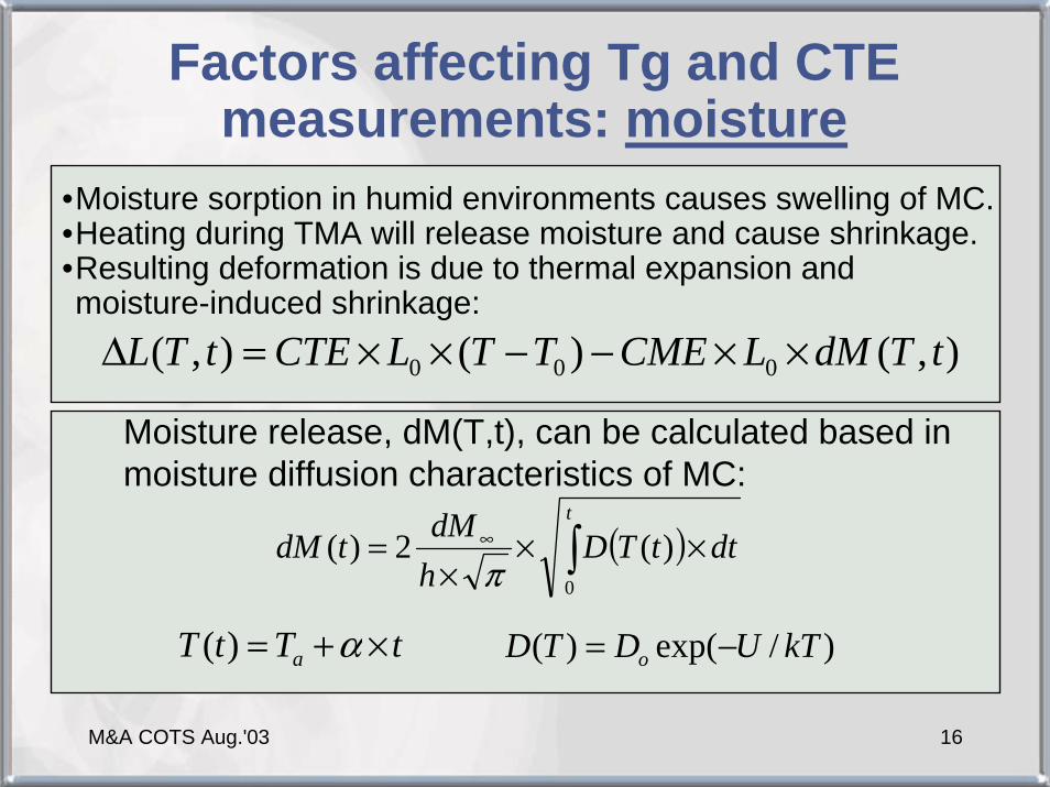
Factors affecting Tg and CTE measurements: moisture
•Moisture sorption in humid environments causes swelling of MC. •Heating during TMA will release moisture and cause shrinkage. •Resulting deformation is due to thermal expansion and moisture-induced shrinkage:
),()(),( 000 tTdMLCMETTLCTEtTL ××−−××=∆
Moisture release, dM(T,t), can be calculated based in moisture diffusion characteristics of MC:
( )∫ ×××
= ∞t
dttTDhdMtdM
0
)(2)(π
)/exp()( kTUDTD o −=tTtT a ×+= α)(

M&A COTS Aug.'03 17
Factors affecting Tg and CTE measurements: moisture. Cont’d.
Results of calculations.Do=7.3×10⁻² cm2/s, U=0.43 eV, α=1
oC/min, CTE1/2=17/50 ppm/oC, Tg=150 oC, dM∞=0.5%, CME=0.5
Effect of moisture on TMA measurements
-2.00
0.00
2.00
4.00
6.00
8.00
10.00
40 60 80 100 120 140 160 180 200 220
temperature, deg.C
dL, u
m
wetdry
CTE1=13.5
CTE1=17 ppm/C
CTE2=50 ppm/C
CTE2=39
Experimental TMA results.PN IRLL110 after HAST.
Hysteresis is due to moisture desorption.
Moisture release results in shrinkage and reduces CTE.Moisture release results in shrinkage and reduces CTE.

M&A COTS Aug.'03 18
Factors affecting Tg and CTE measurements: moisture. Cont’d.
Effect of HAST on Tg, oCPackage Tg HAST Tg bake
PEM1 DIP28 135 135PEM2 TO220 144 144PEM3 TO220 157 157PEM4 QFP144 156 156PEM5 DIP8 158 158PEM6 TO220 157 157PEM7 SOT223 155 155PEM8 SOIC8 169 175PEM9 SOIC8 152 182
PEM10 SOIC8 170 181PEM11 SOIC8 120 137
The presence of moisture plasticizesepoxy matrix in molding compounds and reduces Tg from 10 oCto 30 oC.
The presence of moisture plasticizesepoxy matrix in molding compounds and reduces Tg from 10 oCto 30 oC.

M&A COTS Aug.'03 19
Standardized procedure for Tg and CTE measurements
Two purposes of PEMs’ TMA:Assessment of Tg and CTE of molding compound;Analysis of anomalies in package deformation (FA);
Procedure for Tg and CTE assessment:Bake the part at 150 oC for 1.9×H2 hours, where H is the thickness of the package in mm.Record the data at 3 oC/min during heating up from RT to 220 oC and cooling to 50 oC at the same rate.Calculate Tg, CTE1 and CTE2 using cooling curve. If moisture and stress relief are not sufficient repeat the test.Note: warpage of PEMs results in erroneous measurements especially for parts with high aspect ratio (H ~ 0.8 to 1.5 mm and L of > 3 mm). For these parts the measurement shall be performed on small pieces cut from the package.

M&A COTS Aug.'03 20
Lot qualification: effect of curing conditions
Post-mold cure does not affect CTE and increases Tg from ~20 to 30 oCPost-mold cure does not affect CTE and increases Tg from ~20 to 30 oC
• Density decreases ~0.47%. • Post-mold curing does not
improve diffusion characteristics of MCs.
Encapsulant dM/M, % dV/V, % dρ /ρ , %MC1 0.114 0.357 0.47MC2 0.106 0.364 0.47
Effect of post-mold curing on M, V, and density of two MCs
Effect of post-mold curing on Tg and CTE
The higher Tg the more porous MC is?The higher Tg the
more porous MC is?
M&A COTS Aug.'03 21
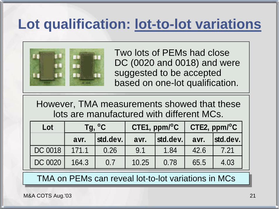
Lot qualification: lot-to-lot variations
Two lots of PEMs had close DC (0020 and 0018) and were suggested to be accepted based on one-lot qualification.
Lotavr. std.dev. avr. std.dev. avr. std.dev.
DC 0018 171.1 0.26 9.1 1.84 42.6 7.21DC 0020 164.3 0.7 10.25 0.78 65.5 4.03
Tg, oC CTE1, ppm/oC CTE2, ppm/oC
However, TMA measurements showed that these lots are manufactured with different MCs.
TMA on PEMs can reveal lot-to-lot variations in MCsTMA on PEMs can reveal lot-to-lot variations in MCs

M&A COTS Aug.'03 22
Lot qualification: MC for different package types
There is an assumption that better quality MC have higher Tg.Do newer design packages have higher Tg?
TM characteristics of MC for the same part in different packagesPart Package Tg, oC CTE1, ppm/oC CTE2, ppm/oC
PEM1 DIP8 156 16.4 102uSOIC8 169 14.7 76
PEM2 DIP8 158 20.8 83.4uSOIC8 142 10.3 42.2
Low Tg MC are not inferior compared to high Tg.Newer design of PEMs might employ MCs with lower Tg.
Low Tg MC are not inferior compared to high Tg.Newer design of PEMs might employ MCs with lower Tg.

M&A COTS Aug.'03 23
FA history case 1: BI-induced delaminations
Initial after BI
Delaminations were observed at critical wire bond areas in all tested after BI parts. Is there a reliability problem?This result was difficult to predict considering relatively low temperature of the stress.Note: no delaminations on the corner leads.
Typical acoustic images showing finger-tip delaminations after
burn-in testing at 85 oC
M&A COTS Aug.'03 24
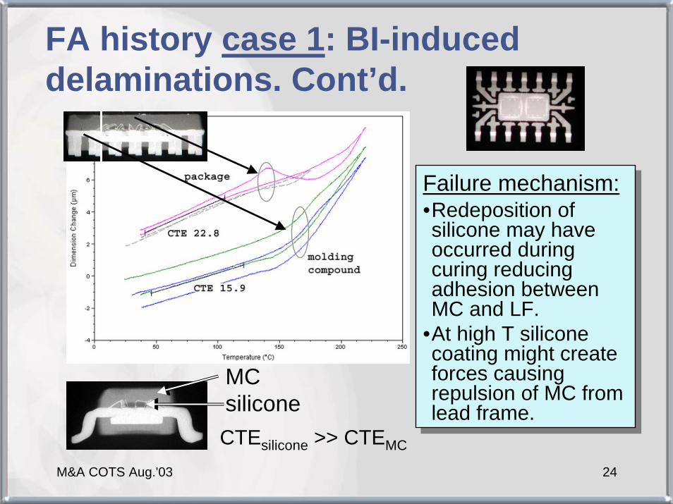
FA history case 1: BI-induced delaminations. Cont’d.
CTEsilicone >> CTEMC
MCsilicone
Failure mechanism:•Redeposition of silicone may have occurred during curing reducing adhesion between MC and LF.
•At high T silicone coating might create forces causing repulsion of MC from lead frame.
Failure mechanism:•Redeposition of silicone may have occurred during curing reducing adhesion between MC and LF.
•At high T silicone coating might create forces causing repulsion of MC from lead frame.

M&A COTS Aug.'03 25
FA History case 2: HAST-induced delaminationsBackground: Multiple CSAM failures of PEMs in SOT-23-5 packages were observed after HAST. No electrical failures occurred.
FA purpose: Why, and is there a reliability concern?
Acoustic images after HASTTop side view Bottom side view
M&A COTS Aug.'03 26
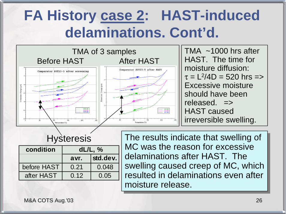
FA History case 2: HAST-induced delaminations. Cont’d.
Hysteresis
TMA of 3 samplesBefore HAST After HAST
conditionavr. std.dev.
before HAST 0.21 0.048after HAST 0.12 0.05
dL/L, %The results indicate that swelling of MC was the reason for excessivedelaminations after HAST. The swelling caused creep of MC, which resulted in delaminations even after moisture release.
The results indicate that swelling of MC was the reason for excessivedelaminations after HAST. The swelling caused creep of MC, which resulted in delaminations even after moisture release.
TMA ~1000 hrs after HAST. The time for moisture diffusion:τ = L2/4D = 520 hrs => Excessive moisture should have been released. => HAST caused irreversible swelling.
M&A COTS Aug.'03 27
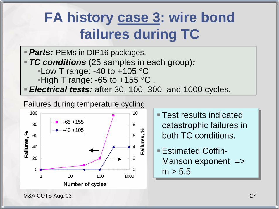
FA history case 3: wire bond failures during TC
Parts: PEMs in DIP16 packages.TC conditions (25 samples in each group):
•Low T range: -40 to +105 °C•High T range: -65 to +155 °C .
Electrical tests: after 30, 100, 300, and 1000 cycles.
Test results indicated catastrophic failures in both TC conditions.
Estimated Coffin-Manson exponent => m > 5.5
Test results indicated catastrophic failures in both TC conditions.
Estimated Coffin-Manson exponent => m > 5.5 0
20
40
60
80
100
1 10 100 1000
Number of cycles
Failu
res,
%
0
2
4
6
8
10
Failu
res,
%
-65 +155-40 +105
Failures during temperature cycling
M&A COTS Aug.'03 28
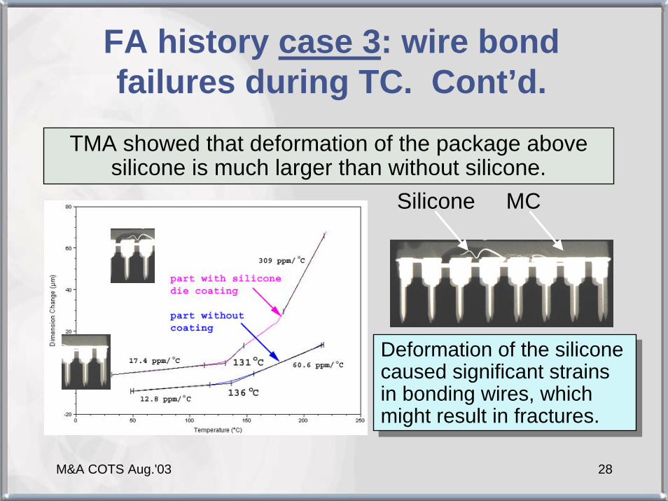
FA history case 3: wire bond failures during TC. Cont’d.
TMA showed that deformation of the package above silicone is much larger than without silicone.
Silicone MC
Deformation of the silicone caused significant strains in bonding wires, which might result in fractures.
Deformation of the silicone caused significant strains in bonding wires, which might result in fractures.

M&A COTS Aug.'03 29
FA history case 3: wire bond failures during TC. Cont’d.
Normal part
Failed part
Broken wires
Silicone die coating
X-ray and cross-sectioning confirmed wire bond fractures
X-ray and cross-sectioning confirmed wire bond fractures Broken
wire
Pictures courtesy of F.Felt
M&A COTS Aug.'03 30
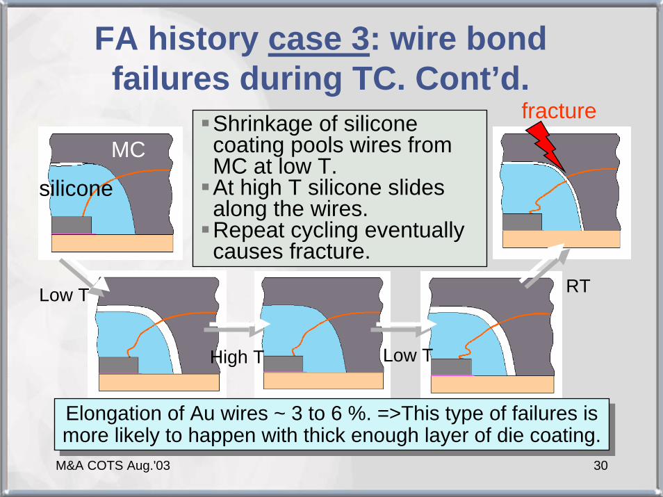
FA history case 3: wire bond failures during TC. Cont’d.
Shrinkage of silicone coating pools wires from MC at low T.At high T silicone slides along the wires.Repeat cycling eventually causes fracture.
Low T
High T Low T
RT
fracture
Elongation of Au wires ~ 3 to 6 %. =>This type of failures is more likely to happen with thick enough layer of die coating.Elongation of Au wires ~ 3 to 6 %. =>This type of failures is more likely to happen with thick enough layer of die coating.
MC
silicone
M&A COTS Aug.'03 31
Conclusions
Tg and CTE of MC can be accurately assessed by TMA measurements of PEMs provided care is taken regarding possible warpage, stress relief, and moisture content.A standardized procedure for in-situ TMA of PEMs is suggested.TMA of plastic packages is a useful tool for lot qualification of molding compounds and for analysis of PEMs’ failures.