in situ thermal remediation81466bf2-f6f6-41c9...2016/09/30 · the materials and information herein...
TRANSCRIPT

IN SITU THERMAL REMEDIATION
Mark Klemmer
September 30, 2016
© Arcadis 2016
Disclaimers and NoticesThe materials herein are intended to furnish viewers with a summary and overview of general information on matters that they may find to be of interest, and are provided solely for personal, non-commercial, and informational purposes. The materials and information contained herein are subject to continuous change and may not be current, correct, or error free, and should not be construed as professional advice or service. You should consult with an Arcadis or other professional familiar with your particular factual situation for advice concerning specific matters.
THE MATERIALS AND INFORMATION HEREIN ARE PROVIDED "AS IS" AND “WITH ALL FAULTS” AND WITHOUT ANY REPRESENTATION OR WARRANTY, EXPRESS, IMPLIED OR STATUTORY, OF ANY KIND BY ARCADIS, INCLUDING, BUT NOT LIMITED TO, WARRANTIES OF MERCHANTABILITY, NON-INFRINGEMENT, NO ERRORS OR OMISSIONS, COMPLETENESS, ACCURACY, TIMELINESS, OR FITNESS FOR ANY PARTICULAR PURPOSE. ARCADIS DISCLAIMS ALL EQUITABLE INDEMNITIES. ANY RELIANCE ON THE MATERIALS AND INFORMATION HEREIN SHALL BE AT YOUR SOLE RISK. ARCADIS DISCLAIMS ANY DUTY TO UPDATE THE MATERIALS. ARCADIS MAY MAKE ANY OTHER CHANGES TO THE MATERIALS AT ANY TIME WITHOUT NOTICE.
The materials are protected under copyright laws and may not be copied, reproduced, transmitted, displayed, performed, distributed, rented, sublicensed, altered, or otherwise used in whole or in part without Arcadis' prior written consent.

© Arcadis 2016
About the Presenter
27 September 2016 3
o 248 994 2260c 248 867 1805e [email protected]
MARK KLEMMER, PEVice President | Technical Expert
© Arcadis 2016
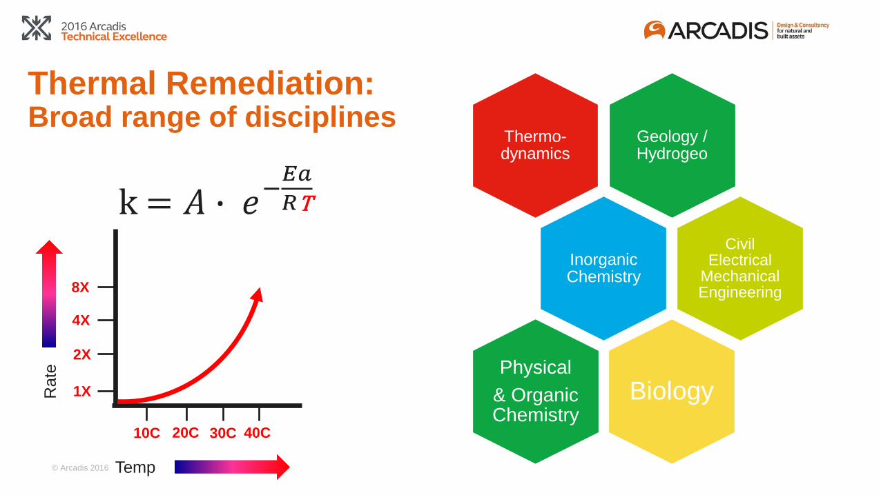
Thermal Remediation: Broad range of disciplines
Geology / Hydrogeo
Biology
Inorganic Chemistry
Civil Electrical
Mechanical Engineering
Thermo-dynamics
Physical& Organic Chemistry
Temp
Rat
e
10C 20C 30C 40C
1X
2X
4X
8X
k = 𝐴𝐴 � 𝑒𝑒−𝐸𝐸𝐸𝐸𝑅𝑅𝑇𝑇T
© Arcadis 2016
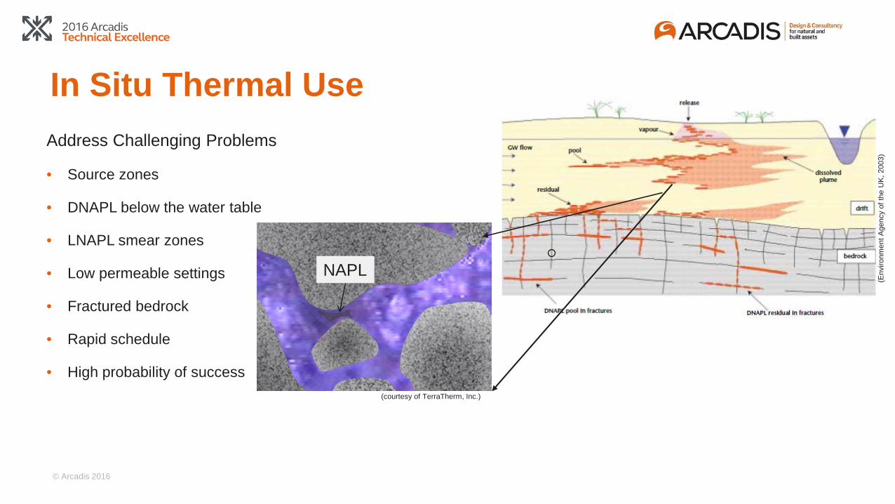
In Situ Thermal UseAddress Challenging Problems
• Source zones
• DNAPL below the water table
• LNAPL smear zones
• Low permeable settings
• Fractured bedrock
• Rapid schedule
• High probability of success
NAPL
(Env
ironm
ent A
genc
y of
the
UK,
200
3)
(courtesy of TerraTherm, Inc.)

© Arcadis 2016
Thermal Removal Mechanisms
• Volatilization of NAPL: Vapor pressure / boiling point
• Stripping of dissolved phase: Henry’s Law
(cou
rtesy
of T
erra
Ther
m)

© Arcadis 2016
Thermal Removal Mechanisms
0
100
200
300
400
500
600
700
0 100 200 300 400 500
Vapor Pressures Increase Exponentially During Heating
100°C >100°C
Vapo
r Pre
ssur
e (m
m H
g)
Temperature (°C)
Target Temperature:
(afte
r Ter
raTh
erm
)

© Arcadis 2016
0
100
200
300
400
500
600
700
800
0 10 20 30 40 50 60 70 80 90 100 110 120 130
Total Pressure
Vapor Pressure PCE
Vapor Pressure ofWater
Thermal Removal Mechanisms
• Formation of Low Boiling Point Azeotropes
• Co-boiling at water-NAPL interface; example: PCE and Water
Vapo
r Pre
ssur
e m
m H
g
Temperature °C
1 ATM
88°C
121°C
(Ste
amTe
ch)
88°C

© Arcadis 2016
Boiling of Azeotropic Mixture
Vapor pressure at water-NAPL interface is
additive

© Arcadis 2016
Conceptual Model of Typical ISTR Site
Power distribution system
Vapor treatment
Knockout pot
Blower
Water treatmentDischargeVapor cap
Electrodes/Heater wells/Steam Injection wells
Treated vapor to atmosphere
Extraction well
Heat exchanger
Pump
Treatment area foot-print
Temperature and pressure monitoring holes
(afte
r Ter
raTh
erm
)

© Arcadis 2016
Thermal Conductive Heating (TCH) – Gas-Fired Well Field Contaminant Vapors and
SteamGas Burner
Re-HeaterWell
Exhaust
GW Flux < 1 ft/day
(afte
r Ter
raTh
erm
)
© Arcadis 2016
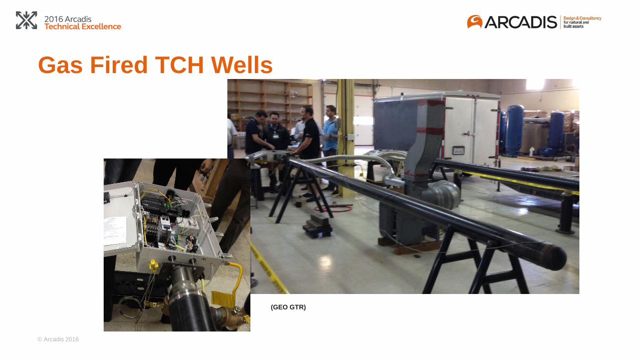
Gas Fired TCH Wells
(GEO GTR)
ISTDHeater Well
© Arcadis 2016
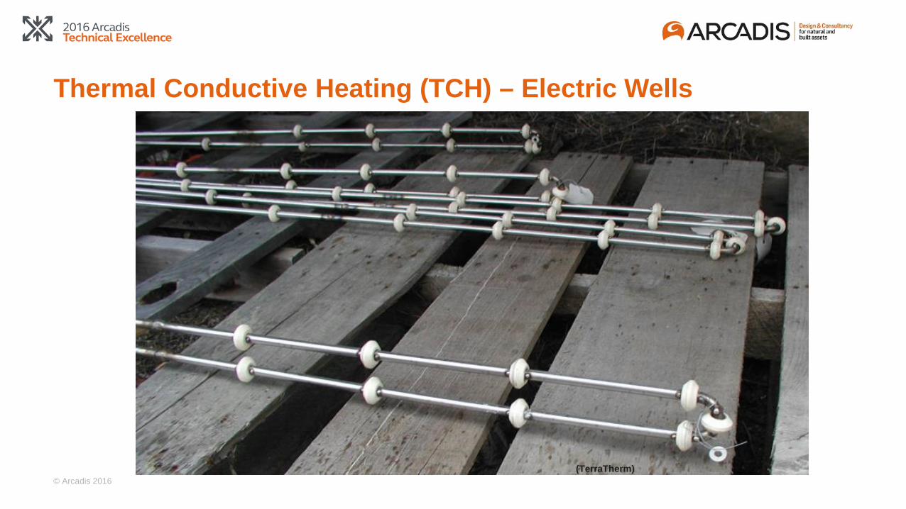
Thermal Conductive Heating (TCH) – Electric Wells
(TerraTherm)

© Arcadis 2016
Electric TCH Well Field
(TerraTherm)

© Arcadis 2016
Electrical Resistance Heating
Sand
Contaminant Vapors, Steam, and Liquids
Water Water
Rate and Uniformity of
Heating Governed by Soil Resistivity
Varies by a Factor of ~200
GW Flux < 1 ft/day
(afte
r Ter
raTh
erm
)
Electrode
© Arcadis 2016
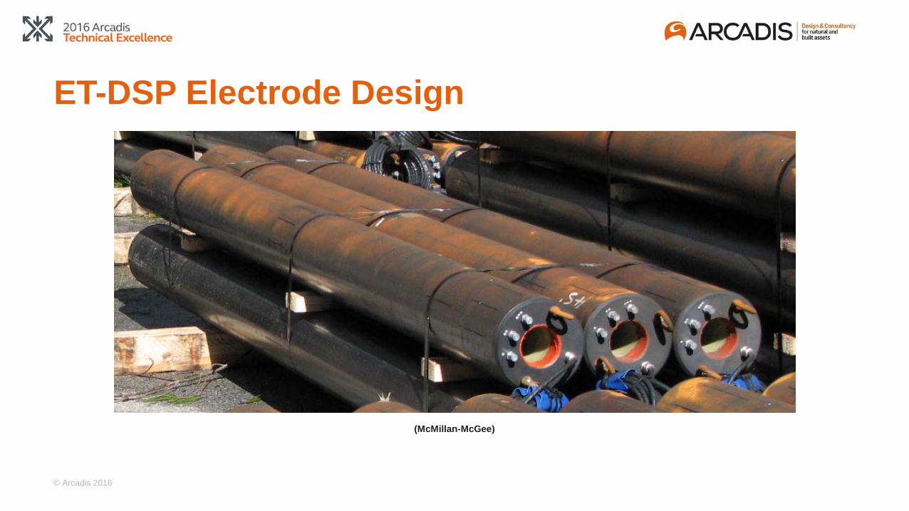
ET-DSP Electrode Design
(McMillan-McGee)

© Arcadis 2016
ERH Well Field
MPEWells
StackedElectrodes
Power Distribution SystemFor Electrodes
Vapor and Liquid Manifolds
Water Distribution SystemFor Electrodes

© Arcadis 2016
Sometimes One Technology Alone Won’t Get the Job Done Contaminant Vapors and Steam
GW GW Flux > 1 ft/day
(afte
r Ter
raTh
erm
)
© Arcadis 2016
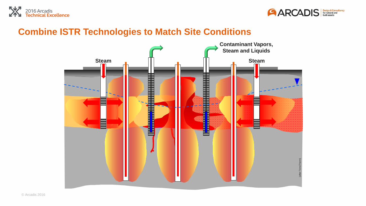
Combine ISTR Technologies to Match Site ConditionsContaminant Vapors,
Steam and Liquids
Steam Steam
(afte
r Ter
raTh
erm
)
© Arcadis 2016
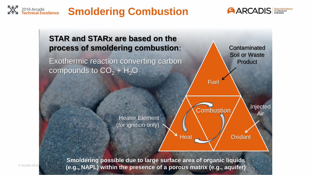
Smoldering Combustion
STAR and STARx are based on the process of smoldering combustion:Exothermic reaction converting carbon compounds to CO2 + H2O
Fuel
Heat Oxidant
Smoldering possible due to large surface area of organic liquids (e.g., NAPL) within the presence of a porous matrix (e.g., aquifer)
Combustion
Contaminated Soil or Waste
Product
Injected Air
Heater Element (for ignition only)
© Arcadis 2016
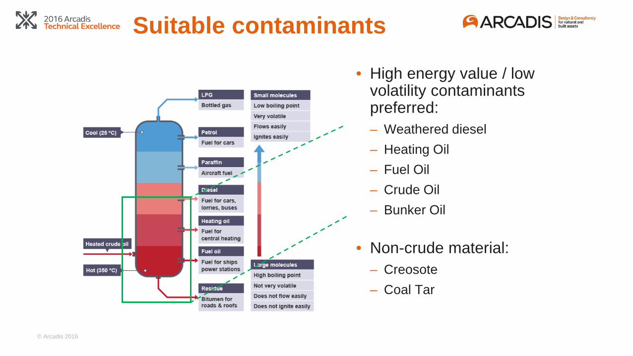
Suitable contaminants
• High energy value / low volatility contaminants preferred:– Weathered diesel– Heating Oil– Fuel Oil– Crude Oil– Bunker Oil
• Non-crude material:– Creosote– Coal Tar

© Arcadis 2016
Low Temperature Thermal – Enhanced Hydrolysis Reactions
(Klemmer, et al, 2012)
0
1
100
10,000
1,000,000
100,000,000
10,000,000,000
1,000,000,000,000
100,000,000,000,000
10 30 50 70 90 110
Cal
cula
ted
Hal
f Life
(day
s)
Temperature (°C)
1,2-DCE
PCE
1,1-DCE
TCE
CF
1,1,2-TCA
1,2-DCA
1,1-DCA
CT
CA
1,1,2,2-TeCA
1,1,1-TCA
PeCA
1,2-DCP
Data Sources: Jeffers et al. (1989, 1996) and Washington (1995)
1,1-DCEAcetic Acid
Cl
Cl
Cl
1,1,1-TCA
H
H
H

© Arcadis 2016
0
10
20
30
40
50
60
0
5,000
10,000
15,000
20,000
25,000
30,000
35,000
40,000
45,000
50,000
-300 -264 -176 13 41 69 100 125 152 219 240
Tem
pera
ture
˚C
Con
cent
ratio
n (m
icro
gram
s pe
r lite
r)
Days Since Start
1,1-DCE1,1,1-TCATemperature
Source Area Well Performance
© Arcadis 2016
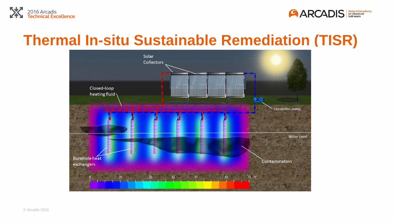
Thermal In-situ Sustainable Remediation (TISR)

© Arcadis 2016
Thermal Modeling
8 m
35 °C

© Arcadis 2016
Arcadis.Improving quality of life.
2727 September 2016