in step with ins - infoscience.epfl.ch step with ins.pdf · sage is output. the pnm updates infor-...
TRANSCRIPT
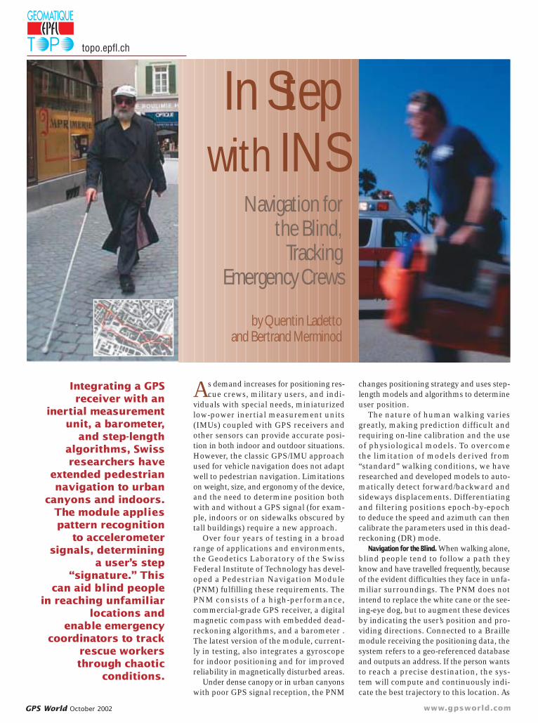
As demand increases for positioning res-cue crews, military users, and indi-
viduals with special needs, miniaturizedlow-power inertial measurement units(IMUs) coupled with GPS receivers andother sensors can provide accurate posi-tion in both indoor and outdoor situations.However, the classic GPS/IMU approachused for vehicle navigation does not adaptwell to pedestrian navigation. Limitationson weight, size, and ergonomy of the device,and the need to determine position bothwith and without a GPS signal (for exam-ple, indoors or on sidewalks obscured bytall buildings) require a new approach.
Over four years of testing in a broadrange of applications and environments,the Geodetics Laboratory of the SwissFederal Institute of Technology has devel-oped a Pedestrian Navigation Module (PNM) fulfilling these requirements. ThePNM consists of a high-performance, commercial-grade GPS receiver, a digitalmagnetic compass with embedded dead-reckoning algorithms, and a barometer .The latest version of the module, current-ly in testing, also integrates a gyroscopefor indoor positioning and for improvedreliability in magnetically disturbed areas.
Under dense canopy or in urban canyonswith poor GPS signal reception, the PNM
GPS World October 2002 www.gpsworld.com
changes positioning strategy and uses step-length models and algorithms to determineuser position.
The nature of human walking variesgreatly, making prediction difficult andrequiring on-line calibration and the useof physiological models. To overcomethe limitation of models derived from “standard” walking conditions, we haveresearched and developed models to auto-matically detect forward/backward andsideways displacements. Differentiatingand filtering positions epoch-by-epochto deduce the speed and azimuth can thencalibrate the parameters used in this dead-reckoning (DR) mode.
Navigation for the Blind. When walking alone,blind people tend to follow a path theyknow and have travelled frequently, becauseof the evident difficulties they face in unfa-miliar surroundings. The PNM does notintend to replace the white cane or the see-ing-eye dog, but to augment these devicesby indicating the user’s position and pro-viding directions. Connected to a Braillemodule receiving the positioning data, thesystem refers to a geo-referenced databaseand outputs an address. If the person wantsto reach a precise destination, the sys-tem will compute and continuously indi-cate the best trajectory to this location. As
Integrating a GPSreceiver with an
inertial measurementunit, a barometer,
and step-lengthalgorithms, Swissresearchers have
extended pedestriannavigation to urban
canyons and indoors.The module appliespattern recognition
to accelerometersignals, determining
a user’s step“signature.” This
can aid blind peoplein reaching unfamiliar
locations and enable emergency
coordinators to trackrescue workersthrough chaotic
conditions.
In Stepwith INS
Navigation for the Blind,
Tracking Emergency Crews
by Quentin Ladetto and Bertrand Merminod
topo.epfl.ch

the Braille–GPS software allows regis-tering waypoints, the system can map placesof interest such as bus stops, shops, andso on. Its principal advantage is not rely-ing purely on GPS visibility, so it can beextended for indoor applications and ismuch more reliable in downtown envi-ronments.
Positioning Rescuers. In an emergency, coor-dinating rescue groups or individuals in avery rapid timeframe is always crucial.Knowing each crew member’s position,both once an alarm sounds — beforeresponse has begun — and during the actu-al rescue work, can contribute greatly tosafety and lifesaving. This is particularlytrue when crew members have enteredbuildings.
Module ComponentsThe adjacent photos depict stages of PNMdevelopment, and Figure 1 presents the inte-grated data flow.
Accuracy. The current PNM prototypeuses the GPS receiver in navigation modeonly, with no differential correction, deliv-ering precision of absolute positions of�10 meters. The relative positions betweenepochs are used to calibrate different mod-els, and these have a much better rela-tive precision, less than 1 meter.
The digital magnetic compass (DMC)consists of three micro-electromechanical(MEM) accelerometers and three mag-netometers, producing an azimuth accu-racy of 0.5�; at elevation range of 30� anaccuracy of 0.15�; at elevation range �45�,accuracy 0.20� (2 sigma in each case); 3D-accelerometer range of 2g; 3D-magne-tometer range �100 micro Tesla, typicalresolution 0.01 micro. The DMC weighsless than 28 grams, and measures 31 � 33� 13.5 millimeters.
The barometer has a resolution of 0.1mbar and a relative pressure accuracy of�0.5 mbar.
Outputs. The GPS receiver outputs NMEAmessages. 3D positions are used to get theabsolute position as well as to calibrate dif-ferent physiological models.
The DMC outputs accelerations and mag-netic field in three directions, to computethe azimuth, bank and elevation.The accelerations are also used todetect step events.
The barometer outputs tempera-ture and pressure values used to com-pute altitude.
Updates. The DMC has a 60-Hzupdate capability, and the GPS receiv-er a 5-Hz capability. Depending onthe requirements and type of pat-
FIGURE 1 Schematic representation of the Pedestrian Navigation Module (PNM).
(A) The functional core of the (PNM), measuring 73.7 � 48.3 � 18 millimetersand weighing less than 50 grams
(B) The first prototype, with packaging and connector
(C) Second prototype, reduced in size for better ergonomy. It includes a whiteplastic box with belt clip, an active GPS antenna, serial interface cable, and 9VLithium battery. It weighs �150 grams, not including battery or antenna, andmeasures103 � 62 � 23 mm (without belt clip).
(D) The latest prototype, currently intesting, also integrates a gyroscope,necessary for indoor navigation aswell as navigating in magneticallydisturbed areas.
www.gpsworld.com GPS World October 2002
A
B C
D
topo.epfl.ch

GPS World October 2002 www.gpsworld.com
tern we would like to detect, we can increaseor decrease the DMC frequency. Before giv-ing the module to the user, we set all sen-sors to work in parallel at a fixed frequency.The user can access the raw data at vary-ing frequency, but the navigation softwareruns only at the determined raw-datafrequency.
The output frequency of the NMEA mes-sage is one message per step. This meansthat if the person is standing still, no mes-sage is output. The PNM updates infor-mation to the user only when a changein position occurs. The NMEA outputformat makes the system fully compatiblewith common GIS and navigation software.
Power. The DMC function on 5 volts, theGPS receiver on 3.3 volts, V, and the barom-eter on 3 volts. The devices’ operating peri-od depends on sensor use, power-savingmode, and so on. At present the PNM workswith a Lithium 9-volt battery for abouteight hours continuously.
Ergonomics. Pedestrian use requires asmall, lightweight device that can be wornwithout discomfort. The PNM weighs about150 grams, and works optimally if worn(clipped) at the belt level. However italso works well when worn anywhere onthe trunk, as all misalignment and para-meters are calibrated once it obtains thefirst GPS fixes.
Navigation Calculation The DMC accelerometers detect step occur-rences and the direction of displacement
the gyroscope remains unaffected; con-tinuous comparison of both outputs allowsdead-reckoning correction of the azimuth.If GPS data are available, the DMC’s mag-netometer azimuth bias is corrected, aswell as the bias and drifts of the gyroscope,considering the heading computed fromGPS as the true value.
Bearing Data from the GyroscopeWhen both gyroscope and magnetic com-pass data are available, the DMC will deter-mine the gyroscope’s absolute orientation(see Figure 3). It will then check the pres-ence of magnetic disturbances; in caseof a disturbance and no turn, the gyroscoperemains still while the compass indicatesa turn. If both sensors, comparing therespective azimuth rate of change, donot indicate a turn at the same time, thenno turn is considered, and a magnetic per-turbation is detected. At this stage, thePNM considers only the gyroscope outputto compute the azimuth of displacement.If both data are coherent, they are mergedthrough a Kalman filter. Computed GPSazimuth also models the bias of the mag-netic compass and the bias and drift of thegyroscope.
GPS positions and speed are requiredto recalibrate the different models and pro-
(forwards, backwards,left, and right). To be con-sidered as correspond-ing to a displacement,each vertical impact(detected when the foot hits the ground)must be followed by an anterior–posteri-or (AP) or lateral acceleration. The patternof the signal and its numerical value pro-vide information on the type of movement(going up or down stairs, crawling, and soon), and on the type of ground over whichthe person walks (hard or soft surface,sand). The model also factors in differ-ent dynamics that can occur in differentapplications, that is, in navigation for blindor elderly persons, military personnel, andso on.
The step length model is calibrated usingeither speed measurements or a knowndistance. As the model uses 3-dimen-sional speed, the velocity is computed intwo different ways, according to the kindof data available and the type of applica-tion (see Figure 2).
If no differential corrections are avail-able to improve satellite positioning, themodule computes only the horizontal speedwith GPS data while deducing the verticalcomponent from the pressure sensor out-put. With available differential corrections,the PNM computes three-dimensional speed.
The DMC and/or the gyroscope provideazimuth of displacement, initially alignedwith DMC output. In case of magnetic dis-turbances, the compass will react while
FIGURE 2 Path recorded under dense canopy. A high-sensibility antennaenabled GPS fixes. Results in pure dead-reckoning mode show thateven when walking through foliage, with a significant change in alti-tude, the physiological models in use can track these special circum-stances and bring the DR estimate trajectory close to the true one.
200 150 100 50 0-160
-140
-120
-100
-80
-60
-40
-20
0
20
East Coordinates [m]
Nor
th C
oord
inat
es [
m]
Trajectory in deep forest (uphill)
pure Dead Reckoning
GPS updated Dead Reckoning
GPS measurements
0 100 200 300 400 500 600420
430
440
450
460
470
480
490
500
Number of steps [-]
Alti
tude
[m
]
FIGURE 3 Superimposed trajectories, one obtained using thecompass output only (green) and the other one using both thegyroscope and the compass data (red). Even if the compass tra-jectory is out, the use of the azimuth still improves the gyro-scope trajectory.
-60 -40 -20 0 20 40 60
-100
-80
-60
-40
-20
0
20
40
East [m]
Nor
th [m
]
Trajectory gyro with bias corrected by compass data
Start
Trajectory compass
Section with magnetic perturbation
topo.epfl.ch

GPS World October 2002 www.gpsworld.com
vide the user’s absolute location. With min-imal change, any type of position pro-vided by another system (GSM, Loran, andso on) can be implemented in the filter.Thus, the developed algorithms can includeother positioning systems.
Position Computation ProcedureThe procedure starts with the initializa-tion of the different models used with phys-
cators of distance traveled that can be inte-grated or used separately relative to thepreviously calculated distance.
The PNM periodically checks to deter-mine whether GPS data are available. Ifso, it calibrates the different models forspeed and step-length determination. ThePNM checks to see if enough GPS data hasbeen acquired to provide a good calibra-tion. If not, it initiates a wait period, record-ing additional absolute and relative infor-mation.
Once sufficient GPS data is acquired,the models are re-calibrated, whereuponthe new values replace the ones determinedfrom the physiological inputs.
PNM Position. As the PNM, optimally belt-attached, provides the azimuth of the frontpart of the body — not necessarily the direc-tion of walk — it is therefore necessary,depending on circumstances, to correct itssignal according to the type of move-ment detected.
This procedure starts with acquisitionof azimuth data from the DMC and/or gyro-scope. The PNM adds declination of theazimuth to the computed value, andsmoothes the raw signal of the azimuthwith a cascade of low-pass filters to elim-inate environmental and walking-derivednoise. The displacement (forward/back orleft/right) will then modify the angle to beadded to the given azimuth to find theazimuth of displacement.
If the displacement is lateral, the left orright direction is identified from the resultsobtained in these scenarios. The azimuthsignal AZ is adapted accordingly by sub-tracting 90� therefrom in the case of a leftdisplacement, yielding AZ�90�, or adding90� thereto in the case of a right displace-ment, yielding AZ�90�.
During lateral displacements, a rotationof the body can be observed. This addi-tional angle has to be removed to computethe real azimuth of displacement.
The PNM performs a similar adaptationof the azimuth signal for AP displacements.In this case, the procedure determines ifthe displacement is forward or backward,adding 180� in the case of backward dis-placement, yielding AZ�180°, and leavingthe azimuth signal unchanged in the caseof forward displacement, this being thereference direction.
The PNM then checks whether GPS dataare available. If so, it corrects possible mis-alignment of the module, bias and drift ofthe different sensors, thus calculatingthe azimuth for each step and providingcumulative displacement data.
From this, it obtains the two-dimen-
iological inputs such as body height, leglength, and weight. Next, the PNM deter-mines whether the displacement is inthe AP direction or not, to select whichmodel to use (see Figure 4).
If the displacement is lateral, the strideis determined as a percentage of a stridein the AP direction. If the movement isin the AP direction, the procedure deter-mines the variance and the frequency of
the AP displacements.Specifically, this stepinvolves determining theelapsed time between twosuccessive AP displacementsand the variance on the APsignal value.
The PNM then uses theseparameters to determinethe pedestrian’s 2-dimen-sional speed. With barom-eter data, it can determine3-dimensional speed.
Next, the PNM calculatesdistance traveled using thetime between the AP displacements (traveled dis-tance is the product of walk-ing speed and time betweenthe AP displacements).Withknown speed, differentphysiological models arecalled to determine steplength. Three-dimension-al speed provides slightlybetter results than 2-dimen-sional speed. These mod-els provide respective indi-FIGURE 4 Pedestrian navigation algorithm
Sliding Window on DMC data
Either AP signal or AP&VERT signals
considered
Lateralmovement
Forw-backw movement
ISVar AP>Var LAT& pattern F-B ok
Y
N
Either LAT signal or LAT&VERT signals
considered
AP scenariosLAT scenarios
Distance Traveled
2/3D Position+Speed
Azimuth computation
GPS DATA
Var AP>Threshold
Y
N
Barometer Data
FIGURE 5 3-D representation of downward walking for a stair scenario inside a building.The altitude change of 7.8 m is modeled here after filtering the pressure by 7.28 m. Theimprovement of the sensor resolution is possible here thanks to the detection of the situa-tion and an appropriate pressure treatment.
3 2 1 0-2
02
46
8422
423
424
425
426
427
428
429
430
Coordinates North [m]
Two floors down: indoor navigation
Coordinates East [m]
Alti
tude
[m
]
ideal
measured
modelised
4 2 0
-2
-1
0
1
2
3
4
5
6
7
8
Coordinates North [m]
Top View
Coo
rdin
ates
Eas
t [m
]
Coordinates East [m]
Lateral View
-2 -1 0 1 2 3 4 5 6 7 8
422
423
424
425
426
427
428
429
430
Alti
tude
[m
]
"Steps" situation detected
topo.epfl.ch

www.gpsworld.com GPS World October 2002
sional position and speed by navigation in DR mode. The PNMthen pursues the procedure to obtain a three-dimensional posi-tion, that is, one taking altitude into account.
To this end, it first determines whether barometer data is avail-able. If not, DR navigation is limited to 2-D position and speed.However, altitude can still be obtained from GPS data. The PNMtherefore checks availability of GPS data; if no such data is avail-able, it provides only 2-D position and speed in DR mode.
Learning PhaseThe PNM applies pattern recognition to accelerometer signals todetermine a “signature” specific to the user’s type of step motion:forward, backward, left or right sidestep, using a model toidentify a pedestrian’s signature acceleration patterns and rec-ognize the corresponding steps.
In the learning mode, the pedestrian performs a program ofstep motions corresponding to walking and/or running situations,including positive and negative gradients, turning at differentrates, and so on. The PNM thus establishes a library of acceler-ation data for these conditions. Though optional, this phase increas-es reliability in the detection of specific movements.
Differential BarometryThe PNM integrates a hybrid barometer device with a pressuresensor and an analog-digital convertor interface, providing pres-sure- and temperature-dependent voltage. The module alsocontains readable coefficients for accurate sensor calibration.This low-power, low-voltage device with automatic power-downswitching applies several filtering processes to reduce the noiseon the pressure, giving an accurate value in steps of 0.01 mbarand a temperature value in steps of 0.1 C. To correctly fit theapproximate curve with the local meteorological conditions, GPSupdates are done. If a barometric reference station is available,differential barometry is possible. Several tests have shownthat precision better than 50 centimeters in absolute altitude canbe maintained up to several kilometers from the reference sta-tion, even in changing weather conditions.
The PNM directly outputs NMEA messages that will be readby the BrailleNote GPS module. BrailleNote GPS is a fullyaccessible Braille or talking GPS for people who are blindor visually impaired.
it now becomes possible for pedestriannavigation as well.
The PNM provides autonomous posi-tion, even without GPS signal availability.Operational at less than 150 grams, and atthe size of a portable phone, this ergonom-ic system can supply positioning data to aGIS or navigation software running on apalm digital assistant (PDA) or wearable
gation, the antenna plays a majorrule. As most market-availableantennas are designed for car nav-
igation, they take advan-tage of the car’s metal struc-ture to improve the GPSsignal reception. Pedestrianuse reduces this efficien-cy. Therefore the PNM usesan antenna specifically designedfor pedestrian navigation. Figure 7depicts GPS availability in a down-town environment and the neces-sity of DR capabilities for contin-uous reliable positioning. As shownin Figure 6, pedestrians walk on side-walks, where more than 50 percentof the sky is totally obstructed bybuildings, requiring the use of everyavailable GPS signal, even the weak-est ones.
Conclusion“In 15 meters, turn right on St-Guérin Street, then your destina-tion lies 200 meters ahead.” Whilethis kind of information has becomequite common for car navigation,
This GPS antenna for pedestrian navi-gation is a miniaturized plate antennawith controlled impedance. Its charac-teristics allow remaining in the fre-quency workspace even when the cen-ter frequency varies because of thepresence of the human body. For test-ing purposes, the antenna was adapt-ed and coupled with a modified 20dBenhancer.
Antenna If the GPS receiver needs to be tuned to fitthe specific dynamic of pedestrian navi-
FIGURE 6 Continuous and unique representation ofthe Figure 7 (page 38) trajectory output by the PNM.Only five GPS positions were used to calibrate thedifferent models and bound the statistical error overthis 4-kilometer route.
topo.epfl.ch

computer. For data collection, blind navi-gation, emergency crew tracking, or mil-itary application, it can bring people totheir destinations. �
Quentin Ladetto is a Ph.D. candidate inthe Geodetic Engineering Laboratory at theSwiss Federal Institute of Technology inLausanne. He holds a M.Sc. in SurveyingEngineering from the same university. Hispresent research focuses on augmented GPSalgorithms for human positioning. He leads
the scientific developmentfor the FitNav project, acombined sensor system forintegrated personal naviga-tion, a collaboration schemefinanced by the SwissGovernment and LeicaVectronix AG. Email<[email protected]>.
Bertrand Merminod’sareas of expertise are surveying and geodesywith special emphasis on satellite position-ing. His main research fields are the algo-rithm development for surveying, kinematicGPS positioning, and Kalman filtering.From 1989 to 1993, he directed a project formapping revision in Lesotho (SouthernAfrica). After an involvement in GPS naviga-tion for aerial photography with Leica, hewas named professor at the Swiss FederalInstitute of Technology in Lausanne in 1995.
ManufacturersThe Pedestrian Navigation Module resultsfrom a close collaboration between theSwiss Federal Institute of Technology (EPFL)and Leica Vectronix AG (Heerbrugg, St. Gallen,Switzerland), incorporating the LeicaVectronix DMC-SX compass.
GPS World October 2002 www.gpsworld.com
FIGURE 8 Pure DR navigation by a blind person in downtownLausanne. The 1.9-kilometer path shows small discrepanciesbut reliably determines the real path followed. Bus powerlines and parked cars negligibly influenced the computedtrajectory.
FIGURE 7 Trajectory in downtownLausanne with three GPSreceivers, using three differentantennas: a commercial antennapatch (blue), a special helicoidalantenna (red), and a specific lin-ear antenna (green).
(inset) The author wearing twoPNMs and two GPS receivers.
Step ModelingLike fingerprints, the walking profileuniquely characterizes a person. Asthe frequency content varies widely, ageneral model requires a normaliza-tion procedure followed by individualadaptation. This concept of standard-ization comes from the observationthat the step frequency of uncon-strained displacement is more or lessequal for everybody. Speed differ-ences therefore result from stridelength. A hypothesis that step lengthis proportional to height, or to leglength, seems reasonable.
Standardizing displacement speedby these parameters, it is theoreticallypossible to go from individual tomore universal models. Each stride ishowever, and fortunately, not equal toa fixed value. Internal step variability,by the same person and at a givenfrequency, is simply impossible topredict. Our goal is therefore not theprecise step modeling but reliablereproduction of a travelled distancecomposed of a sample of steps. Thiscan be expressed as: For a given fre-quency, the step length of an individ-ual can be considered as constant.Natural stride variation follows a nor-mal distribution centered at zero,where the variance is inversely pro-portional to step frequency. Thismeans that to a longer step will corre-spond a shorter one, assuming a con-stant distance for a given number ofstep at a defined frequency.
On the other hand, we must stressthe almost total freedom of move-ment of pedestrians as well as thedirect influence of the type of walkingsurface. Fatigue, poor physical condi-tion, snow or other inhibitors canmake well-calibrated parameters irrel-evant in different environments. Weadapt different models to each situa-tion with the use of external informa-tion, mainly GPS data.
To verify if this theory could alsoapply to the blind, we conducted sev-eral tests, in which blind subjectsmoved freely, without any personal orseeing-eye dog guide, aided only bytheir walking stick (Figure 8).
Results show that the walking fre-quency is strongly correlated to theknowledge of the path as well as tothe congestion of the sidewalk. Thestep-length changes are in harmonywith the theory, and physiologicalmodels, once calibrated, can be usedas for sighted subjects. Obstacles(advertising placards, display rack)scaused lateral movements detectedby directly analyzing the pattern ofthe tri-dimensional acceleration sig-nals. Several movements of interestwere discretized to get a dictionary ofpatterns for matching.
This physiological approach limit-ed position error to less than 5 per-cent of distance travelled. In goodconditions, we obtained errorsbetween 1 and 2 percent.
Geodetic Engineering LaboratorySwiss Federal Institute of Technology CH - 1015 LausanneTel. +41 (0) 21 693 27 55Fax. +41 (0) 21 693 57 40
Email: [email protected]
topo.epfl.ch