in struc tion book - bird
TRANSCRIPT

IN STRUC TION BOOK
OP ER ATING IN STRUC TIONSWITH PARTS LIST
MODEL 4450THRULINE® WATTMETER

LIMITED WAR RANTY
All prod ucts man u fac tured by Seller are war ranted to be free from de fects in ma te rial and work man ship for a pe riod of one(1) year, un less oth er wise spec i fied, from date of ship ment and to con form to ap pli ca ble spec i fi ca tions, draw ings, blue printsand/or sam ples. Seller’s sole ob li ga tion un der these war ran ties shall be to is sue credit, re pair or re place any item or partthereof which is proved to be other than as war ranted; no al low ance shall be made for any la bor charges of Buyer for re place -ment of parts, ad just ment or re pairs, or any other work, un less such charges are au tho rized in ad vance by Seller.
If Seller’s prod ucts are claimed to be de fec tive in ma te rial or work man ship or not to con form to spec i fi ca tions, draw ings,blue prints and/or sam ples, Seller shall, upon prompt no tice thereof, ei ther ex am ine the prod ucts where they are lo cated or is -sue ship ping in struc tions for re turn to Seller (trans por ta tion-charges pre paid by Buyer). In the event any of our prod ucts areproved to be other than as war ranted, trans por ta tion costs (best way) to and from Seller’s plant, will be borne by Seller andre im burse ment or credit will be made for amounts so ex pended by Buyer. Ev ery such claim for breach of these war ran tiesshall be deemed to be waived by Buyer un less made in writ ing within ten (10) days from the date of dis cov ery of the de fect.
The above war ran ties shall not ex tend to any prod ucts or parts thereof which have been sub jected to any mis use or ne glect,dam aged by ac ci dent, ren dered de fec tive by rea son of im proper in stal la tion or by the per for mance of re pairs or al ter ationsout side of our plant, and shall not ap ply to any goods or parts thereof fur nished by Buyer or ac quired from oth ers at Buyer’sre quest and/or to Buyer’s spec i fi ca tions. In ad di tion, Seller’s war ran ties do not ex tend to the fail ure of tubes, tran sis tors, fuses and bat ter ies, or to other equip ment and parts man u fac tured by oth ers ex cept to the ex tent of the orig i nal man u fac turer’s war -ranty to Seller.
The ob li ga tions un der the fore go ing war ran ties are lim ited to the pre cise terms thereof. These war ran ties pro vide ex clu siverem e dies, ex pressly in lieu of all other rem e dies in clud ing claims for spe cial or con se quen tial dam ages. SELLER NEI THER MAKES NOR AS SUMES ANY OTHER WAR RANTY WHAT SO EVER, WHETHER EX PRESS, STAT U TORY, OR IM PLIED, IN CLUDING WAR RANTIES OF MER CHANT ABIL ITY AND FIT NESS, AND NO PER SON IS AU THO RIZED TO AS SUME FOR SELLER ANY OB LI GA TION OR LI A BIL ITY NOT STRICTLY IN AC COR -DANCE WITH THE FOREGOING.
IN STRUC TION BOOK
OP ER ATING IN STRUC TIONSWITH PARTS LIST
MODEL 4450THRULINE® WATTMETER
© Copy right 1994 by Bird Elec tronic Cor po ra tionIn struc tion Book Part Num ber 920-4450-1 Rev.B
THRULINE® is a reg is tered trade mark of Bird Elec tronic Cor po ra tion


Safety Pre cau tions
Safety Pre cau tions
The fol low ing are gen eral safety pre cau tions that are not nec es sar ily re lated to any spe cific part or pro ce dure and do not nec -es sar ily ap pear else where in this pub li ca tion. These pre cau tions must be thor oughly un der stood and ap ply to all phases of op -er a tion and main te nance.
KEEP AWAY FROM LIVE CIR CUITS
Op er ating per son nel must at all times ob serve gen eral safety pre cau tions. Do not re place com po nents or make ad just ments in -side equip ment with the high volt age sup ply turned on. To avoid ca su al ties, al ways re move power.
DO NOT SER VICE OR AD JUST ALONE
Un der no cir cum stances should any per son reach into an en clo sure for the pur pose of ser vice or ad just ment of equip ment ex -cept in the pres ence of some one who is ca pa ble of ren der ing aid.
CHEM I CAL HAZ ARD
Dry clean ing sol vents used to clean parts may be po ten tially dan ger ous. Avoid in ha la tion of fumes and also pro longed con -tact with skin.
RE SUS CI TA TION
Per son nel work ing with or near high volt ages should be fa mil iar with mod ern meth ods of re sus ci ta tion.
SAFETY SYM BOLS
WARNINGWarn ing notes call at ten tion to a pro ce dure, which if not cor rectly per formed, could re sult in per sonal in jury.
CAU TION Cau tion notes call at ten tion to a pro ce dure, which if not cor rectly per formed, could re sult in dam age to the in stru -
ment.
M O D E L 4 4 5 0 T H R U L I N E W A T T M E T E R W A R N I N G S T A T E M E N T S
The fol low ing safety warn ings ap pear in the text and are re peated here for em pha sis.
WARNINGEx po sure to RF power ra di a tion and the pos si bil ity of RF shock or burns ex ists with some op er at ing con di tions. Al -ways be sure to turn off trans mit ter when con nect ing or dis con nect ing wattmeter. Be sure trans mis sion line is ter mi -
nated into a load or an tenna.
WARNINGPro vide ad e quate ven ti la tion and ob serve nor mal pre cau tions when us ing dry clean ing sol vents. Many dry clean ingagents emit toxic fumes that be harm ful to your health if in haled. Avoid ex ces sive skin con tact or in ha la tion of the
fumes when us ing any dry clean ing sol vents.
i

MODEL 4450 THRULINE WATTMETER CAU TION STATE MENTS
The fol low ing equip ment cau tions ap pear in the text and are re peated here for em pha sis.
CAU TIONDo not drop the Thruline Wattmeter equip ment or sub mit it to hard blows. The volt me ter cir cuitry or microammeter,
even though it is shock mounted, may be dam aged by se vere im pact.
CAU TIONClean the me ter glass only when nec es sary and be care ful not to use an ex ces sive amount of wa ter/de ter gent so lu tion
that might drip in side the hous ing and dam age the elec tri cal com po nents.
ii

About This Man ual
About This Man ual
This in struc tion book cov ers the model 4450 Thruline Wattmeter
This in struc tion book is ar ranged so that es sen tial in for ma tion on safety is con tained in the front of the book. Read ing theSafety Pre cau tions Sec tion be fore op er at ing the equip ment is strongly ad vised.
The re main der of this In struc tion Book is di vided into Chap ters and Sec tions. Fig ures and ta bles are num bered se quen tiallywithin each chap ter. At the be gin ning of each chap ter a gen eral over view will be given, de scrib ing the con tents of that chap -ter.
OP ER A TION
First time op er a tors should read Chap ter 1 - In tro duc tion, and Chap ter 3 - Prep a ra tion for Use, to get an over view of equip -ment ca pa bil i ties and how to in stall it. An ex pe ri enced op er a tor can re fer to Chap ter 4 - Op er ating In struc tions. All in struc -tions nec es sary to op er ate the equip ment, are con tained in this sec tion.
MAIN TE NANCE
All per son nel should be fa mil iar with pre ven tive main te nance found in Chap ter 5 - Main te nance. If a fail ure should oc cur, the trou ble shoot ing sec tion will aid in iso lat ing and re pair ing the fail ure.
PARTS
For lo ca tion of ma jor as sem blies or parts re fer to the part lists and as so ci ated draw ings in the main te nance chap ter.
CHANGES
Changes to this pub li ca tion will be made avail able in sup ple ments. To keep your in struc tion book ac cu rate and up to date, itis rec om mended that a pe ri odic re quest of the lat est sup ple ment be made. It will be sup plied at no cost. When re quest ing up -dates, ref er ence your in struc tion book part num ber and its re vi sion level listed on the ti tle page.
RE PORTING ER RORS
It is our goal to pro vide our us ers with the in for ma tion needed to op er ate and main tain the Thruline Wattmeter. If you shoulddis cover any er rors in this pub li ca tion, or if you have sug ges tions for im prov ing this in struc tion book, please send your com -ments to our fac tory.
iii

iv

Ta ble of Con tents
Safety Pre cau tions . . . . . . . . . . . . . . . . . . . . . . . . . . . . i
Model 4450 Thruline Wattmeter Warn ing State ments . . . . . . . . . . . . . i
Model 4450 Thruline Wattmeter Cau tion State ments . . . . . . . . . . . . . . ii
About This Man ual . . . . . . . . . . . . . . . . . . . . . . . . . . . iii
In tro duc tion Chap ter 1
Pur pose and func tion . . . . . . . . . . . . . . . . . . . . . . . . . . 1-1
De scrip tion . . . . . . . . . . . . . . . . . . . . . . . . . . . . . . 1-1
Per for mance Char ac ter is tics and Ca pa bil ities . . . . . . . . . . . . . . . . 1-1
Power Re quire ments . . . . . . . . . . . . . . . . . . . . . . . . . . 1-1
Spec i fi ca tions . . . . . . . . . . . . . . . . . . . . . . . . . . . . . . 1-2
Out line Draw ing . . . . . . . . . . . . . . . . . . . . . . . . . . . . . 1-2
Sche matic Di a gram . . . . . . . . . . . . . . . . . . . . . . . . . . . 1-3
The ory Of Op er a tion Chap ter 2
Traveling Wave Con cept . . . . . . . . . . . . . . . . . . . . . . . . 2-1
Traveling Wave vs Stand ing Wave . . . . . . . . . . . . . . . . . . . . 2-1
Cou pling Cir cuit. . . . . . . . . . . . . . . . . . . . . . . . . . . . 2-1
Re flected Power Read ing . . . . . . . . . . . . . . . . . . . . . . . . 2-1
In stal la tion Chap ter 3
Por ta bil ity . . . . . . . . . . . . . . . . . . . . . . . . . . . . . . 3-1
Con nec tions . . . . . . . . . . . . . . . . . . . . . . . . . . . . . 3-1
Op er ating In struc tions Chap ter 4
Pre lim i nary Set-up . . . . . . . . . . . . . . . . . . . . . . . . . . . 4-1
Re verse Power Op er a tion . . . . . . . . . . . . . . . . . . . . . . . . 4-1
Load Power . . . . . . . . . . . . . . . . . . . . . . . . . . . . . 4-1
VSWR Cal cu la tions . . . . . . . . . . . . . . . . . . . . . . . . . . 4-2
Main te nance Chap ter 5
Gen eral . . . . . . . . . . . . . . . . . . . . . . . . . . . . . . . . 5-1
Sales / Re pair Fa cil ities. . . . . . . . . . . . . . . . . . . . . . . . . 5-1
Sales Fa cil ities . . . . . . . . . . . . . . . . . . . . . . . . . . . . 5-1
Pre ven tive Main te nance . . . . . . . . . . . . . . . . . . . . . . . . . . 5-2
Trou ble shooting . . . . . . . . . . . . . . . . . . . . . . . . . . . . . 5-2
Re pair . . . . . . . . . . . . . . . . . . . . . . . . . . . . . . . . . 5-3
Re move Back Cover . . . . . . . . . . . . . . . . . . . . . . . . . . 5-3
Cir cuit Board Re pair or Re place ment . . . . . . . . . . . . . . . . . . . 5-3
Cal i bra tion Board and Me ter Re moval. . . . . . . . . . . . . . . . . . . 5-3
Range and Mode Switch Re place ment . . . . . . . . . . . . . . . . . . 5-4
Re place ment Parts List . . . . . . . . . . . . . . . . . . . . . . . . . . 5-5
v

List of Fig ures
Out line Draw ing . . . . . . . . . . . . . . . . . . . . . . . . . . . . . 1-2
Schematic Di a gram . . . . . . . . . . . . . . . . . . . . . . . . . . . 1-3
Zero Ad just ment Screw . . . . . . . . . . . . . . . . . . . . . . . . . . 4-1
VSWR Con ver sion Mono graph. . . . . . . . . . . . . . . . . . . . . . . 4-2
vi

Chap ter 1
In tro duc tion
Purpose and function The Model 4450 Thruline Wattmeter is an in ser tion-type RF wattmeter de signed to mea sure RFpower flow and load match in 50 ohm RF co ax ial trans mis sion lines. Its pri mary in tended use isfor the test and eval u a tion of power line car rier equip ment, al though it is well suited low fre -quency low power RF ap pli ca tion. When used in a 50 ohm ap pli ca tion, with N type con nec tors, ithas an in ser tion VSWR of less than 1.10 for fre quen cies from 25W and 0 to 100W to cor re spondwith the range switch (S-2) set tings.
This unit will not only give for ward power in di ca tions with a high de gree of ac cu racy, but alsowill in di cate re flected power with a turn of mode switch S-1.
Description The Model 4450 Thruline Wattmeter is a por ta ble unit con tained in a formed alu mi num hous ing,with formed sheet alu mi num back clo sure which is eas ily re moved. The unit is equipped with aleather strap for car ry ing, four rub ber shock feet on the base, and four rub ber bump ers on the back, which al low the unit to be used stand ing ver ti cally or hor i zon tally. The me ter is spe cially shockmounted for ad di tional pro tec tion and has a slot ted ad just ment screw on the front face of the me ter be zel for me chan i cal ze ro ing ad just ment. Just be low the me ter on the front face is a mode switchfor se lect ing power range or OFF po si tion. On the sides of the unit are the RF con nec tors whichare la beled for in put and out put.
PerformanceCharacteristics and
Capabilities
The Model 4450 Thruline Wattmeter is ca pa ble of mea sur ing RF power up to 100 Watts in threeranges: 5, 25, and 100 Watts. These power lev els are se lected by ad just ing the range switch andcan be used for ei ther for ward or re flected power by ad just ing the mode switch to RFL or FWDpo si tion. When check ing re flected power greater res o lu tion can be ob tained by se lect ing a lowerpower set ting on the range switch.
If nec es sary, the in put and out put con nec tions may be re versed with out loss of ac cu racy; how ever, the mode switch will be just the op po site of nor mal set tings, i.e. RFL po si tion will in di cate for -ward power and FWD po si tion will in di cate re flected power.
The RF con nec tors are the Quick-Change (QC) type and may changed to other avail able QC types if nec es sary.
Power Requirements The Model 4450 Thruline Wattmeter has no bat ter ies and re quires no out side util ity power sourcefor op er a tion other than the RF power to be mea sured. This makes the unit es pe cially suited formo bile, ma rine, and field use.
1-1
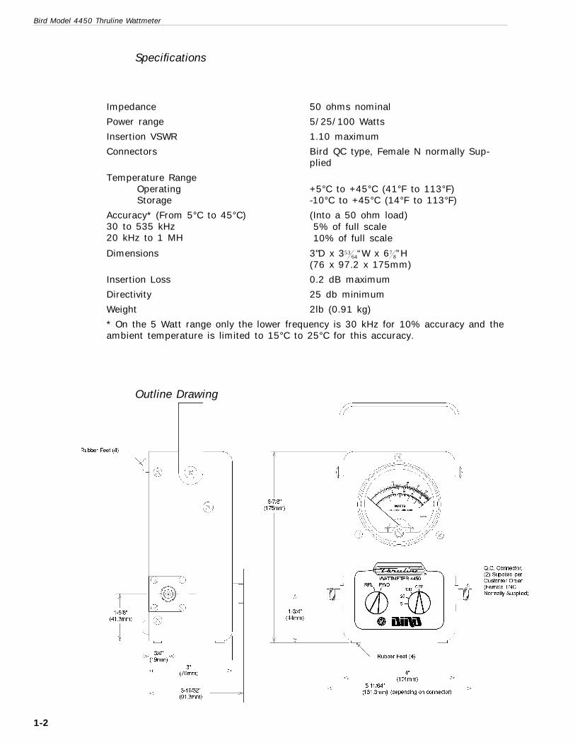
Spec i fi ca tions
Im ped ance 50 ohms nom i nal
Power range 5/25/100 Watts
In ser tion VSWR 1.10 max i mum
Con nec tors Bird QC type, Fe male N nor mally Sup -plied
Tem per a ture RangeOp er atingStor age
+5°C to +45°C (41°F to 113°F)-10°C to +45°C (14°F to 113°F)
Ac cu racy* (From 5°C to 45°C)30 to 535 kHz20 kHz to 1 MHz
(Into a 50 ohm load)5% of full scale10% of full scale
Di men sions 3"D x 35364“W x 67
8”H(76 x 97.2 x 175mm)
In ser tion Loss 0.2 dB max i mum
Directivity 25 db min i mum
Weight 2lb (0.91 kg)
* On the 5 Watt range only the lower fre quency is 30 kHz for 10% ac cu racy and the am bi ent tem per a ture is lim ited to 15°C to 25°C for this ac cu racy.
Out line Draw ing
Bird Model 4450 Thruline Wattmeter
1-2

Sche matic Di a gram
-
1-3

Bird Model 4450 Thruline Wattmeter
1-4
Chap ter 2
The ory Of Op er a tion
Traveling WaveConcept
The op er a tion of the Model 4450 Wattmeter is based on the trav el ing wave con cept of RF trans -mis sion. As RF power is ap plied to a trans mis sion line, there is a for ward wave trav el ing from thetrans mit ter to the load, and a re flected wave trav el ing from the load to the trans mit ter. The closerthe load is matched to the line, the smaller the re flected wave will be. To de ter mine the watts dis -si pated in the load it is nec es sary to de ter mine the power of the for ward wave and the power of the re flected wave. The dif fer ence be tween the two will in di cate ef fec tive power dis si pa tion.
Traveling Wave vsStanding Wave
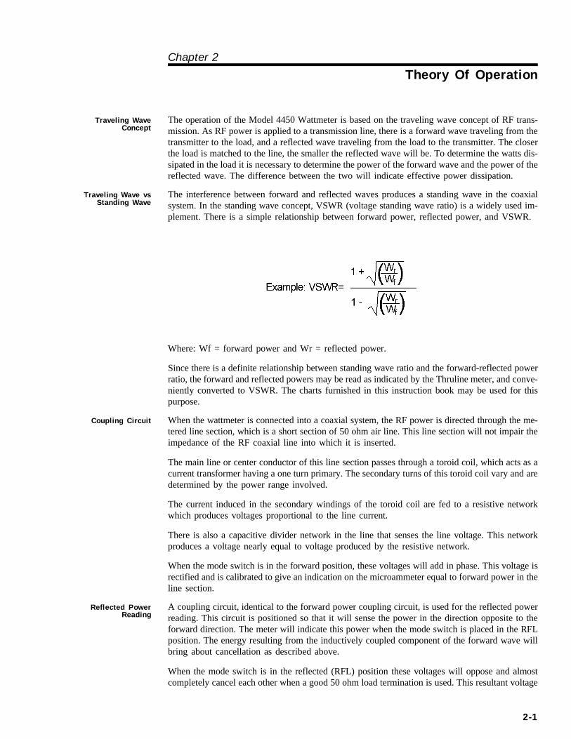
The in ter fer ence be tween for ward and re flected waves pro duces a stand ing wave in the co ax ialsys tem. In the stand ing wave con cept, VSWR (volt age stand ing wave ra tio) is a widely used im -ple ment. There is a sim ple re la tion ship be tween for ward power, re flected power, and VSWR.
Where: Wf = for ward power and Wr = re flected power.
Since there is a def i nite re la tion ship be tween stand ing wave ra tio and the for ward-reflected powerra tio, the for ward and re flected pow ers may be read as in di cated by the Thruline me ter, and con ve -niently con verted to VSWR. The charts fur nished in this in struc tion book may be used for thispur pose.
Coupling Circuit When the wattmeter is con nected into a co ax ial sys tem, the RF power is di rected through the me -tered line sec tion, which is a short sec tion of 50 ohm air line. This line sec tion will not im pair theim ped ance of the RF co ax ial line into which it is in serted.
The main line or cen ter con duc tor of this line sec tion passes through a toroid coil, which acts as acur rent trans former hav ing a one turn pri mary. The sec ond ary turns of this toroid coil vary and are de ter mined by the power range in volved.
The cur rent in duced in the sec ond ary wind ings of the toroid coil are fed to a re sis tive net workwhich pro duces volt ages pro por tional to the line cur rent.
There is also a ca pac i tive di vider net work in the line that senses the line volt age. This net workpro duces a volt age nearly equal to volt age pro duced by the re sis tive net work.
When the mode switch is in the for ward po si tion, these volt ages will add in phase. This volt age isrec ti fied and is cal i brated to give an in di ca tion on the microammeter equal to for ward power in the line sec tion.
Reflected PowerReading
A cou pling cir cuit, iden ti cal to the for ward power cou pling cir cuit, is used for the re flected powerread ing. This cir cuit is po si tioned so that it will sense the power in the di rec tion op po site to thefor ward di rec tion. The me ter will in di cate this power when the mode switch is placed in the RFLpo si tion. The en ergy re sult ing from the in duc tively cou pled com po nent of the for ward wave willbring about can cel la tion as de scribed above.
When the mode switch is in the re flected (RFL) po si tion these volt ages will op pose and al mostcom pletely can cel each other when a good 50 ohm load ter mi na tion is used. This re sul tant volt age
2-1

will be in di cated on the microammeter as the power op po site to the for ward power, or re flectedpower.
Bird Model 4450 Thruline Wattmeter
2-2
Chap ter 3
In stal la tion
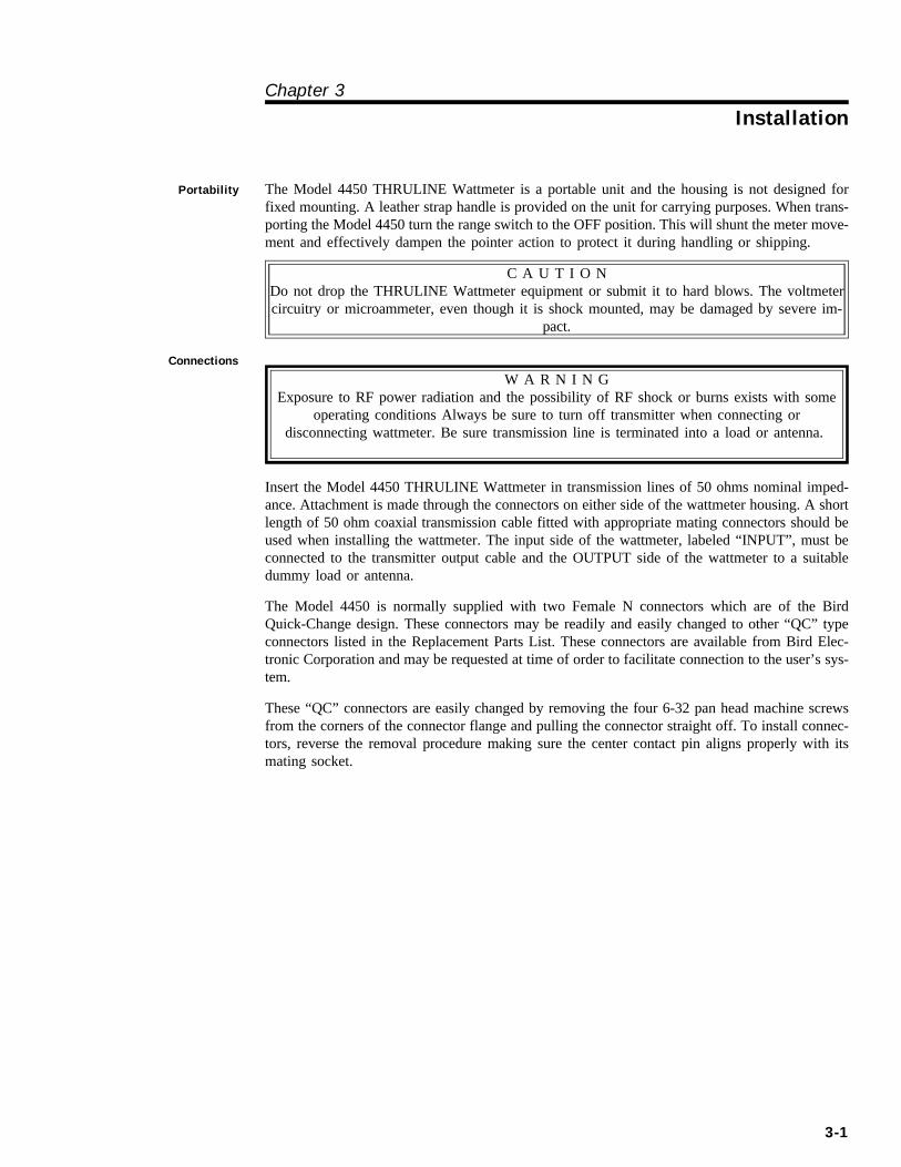
Portability The Model 4450 THRULINE Wattmeter is a por ta ble unit and the hous ing is not de signed forfixed mount ing. A leather strap han dle is pro vided on the unit for car ry ing pur poses. When trans -port ing the Model 4450 turn the range switch to the OFF po si tion. This will shunt the me ter move -ment and ef fec tively dampen the pointer ac tion to pro tect it dur ing han dling or ship ping.
C A U T I O NDo not drop the THRULINE Wattmeter equip ment or sub mit it to hard blows. The volt me ter cir cuitry or microammeter, even though it is shock mounted, may be dam aged by se vere im -
pact.
Connections
W A R N I N GExposure to RF power radiation and the possibility of RF shock or burns exists with some
operating conditions Always be sure to turn off transmitter when connecting ordisconnecting wattmeter. Be sure transmission line is terminated into a load or antenna.
In sert the Model 4450 THRULINE Wattmeter in trans mis sion lines of 50 ohms nom i nal im ped -ance. At tach ment is made through the con nec tors on ei ther side of the wattmeter hous ing. A shortlength of 50 ohm co ax ial trans mis sion ca ble fit ted with ap pro pri ate mat ing con nec tors should beused when in stall ing the wattmeter. The in put side of the wattmeter, la beled “IN PUT”, must becon nected to the trans mit ter out put ca ble and the OUT PUT side of the wattmeter to a suit abledummy load or an tenna.
The Model 4450 is nor mally sup plied with two Fe male N con nec tors which are of the BirdQuick-Change de sign. These con nec tors may be readily and eas ily changed to other “QC” typecon nec tors listed in the Re place ment Parts List. These con nec tors are avail able from Bird Elec -tronic Cor po ra tion and may be re quested at time of or der to fa cil i tate con nec tion to the user’s sys -tem.
These “QC” con nec tors are eas ily changed by re mov ing the four 6-32 pan head ma chine screwsfrom the cor ners of the con nec tor flange and pull ing the con nec tor straight off. To in stall con nec -tors, re verse the re moval pro ce dure mak ing sure the cen ter con tact pin aligns prop erly with itsmat ing socket.
3-1

Bird Model 4450 Thruline Wattmeter
3-2
Chap ter 4
Op er ating In struc tions
The ap par ent fea tures of the Thruline equip ment have been dis cussed in the pre ced ing sec tions. As pre vi ously men tioned, no bat ter ies or ex ter nal power source is re quired to op er ate the wattmeter.A suf fi cient amount of power is taken from the RF trans mis sion line to op er ate the unit. Thispower is neg li gi ble and does not af fect the power out put to a no tice able de gree.
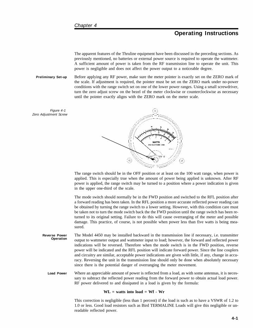
Preliminary Set-up Be fore ap ply ing any RF power, make sure the me ter pointer is ex actly set on the ZERO mark ofthe scale. If ad just ment is re quired, the pointer must be set on the ZERO mark un der no-powercon di tions with the range switch set on one of the lower power ranges. Using a small screw driver,turn the zero ad just screw on the be zel of the me ter clock wise or coun ter clock wise as nec es saryun til the pointer ex actly aligns with the ZERO mark on the me ter scale.
The range switch should be in the OFF po si tion or at least on the 100 watt range, when power isap plied. This is es pe cially true when the amount of power be ing ap plied is un known. Af ter RFpower is ap plied, the range switch may be turned to a po si tion where a power in di ca tion is givenin the up per one-third of the scale.
The mode switch should nor mally be in the FWD po si tion and switched to the RFL po si tion af tera for ward read ing has been taken. In the RFL po si tion a more ac cu rate re flected power read ing can be ob tained by turn ing the range switch to a lower set ting. How ever, with this con di tion care mustbe taken not to turn the mode switch back the the FWD po si tion un til the range switch has been re -turned to its orig i nal set ting. Fail ure to do this will cause overranging of the me ter and pos si bledam age. This prac tice, of course, is not pos si ble when power less than five watts is be ing mea -sured.
Reverse PowerOperation
The Model 4450 may be in stalled back ward in the trans mis sion line if nec es sary, i.e. trans mit terout put to wattmeter out put and wattmeter in put to load; how ever, the for ward and re flected powerin di ca tions will be re versed. There fore when the mode switch is in the FWD po si tion, re versepower will be in di cated and the RFL po si tion will in di cate for ward power. Since the line cou plersand cir cuitry are sim i lar, ac cept able power in di ca tions are given with lit tle, if any, change in ac cu -racy. Re versing the unit in the trans mis sion line should only be done when ab so lutely nec es sarysince there is the po ten tial dan ger of overranging the me ter move ment.
Load Power Where an ap pre cia ble amount of power is re flected from a load, as with some an ten nas, it is nec es -sary to sub tract the re flected power read ing from the for ward power to ob tain ac tual load power.RF power de liv ered to and dis si pated in a load is given by the for mula:
WL = watts into load = Wf - Wr
This cor rec tion is neg li gi ble (less than 1 per cent) if the load is such as to have a VSWR of 1.2 to1.0 or less. Good load re sis tors such as Bird TERMALINE Loads will give this neg li gi ble or un -read able re flected power.
4-1
Figure 4-1Zero Ad just ment Screw

VSWR Calculations Af ter ob tain ing the for ward and re flected power read ings de scribed above, the VSWR may befound by cal cu la tion as de scribed on page 2-1 Traveling wave vs. Stand ing wave. Con ver sionnomographs to sim plify de ter min ing VSWR are pro vided be low. Sim ply find the num bers on thehor i zon tal and ver ti cal axis of the nomograph which cor re spond to the ac tual for ward and re versepower read ings re spec tively. Fol low the cross lines un til they in ter sect, and read the VSWR fromthe near est slanted line.
Bird Model 4450 Thruline Wattmeter
4-2
Figure 4-2VSWR Con ver sion
Mono graphPower Values vs.
VSWR

C h a p t e r 5
Main te nance
Gen eral
This chap ter con tains op er a tor main te nance in struc tions, trou ble shoot ing and parts in for ma tion.
With the rel a tively sim ple cir cuitry, con struc tion, and self-contained na ture of the Model 4450Thruline equip ment, only a mod er ate amount of main te nance is re quired. The ma jor pre cau tion for the safe keep ing and main te nance of the wattmeter is han dling; use rea son able care and do not drop the unit.
Any main te nance or ser vice pro ce dure be yond the scope of those pro vided in this sec tion shouldbe re ferred to a qual i fied ser vice cen ter.
Sales / RepairFacilities
U.S.A. Sales and Man u fac turing
Ser vice GroupBird Elec tronic Cor po ra tion30303 Au rora RoadCleve land (Solon), Ohio 44139-2794Phone: (440) 248-1200 Ca ble: BIRDELECFax: (440) 248-5426 Telex: 706898 Bird Elec UD
Sales Facilities For the lo ca tion of the sales of fice near est you, give us a call or visit our Web site at:
http://www.bird-electronic.com
5-1
Pre ven tive Main te nance
W A R N I N GProvide adequate ventilation and observe normal precautions when using dry cleaning
solvents. Many dry cleaning agents emit toxic fumes that may be harmful to your health ifinhaled. Avoid excessive skin contact or inhalation of the fumes when using any dry
cleaning solvent
If any of the con tacts or line con nec tors be come dirty, they should be cleaned with an aero sol typecleaner that leaves no res i due, or any dry clean ing sol vent on a soft cloth or cot ton swab stick.Clean all con tact sur faces and the ex posed sur face of the Tef lon in su la tors.
The hous ing and me ter glass can be cleaned with a soft cloth and a mild de ter gent so lu tion.
CAU TIONClean the me ter glass only when nec es sary and be care ful not to use an ex ces sive amount of
wa ter/de ter gent so lu tion that might drip in side the hous ing and dam age the elec tri calcom po nents.
Trou ble shooting
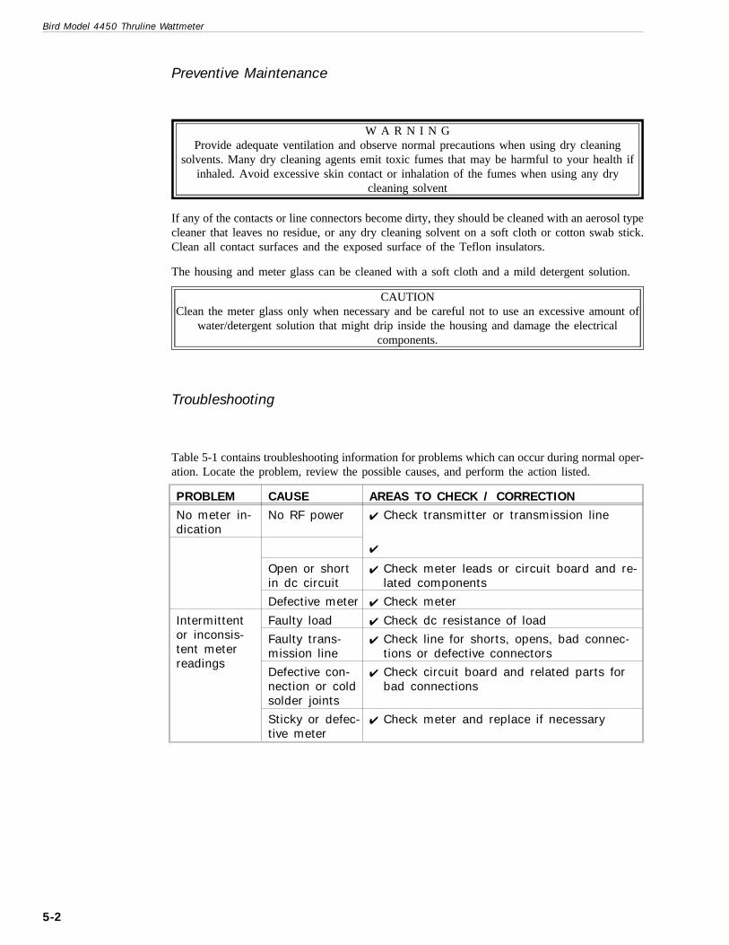
Ta ble 5-1 con tains trou ble shoot ing in for ma tion for prob lems which can oc cur dur ing nor mal op er -a tion. Lo cate the prob lem, re view the pos si ble causes, and per form the ac tion listed.
Bird Model 4450 Thruline Wattmeter
5-2
PROB LEM CAUSE AREAS TO CHECK / COR REC TION
No me ter in -di ca tion
No RF power 4 Check trans mit ter or trans mis sion line
4
Open or shortin dc cir cuit
4 Check me ter leads or cir cuit board and re -lated com po nents
De fec tive me ter 4 Check me ter
In ter mit tentor in con sis -tent me terread ings
Faulty load 4 Check dc re sis tance of load
Faulty trans -mis sion line
4 Check line for shorts, opens, bad con nec -tions or de fec tive con nec tors
De fec tive con -nec tion or cold sol der joints
4 Check cir cuit board and re lated parts forbad con nec tions
Sticky or de fec -tive me ter
4 Check me ter and re place if nec es sary
Re pair
Al though the Model 4450 is de signed to be rug ged and pro vide years of trou ble-free ser vice, oc ca -sional re pair or re place ment may be come nec es sary. This sec tion con tains re pair and re place mentpro ce dures.
Re pairs should not be at tempted by the user for the first year war ranty pe riod as this may void thewar ranty.
If a prob lem should oc cur in the line sec tion or cou pling cir cuits, the unit should be re turned to the fac tory for re pair and recalibration.
Remove Back Cover Fol low the in struc tions be low when re mov ing the back cover is nec es sary for parts re place ment or re pair.
1. With draw four screws lo cated on the back half of both sides.
2. Pull back cover straight off.
Circuit Board Repairor Replacement
1. Re move back cover.
2. Peel off the rub ber feet lo cated in the back half of the bot tom sec -tion to gain ac cess to flat head screws se cur ing the line sec tionmount ing bracket.
3. Re move the two screws.
4. Pull the line sec tion out of the back slightly and dis con nect thethree wires that con nect to the cir cuit board.
5. With draw four pan head screws in each cor ner of con nec tor flangesand pull QC con nec tors straight off.
6. With draw the four screws on the line sec tion hous ing po si tionednear the top edge. Do not re move the screws that se cure the mount -ing bracket to the hous ing. The cir cuit board will lift straight out ofthe hous ing with the cen ter con duc tor at tached.
7. Com plete re as sem bly by re vers ing the pro ce dure above. See note be -low.
+ NOTE: When re as sem bling the cir cuit board and line sec tion in the hous ing, po si tion the cir -cuit board so that the 5k cal i brat ing po ten ti om eters, R5 and R6, face away from the side of the hous ing on which the mount ing bracket is at tached. These con trols must face out ward for cal i -bra tion pur poses and also to main tain cor rect in put and out put con fig u ra tion.
Calibration Board and Meter Removal
1. Re move the rear cover.
2. Un plug the rib bon ca ble con nec tor from the cal i bra tion board.
3. Re move the two nuts that se cure the cal i bra tion board to the ter mi -nals of the me ter. The cal i bra tion board can now be taken out of the hous ing.
4. To re move the me ter, un screw the three Phil lips head screws fromthe front face of the me ter hous ing. The me ter may now be pulledstraight out of the hous ing. No tice the rub ber shock ring on thefront of the me ter. It must be re placed when re as sem bling me ter tocase.
-
5-3
5. Re in stall the me ter and cal i bra tion board by re vers ing the dis as sem -bly pro ce dure. Do not tighten the me ter mount ing screws ex ces -sively.
Range and ModeSwitch Replacement
1. Re move back cover.
2. Peel off the rub ber feet lo cated in the back half of the bot tom sec -tion to gain ac cess to flat head screws se cur ing the line sec tionmount ing bracket.
3. Re move the two screws.
4. Pull the line sec tion out of the back slightly and dis con nect thethree wires that con nect to the cir cuit board.
5. Using a 5/64 Al len wrench, loosen the set screws in the switchknobs and re move the knobs.
6. Re move the nuts that se cure the switches to the front panel with a9/16 end wrench. Un plug the rib bon ca ble con nec tor from the cal i -bra tion board. The switch and ca ble har ness as sem bly can now bere moved from the me ter hous ing as sem bly for re pair or re place ment. If only one switch is to be re placed, be sure to re at tach the wiresin di vid u ally to the cor rect switch lugs as orig i nal.
7. To re in stall the switch as sem bly, sim ply re verse the dis as sem blypro ce dure. When re plac ing the knobs, make sure the ar row of theknob points to the cor rect set ting be fore tight en ing the set screws.
Bird Model 4450 Thruline Wattmeter
5-4

Re place ment Parts List
Q T Y . D E S C R I P T I O N P A R T N U M B E R
1 Line sec tion as sem bly 4450-003
1 Mount ing bracket 450-020
2 PC board mount ing brack ets 4450-019
1 30 uA me ter 2080-063
2 Switch knobs 4110-016
1 Me ter hous ing 4450-009
1 Carrying strap 8580-003
8 Bumper feet 5-875
1 Back cover as sem bly 4450-005
2 “QC” con nec tors *See Be low
1 PC board as sem bly (line sec tion) 4450-015
1 PC board as sem bly (me ter) 4450-014
2 RF choke (2.4 uH) (L1 & L2) 5-1546
1 Switch (2 pole, 2 po si tion) 5-1361
1 Switch (2 pole, 4 po si tion) 4450-026
2 N617 di odes (RCA SK3087) (D1 & D2) 5-1571
2 25 k po ten ti om eters (R1 & R3) 5-1364-2
2 100 k po ten ti om eters (R2 & R4) 5-1364-5
2 5k po ten ti om eters (R5 & R6) 5-1572
2 13 ohm (R7 & R8) 5-581
1 1.8 k sensistor (SR1) 5-595-1
1 5 k sensistors (SR3) 5-595-7
1 10 k sensistor (SR2) 5-595-8
2 1000pF ce ramic (C1 & C2) 5-1564-1
2 5000pF ce ramic (C3 & C6) 5-1564-2
2 15-60pF vari able (C4 & C5) 5-1570
1 Switch as sem bly (In cludes bothswitches & wire har ness) 4450-004
*Avail able “QC” Type Con nec tors
N-Female 4240-062 LT-Female 4240-018
N-Male 4240-063 LT-Male 4240-012
HN-Female 4240-268 C-Female 4240-100
HN-Male 4240-278 C-Male 4240-110
LC-Female 4240-031 UHF-Female (SO-239) 4240-050
LC-Male 4240-025 UHF-Male (PL-259) 4240-179
BNC-Female 4240-125 7/8" EIA Air Line 4240-002
BNC-Male 4240-132
-
5-5


QUAL ITY IN STRU MENTSFOR RF POWER MEASUEMENT
From 2 to 2300 MHz and from 25 milliwattsto 250 ki lo watts in 50 ohm co ax ial line sys tems
TERMALINE®
AB SORP TIONWATT ME TERS
LOAD RE SIS TORS
CAL O RIM E TERS
THRULINE®
DI REC TIONALMON I TORINGWATT ME TERS
TENULINE®
ATTENUATORS
COAXWITCH®
SE LEC TORSWITCHES
CO AX IAL RF FIL TERS
SENTRILINE®
FIL TER-COUPLERS
E L E C T R O N I C C O R P O R A T I O N
30303 Au rora Road, Cleve land, (Solon) Ohio 44139-2794