indestructible - industricals.com · 4 service contact persons at mennekes india receptacles plugs...
TRANSCRIPT

India

Indestructible
„Without compromise. For toughest conditions!“
PowerTOP Xtraplugs and connecors:Extra slip-proof.Extra shock-resistant.Extra protected.
Serv
ice
Rece
ptac
les
Plug
s an
d co
nnec
tors
Rece
ptac
le c
ombi
natio
nsSp
ecic
al p
lugs
and
soc
kets
, ac
cess
orie
s
Receptacles
Plugs and connectors
Receptacle combinations
ServiceYour contact at MENNEKES India 4 - 5 About us 6 - 9 Drawings and Dimensions 10 - 19Index of part numbers 82 - 83
Product information 20 - 21Wall mounted receptacles 22 - 23Wall mounted receptacles switched and interlocked or fused 24 - 25 Wall mounted receptacles switched, interlocked and fused 26 Receptacles, high resistance to chemicals, made of AMELAN 27Receptacles Cepex 28Panel mounted receptacles 29 - 32Panel mounted receptacles, switched and interlocked 33
Product information 34 - 35Plugs 36 - 37Wall mounted inlets 38Panel mounted inlets 39 - 40 Phase sequence test plugs 41 Phase inverter plugs 42Wall and panel mounted phase inverter inlets 43 Connectors 44 - 45
Product information 46 - 51AMAXX® receptacle combinations, made of AMAPLAST 52 - 61AMAXX® receptacle combinations, high resistance to chemicals, made of AMELAN 62 - 633KRAFT and AirKRAFT receptacle combinations 64DELTA-BOXES and receptacle strips 65 EverGUM receptacle combinations 66 Steel and stainless steel receptacle combinations 67
Product information 68 - 69SCHUKO® and grounding-type plugs and sockets 70 - 72Plugs and sockets 200A up to 400A 73Plugs and sockets for reefer containers 74 - 76Data port sockets 77Plugs and sockets for low voltage 78 - 79CEE plugs and sockets for hazardous areas, Ex zone 22 80Switch Disconnectors 81
Special plugs and sockets, accessories
4
Serv
ice
Contact persons at MENNEKES IndiaRe
cept
acle
sPl
ugs
and
conn
ecto
rsRe
cept
acle
com
bina
tions
Spec
ical
plu
gs a
nd s
ocke
ts,
acce
ssor
ies
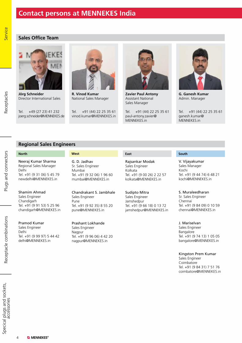
Sales Office Team
G. Ganesh Kumar Admin. Manager
Tel. +91 (44) 22 25 35 61ganesh.kumar@ MENNEKES.in
Zavier Paul Antony Assistant National Sales Manager
Tel. +91 (44) 22 25 35 61 paul-antony.zavier@ MENNEKES.in
R. Vinod Kumar National Sales Manager
Tel. +91 (44) 22 25 35 [email protected]
Jörg Schneider Director International Sales
Tel. +49 (27 23) 41 [email protected]
Regional Sales Engineers
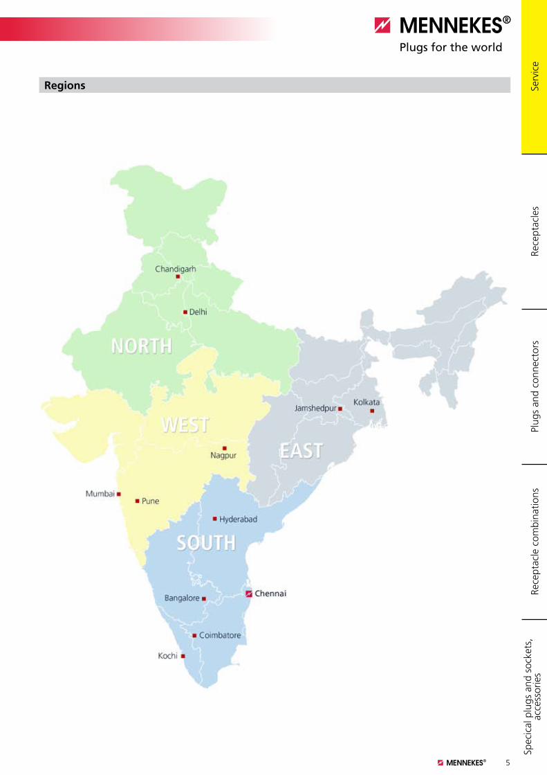
North East SouthWest
Neeraj Kumar Sharma Regional Sales Manager DelhiTel. +91 (9 31 06) 5 45 [email protected]
Shamim Ahmad Sales Engineer ChandigarhTel. +91 (9 91 53) 5 25 [email protected]
Pramod Kumar Sales Engineer DelhiTel. +91 (9 99 97) 5 44 [email protected]
G. D. JadhavSr. Sales Engineer MumbaiTel. +91 (9 32 06) 1 96 [email protected]
Chandrakant S. JambhaleSales Engineer PuneTel. +91 (9 92 35) 8 55 [email protected]
Prashant LokhandeSales Engineer NagpurTel. +91 (9 96 06) 4 42 [email protected]
Rajsankar ModakSales Engineer KolkataTel. +91 (9 00 26) 2 22 [email protected]
Sudipto MitraSales Engineer JamshedpurTel. +91 (9 66 18) 0 13 72 [email protected]
V. VijayakumarSales Manager KochiTel. +91 (9 44 74) 6 48 [email protected]
S. MuraleedharanSr. Sales Engineer ChennaiTel. +91 (9 84 09) 0 10 [email protected]
J. MariselvanSales Engineer BangaloreTel. +91 (9 74 13) 1 05 [email protected]
Kingston Prem KumarSales Engineer CoimbatoreTel. +91 (9 84 31) 7 51 [email protected]
Serv
ice
5
Contact persons at MENNEKES India
Rece
ptac
les
Plug
s an
d co
nnec
tors
Rece
ptac
le c
ombi
natio
nsSp
ecic
al p
lugs
and
soc
kets
, ac
cess
orie
s
Regions

6
Serv
ice
About us
“Our brand is a promise.“ Andreas Sprecker, Managing Director, Sales and Marketing
Quality, reliability,innovation,marketability,sustainability.
Rece
ptac
les
Plug
s an
d co
nnec
tors
Rece
ptac
le c
ombi
natio
nsSp
ecic
al p
lugs
and
soc
kets
, ac
cess
orie
s

Serv
ice
7
About us
Unmistakable
For 75 years the MENNEKES name has been
the byword for unmistakable products in the
markets of the world.
Every expert and end user in the electrical
industry knows: Only those products which
have the MENNEKES brand name on, con-
tain MENNEKES quality.
We give you a promise of quality and service.
This promise is one of the main reasons
why our family-owned company has a
brand which is irreplaceable. We live our
brand and feel obliged to it. You can rely on
MENNEKES. This is and remains the driving
force of our 900 employees worldwide. It
is through their daily dedication where they
prove their commitment to the MENNEKES
brand, whether it is in Germany, in Great
Britain or in any other part of the world.
Highest quality, reliability, safety, power of
innovation, marketability and sustainability
of our action form our brand.
We have a clear identity which makes
MENNEKES the ideal partner for you, our
customers and the end user, being a reliable
supplier of an irreplaceable brand.
Kirchhundem headquarters
Rece
ptac
les
Plug
s an
d co
nnec
tors
Rece
ptac
le c
ombi
natio
nsSp
ecic
al p
lugs
and
soc
kets
, ac
cess
orie
s

8
Serv
ice
Any time. In any situation. All over theworld.
Endurance test
When a MENNEKES product leaves our works, it has already survived the harshest testing. In our test lab it is exposed to cold, heat, dust and water over and over again. Only the products that withstand these tests are worthy of the name MENNEKES.
As a specialist for plug and socket devices, we have our own approved test lab where our products are tested again and again. As long as it takes, until we are convinced that they can permanently withstand the harshest requirements of the everyday working environment.
Our products are of course certified to national and inter-national standards by renowned institutions. Like the MENNEKES company itself: Our international quality management system is certified to DIN EN ISO 9001.
Only the combination of first-class raw materials and advanced manufacturing processes guarantees a premium product. This is why we use only first-grade granules which are processed by a highly skilled workforce in state-of-the-art production facilities to create certified MENNEKES products.
About usRe
cept
acle
sPl
ugs
and
conn
ecto
rsRe
cept
acle
com
bina
tions
Spec
ical
plu
gs a
nd s
ocke
ts,
acce
ssor
ies
Serv
ice
9
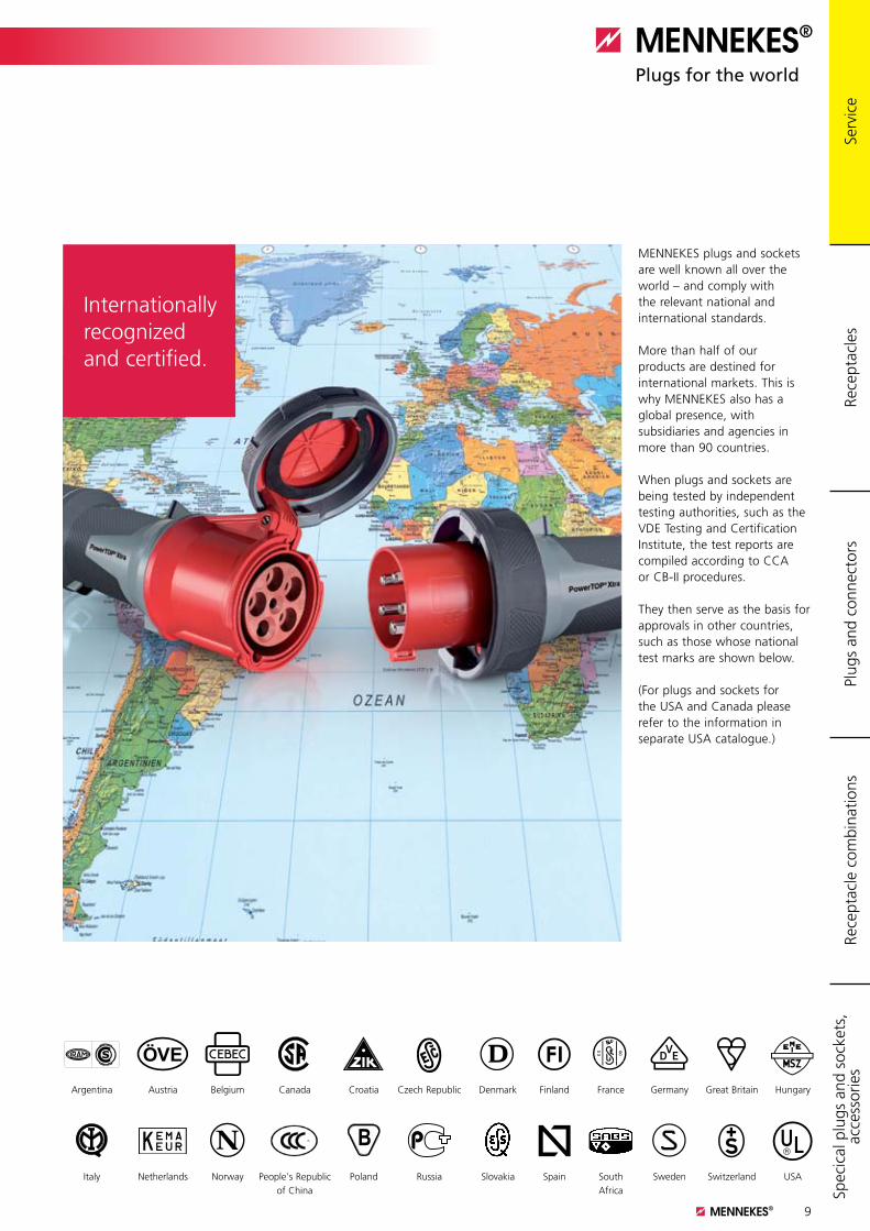
Internationally recognized and certified.
MENNEKES plugs and sockets are well known all over the world – and comply with the relevant national and international standards.
More than half of our products are destined for international markets. This is why MENNEKES also has a global presence, with subsidiaries and agencies in more than 90 countries.
When plugs and sockets are being tested by independent testing authorities, such as the VDE Testing and Certification Institute, the test reports are compiled according to CCA or CB-II procedures.
They then serve as the basis for approvals in other countries, such as those whose national test marks are shown below.
(For plugs and sockets for the USA and Canada please refer to the information in separate USA catalogue.)
Argentina Austria Belgium Canada Croatia Czech Republic Denmark Finland France Germany Great Britain Hungary
Italy Netherlands Norway People's Republic of China
Poland Russia Slovakia Spain South Africa
Sweden Switzerland USA
About us
Rece
ptac
les
Plug
s an
d co
nnec
tors
Rece
ptac
le c
ombi
natio
nsSp
ecic
al p
lugs
and
soc
kets
, ac
cess
orie
s
10
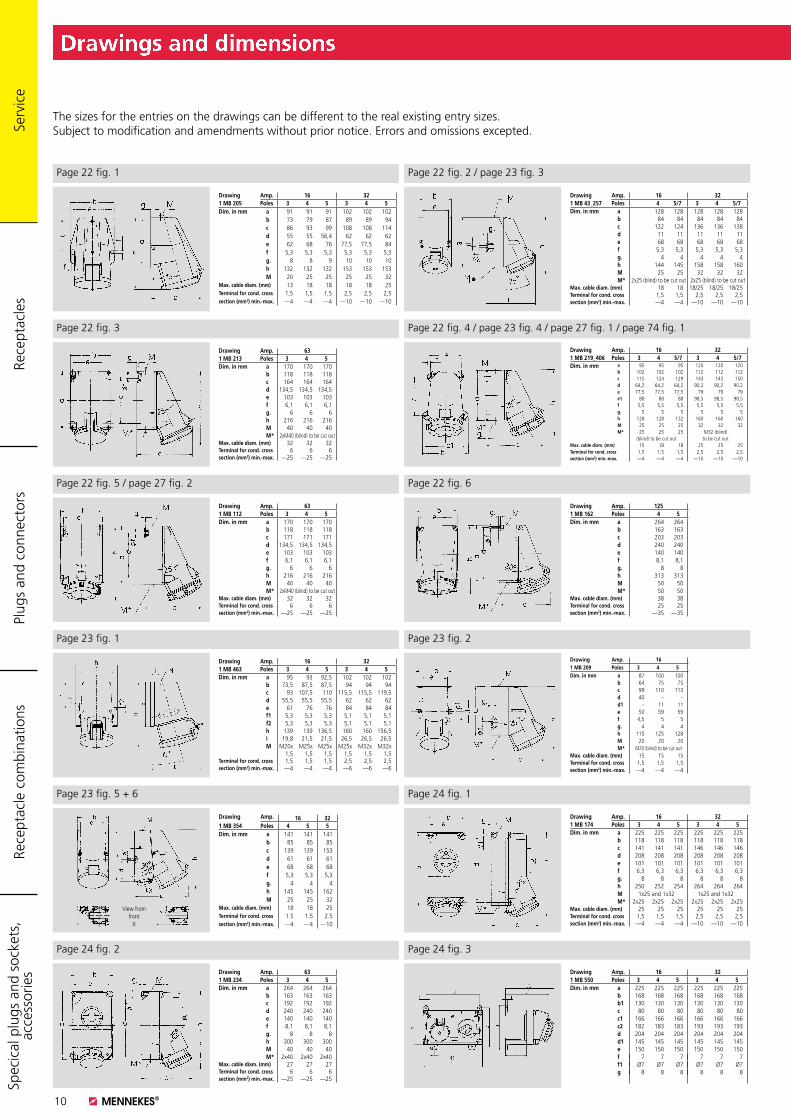
Drawings and dimensions
Page 22 fig. 1
Drawing Amp. 161 MB 209 Poles 3 4 5Dim. in mm a 87 100 100
b 64 75 75c 99 110 113d 40 – –d1 – 11 11e 50 59 59f 4,5 5 5g. 4 4 4h 115 125 128M 20 20 20M* M20 (blind) to be cut out
Max. cable diam. (mm) 15 15 15Terminal for cond. cross 1,5 1,5 1,5section (mm2) min.-max. —4 —4 —4
Drawing Amp. 16 321 MB 463 Poles 3 4 5 3 4 5Dim. in mm a 95 93 92,5 102 102 102
b 73,5 87,5 87,5 94 94 94c 93 107,5 110 115,5 115,5 119,5d 55,5 55,5 55,5 62 62 62e 61 76 76 84 84 84f1 5,3 5,3 5,3 5,1 5,1 5,1f2 5,3 5,3 5,3 5,1 5,1 5,1h 139 139 136,5 160 160 156,5i 19,8 21,5 21,5 26,5 26,5 26,5M M20x M25x M25x M25x M32x M32x
1,5 1,5 1,5 1,5 1,5 1,5Terminal for cond. cross 1,5 1,5 1,5 2,5 2,5 2,5section (mm2) min.-max. —4 —4 —4 —6 —6 —6
Page 22 fig. 2 / page 23 fig. 3
Page 22 fig. 3
Drawing Amp. 16 321 MB 219_406 Poles 3 4 5/7 3 4 5/7Dim. in mm a 95 95 95 120 120 120
b 102 102 102 112 112 112c 115 124 129 143 143 150d 64,2 64,2 64,2 90,2 90,2 90,2e 77,5 77,5 77,5 79 79 79e1 88 88 88 98,5 98,5 98,5f 5,5 5,5 5,5 5,5 5,5 5,5g. 5 5 5 5 5 5h 128 128 132 160 160 160M 25 25 25 32 32 32M* 25 25 25 M32 (blind)
(blind) to be cut out to be cut outMax. cable diam. (mm) 15 18 18 25 25 25Terminal for cond. cross 1,5 1,5 1,5 2,5 2,5 2,5section (mm2) min.-max. —4 —4 —4 —10 —10 —10
Drawing Amp. 16 321 MB 43_257 Poles 4 5/7 3 4 5/7Dim. in mm a 128 128 128 128 128
b 84 84 84 84 84c 122 124 136 136 138d 11 11 11 11 11e 68 68 68 68 68f 5,3 5,3 5,3 5,3 5,3g. 4 4 4 4 4h 144 145 158 158 160M 25 25 32 32 32M* 2x25 (blind) to be cut out 2x25 (blind) to be cut out
Max. cable diam. (mm) 18 18 18/25 18/25 18/25Terminal for cond. cross 1,5 1,5 2,5 2,5 2,5section (mm2) min.-max. —4 —4 —10 —10 —10
Page 22 fig. 4 / page 23 fig. 4 / page 27 fig. 1 / page 74 fig. 1
Page 22 fig. 5 / page 27 fig. 2 Page 22 fig. 6
Page 23 fig. 1 Page 23 fig. 2
Page 23 fig. 5 + 6 Page 24 fig. 1
Page 24 fig. 2 Page 24 fig. 3
Drawing Amp. 1251 MB 162 Poles 4 5Dim. in mm a 264 264
b 163 163c 203 203d 240 240e 140 140f 8,1 8,1g. 8 8h 313 313M 50 50M* 50 50
Max. cable diam. (mm) 38 38Terminal for cond. cross 25 25section (mm2) min.-max. —35 —35
Drawing Amp. 631 MB 112 Poles 3 4 5Dim. in mm a 170 170 170
b 118 118 118c 171 171 171d 134,5 134,5 134,5e 103 103 103f 6,1 6,1 6,1g. 6 6 6h 216 216 216M 40 40 40M* 2xM40 (blind) to be cut out
Max. cable diam. (mm) 32 32 32Terminal for cond. cross 6 6 6section (mm2) min.-max. —25 —25 —25
Drawing Amp. 631 MB 213 Poles 3 4 5Dim. in mm a 170 170 170
b 118 118 118c 164 164 164d 134,5 134,5 134,5e 103 103 103f 6,1 6,1 6,1g. 6 6 6h 216 216 216M 40 40 40M* 2xM40 (blind) to be cut out
Max. cable diam. (mm) 32 32 32Terminal for cond. cross 6 6 6section (mm2) min.-max. —25 —25 —25
Drawing Amp. 16 321 MB 205 Poles 3 4 5 3 4 5Dim. in mm a 91 91 91 102 102 102
b 73 79 87 89 89 94c 86 93 99 108 108 114d 55 55 56,4 62 62 62e 62 68 76 77,5 77,5 84f 5,3 5,3 5,3 5,3 5,3 5,3g. 8 8 9 10 10 10h 132 132 132 153 153 153M 20 25 25 25 25 32
Max. cable diam. (mm) 13 18 18 18 18 25Terminal for cond. cross 1,5 1,5 1,5 2,5 2,5 2,5section (mm2) min.-max. —4 —4 —4 —10 —10 —10
The sizes for the entries on the drawings can be different to the real existing entry sizes. Subject to modification and amendments without prior notice. Errors and omissions excepted.
Rece
ptac
les
Plug
s an
d co
nnec
tors
Rece
ptac
le c
ombi
natio
nsSp
ecic
al p
lugs
and
soc
kets
, ac
cess
orie
s
Drawing Amp. 16 321 MB 354 Poles 4 5 5Dim. in mm a 141 141 141
b 85 85 85c 139 139 153d 61 61 61e 68 68 68f 5,3 5,3 5,3g. 4 4 4h 145 145 162M 25 25 32
Max. cable diam. (mm) 18 18 25Terminal for cond. cross 1.5 1.5 2.5section (mm2) min.-max. —4 —4 —10
View fromfront
X
Drawing Amp. 16 321 MB 174 Poles 3 4 5 3 4 5Dim. in mm a 225 225 225 225 225 225
b 118 118 118 118 118 118c 141 141 141 146 146 146d 208 208 208 208 208 208e 101 101 101 101 101 101f 6,3 6,3 6,3 6,3 6,3 6,3g. 8 8 8 8 8 8h 250 252 254 264 264 264M 1x25 and 1x32 1x25 and 1x32M* 2x25 2x25 2x25 2x25 2x25 2x25
Max. cable diam. (mm) 25 25 25 25 25 25Terminal for cond. cross 1,5 1,5 1,5 2,5 2,5 2,5section (mm2) min.-max. —4 —4 —4 —10 —10 —10
Drawing Amp. 631 MB 234 Poles 3 4 5Dim. in mm a 264 264 264
b 163 163 163c 192 192 192d 240 240 240e 140 140 140f 8,1 8,1 8,1g. 8 8 8h 300 300 300M 40 40 40M* 2x40 2x40 2x40
Max. cable diam. (mm) 27 27 27Terminal for cond. cross 6 6 6section (mm2) min.-max. —25 —25 —25
Drawing Amp. 16 321 MB 550 Poles 3 4 5 3 4 5Dim. in mm a 225 225 225 225 225 225
b 168 168 168 168 168 168b1 130 130 130 130 130 130c 80 80 80 80 80 80c1 166 166 166 166 166 166c2 182 183 183 193 193 193d 204 204 204 204 204 204d1 145 145 145 145 145 145e 150 150 150 150 150 150f 7 7 7 7 7 7f1 Ø7 Ø7 Ø7 Ø7 Ø7 Ø7g 8 8 8 8 8 8
Serv
ice
11
Drawings and dimensions
Page 26 fig. 3-5 / page 27 fig. 5 / page 74 fig. 3Page 26 fig. 1 + 2
Page 28 fig. 1 Page 28 fig. 2
Page 28 fig. 3 Page 28 fig. 4
Page 28 fig. 5 Page 28 fig. 6 / page 77 fig. 1
Page 25 fig. 2 / page 27 fig. 4Page 25 fig. 1 / page 27 fig. 3 / page 74 fig. 2
Page 25 fig. 3 / page 26 fig. 6 Page 25 fig. 4
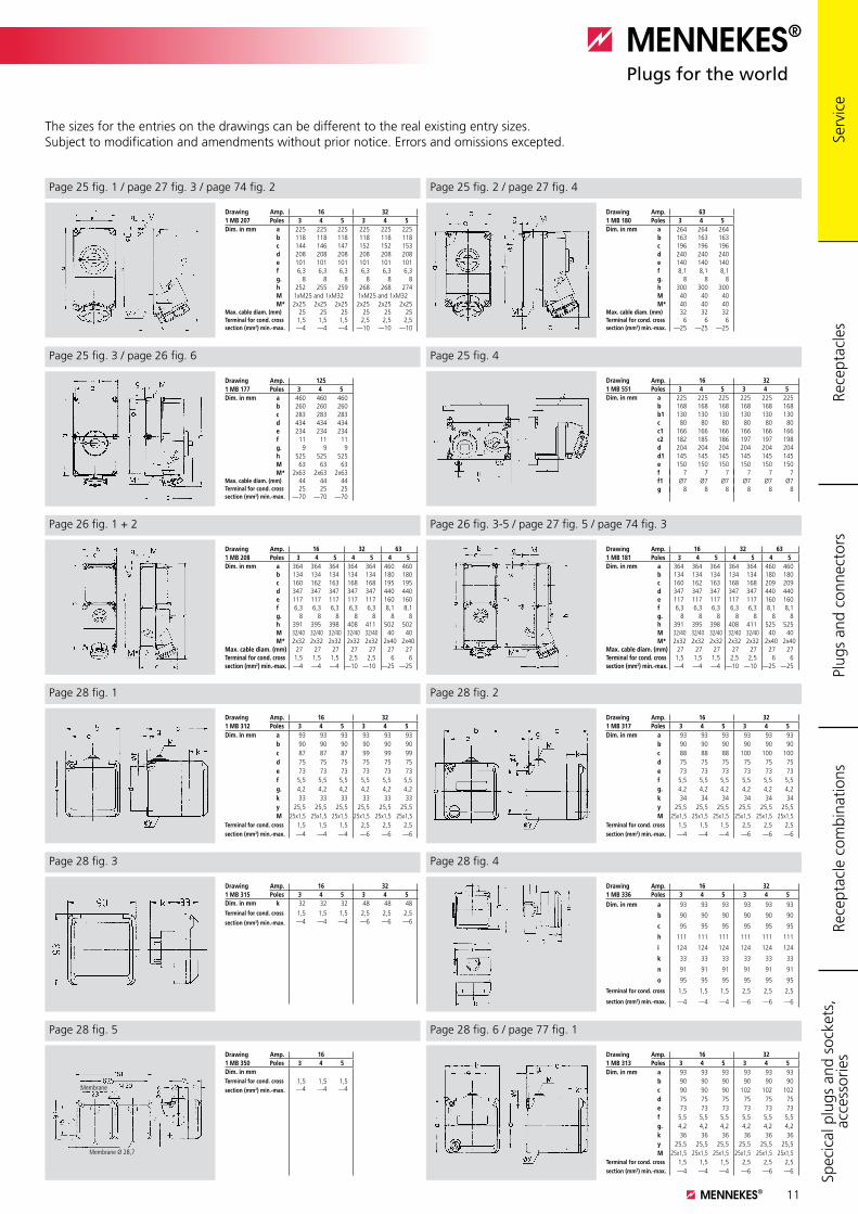
The sizes for the entries on the drawings can be different to the real existing entry sizes. Subject to modification and amendments without prior notice. Errors and omissions excepted.
Rece
ptac
les
Plug
s an
d co
nnec
tors
Rece
ptac
le c
ombi
natio
nsSp
ecic
al p
lugs
and
soc
kets
, ac
cess
orie
s
Drawing Amp. 16 321 MB 207 Poles 3 4 5 3 4 5Dim. in mm a 225 225 225 225 225 225
b 118 118 118 118 118 118c 144 146 147 152 152 153d 208 208 208 208 208 208e 101 101 101 101 101 101f 6,3 6,3 6,3 6,3 6,3 6,3g. 8 8 8 8 8 8h 252 255 259 268 268 274M 1xM25 and 1xM32 1xM25 and 1xM32M* 2x25 2x25 2x25 2x25 2x25 2x25
Max. cable diam. (mm) 25 25 25 25 25 25Terminal for cond. cross 1,5 1,5 1,5 2,5 2,5 2,5section (mm2) min.-max. —4 —4 —4 —10 —10 —10
Drawing Amp. 631 MB 180 Poles 3 4 5Dim. in mm a 264 264 264
b 163 163 163c 196 196 196d 240 240 240e 140 140 140f 8,1 8,1 8,1g. 8 8 8h 300 300 300M 40 40 40M* 40 40 40
Max. cable diam. (mm) 32 32 32Terminal for cond. cross 6 6 6section (mm2) min.-max. —25 —25 —25
Drawing Amp. 1251 MB 177 Poles 3 4 5Dim. in mm a 460 460 460
b 260 260 260c 283 283 283d 434 434 434e 234 234 234f 11 11 11g. 9 9 9h 525 525 525M 63 63 63M* 2x63 2x63 2x63
Max. cable diam. (mm) 44 44 44Terminal for cond. cross 25 25 25section (mm2) min.-max. —70 —70 —70
Drawing Amp. 16 321 MB 551 Poles 3 4 5 3 4 5Dim. in mm a 225 225 225 225 225 225
b 168 168 168 168 168 168b1 130 130 130 130 130 130c 80 80 80 80 80 80c1 166 166 166 166 166 166c2 182 185 186 197 197 198d 204 204 204 204 204 204d1 145 145 145 145 145 145e 150 150 150 150 150 150f 7 7 7 7 7 7f1 Ø7 Ø7 Ø7 Ø7 Ø7 Ø7g 8 8 8 8 8 8
Drawing Amp. 16 32 631 MB 208 Poles 3 4 5 4 5 4 5Dim. in mm a 364 364 364 364 364 460 460
b 134 134 134 134 134 180 180c 160 162 163 168 168 195 195d 347 347 347 347 347 440 440e 117 117 117 117 117 160 160f 6,3 6,3 6,3 6,3 6,3 8,1 8,1g. 8 8 8 8 8 8 8h 391 395 398 408 411 502 502M 32/40 32/40 32/40 32/40 32/40 40 40M* 2x32 2x32 2x32 2x32 2x32 2x40 2x40
Max. cable diam. (mm) 27 27 27 27 27 27 27Terminal for cond. cross 1,5 1,5 1,5 2,5 2,5 6 6section (mm2) min.-max. —4 —4 —4 —10 —10 —25 —25
Drawing Amp. 16 32 631 MB 181 Poles 3 4 5 4 5 4 5Dim. in mm a 364 364 364 364 364 460 460
b 134 134 134 134 134 180 180c 160 162 163 168 168 209 209d 347 347 347 347 347 440 440e 117 117 117 117 117 160 160f 6,3 6,3 6,3 6,3 6,3 8,1 8,1g. 8 8 8 8 8 8 8h 391 395 398 408 411 525 525M 32/40 32/40 32/40 32/40 32/40 40 40M* 2x32 2x32 2x32 2x32 2x32 2x40 2x40
Max. cable diam. (mm) 27 27 27 27 27 27 27Terminal for cond. cross 1,5 1,5 1,5 2,5 2,5 6 6section (mm2) min.-max. —4 —4 —4 —10 —10 —25 —25
Drawing Amp. 16 321 MB 312 Poles 3 4 5 3 4 5Dim. in mm a 93 93 93 93 93 93
b 90 90 90 90 90 90c 87 87 87 99 99 99d 75 75 75 75 75 75e 73 73 73 73 73 73f 5,5 5,5 5,5 5,5 5,5 5,5g. 4,2 4,2 4,2 4,2 4,2 4,2k 33 33 33 33 33 33y 25,5 25,5 25,5 25,5 25,5 25,5M 25x1,5 25x1,5 25x1,5 25x1,5 25x1,5 25x1,5
Terminal for cond. cross 1,5 1,5 1,5 2,5 2,5 2,5section (mm2) min.-max. —4 —4 —4 —6 —6 —6
Drawing Amp. 16 321 MB 317 Poles 3 4 5 3 4 5Dim. in mm a 93 93 93 93 93 93
b 90 90 90 90 90 90c 88 88 88 100 100 100d 75 75 75 75 75 75e 73 73 73 73 73 73f 5,5 5,5 5,5 5,5 5,5 5,5g. 4,2 4,2 4,2 4,2 4,2 4,2k 34 34 34 34 34 34y 25,5 25,5 25,5 25,5 25,5 25,5M 25x1,5 25x1,5 25x1,5 25x1,5 25x1,5 25x1,5
Terminal for cond. cross 1,5 1,5 1,5 2,5 2,5 2,5section (mm2) min.-max. —4 —4 —4 —6 —6 —6
Drawing Amp. 16 321 MB 315 Poles 3 4 5 3 4 5Dim. in mm k 32 32 32 48 48 48Terminal for cond. cross 1,5 1,5 1,5 2,5 2,5 2,5section (mm2) min.-max. —4 —4 —4 —6 —6 —6
Drawing Amp. 16 321 MB 336 Poles 3 4 5 3 4 5Dim. in mm a 93 93 93 93 93 93
b 90 90 90 90 90 90
c 95 95 95 95 95 95
h 111 111 111 111 111 111
i 124 124 124 124 124 124
k 33 33 33 33 33 33
n 91 91 91 91 91 91
o 95 95 95 95 95 95
Terminal for cond. cross 1,5 1,5 1,5 2,5 2,5 2,5
section (mm2) min.-max. —4 —4 —4 —6 —6 —6
Membrane
Membrane Ø 28,7
Drawing Amp. 161 MB 350 Poles 3 4 5Dim. in mmTerminal for cond. cross 1,5 1,5 1,5section (mm2) min.-max. —4 —4 —4
Drawing Amp. 16 321 MB 313 Poles 3 4 5 3 4 5Dim. in mm a 93 93 93 93 93 93
b 90 90 90 90 90 90c 90 90 90 102 102 102d 75 75 75 75 75 75e 73 73 73 73 73 73f 5,5 5,5 5,5 5,5 5,5 5,5g. 4,2 4,2 4,2 4,2 4,2 4,2k 36 36 36 36 36 36y 25,5 25,5 25,5 25,5 25,5 25,5M 25x1,5 25x1,5 25x1,5 25x1,5 25x1,5 25x1,5
Terminal for cond. cross 1,5 1,5 1,5 2,5 2,5 2,5section (mm2) min.-max. —4 —4 —4 —6 —6 —6
Serv
ice
12
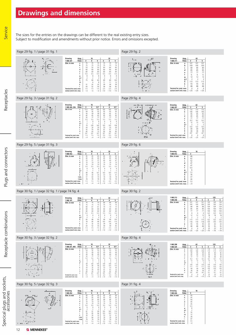
Drawings and dimensions
The sizes for the entries on the drawings can be different to the real existing entry sizes. Subject to modification and amendments without prior notice. Errors and omissions excepted.
Page 29 fig. 1 / page 31 fig. 1 Page 29 fig. 2
Page 29 fig. 3 / page 31 fig. 2
Page 29 fig. 5 / page 31 fig. 3
Page 30 fig. 1 / page 32 fig. 1 / page 74 fig. 4
Page 30 fig. 3 / page 32 fig. 2
Page 30 fig. 5 / page 32 fig. 3
Page 29 fig. 6
Page 30 fig. 2
Page 30 fig. 4
Page 31 fig. 4
Page 29 fig. 4
Drawing Amp. 16 321 MB 247 Poles 3 4 5 3 4 5Dim. in mm a 75 75 75 75 75 75
b 75 75 75 75 75 75c 53 53 55 64 64 65d 60 60 60 60 60 60e 60 60 60 60 60 60f 5.5 5.5 5.5 5.5 5.5 5.5g. 8 8 8 8 8 8g.1 2 2 2 2 2 2h 75 80 83 89 89 100h1 6 8 11 11 12k 31 32 32 39 39 39l 43 52 54 58 58 62
Terminal for cond. cross 1.5 1.5 1.5 2.5 2.5 2.5section (mm2) min.-max. —4 —4 —4 —10 —10 —10
Drawing Amp. 631 MB 211 Poles 3 4 5Dim. in mm a 107 107 107
b 100 100 100c 80 80 80d 85 85 85e 77 77 77f 6. 6. 6.g. 12 12 12g.1 2 2 2h 113 113 113k 55 55 55l 88 88 88
Terminal for cond. cross 6 6 6section (mm2) min.-max. —25 —25 —25
Drawing Amp. 16 321 MB 260_256 Poles 3 4 5/7 3 4 5/7Dim. in mm a 73.5 100 100 100 100 100
b 64 92 92 92 92 92c 50 59 58 62 62 61d 60 85 85 85 85 85e 52 77 77 77 77 77f 5.5 5.5 5.5 5.5 5.5 5.5g. 7 8 8 8 8 8g.1 2 2 2 2 2 2h 79 100 100 103 103 106k 44 34 34 54 54 49l 52 55 65 67 67 72l1 60 63 72 82 82 85α 20° 20° 20° 20° 20° 20°
Terminal for cond. cross 1.5 1.5 1.5 2.5 2.5 2.5section (mm2) min.-max. —4 —4 —4 —10 —10 —10
angle
Drawing Amp. 631 MB 297 Poles 3 4 5Dim. in mm a 110 110 110
b 106 106 106c 85 85 85d 85 85 85e 77 77 77f 6,2 6,2 6,2g. 12 12 12g.1 2 2 2h 122 122 122k 69 69 69R 46 46 46α 20° 20° 20°
Terminal for cond. cross 6 6 6section (mm2) min.-max. —25 —25 —25
angle
Drawing Amp. 16 321 MB 453 Poles 3 4 5 3 4 5Dim. in mm a 85 85 85 85 85 85
b 85 85 85 85 85 85c 53 57 57 60 60 67d 70 70 70 70 70 70e 70 70 70 70 70 70f 5.5 5.5 5.5 5.5 5.5 5.5g 8 8 8 8 8 8g.1 2 2 2 2 2 2h 89 96 101 103 103 110k 39 34 33 53 53 41
I min. 57 64 70 78 78 78I max. 78 78 78 78 78 78
Terminal for cond. cross 1.5 1.5 1.5 2.5 2.5 2.5section (mm2) min.-max. —4 —4 —4 —10 —10 —10
Drawing Amp. 16 321 MB 141 Poles 3 4 5 3 4 5Dim. in mm a 75 75 75 85 85 85
b 75 75 75 75 75 75c 60 61 61 70 70 72d 60 60 60 60 60 60e 60 60 60 60 60 60f 5.5 5.5 5.5 5.5 5.5 5.5g. 8 8 8 8 8 8g.1 2 2 2 2 2 2h 83 88 95 99 99 105i 78 85 96 103 103 110k 31 32 32 39 39 39l 43 52 54 58 58 65
Terminal for cond. cross 1.5 1.5 1.5 2.5 2.5 2.5section (mm2) min.-max. —4 —4 —4 —10 —10 —10
Drawing Amp. 161 MB 472 Poles 3Dim. in mm a 68
b 62c 52d 47e 47f 5,5g. 8g.1 1,5h 76k 37R 26
Terminal for cond. cross 1,5section (mm2) min.-max. —4
1 MB 212 Amp. 63 1251 MB 258 Poles 3 4 5 3 4 5Dim. in mm a 107 107 107 130 130 130
b 100 100 100 130 130 130c 84 84 84 124 124 124d 85 85 85 104 104 104e 77 77 77 104 104 104f 6 6 6 6,5 6,5 6,5g. 12 12 12 18 18 18g.1 2 2 2 2 2 2h 113 113 113 122 122 122i 118 118 118 135 135 135k 55 55 55 43 43 43l 88 88 88 95 95 95
Terminal for cond. cross 6 6 6 25 25 25section (mm2) min.-max. —25 —25 —25 —70 —70 —70
ang
le
Drawing Amp. 16 321 MB 251_405 Poles 3 4 5/7 3 4 5/7Dim. in mm a 73,5 100 100 100 100 100
b 64 92 92 92 92 92c 52 60 62 64 64 66d 60 85 85 85 85 85e 52 77 77 77 77 77f 5,5 5,5 5,5 5,5 5,5 5,5g. 8 8 8 8 8 8g.1 2 2 2 2 2 2h 84 100 105 109 109 113i 78 85 96 103 103 110k 43 32 32 53 53 45l 52 55 65 67 67 72l1 60 63 72 82 82 85α 20° 20° 20° 20° 20° 20°
Terminal for cond. cross 1,5 1,5 1,5 2,5 2,5 2,5section (mm2) min.-max. —4 —4 —4 —10 —10 —10
1 MB 298 Amp. 63 1251 MB 339 Poles 3 4 5 3 4 5Dim. in mm a 110 110 110 114 114 114
b 106 106 106 110 110 110c 85 85 85 85 85 85d 85 85 85 90 90 90e 77 77 77 90 90 90f 6,2 6,2 6,2 6,2 6,2 6,2g. 12 12 12 13 13 13g.1 2 2 2 2 2 2h 125 125 125 135 135 135i 117 117 117 135 135 135k 69 69 69 103 103 103R 46 46 46 47 47 47 α 20° 20° 20° 15° 15° 15°
Terminal for cond. cross 6 6 6 25 25 25section (mm2) min.-max. —25 —25 —25 —70 —70 —70
Drawing Amp. 16 321 MB 452 Poles 3 4 5 3 4 5Dim. in mm a 85 85 85 85 85 85
b 85 85 85 85 85 85c 57 59 60 68 68 72d 70 70 70 70 70 70e 70 70 70 70 70 70f 5,5 5,5 5,5 5,5 5,5 5,5g 8 8 8 8 8 8g.1 2 2 2 2 2 2h 87 91 99 105 105 110i 78 85 96 103 103 110k 39 34 33 53 53 41
I min. 57 64 70 78 78 78I max. 78 78 78 78 78 78
Terminal for cond. cross 1,5 1,5 1,5 2,5 2,5 2,5section (mm2) min.-max. —4 —4 —4 —10 —10 —10
angle
Drawing Amp. 161 MB 426 Poles 3Dim. in mm a 55
b 55c 54d 45e 45f 5,5g. 8g.1 2h 70h1 12k 28I 47
Terminal for cond. cross 1,5section (mm2) min.-max. —4
Rece
ptac
les
Plug
s an
d co
nnec
tors
Rece
ptac
le c
ombi
natio
nsSp
ecic
al p
lugs
and
soc
kets
, ac
cess
orie
s Se
rvic
e
13
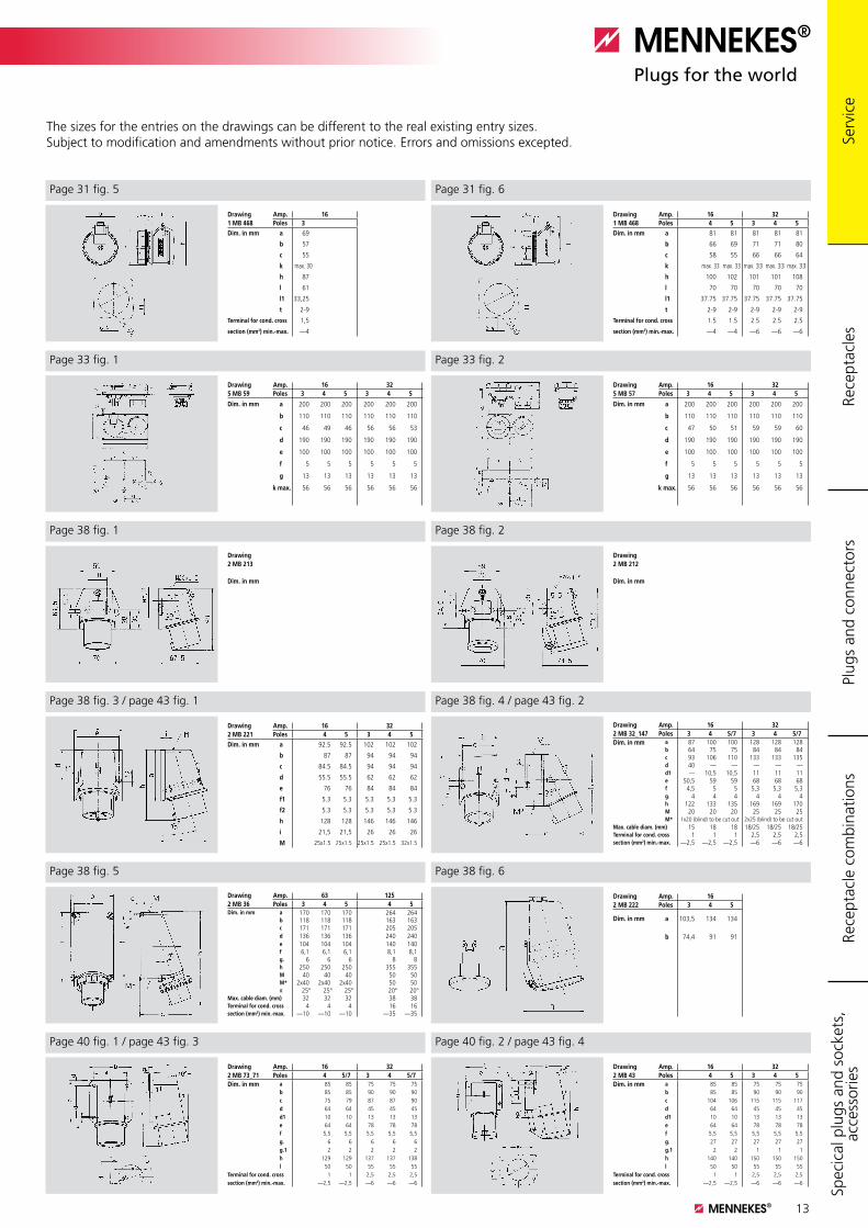
Drawings and dimensions
The sizes for the entries on the drawings can be different to the real existing entry sizes. Subject to modification and amendments without prior notice. Errors and omissions excepted.
Page 38 fig. 2
Page 38 fig. 4 / page 43 fig. 2
Page 38 fig. 6
Page 40 fig. 2 / page 43 fig. 4
Page 31 fig. 6 Page 31 fig. 5
Page 38 fig. 1
Page 38 fig. 3 / page 43 fig. 1
Page 38 fig. 5
Page 40 fig. 1 / page 43 fig. 3
Page 33 fig. 1 Page 33 fig. 2
Drawing Amp. 161 MB 468 Poles 3Dim. in mm a 69
b 57
c 55
k max. 30
h 87
l 61
l1 33,25
t 2-9
Terminal for cond. cross 1,5
section (mm2) min.-max. —4
Drawing Amp. 16 321 MB 468 Poles 4 5 3 4 5Dim. in mm a 81 81 81 81 81
b 66 69 71 71 80
c 58 55 66 66 64
k max. 33 max. 33 max. 33 max. 33 max. 33
h 100 102 101 101 108
l 70 70 70 70 70
l1 37.75 37.75 37.75 37.75 37.75
t 2-9 2-9 2-9 2-9 2-9
Terminal for cond. cross 1.5 1.5 2.5 2.5 2.5
section (mm2) min.-max. —4 —4 —6 —6 —6
Drawing Amp. 16 325 MB 59 Poles 3 4 5 3 4 5
Dim. in mm a 200 200 200 200 200 200
b 110 110 110 110 110 110
c 46 49 46 56 56 53
d 190 190 190 190 190 190
e 100 100 100 100 100 100
f 5 5 5 5 5 5
g 13 13 13 13 13 13
k max. 56 56 56 56 56 56
Drawing Amp. 16 325 MB 57 Poles 3 4 5 3 4 5
Dim. in mm a 200 200 200 200 200 200
b 110 110 110 110 110 110
c 47 50 51 59 59 60
d 190 190 190 190 190 190
e 100 100 100 100 100 100
f 5 5 5 5 5 5
g 13 13 13 13 13 13
k max. 56 56 56 56 56 56
Drawing2 MB 213
Dim. in mm
Drawing2 MB 212
Dim. in mm
Drawing Amp. 16 322 MB 221 Poles 4 5 3 4 5Dim. in mm a 92.5 92.5 102 102 102
b 87 87 94 94 94
c 84.5 84.5 94 94 94
d 55.5 55.5 62 62 62
e 76 76 84 84 84
f1 5.3 5.3 5.3 5.3 5.3
f2 5.3 5.3 5.3 5.3 5.3
h 128 128 146 146 146
i 21,5 21,5 26 26 26
M 25x1.5 25x1.5 25x1.5 25x1.5 32x1.5
Drawing Amp. 16 322 MB 32_147 Poles 3 4 5/7 3 4 5/7Dim. in mm a 87 100 100 128 128 128
b 64 75 75 84 84 84c 93 106 110 133 133 135d 40 — — — — —d1 — 10,5 10,5 11 11 11e 50,5 59 59 68 68 68f 4,5 5 5 5,3 5,3 5,3g. 4 4 4 4 4 4h 122 133 135 169 169 170M 20 20 20 25 25 25M* 1x20 (blind) to be cut out 2x25 (blind) to be cut out
Max. cable diam. (mm) 15 18 18 18/25 18/25 18/25Terminal for cond. cross 1 1 1 2,5 2,5 2,5section (mm2) min.-max. —2,5 —2,5 —2,5 —6 —6 —6
Drawing Amp. 63 1252 MB 36 Poles 3 4 5 4 5Dim. in mm a 170 170 170 264 264
b 118 118 118 163 163c 171 171 171 205 205d 136 136 136 240 240e 104 104 104 140 140f 6,1 6,1 6,1 8,1 8,1g. 6 6 6 8 8h 250 250 250 355 355M 40 40 40 50 50M* 2x40 2x40 2x40 50 50α 25° 25° 25° 20° 20°
Max. cable diam. (mm) 32 32 32 38 38Terminal for cond. cross 4 4 4 16 16section (mm2) min.-max. —10 —10 —10 —35 —35
Drawing Amp. 162 MB 222 Poles 3 4 5
Dim. in mm a 103,5 134 134
b 74,4 91 91
Drawing Amp. 16 322 MB 73_71 Poles 4 5/7 3 4 5/7Dim. in mm a 85 85 75 75 75
b 85 85 90 90 90c 75 79 87 87 90d 64 64 45 45 45d1 10 10 13 13 13e 64 64 78 78 78f 5,5 5,5 5,5 5,5 5,5g. 6 6 6 6 6g.1 2 2 2 2 2h 129 129 137 137 138l 50 50 55 55 55
Terminal for cond. cross 1 1 2,5 2,5 2,5section (mm2) min.-max. —2,5 —2,5 —6 —6 —6
Drawing Amp. 16 322 MB 43 Poles 4 5 3 4 5Dim. in mm a 85 85 75 75 75
b 85 85 90 90 90c 104 106 115 115 117d 64 64 45 45 45d1 10 10 13 13 13e 64 64 78 78 78f 5,5 5,5 5,5 5,5 5,5g. 27 27 27 27 27g.1 2 2 1 1 1h 140 140 150 150 150l 50 50 55 55 55
Terminal for cond. cross 1 1 2,5 2,5 2,5section (mm2) min.-max. —2,5 —2,5 —6 —6 —6
Rece
ptac
les
Plug
s an
d co
nnec
tors
Rece
ptac
le c
ombi
natio
nsSp
ecic
al p
lugs
and
soc
kets
, ac
cess
orie
s Se
rvic
e
14
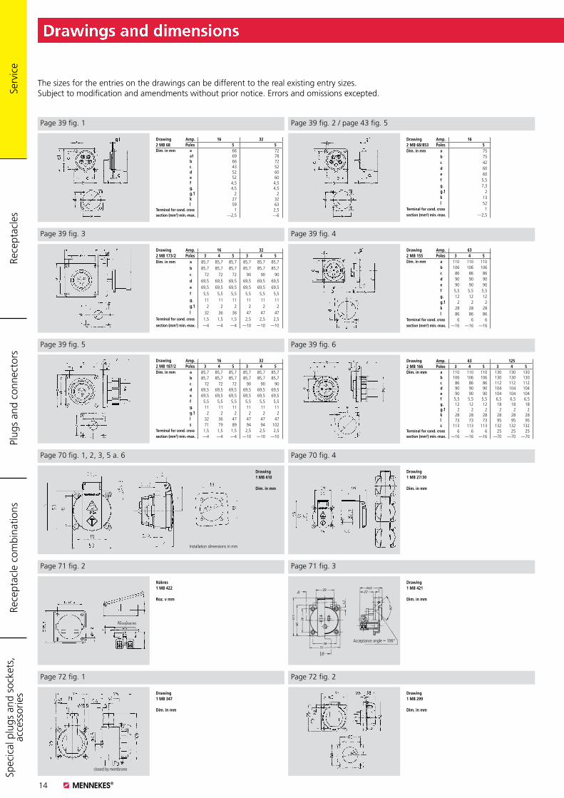
Drawings and dimensions
The sizes for the entries on the drawings can be different to the real existing entry sizes. Subject to modification and amendments without prior notice. Errors and omissions excepted.
Page 39 fig. 2 / page 43 fig. 5Page 39 fig. 1
Page 39 fig. 3 Page 39 fig. 4
Page 39 fig. 6
Page 70 fig. 4Page 70 fig. 1, 2, 3, 5 a. 6
Page 72 fig. 1
Page 39 fig. 5
Drawing Amp. 162 MB 68/853 Poles 5Dim. in mm a 75
b 75c 42d 60e 60f 5,5g. 7,3g.1 2k 13l 52
Terminal for cond. cross 1section (mm2) min.-max. —2,5
Drawing Amp. 16 322 MB 173/2 Poles 3 4 5 3 4 5Dim. in mm a 85,7 85,7 85,7 85,7 85,7 85,7
b 85,7 85,7 85,7 85,7 85,7 85,7c 72 72 72 90 90 90d 69,5 69,5 69,5 69,5 69,5 69,5e 69,5 69,5 69,5 69,5 69,5 69,5f 5,5 5,5 5,5 5,5 5,5 5,5g. 11 11 11 11 11 11g.1 2 2 2 2 2 2l 32 36 36 47 47 47
Terminal for cond. cross 1,5 1,5 1,5 2,5 2,5 2,5section (mm2) min.-max. —4 —4 —4 —10 —10 —10
Drawing Amp. 632 MB 155 Poles 3 4 5Dim. in mm a 110 110 110
b 106 106 106c 86 86 86d 90 90 90e 90 90 90f 5,5 5,5 5,5g. 12 12 12g.1 2 2 2k 28 28 28l 86 86 86
Terminal for cond. cross 6 6 6section (mm2) min.-max. —16 —16 —16
Drawing Amp. 16 322 MB 187/2 Poles 3 4 5 3 4 5Dim. in mm a 85,7 85,7 85,7 85,7 85,7 85,7
b 85,7 85,7 85,7 85,7 85,7 85,7c 72 72 72 90 90 90d 69,5 69,5 69,5 69,5 69,5 69,5e 69,5 69,5 69,5 69,5 69,5 69,5f 5,5 5,5 5,5 5,5 5,5 5,5g. 11 11 11 11 11 11g.1 2 2 2 2 2 2l 32 36 47 47 47 47s 71 79 89 94 94 102
Terminal for cond. cross 1,5 1,5 1,5 2,5 2,5 2,5section (mm2) min.-max. —4 —4 —4 —10 —10 —10
Drawing Amp. 63 1252 MB 166 Poles 3 4 5 3 4 5Dim. in mm a 110 110 110 130 130 130
b 106 106 106 130 130 130c 86 86 86 112 112 112d 90 90 90 104 104 104e 90 90 90 104 104 104f 5,5 5,5 5,5 6,5 6,5 6,5g. 12 12 12 18 18 18g.1 2 2 2 2 2 2k 28 28 28 28 28 28l 73 73 73 95 95 95s 113 113 113 132 132 132
Terminal for cond. cross 6 6 6 25 25 25section (mm2) min.-max. —16 —16 —16 —70 —70 —70
Drawing1 MB 410
Dim. in mm
Installation dimensions in mm
Drawing1 MB 27/30
Dim. in mm
Page 71 fig. 3
Acceptance angle ~ 106°
Drawing1 MB 421
Dim. in mm
closed by membrane
Drawing1 MB 347
Dim. in mm
Page 72 fig. 2
Drawing1 MB 299
Dim. in mm
Page 71 fig. 2
Nákres1 MB 422
Roz. v mm
Receptacles
Drawing Amp. 16 322 MB 68 Poles 5 5Dim. in mm a 66 72
a1 69 78b 66 72c 43 52d 52 60e 52 60f 4,5 4,5g. 4,5 4,5g.1 2 2k 27 32l 59 63
Terminal for cond. cross 1 2,5section (mm2) min.-max. —2,5 —6
Rece
ptac
les
Plug
s an
d co
nnec
tors
Rece
ptac
le c
ombi
natio
nsSp
ecic
al p
lugs
and
soc
kets
, ac
cess
orie
s Se
rvic
e
15
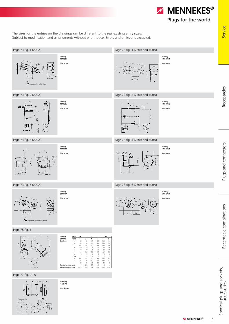
Drawings and dimensions
The sizes for the entries on the drawings can be different to the real existing entry sizes. Subject to modification and amendments without prior notice. Errors and omissions excepted.
Page 73 fig. 1 (250A and 400A)
Page 73 fig. 2 (200A) Page 73 fig. 2 (250A and 400A)
Page 73 fig. 3 (250A and 400A)
Page 73 fig. 6 (250A and 400A)Page 73 fig. 6 (200A)
Page 75 fig. 1
Page 73 fig. 3 (200A)
Page 73 fig. 1 (200A)
separate pilot cable gland
Drawing1 MB 385
Dim. in mm
Drawing1 MB 389/1
Dim. in mm
Drawing 1 MB 386
Dim. in mm
Drawing 1 MB 403/2
Dim. in mm
Drawing1 MB 384
Dim. in mm
Drawing1 MB 388/1
Dim. in mm
separate pilot cable gland
Drawing2 MB 197
Dim. in mm
Drawing2 MB 200/1
Dim. in mm
Drawing Amp. 16 32 632 MB 40 Poles 5 3 4 5 4 5Dim. in mm a 85 85 85 85 114 114
b 85 85 85 85 114 114c 141 141 141 144 180 180d 70 70 70 70 90 90e 70 70 70 70 90 90f 6,2 6,2 6,2 6,2 6,2 6,2g. 6 6 6 6 6 6g.1 2 2 2 2 2 2h 181 181 181 188 242 242s 86 93 93 100 113 113l 30 30 30 30 40 40
Terminal for cond. cross 1 2,5 2,5 2,5 4 4section (mm2) min.-max. —2,5 —6 —6 —6 —10 —10
Rece
ptac
les
Plug
s an
d co
nnec
tors
Rece
ptac
le c
ombi
natio
nsSp
ecic
al p
lugs
and
soc
kets
, ac
cess
orie
s Se
rvic
e
Page 77 fig. 2 - 5
Fixing details
Drawing1 MB 305
Dim. in mm
16
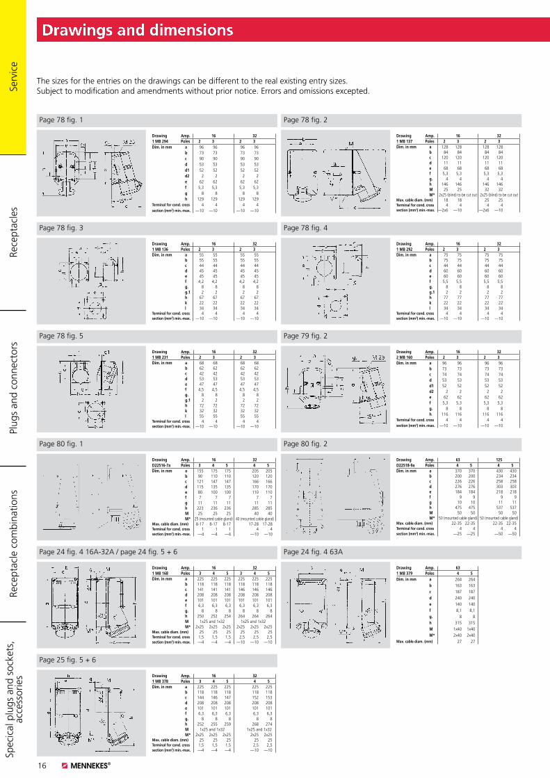
Drawings and dimensions
The sizes for the entries on the drawings can be different to the real existing entry sizes. Subject to modification and amendments without prior notice. Errors and omissions excepted.
Page 78 fig. 2
Page 78 fig. 3 Page 78 fig. 4
Page 79 fig. 2Page 78 fig. 5
Drawing Amp. 16 321 MB 137 Poles 2 3 2 3Dim. in mm a 128 128 128 128
b 84 84 84 84c 120 120 120 120d 11 11 11 11e 68 68 68 68f 5,3 5,3 5,3 5,3g. 4 4 4 4h 146 146 146 146M 25 25 32 32M* 2x25 (blind) to be cut out 2x25 (blind) to be cut out
Max. cable diam. (mm) 18 18 25 25Terminal for cond. cross 4 4 4 4section (mm2) min.-max. —2x6 —10 —2x6 —10
Drawing Amp. 16 321 MB 136 Poles 2 3 2 3Dim. in mm a 55 55 55 55
b 55 55 55 55c 44 44 44 44d 45 45 45 45e 45 45 45 45f 4,2 4,2 4,2 4,2g. 8 8 8 8g.1 2 2 2 2h 67 67 67 67k 22 22 22 22l 34 34 34 34
Terminal for cond. cross 4 4 4 4section (mm2) min.-max. —10 —10 —10 —10
Drawing Amp. 16 321 MB 292 Poles 2 3 2 3Dim. in mm a 75 75 75 75
b 75 75 75 75c 44 44 44 44d 60 60 60 60e 60 60 60 60f 5,5 5,5 5,5 5,5g. 8 8 8 8g.1 2 2 2 2h 77 77 77 77k 22 22 22 22l 34 34 34 34
Terminal for cond. cross 4 4 4 4section (mm2) min.-max. —10 —10 —10 —10
Drawing Amp. 16 321 MB 231 Poles 2 3 2 3Dim. in mm a 68 68 68 68
b 62 62 62 62c 42 42 42 42d 53 53 53 53e 47 47 47 47f 4,5 4,5 4,5 4,5g. 8 8 8 8g.1 2 2 2 2h 72 72 72 72k 32 32 32 32l 55 55 55 55
Terminal for cond. cross 4 4 4 4section (mm2) min.-max. —10 —10 —10 —10
Drawing Amp. 16 322 MB 160 Poles 2 3 2 3Dim. in mm a 96 96 96 96
b 73 73 73 73c 74 74 74 74d 53 53 53 53d1 52 52 52 52d2 2 2 2 2e 62 62 62 62f 5,3 5,3 5,3 5,3g. 8 8 8 8h 116 116 116 116
Terminal for cond. cross 4 4 4 4section (mm2) min.-max. —10 —10 —10 —10
Page 78 fig. 1
Drawing Amp. 16 321 MB 294 Poles 2 3 2 3Dim. in mm a 96 96 96 96
b 73 73 73 73c 90 90 90 90d 53 53 53 53d1 52 52 52 52d2 2 2 2 2e 62 62 62 62f 5,3 5,3 5,3 5,3g 8 8 8 8h 129 129 129 129
Terminal for cond. cross 4 4 4 4section (mm2) min.-max. —10 —10 —10 —10
Rece
ptac
les
Plug
s an
d co
nnec
tors
Rece
ptac
le c
ombi
natio
nsSp
ecic
al p
lugs
and
soc
kets
, ac
cess
orie
s Se
rvic
e
Page 80 fig. 2Page 80 fig. 1
Drawing Amp. 16 32D22516-7a Poles 3 4 5 4 5Dim. in mm a 155 175 175 205 205
b 90 110 110 120 120c 121 147 147 166 166d 115 135 135 170 170e 80 100 100 110 110f 7 7 7 7 7g 11 11 11 11 11h 223 236 236 285 285M 25 25 25 40 40M* 25 (mounted cable gland) 40 (mounted cable gland)
Max. cable diam. (mm) 8-17 8-17 8-17 17-28 17-28Terminal for cond. cross 1 1 1 4 4section (mm2) min.-max. —4 —4 —4 —10 —10
Drawing Amp. 63 125D22518-9a Poles 4 5 4 5Dim. in mm a 370 370 430 430
b 200 200 234 234c 226 226 258 258d 276 276 303 303e 184 184 218 218f 9 9 9 9g 10 10 11 11h 475 475 537 537M 50 50 50 50M* 50 (mounted cable gland) 50 (mounted cable gland)
Max. cable diam. (mm) 22-35 22-35 22-35 22-35Terminal for cond. cross 4 4 4 4section (mm2) min.-max. —25 —25 —50 —50
Page 24 fig. 4 63APage 24 fig. 4 16A-32A / page 24 fig. 5 + 6
Drawing Amp. 16 321 MB 168 Poles 3 4 5 3 4 5Dim. in mm a 225 225 225 225 225 225
b 118 118 118 118 118 118c 141 141 141 146 146 146d 208 208 208 208 208 208e 101 101 101 101 101 101f 6,3 6,3 6,3 6,3 6,3 6,3g. 8 8 8 8 8 8h 250 252 254 264 264 264M 1x25 and 1x32 1x25 and 1x32M* 2x25 2x25 2x25 2x25 2x25 2x25
Max. cable diam. (mm) 25 25 25 25 25 25Terminal for cond. cross 1,5 1,5 1,5 2,5 2,5 2,5section (mm2) min.-max. —4 —4 —4 —10 —10 —10
Drawing Amp. 631 MB 379 Poles 4 5Dim. in mm a 264 264
b 163 163c 187 187d 240 240e 140 140f 8,1 8,1g. 8 8h 315 315M 1x40 1x40M* 2x40 2x40
Max. cable diam. (mm) 27 27
Page 25 fig. 5 + 6
Drawing Amp. 16 321 MB 378 Poles 3 4 5 4 5Dim. in mm a 225 225 225 225 225
b 118 118 118 118 118c 144 146 147 152 153d 208 208 208 208 208e 101 101 101 101 101f 6,3 6,3 6,3 6,3 6,3g. 8 8 8 8 8h 252 255 259 268 274M 1x25 and 1x32 1x25 and 1x32 M* 2x25 2x25 2x25 2x25 2x25
Max. cable diam. (mm) 25 25 25 25 25Terminal for cond. cross 1,5 1,5 1,5 2,5 2,5section (mm2) min.-max. —4 —4 —4 —10 —10
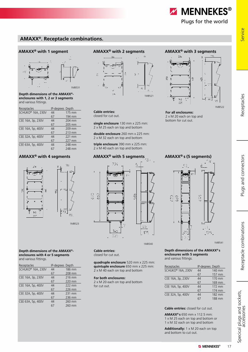
17
Drawings and dimensions
Cable entries: closed for cut out.
single enclosure 130 mm x 225 mm: 2 x M 25 each on top and bottom
double enclosure 260 mm x 225 mm: 2 x M 32 each on top and bottom
triple enclosure 390 mm x 225 mm: 2 x M 40 each on top and bottom
For all enclosures: 2 x M 20 each on top andbottom for cut out.
AMAXX® with 1 segment AMAXX® with 2 segments AMAXX® with 3 segments
Depth dimensions of the AMAXX®- enclosures with 1, 2 or 3 segments and various fittings.
Receptacles IP-degrees DepthSCHUKO® 16A, 230V 44 175 mm 67 194 mmCEE 16A, 3p, 230V 44 204 mm 67 205 mmCEE 16A, 5p, 400V 44 209 mm 67 213 mmCEE 32A, 5p, 400V 44 221 mm 67 227 mmCEE 63A, 5p, 400V 44 248 mm 67 248 mm
AMAXX® with 4 segments AMAXX® with 5 segments AMAXX® s (5 segments)
Cable entries: closed for cut out.
quadruple enclosure 520 mm x 225 mm: quintuple enclosure 650 mm x 225 mm: 2 x M 40 each on top and bottom
For both enclosures: 2 x M 20 each on top and bottom for cut out.
Depth dimensions of the AMAXX®- enclosures with 4 or 5 segments and various fittings.
Receptacles IP-degrees DepthSCHUKO® 16A, 230V 44 186 mm 67 208 mmCEE 16A, 3p, 230V 44 216 mm 67 220 mmCEE 16A, 5p, 400V 44 222 mm 67 226 mmCEE 32A, 5p, 400V 44 231 mm 67 236 mmCEE 63A, 5p, 400V 44 260 mm 67 260 mm
Depth dimensions of the AMAXX® s enclosures with 5 segments and various fittings. Receptacles IP-degrees DepthSCHUKO® 16A, 230V 44 140 mm 67 157 mmCEE 16A, 3p, 230V 44 170 mm 67 169 mmCEE 16A, 5p, 400V 44 172 mm 67 174 mmCEE 32A, 5p, 400V 44 182 mm 67 188 mm
Cable entries: closed for cut out. AMAXX® s 650 mm x 112.5 mm: 1 x M 25 each on top and bottom or1 x M 32 each on top and bottom Additionally: 1 x M 20 each on top and bottom to cut out.
1MB531
1MB521
1MB522
1MB5411MB540
1MB523
AMAXX®. Receptacle combinations.
Rece
ptac
les
Plug
s an
d co
nnec
tors
Rece
ptac
le c
ombi
natio
nsSp
ecic
al p
lugs
and
soc
kets
, ac
cess
orie
s Se
rvic
e
18
Drawings and dimensions
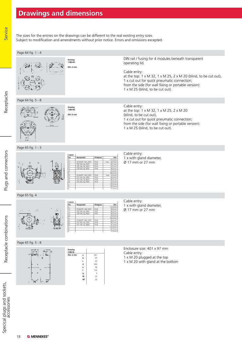
Drawing1 MB 441
Dim. in mm
DIN rail / fusing for 4 modules beneath transparentoperating lid.
Cable entry: at the top: 1 x M 32, 1 x M 25, 2 x M 20 (blind, to be cut out), 1 x cut out for quick pneumatic connection; from the side (for wall fixing or portable version):1 x M 25 (blind, to be cut out).
Drawing1 MB 442
Dim. in mm
Cable entry:at the top: 1 x M 32, 1 x M 25, 2 x M 20 (blind, to be cut out), 1 x cut out for quick pneumatic connection;from the side (for wall fixing or portable version):1 x M 25 (blind, to be cut out).
Cable entry:1 x with gland diameter, Ø 17 mm or 27 mm
Drawing 5 MB 35Dim. in mm a 401
b 97
c 63
d 364
e 56
f 5.5
g. 4
M 25
M* 25
Cable entry:1 x with gland diameter,Ø 17 mm or 27 mm
Enclosure size: 401 x 97 mmCable entry:1 x M 20 plugged at the top1 x M 20 with gland at the bottom
The sizes for the entries on the drawings can be different to the real existing entry sizes. Subject to modification and amendments without prior notice. Errors and omissions excepted.
Page 64 fig. 1 - 4
Page 64 fig. 5 - 8
Page 65 fig. 1 - 3
Page 65 fig. 4
Page 65 fig. 5 - 8
Rece
ptac
les
Plug
s an
d co
nnec
tors
Rece
ptac
le c
ombi
natio
nsSp
ecic
al p
lugs
and
soc
kets
, ac
cess
orie
s
3 MB 44
Pos. Receptacles IP-degrees Dim.a 114.0 mma1 SCHUKO®, 16A, 230V IP 44 max. 30.0 mma1 CEE 16A, 3p, 230V IP 44 52.7 mma1 CEE 16A, 5p, 400V IP 44 50.5 mma1 CEE 32A, 5p, 400V IP 44 64.0 mma2 30.0 mmb 160.0 mmb1 SCHUKO®, 16A, 230V IP 44 max. 18.0 mmb1 CEE 16A, 3p, 230V IP 44 42.0 mmb1 CEE 16A, 5p, 400V IP 44 40.0 mmb1 CEE 32A, 5p, 400V IP 44 53.2 mmc 133.0 mmd 97.0 mmy 17.0 mm
3 MB 45
Pos. Receptacles IP-degrees Dim.a 114.0 mma1 SCHUKO®, 16A, 230V IP 68 35.0 mma1 CEE 16A, 3p, 230V IP 67 56.3 mma1 CEE 16A, 5p, 400V IP 67 59.0 mma2 30.0 mmb 160.0 mmb1 SCHUKO®, 16A, 230V IP 44 24.0 mmb1 CEE 16A, 3p, 230V IP 44 44.3 mmb1 CEE 16A, 5p, 400V IP 44 47.0 mmc 133.0 mmd 97.0 mmy 17.0 mm
Serv
ice
19
Drawings and dimensions
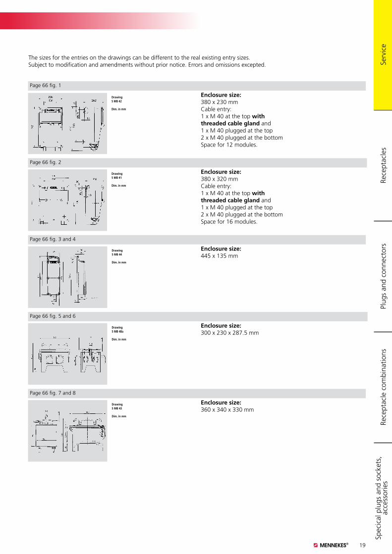
Drawing5 MB 42
Dim. in mm
Enclosure size: 380 x 230 mmCable entry:1 x M 40 at the top with threaded cable gland and1 x M 40 plugged at the top2 x M 40 plugged at the bottomSpace for 12 modules.
Drawing5 MB 41
Dim. in mm
Enclosure size: 380 x 320 mmCable entry:1 x M 40 at the top with threaded cable gland and1 x M 40 plugged at the top2 x M 40 plugged at the bottomSpace for 16 modules.
Drawing5 MB 44
Dim. in mm
Enclosure size:445 x 135 mm
Drawing5 MB 48a
Dim. in mm
Enclosure size:300 x 230 x 287.5 mm
Drawing5 MB 43
Dim. in mm
Enclosure size:360 x 340 x 330 mm
The sizes for the entries on the drawings can be different to the real existing entry sizes. Subject to modification and amendments without prior notice. Errors and omissions excepted.
Page 66 fig. 1
Page 66 fig. 2
Page 66 fig. 3 and 4
Page 66 fig. 5 and 6
Page 66 fig. 7 and 8
Rece
ptac
les
Plug
s an
d co
nnec
tors
Rece
ptac
le c
ombi
natio
nsSp
ecic
al p
lugs
and
soc
kets
, ac
cess
orie
s Se
rvic
e
20
Product information
Screwless:
Certified. Tested. Patented.
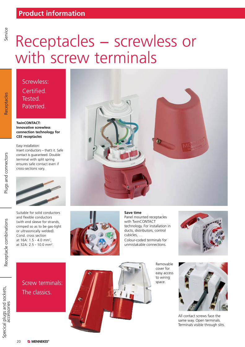
Receptacles − screwless or with screw terminals
TwinCONTACT: Innovative screwless connection technology for CEE receptacles
Easy installation: Insert conductors – that’s it. Safe contact is guaranteed. Double terminal with split spring ensures safe contact even if cross-sections vary.
Colour-coded terminals for unmistakable connections.
Save timePanel mounted receptacles with TwinCONTACT technology. For installation in ducts, distributors, control cubicles, …
Removable cover for easy access to wiring space.
All contact screws face the same way. Open terminals. Terminals visible through slits.
Suitable for solid conductors and flexible conductors (with end sleeve for strands, crimped so as to be gas-tight or ultrasonically welded).Cond. cross sectionat 16A: 1.5 - 4.0 mm2,at 32A: 2.5 - 10.0 mm2.
Rece
ptac
les
Plug
s an
d co
nnec
tors
Rece
ptac
le c
ombi
natio
nsSp
ecic
al p
lugs
and
soc
kets
, ac
cess
orie
s Se
rvic
e
Screw terminals:
The classics.

21
Product information
AMELAN is resistant to:
K sea waterK detergentsK trichlorethyleneK tolueneK edible fatK aqueous soap solutionK caustic sodaK motor oilsK milkK caustic potashK washing up liquidK fruit juicesK diesel oilK gasolineK aqueous ammonia solution
Fortoughest conditions.
AMELAN
Resistance to chemicals
AMELAN is the plastic for plugs and sockets where certain chemicals or other corrosive substances are used. AMELAN has excellent resistance to fuels, oils and fats, dilute acids and alkalines, cleaning fluids, most aqueous salt solutions and a wide variety of chemicals including aliphatic hydrocarbons.
AMELAN plastic material (PBT) combines outstanding mechanical, thermal and electrical properties with excellent dimensional stability and resistance to chemicals. It is fit for action in chemical plants, in refineries, in the food processing industry, in wash-down areas and so on.
Rece
ptac
les
Plug
s an
d co
nnec
tors
Rece
ptac
le c
ombi
natio
nsSp
ecic
al p
lugs
and
soc
kets
, ac
cess
orie
s Se
rvic
e
22
Am
per
e
Pole
s
110V50 a. 60 Hz
230V50 a. 60 Hz
400V50 a. 60 Hz
500V50 a. 60 Hz
>50 - 500V
100 - 300 Hz
>50 - 500V>300 - 500 Hz
3p 4p 5p 3p 4p 5p 3p 4p 5p 3p 4p 5p 3p 4p 5p 3p 4p 5p
4h 4h 4h 6h 9h 9h 9h 6h 6h 7h 7h 7h 10h 10h 10h 2h 2h 2h
Part numbersImage Title / description
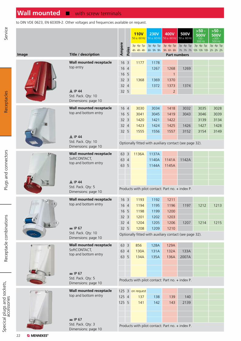
to DIN VDE 0623, EN 60309-2. Other voltages and frequencies available on request.
Wall mounted K with screw terminals
Wall mounted receptacletop entry
IP 44Std. Pack. Qty: 10Dimensions: page 10
Wall mounted receptacletop and bottom entry
IP 44Std. Pack. Qty: 10Dimensions: page 10
Wall mounted receptacleSoftCONTACT, top and bottom entry
IP 44Std. Pack. Qty: 5Dimensions: page 10
Wall mounted receptacletop and bottom entry
IP 67Std. Pack. Qty: 10Dimensions: page 10
Wall mounted receptacleSoftCONTACT, top and bottom entry
IP 67Std. Pack. Qty: 5Dimensions: page 10
Wall mounted receptacletop and bottom entry
IP 67Std. Pack. Qty: 3Dimensions: page 10
16 3 1177 1178
16 4 1267 1268 1269
16 5 1
32 3 1368 1369 1370
32 4 1372 1373 1374
32 5 2
16 4 3030 3034 1418 3032 3035 3028
16 5 3041 3045 1419 3043 3046 3039
32 3 1420 1421 1422 3139 3134
32 4 1423 1424 1425 1426 1427 1428
32 5 1555 1556 1557 3152 3154 3149
Optionally fitted with auxiliary contact (see page 32).
63 3 1136A 1137A
63 4 1140A 1141A 1142A
63 5 1144A 1145A
Products with pilot contact: Part no. + index P.
16 3 1193 1192 1211
16 4 1194 1195 1196 1197 1212 1213
16 5 1198 1199 1200
32 3 1201 1202 1203
32 4 1204 1205 1206 1207 1214 1215
32 5 1208 1209 1210
Optionally fitted with auxiliary contact (see page 32).
63 3 856 128A 129A
63 4 130A 131A 132A 133A
63 5 134A 135A 136A 2007A
Products with pilot contact: Part no. + index P.
125 3 on request
125 4 137 138 139 140
125 5 141 142 143 2139
Products with pilot contact: Part no. + index P.
Rece
ptac
les
Plug
s an
d co
nnec
tors
Rece
ptac
le c
ombi
natio
nsSp
ecic
al p
lugs
and
soc
kets
, ac
cess
orie
s Se
rvic
e
23
Image Title / description
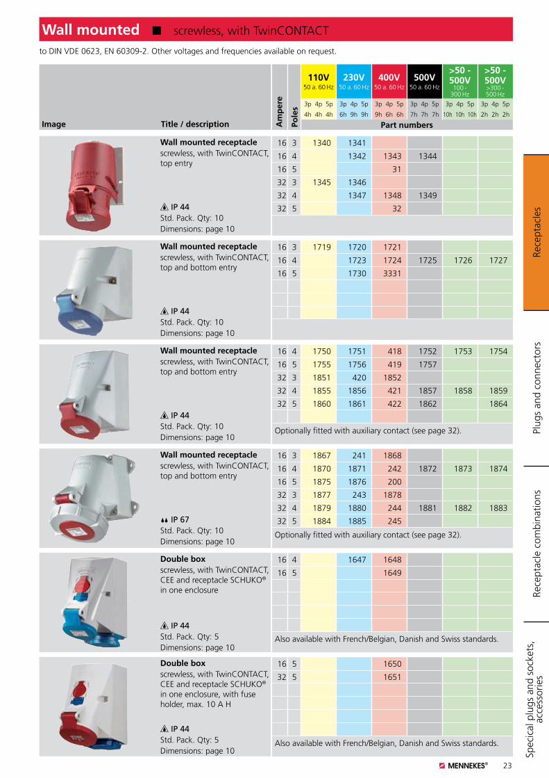
to DIN VDE 0623, EN 60309-2. Other voltages and frequencies available on request.
Wall mounted K screwless, with TwinCONTACT
Wall mounted receptaclescrewless, with TwinCONTACT, top entry
IP 44Std. Pack. Qty: 10Dimensions: page 10
Wall mounted receptaclescrewless, with TwinCONTACT, top and bottom entry
IP 44Std. Pack. Qty: 10Dimensions: page 10
Wall mounted receptaclescrewless, with TwinCONTACT, top and bottom entry
IP 44Std. Pack. Qty: 10Dimensions: page 10
Wall mounted receptaclescrewless, with TwinCONTACT, top and bottom entry
IP 67Std. Pack. Qty: 10Dimensions: page 10
Double boxscrewless, with TwinCONTACT, CEE and receptacle SCHUKO® in one enclosure
IP 44Std. Pack. Qty: 5Dimensions: page 10
Double boxscrewless, with TwinCONTACT, CEE and receptacle SCHUKO® in one enclosure, with fuse holder, max. 10 A H
IP 44Std. Pack. Qty: 5Dimensions: page 10
16 3 1340 1341
16 4 1342 1343 1344
16 5 31
32 3 1345 1346
32 4 1347 1348 1349
32 5 32
16 3 1719 1720 1721
16 4 1723 1724 1725 1726 1727
16 5 1730 3331
16 4 1750 1751 418 1752 1753 1754
16 5 1755 1756 419 1757
32 3 1851 420 1852
32 4 1855 1856 421 1857 1858 1859
32 5 1860 1861 422 1862 1864
Optionally fitted with auxiliary contact (see page 32).
16 3 1867 241 1868
16 4 1870 1871 242 1872 1873 1874
16 5 1875 1876 200
32 3 1877 243 1878
32 4 1879 1880 244 1881 1882 1883
32 5 1884 1885 245
Optionally fitted with auxiliary contact (see page 32).
16 4 1647 1648
16 5 1649
Also available with French/Belgian, Danish and Swiss standards.
16 5 1650
32 5 1651
Also available with French/Belgian, Danish and Swiss standards.
Rece
ptac
les
Plug
s an
d co
nnec
tors
Rece
ptac
le c
ombi
natio
nsSp
ecic
al p
lugs
and
soc
kets
, ac
cess
orie
s
Am
per
e
Pole
s
110V50 a. 60 Hz
230V50 a. 60 Hz
400V50 a. 60 Hz
500V50 a. 60 Hz
>50 - 500V
100 - 300 Hz
>50 - 500V>300 - 500 Hz
3p 4p 5p 3p 4p 5p 3p 4p 5p 3p 4p 5p 3p 4p 5p 3p 4p 5p
4h 4h 4h 6h 9h 9h 9h 6h 6h 7h 7h 7h 10h 10h 10h 2h 2h 2h
Part numbers
24
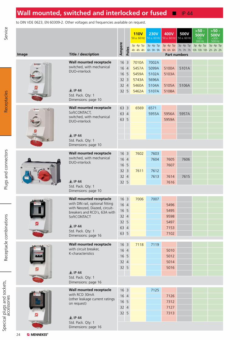
Image Title / description
Wall mounted receptacleswitched, with mechanical DUO-interlock
IP 44Std. Pack. Qty: 1 Dimensions: page 10
Wall mounted receptacleSoftCONTACT, switched, with mechanical DUO-interlock
IP 44Std. Pack. Qty: 1 Dimensions: page 10
Wall mounted receptacleswitched, with mechanical DUO-interlock
IP 44Std. Pack. Qty: 1 Dimensions: page 10
to DIN VDE 0623, EN 60309-2. Other voltages and frequencies available on request.
Wall mounted, switched and interlocked or fused K IP 44
16 3 7010A 7002A
16 4 5457A 5099A 5100A 5101A
16 5 5459A 5102A 5103A
32 3 5743A 5696A
32 4 5460A 5104A 5105A 5106A
32 5 5462A 5107A 5108A
63 3 6569 6571A
63 4 5955A 5956A 5957A
63 5 5959A
16 3 7602 7603
16 4 7604 7605 7606
16 5 7607
32 3 7611 7612
32 4 7613 7614 7615
32 5 7616
Rece
ptac
les
Plug
s an
d co
nnec
tors
Rece
ptac
le c
ombi
natio
nsSp
ecic
al p
lugs
and
soc
kets
, ac
cess
orie
s Se
rvic
e
Am
per
e
Pole
s
110V50 a. 60 Hz
230V50 a. 60 Hz
400V50 a. 60 Hz
500V50 a. 60 Hz
>50 - 500V
100 - 300 Hz
>50 - 500V>300 - 500 Hz
3p 4p 5p 3p 4p 5p 3p 4p 5p 3p 4p 5p 3p 4p 5p 3p 4p 5p
4h 4h 4h 6h 9h 9h 9h 6h 6h 7h 7h 7h 10h 10h 10h 2h 2h 2h
Part numbers
Wall mounted receptaclewith DIN rail, optional fitting with Neozed, Diazed, circuit-breakers and RCD´s, 63A with SoftCONTACT
IP 44Std. Pack. Qty: 1 Dimensions: page 16
Wall mounted receptaclewith circuit breaker, K-characteristics
IP 44Std. Pack. Qty: 1Dimensions: page 16
Wall mounted receptaclewith RCD 30mA (other leakage current ratings on request)
IP 44Std. Pack. Qty: 1 Dimensions: page 16
16 3 7006 7007
16 4 5496
16 5 5495
32 4 9598
32 5 5497
63 4 7153
63 5 7102
16 3 7118 7119
16 4 5010
16 5 5012
32 4 5014
32 5 5016
16 3 7125
16 4 7126
16 5 7312
32 4 7127
32 5 7313
25
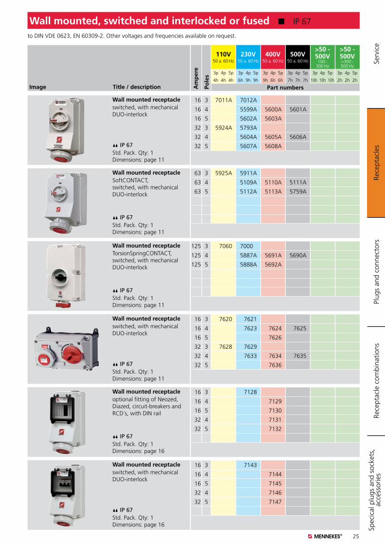
Image Title / description
Wall mounted receptacleswitched, with mechanical DUO-interlock
IP 67Std. Pack. Qty: 1 Dimensions: page 11
Wall mounted receptacleSoftCONTACT, switched, with mechanical DUO-interlock
IP 67Std. Pack. Qty: 1 Dimensions: page 11
Wall mounted receptacleTorsionSpringCONTACT, switched, with mechanical DUO-interlock
IP 67Std. Pack. Qty: 1 Dimensions: page 11
Wall mounted receptacleswitched, with mechanical DUO-interlock
IP 67Std. Pack. Qty: 1 Dimensions: page 11
to DIN VDE 0623, EN 60309-2. Other voltages and frequencies available on request.
16 3 7011A 7012A
16 4 5599A 5600A 5601A
16 5 5602A 5603A
32 3 5924A 5793A
32 4 5604A 5605A 5606A
32 5 5607A 5608A
63 3 5925A 5911A
63 4 5109A 5110A 5111A
63 5 5112A 5113A 5759A
125 3 7060 7000A
125 4 5887A 5691A 5690A
125 5 5888A 5692A
16 3 7620 7621
16 4 7623 7624 7625
16 5 7626
32 3 7628 7629
32 4 7633 7634 7635
32 5 7636
Wall mounted, switched and interlocked or fused K IP 67
Rece
ptac
les
Plug
s an
d co
nnec
tors
Rece
ptac
le c
ombi
natio
nsSp
ecic
al p
lugs
and
soc
kets
, ac
cess
orie
s
Am
per
e
Pole
s
110V50 a. 60 Hz
230V50 a. 60 Hz
400V50 a. 60 Hz
500V50 a. 60 Hz
>50 - 500V
100 - 300 Hz
>50 - 500V>300 - 500 Hz
3p 4p 5p 3p 4p 5p 3p 4p 5p 3p 4p 5p 3p 4p 5p 3p 4p 5p
4h 4h 4h 6h 9h 9h 9h 6h 6h 7h 7h 7h 10h 10h 10h 2h 2h 2h
Part numbers
Serv
ice
Wall mounted receptacleoptional fitting of Neozed, Diazed, circuit-breakers and RCD´s, with DIN rail
IP 67Std. Pack. Qty: 1 Dimensions: page 16
Wall mounted receptacleswitched, with mechanical DUO-interlock
IP 67Std. Pack. Qty: 1 Dimensions: page 16
16 3 7128
16 4 7129
16 5 7130
32 4 7131
32 5 7132
16 3 7143
16 4 7144
16 5 7145
32 4 7146
32 5 7147
26
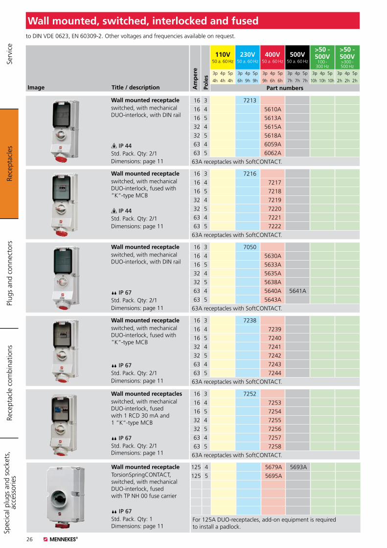
Image Title / description
Wall mounted receptacleswitched, with mechanical DUO-interlock, with DIN rail
IP 44Std. Pack. Qty: 2/1Dimensions: page 11
Wall mounted receptacleswitched, with mechanical DUO-interlock, fused with ”K“-type MCB
IP 44Std. Pack. Qty: 2/1Dimensions: page 11
Wall mounted receptacleswitched, with mechanical DUO-interlock, with DIN rail
IP 67Std. Pack. Qty: 2/1Dimensions: page 11
to DIN VDE 0623, EN 60309-2. Other voltages and frequencies available on request.
Wall mounted, switched, interlocked and fused
16 3 7213
16 4 5610A
16 5 5613A
32 4 5615A
32 5 5618A
63 4 6059A
63 5 6062A
63A receptacles with SoftCONTACT.
16 3 7216
16 4 7217
16 5 7218
32 4 7219
32 5 7220
63 4 7221
63 5 7222
63A receptacles with SoftCONTACT.
16 3 7050
16 4 5630A
16 5 5633A
32 4 5635A
32 5 5638A
63 4 5640A 5641A
63 5 5643A
63A receptacles with SoftCONTACT.
Wall mounted receptacleswitched, with mechanical DUO-interlock, fused with ”K“-type MCB
IP 67Std. Pack. Qty: 2/1Dimensions: page 11
16 3 7238
16 4 7239
16 5 7240
32 4 7241
32 5 7242
63 4 7243
63 5 7244
63A receptacles with SoftCONTACT.
Wall mounted receptaclesswitched, with mechanical DUO-interlock, fused with 1 RCD 30 mA and 1 ”K“-type MCB
IP 67Std. Pack. Qty: 2/1 Dimensions: page 11
16 3 7252
16 4 7253
16 5 7254
32 4 7255
32 5 7256
63 4 7257
63 5 7258
63A receptacles with SoftCONTACT.
Wall mounted receptacleTorsionSpringCONTACT, switched, with mechanical DUO-interlock, fused with TP NH 00 fuse carrier
IP 67Std. Pack. Qty: 1 Dimensions: page 11
125 4 5679A 5693A
125 5 5695A
For 125A DUO-receptacles, add-on equipment is required to install a padlock.
Rece
ptac
les
Plug
s an
d co
nnec
tors
Rece
ptac
le c
ombi
natio
nsSp
ecic
al p
lugs
and
soc
kets
, ac
cess
orie
s Se
rvic
e
Am
per
e
Pole
s
110V50 a. 60 Hz
230V50 a. 60 Hz
400V50 a. 60 Hz
500V50 a. 60 Hz
>50 - 500V
100 - 300 Hz
>50 - 500V>300 - 500 Hz
3p 4p 5p 3p 4p 5p 3p 4p 5p 3p 4p 5p 3p 4p 5p 3p 4p 5p
4h 4h 4h 6h 9h 9h 9h 6h 6h 7h 7h 7h 10h 10h 10h 2h 2h 2h
Part numbers
27
Image Title / description
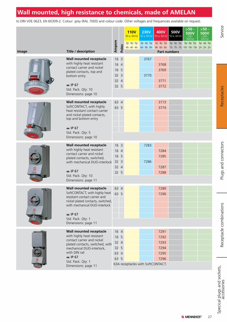
Wall mounted receptaclewith highly heat resistant contact carrier and nickel plated contacts, top and bottom entry
IP 67Std. Pack. Qty: 10Dimensions: page 10
Wall mounted receptacleSoftCONTACT, with highly heat resistant contact carrier and nickel plated contacts, top and bottom entry
IP 67Std. Pack. Qty: 5Dimensions: page 10
Wall mounted receptaclewith highly heat resistant contact carrier and nickel plated contacts, switched, with mechanical DUO-interlock
IP 67Std. Pack. Qty: 10Dimensions: page 11
Wall mounted receptacleSoftCONTACT, with highly heat resistant contact carrier and nickel plated contacts, switched, with mechanical DUO-interlock
IP 67Std. Pack. Qty: 1 Dimensions: page 11
to DIN VDE 0623, EN 60309-2. Colour: grey (RAL 7000) and colour code. Other voltages and frequencies available on request.
Wall mounted, high resistance to chemicals, made of AMELAN
Wall mounted receptaclewith highly heat resistant contact carrier and nickel plated contacts, switched, with mechanical DUO-interlock, with DIN rail IP 67Std. Pack. Qty: 1 Dimensions: page 11
16 3 3767
16 4 3768
16 5 3769
32 3 3770
32 4 3771
32 5 3772
63 4 3773
63 5 3774
16 3 7283
16 4 7284
16 5 7285
32 3 7286
32 4 7287
32 5 7288
63 4 7289
63 5 7290
16 4 7291
16 5 7292
32 4 7293
32 5 7294
63 4 7295
63 5 7296
63A receptacles with SoftCONTACT.
Rece
ptac
les
Plug
s an
d co
nnec
tors
Rece
ptac
le c
ombi
natio
nsSp
ecic
al p
lugs
and
soc
kets
, ac
cess
orie
s Se
rvic
e
Am
per
e
Pole
s
110V50 a. 60 Hz
230V50 a. 60 Hz
400V50 a. 60 Hz
500V50 a. 60 Hz
>50 - 500V
100 - 300 Hz
>50 - 500V>300 - 500 Hz
3p 4p 5p 3p 4p 5p 3p 4p 5p 3p 4p 5p 3p 4p 5p 3p 4p 5p
4h 4h 4h 6h 9h 9h 9h 6h 6h 7h 7h 7h 10h 10h 10h 2h 2h 2h
Part numbers
28
Image Title / description
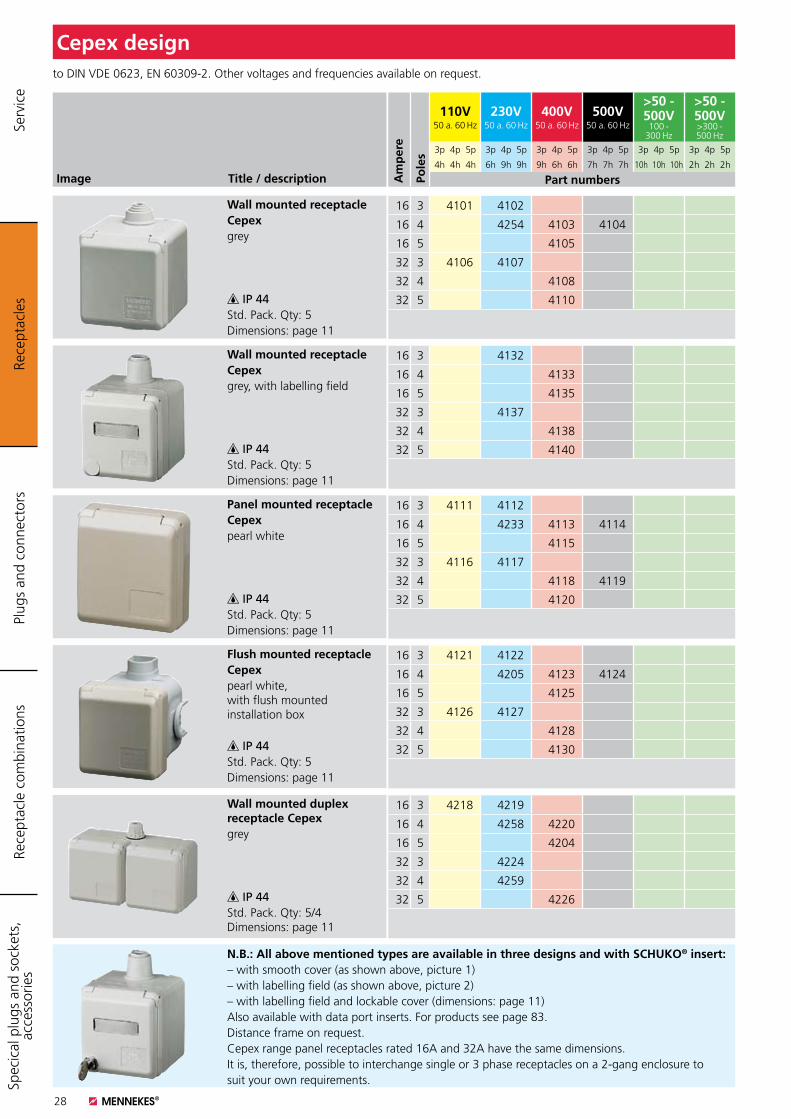
Wall mounted receptacleCepexgrey
IP 44Std. Pack. Qty: 5Dimensions: page 11
Wall mounted receptacleCepexgrey, with labelling field
IP 44Std. Pack. Qty: 5Dimensions: page 11
Panel mounted receptacleCepexpearl white
IP 44Std. Pack. Qty: 5Dimensions: page 11
Flush mounted receptacleCepexpearl white, with flush mounted installation box
IP 44Std. Pack. Qty: 5Dimensions: page 11
Wall mounted duplex receptacle Cepexgrey
IP 44Std. Pack. Qty: 5/4 Dimensions: page 11
to DIN VDE 0623, EN 60309-2. Other voltages and frequencies available on request.
16 3 4101 4102
16 4 4254 4103 4104
16 5 4105
32 3 4106 4107
32 4 4108
32 5 4110
16 3 4132
16 4 4133
16 5 4135
32 3 4137
32 4 4138
32 5 4140
16 3 4111 4112
16 4 4233 4113 4114
16 5 4115
32 3 4116 4117
32 4 4118 4119
32 5 4120
16 3 4121 4122
16 4 4205 4123 4124
16 5 4125
32 3 4126 4127
32 4 4128
32 5 4130
16 3 4218 4219
16 4 4258 4220
16 5 4204
32 3 4224
32 4 4259
32 5 4226
Cepex design
N.B.: All above mentioned types are available in three designs and with SCHUKO® insert:– with smooth cover (as shown above, picture 1)– with labelling field (as shown above, picture 2)– with labelling field and lockable cover (dimensions: page 11)Also available with data port inserts. For products see page 83.Distance frame on request.Cepex range panel receptacles rated 16A and 32A have the same dimensions. It is, therefore, possible to interchange single or 3 phase receptacles on a 2-gang enclosure to suit your own requirements.
Rece
ptac
les
Plug
s an
d co
nnec
tors
Rece
ptac
le c
ombi
natio
nsSp
ecic
al p
lugs
and
soc
kets
, ac
cess
orie
s Se
rvic
e
Am
per
e
Pole
s
110V50 a. 60 Hz
230V50 a. 60 Hz
400V50 a. 60 Hz
500V50 a. 60 Hz
>50 - 500V
100 - 300 Hz
>50 - 500V>300 - 500 Hz
3p 4p 5p 3p 4p 5p 3p 4p 5p 3p 4p 5p 3p 4p 5p 3p 4p 5p
4h 4h 4h 6h 9h 9h 9h 6h 6h 7h 7h 7h 10h 10h 10h 2h 2h 2h
Part numbers
29
Image Title / description
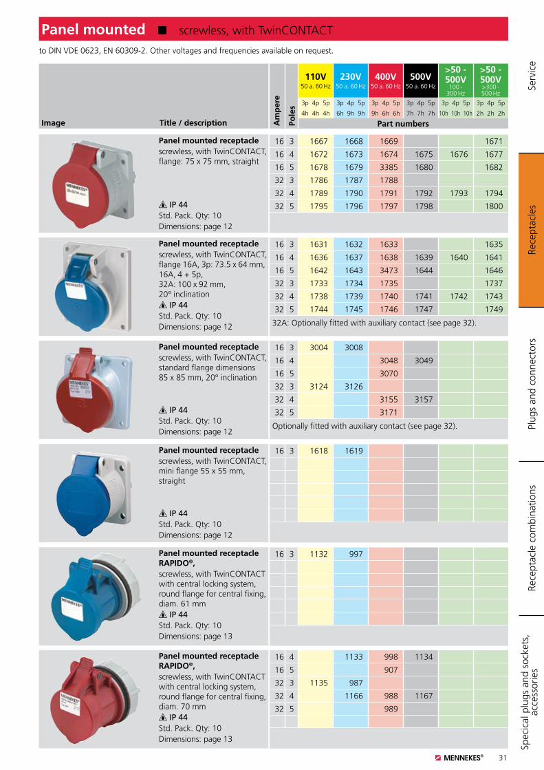
to DIN VDE 0623, EN 60309-2. Other voltages and frequencies available on request.
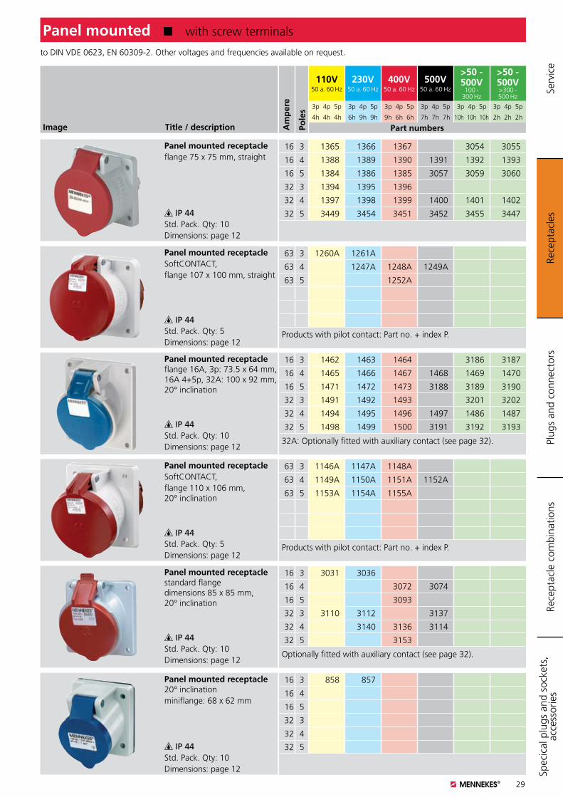
Panel mounted K with screw terminals
Panel mounted receptacleflange 75 x 75 mm, straight
IP 44Std. Pack. Qty: 10Dimensions: page 12
Panel mounted receptacleflange 16A, 3p: 73.5 x 64 mm, 16A 4+5p, 32A: 100 x 92 mm, 20° inclination
IP 44Std. Pack. Qty: 10Dimensions: page 12
16 3 1365 1366 1367 3054 3055
16 4 1388 1389 1390 1391 1392 1393
16 5 1384 1386 1385 3057 3059 3060
32 3 1394 1395 1396
32 4 1397 1398 1399 1400 1401 1402
32 5 3449 3454 3451 3452 3455 3447
16 3 1462 1463 1464 3186 3187
16 4 1465 1466 1467 1468 1469 1470
16 5 1471 1472 1473 3188 3189 3190
32 3 1491 1492 1493 3201 3202
32 4 1494 1495 1496 1497 1486 1487
32 5 1498 1499 1500 3191 3192 3193
32A: Optionally fitted with auxiliary contact (see page 32).
Panel mounted receptacleSoftCONTACT, flange 110 x 106 mm,20° inclination
IP 44Std. Pack. Qty: 5Dimensions: page 12
63 3 1146A 1147A 1148A
63 4 1149A 1150A 1151A 1152A
63 5 1153A 1154A 1155A
Products with pilot contact: Part no. + index P.
Panel mounted receptaclestandard flange dimensions 85 x 85 mm, 20° inclination
IP 44Std. Pack. Qty: 10Dimensions: page 12
16 3 3031 3036
16 4 3072 3074
16 5 3093
32 3 3110 3112 3137
32 4 3140 3136 3114
32 5 3153
Optionally fitted with auxiliary contact (see page 32).
Panel mounted receptacle20° inclination miniflange: 68 x 62 mm
IP 44Std. Pack. Qty: 10Dimensions: page 12
16 3 858 857
16 4
16 5
32 3
32 4
32 5
Panel mounted receptacleSoftCONTACT, flange 107 x 100 mm, straight
IP 44Std. Pack. Qty: 5Dimensions: page 12
63 3 1260A 1261A
63 4 1247A 1248A 1249A
63 5 1252A
Products with pilot contact: Part no. + index P.
Rece
ptac
les
Plug
s an
d co
nnec
tors
Rece
ptac
le c
ombi
natio
nsSp
ecic
al p
lugs
and
soc
kets
, ac
cess
orie
s Se
rvic
e
Am
per
e
Pole
s
110V50 a. 60 Hz
230V50 a. 60 Hz
400V50 a. 60 Hz
500V50 a. 60 Hz
>50 - 500V
100 - 300 Hz
>50 - 500V>300 - 500 Hz
3p 4p 5p 3p 4p 5p 3p 4p 5p 3p 4p 5p 3p 4p 5p 3p 4p 5p
4h 4h 4h 6h 9h 9h 9h 6h 6h 7h 7h 7h 10h 10h 10h 2h 2h 2h
Part numbers
30
Image Title / description
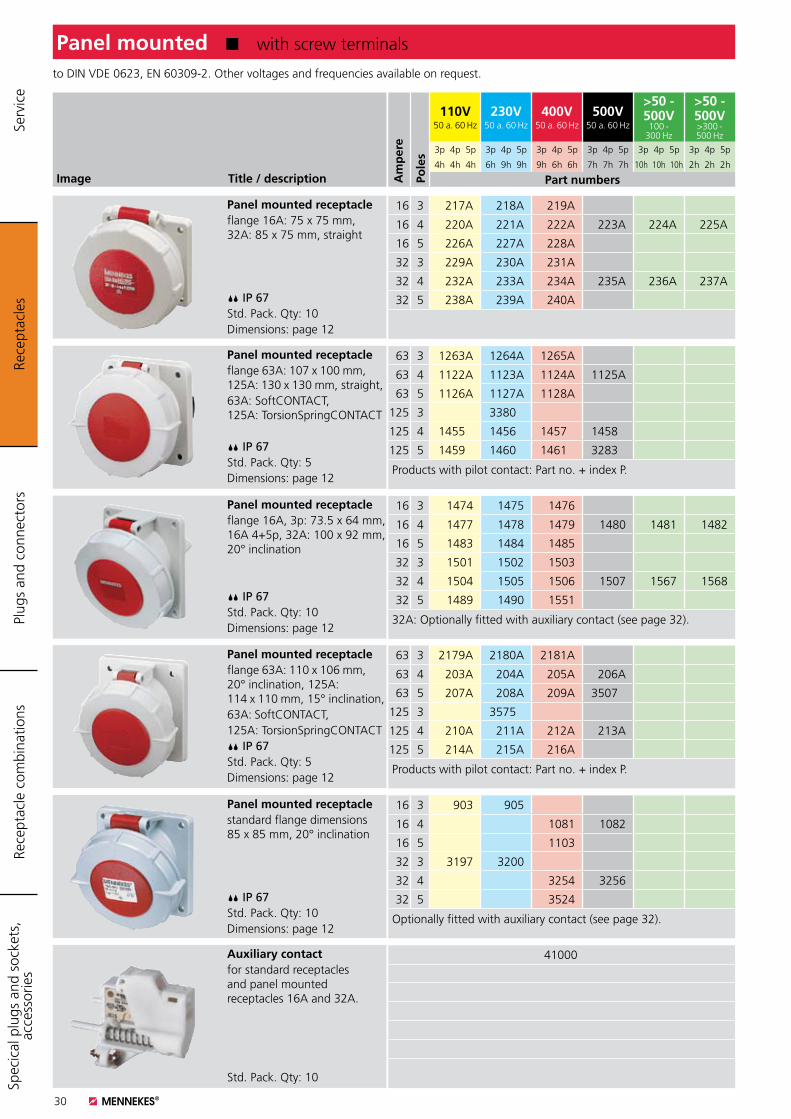
to DIN VDE 0623, EN 60309-2. Other voltages and frequencies available on request.
Panel mounted K with screw terminals
Panel mounted receptacleflange 16A: 75 x 75 mm, 32A: 85 x 75 mm, straight
IP 67Std. Pack. Qty: 10Dimensions: page 12
Panel mounted receptacleflange 63A: 107 x 100 mm, 125A: 130 x 130 mm, straight,63A: SoftCONTACT, 125A: TorsionSpringCONTACT
IP 67Std. Pack. Qty: 5Dimensions: page 12
Panel mounted receptacleflange 16A, 3p: 73.5 x 64 mm, 16A 4+5p, 32A: 100 x 92 mm, 20° inclination
IP 67Std. Pack. Qty: 10Dimensions: page 12
16 3 217A 218A 219A
16 4 220A 221A 222A 223A 224A 225A
16 5 226A 227A 228A
32 3 229A 230A 231A
32 4 232A 233A 234A 235A 236A 237A
32 5 238A 239A 240A
63 3 1263A 1264A 1265A
63 4 1122A 1123A 1124A 1125A
63 5 1126A 1127A 1128A
125 3 3380A
125 4 1455A 1456A 1457A 1458A
125 5 1459A 1460A 1461A 3283A
Products with pilot contact: Part no. + index P.
16 3 1474 1475 1476
16 4 1477 1478 1479 1480 1481 1482
16 5 1483 1484 1485
32 3 1501 1502 1503
32 4 1504 1505 1506 1507 1567 1568
32 5 1489 1490 1551
32A: Optionally fitted with auxiliary contact (see page 32).
Auxiliary contactfor standard receptacles and panel mounted receptacles 16A and 32A.
Std. Pack. Qty: 10
41000
Panel mounted receptacleflange 63A: 110 x 106 mm, 20° inclination, 125A: 114 x 110 mm, 15° inclination,63A: SoftCONTACT,125A: TorsionSpringCONTACT IP 67Std. Pack. Qty: 5Dimensions: page 12
63 3 2179A 2180A 2181A
63 4 203A 204A 205A 206A
63 5 207A 208A 209A 3507A
125 3 3575A
125 4 210A 211A 212A 213A
125 5 214A 215A 216A
Products with pilot contact: Part no. + index P.
Panel mounted receptaclestandard flange dimensions 85 x 85 mm, 20° inclination
IP 67Std. Pack. Qty: 10Dimensions: page 12
16 3 903 905
16 4 1081 1082
16 5 1103
32 3 3197 3200
32 4 3254 3256
32 5 3524
Optionally fitted with auxiliary contact (see page 32).
Rece
ptac
les
Plug
s an
d co
nnec
tors
Rece
ptac
le c
ombi
natio
nsSp
ecic
al p
lugs
and
soc
kets
, ac
cess
orie
s Se
rvic
e
Am
per
e
Pole
s
110V50 a. 60 Hz
230V50 a. 60 Hz
400V50 a. 60 Hz
500V50 a. 60 Hz
>50 - 500V
100 - 300 Hz
>50 - 500V>300 - 500 Hz
3p 4p 5p 3p 4p 5p 3p 4p 5p 3p 4p 5p 3p 4p 5p 3p 4p 5p
4h 4h 4h 6h 9h 9h 9h 6h 6h 7h 7h 7h 10h 10h 10h 2h 2h 2h
Part numbers
31
Image Title / description
to DIN VDE 0623, EN 60309-2. Other voltages and frequencies available on request.
Panel mounted K screwless, with TwinCONTACT
Panel mounted receptaclescrewless, with TwinCONTACT, mini flange 55 x 55 mm, straight
IP 44Std. Pack. Qty: 10Dimensions: page 12
Panel mounted receptacle RAPIDO®,screwless, with TwinCONTACT with central locking system, round flange for central fixing, diam. 70 mm IP 44Std. Pack. Qty: 10Dimensions: page 13
16 3 1618 1619
16 4 1133 998 1134
16 5 907
32 3 1135 987
32 4 1166 988 1167
32 5 989
Panel mounted receptaclescrewless, with TwinCONTACT, flange: 75 x 75 mm, straight
IP 44Std. Pack. Qty: 10Dimensions: page 12
Panel mounted receptaclescrewless, with TwinCONTACT, flange 16A, 3p: 73.5 x 64 mm, 16A, 4 + 5p, 32A: 100 x 92 mm, 20° inclination IP 44Std. Pack. Qty: 10Dimensions: page 12
Panel mounted receptaclescrewless, with TwinCONTACT, standard flange dimensions 85 x 85 mm, 20° inclination
IP 44Std. Pack. Qty: 10Dimensions: page 12
16 3 1667 1668 1669 1671
16 4 1672 1673 1674 1675 1676 1677
16 5 1678 1679 3385 1680 1682
32 3 1786 1787 1788
32 4 1789 1790 1791 1792 1793 1794
32 5 1795 1796 1797 1798 1800
16 3 1631 1632 1633 1635
16 4 1636 1637 1638 1639 1640 1641
16 5 1642 1643 3473 1644 1646
32 3 1733 1734 1735 1737
32 4 1738 1739 1740 1741 1742 1743
32 5 1744 1745 1746 1747 1749
32A: Optionally fitted with auxiliary contact (see page 32).
16 3 3004 3008
16 4 3048 3049
16 5 3070
32 3 3124 3126
32 4 3155 3157
32 5 3171
Optionally fitted with auxiliary contact (see page 32).
Panel mounted receptacle RAPIDO®,screwless, with TwinCONTACT with central locking system, round flange for central fixing, diam. 61 mm IP 44Std. Pack. Qty: 10Dimensions: page 13
16 3 1132 997
Rece
ptac
les
Plug
s an
d co
nnec
tors
Rece
ptac
le c
ombi
natio
nsSp
ecic
al p
lugs
and
soc
kets
, ac
cess
orie
s Se
rvic
e
Am
per
e
Pole
s
110V50 a. 60 Hz
230V50 a. 60 Hz
400V50 a. 60 Hz
500V50 a. 60 Hz
>50 - 500V
100 - 300 Hz
>50 - 500V>300 - 500 Hz
3p 4p 5p 3p 4p 5p 3p 4p 5p 3p 4p 5p 3p 4p 5p 3p 4p 5p
4h 4h 4h 6h 9h 9h 9h 6h 6h 7h 7h 7h 10h 10h 10h 2h 2h 2h
Part numbers
32
Image Title / description
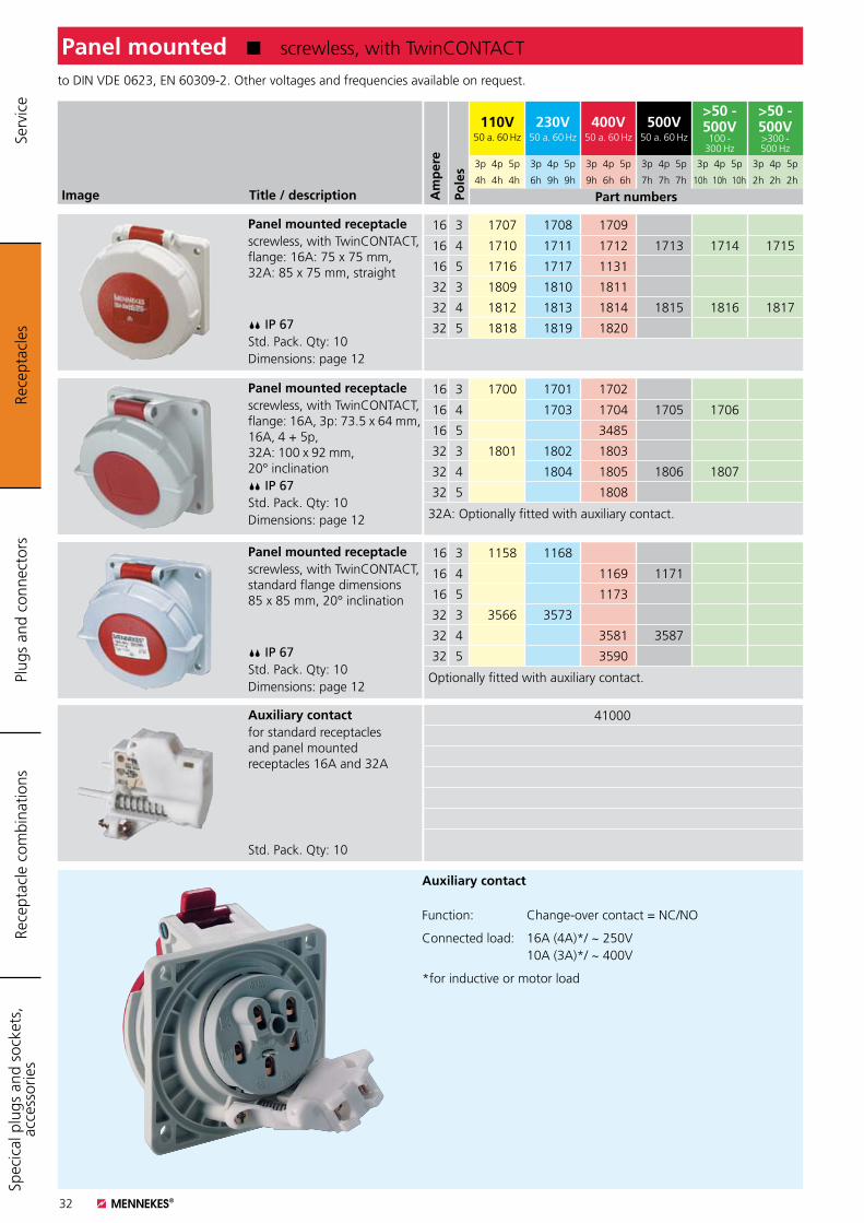
to DIN VDE 0623, EN 60309-2. Other voltages and frequencies available on request.
Panel mounted K screwless, with TwinCONTACT
Panel mounted receptaclescrewless, with TwinCONTACT, flange: 16A: 75 x 75 mm, 32A: 85 x 75 mm, straight
IP 67Std. Pack. Qty: 10Dimensions: page 12
Panel mounted receptaclescrewless, with TwinCONTACT, flange: 16A, 3p: 73.5 x 64 mm, 16A, 4 + 5p, 32A: 100 x 92 mm, 20° inclination IP 67Std. Pack. Qty: 10Dimensions: page 12
Panel mounted receptaclescrewless, with TwinCONTACT, standard flange dimensions 85 x 85 mm, 20° inclination
IP 67Std. Pack. Qty: 10Dimensions: page 12
16 3 1707 1708 1709
16 4 1710 1711 1712 1713 1714 1715
16 5 1716 1717 1131
32 3 1809 1810 1811
32 4 1812 1813 1814 1815 1816 1817
32 5 1818 1819 1820
16 3 1700 1701 1702
16 4 1703 1704 1705 1706
16 5 3485
32 3 1801 1802 1803
32 4 1804 1805 1806 1807
32 5 1808
32A: Optionally fitted with auxiliary contact.
16 3 1158 1168
16 4 1169 1171
16 5 1173
32 3 3566 3573
32 4 3581 3587
32 5 3590
Optionally fitted with auxiliary contact.
Auxiliary contactfor standard receptacles and panel mounted receptacles 16A and 32A
Std. Pack. Qty: 10
41000
Auxiliary contact
Function: Change-over contact = NC/NO
Connected load: 16A (4A)*/ ~ 250V 10A (3A)*/ ~ 400V
*for inductive or motor load
Rece
ptac
les
Plug
s an
d co
nnec
tors
Rece
ptac
le c
ombi
natio
nsSp
ecic
al p
lugs
and
soc
kets
, ac
cess
orie
s Se
rvic
e
Am
per
e
Pole
s
110V50 a. 60 Hz
230V50 a. 60 Hz
400V50 a. 60 Hz
500V50 a. 60 Hz
>50 - 500V
100 - 300 Hz
>50 - 500V>300 - 500 Hz
3p 4p 5p 3p 4p 5p 3p 4p 5p 3p 4p 5p 3p 4p 5p 3p 4p 5p
4h 4h 4h 6h 9h 9h 9h 6h 6h 7h 7h 7h 10h 10h 10h 2h 2h 2h
Part numbers
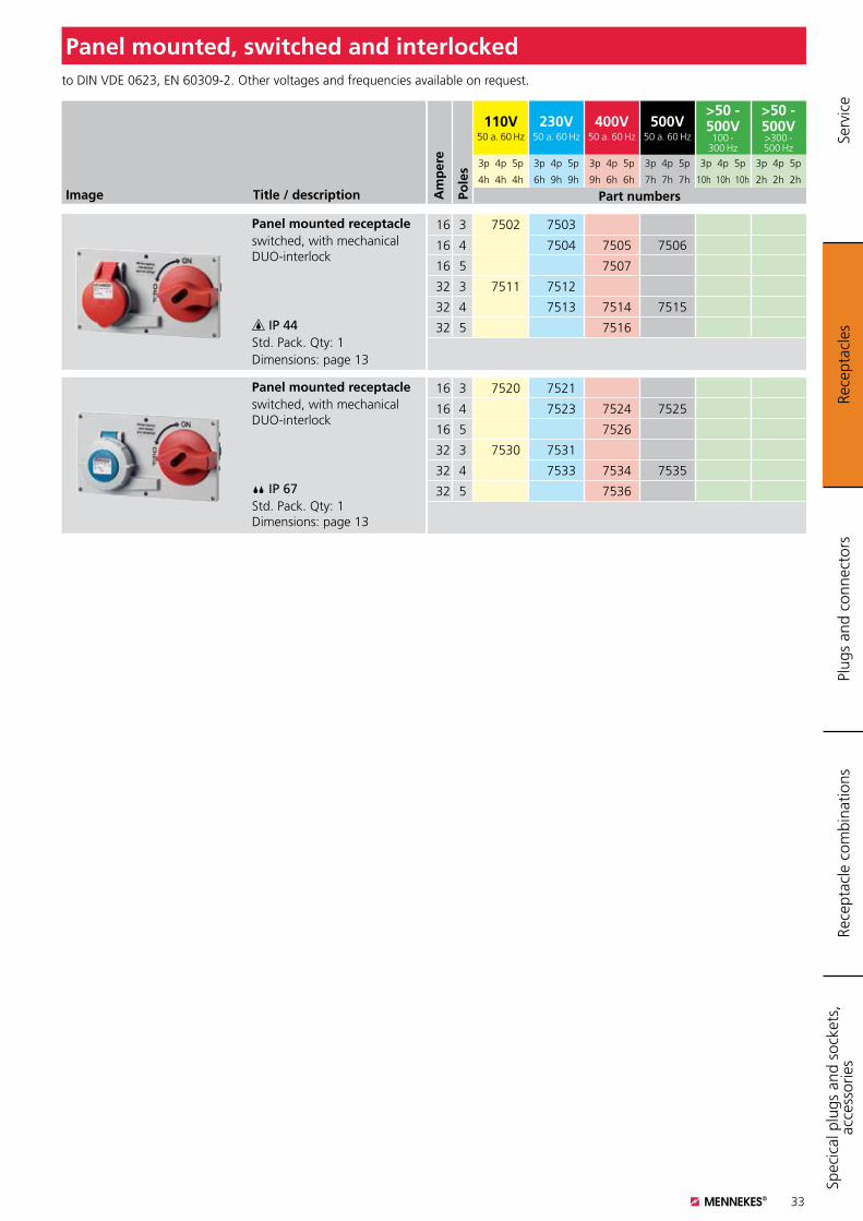
33
Image Title / description
Panel mounted receptacleswitched, with mechanical DUO-interlock
IP 44Std. Pack. Qty: 1Dimensions: page 13
to DIN VDE 0623, EN 60309-2. Other voltages and frequencies available on request.
Panel mounted, switched and interlocked
16 3 7502 7503
16 4 7504 7505 7506
16 5 7507
32 3 7511 7512
32 4 7513 7514 7515
32 5 7516
Panel mounted receptacleswitched, with mechanical DUO-interlock
IP 67Std. Pack. Qty: 1 Dimensions: page 13
16 3 7520 7521
16 4 7523 7524 7525
16 5 7526
32 3 7530 7531
32 4 7533 7534 7535
32 5 7536
Rece
ptac
les
Plug
s an
d co
nnec
tors
Rece
ptac
le c
ombi
natio
nsSp
ecic
al p
lugs
and
soc
kets
, ac
cess
orie
s Se
rvic
e
Am
per
e
Pole
s
110V50 a. 60 Hz
230V50 a. 60 Hz
400V50 a. 60 Hz
500V50 a. 60 Hz
>50 - 500V
100 - 300 Hz
>50 - 500V>300 - 500 Hz
3p 4p 5p 3p 4p 5p 3p 4p 5p 3p 4p 5p 3p 4p 5p 3p 4p 5p
4h 4h 4h 6h 9h 9h 9h 6h 6h 7h 7h 7h 10h 10h 10h 2h 2h 2h
Part numbers
34
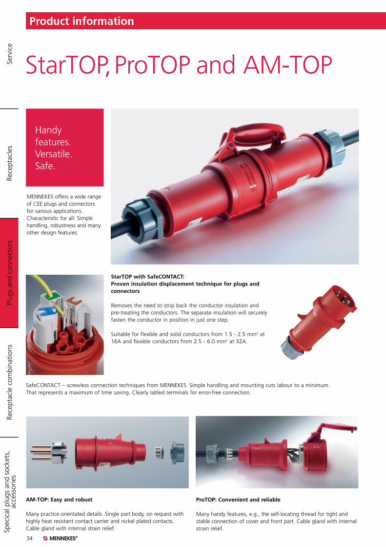
SafeCONTACT – screwless connection techniques from MENNEKES. Simple handling and mounting cuts labour to a minimum. That represents a maximum of time saving. Clearly labled terminals for error-free connection.
StarTOP with SafeCONTACT:Proven insulation displacement technique for plugs and connectors
Removes the need to strip back the conductor insulation and pre-treating the conductors. The separate insulation will securely fasten the conductor in position in just one step.
Suitable for flexible and solid conductors from 1.5 - 2.5 mm2 at 16A and flexible conductors from 2.5 - 6.0 mm2 at 32A.
StarTOP, ProTOP and AM-TOP
MENNEKES offers a wide range of CEE plugs and connectors for various applications. Characteristic for all: Simple handling, robustness and many other design features.
Handy features. Versatile. Safe.
AM-TOP: Easy and robust
Many practice orientated details. Single part body, on request with highly heat resistant contact carrier and nickel plated contacts. Cable gland with internal strain relief.
ProTOP: Convenient and reliable Many handy features, e.g., the self-locating thread for tight and stable connection of cover and front part. Cable gland with internal strain relief.
Product information Pl
ugs
and
conn
ecto
rsRe
cept
acle
sRe
cept
acle
com
bina
tions
Spec
ical
plu
gs a
nd s
ocke
ts,
acce
ssor
ies
Serv
ice

35
PowerTOP Xtra. Extra slip-proof. Extra shock- resistant. Extra protected.
PowerTOP Xtra
Plugs and connectors for toughest conditions – that´s PowerTOP Xtra. The unique rubber coating of the contact surfaces and the ergonomic design guarantees best grip – even with working gloves.
Tough
The plugs provide better corrosion protection thanks to nickel plated contacts. More safety through highly heat resistant contact carrier.
Easy and fast installation
K Substantially reduced installation times through largely tool-free installation. K Locking slides instead of screws and especially smooth cable gland with integrated strain relief, seal and protection against kinking.
Always clean, always safe K As the cable glands are in contact with the body of the plug and connector, the areas for the ingress of dirt are reduced and allow for easy cleaning in areas where hygiene is of prime importance. K Moulded seals in the connector lid and the front part of the plug.K Integrated opening aid on the connector lid.
K Connectors with highly heat resistant contact carrier; nickel plated contact sleeves also available on request. Pilot contact standard with plugs; optionally available for connectors.
K Comfortable self-locating thread lock between front and back part.
K Stable and fast locking without screws. Unlocking only with just a tool according to the regulations.
K Secure contact as well as convenient inserting and withdrawal through SoftCONTACT at 63A and TorsionSpringCONTACT at 125A.
Product information
Plug
s an
d co
nnec
tors
Rece
ptac
les
Rece
ptac
le c
ombi
natio
nsSp
ecic
al p
lugs
and
soc
kets
, ac
cess
orie
s Se
rvic
e
36
Image Title / description
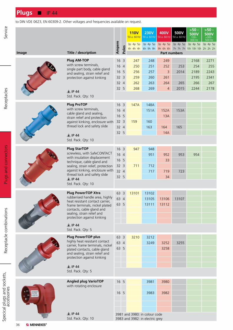
Plug AM-TOPwith screw terminals, single part body, cable gland and sealing, strain relief and protection against kinking
IP 44Std. Pack. Qty: 10
Plug ProTOPwith screw terminals, cable gland and sealing, strain relief and protection against kinking, enclosure with thread lock and safety slide
IP 44Std. Pack. Qty: 10
Plug StarTOPscrewless, with SafeCONTACT with insulation displacement technique, cable gland and sealing, strain relief, protection against kinking, enclosure with thread lock and safety slide IP 44Std. Pack. Qty: 10
Plug PowerTOP Xtra rubberised handle area, highly heat resistant contact carrier, frame terminals, nickel plated contacts, cable gland and sealing, strain relief and protection against kinking
IP 44Std. Pack. Qty: 5
Angled plug VarioTOPwith rotating enclosure
IP 44Std. Pack. Qty: 10
to DIN VDE 0623, EN 60309-2. Other voltages and frequencies available on request.
Plugs K IP 44
16 3 247 248 249 2168 2271
16 4 250 251 252 253 254 255
16 5 256 257 3 2014 2189 2243
32 3 259 260 261 2195 2341
32 4 262 263 264 265 266 267
32 5 268 269 4 2015 2244 2178
16 3 147A 148A
16 4 151A 152A 153A
16 5 13A
32 3 159A 160A
32 4 163A 164A 165A
32 5 14A
16 3 947 948
16 4 951 952 953 954
16 5 33
32 3 711 712
32 4 717 719 723
32 5 34
63 3 13101 13102
63 4 13105 13106 13107
63 5 13111 13112
16 5 3981 3980
16 5 3983 3982
3981 and 3980: in colour code3983 and 3982: in electric grey
Plug
s an
d co
nnec
tors
Rece
ptac
les
Rece
ptac
le c
ombi
natio
nsSp
ecic
al p
lugs
and
soc
kets
, ac
cess
orie
s Se
rvic
e
Am
per
e
Pole
s
110V50 a. 60 Hz
230V50 a. 60 Hz
400V50 a. 60 Hz
500V50 a. 60 Hz
>50 - 500V
100 - 300 Hz
>50 - 500V>300 - 500 Hz
3p 4p 5p 3p 4p 5p 3p 4p 5p 3p 4p 5p 3p 4p 5p 3p 4p 5p
4h 4h 4h 6h 9h 9h 9h 6h 6h 7h 7h 7h 10h 10h 10h 2h 2h 2h
Part numbers
Plug PowerTOP plus highly heat resistant contact carrier, frame terminals, nickel plated contacts, cable gland and sealing, strain relief and protection against kinking
IP 44Std. Pack. Qty: 5
63 3 3210 3212
63 4 3249 3252 3255
63 5 3258
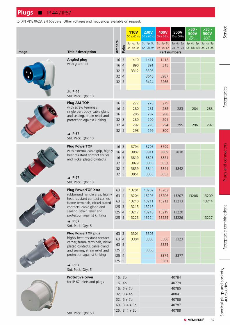
37
Angled plugwith grommet
IP 44Std. Pack. Qty: 10
16 3 1410 1411 1412
16 4 890 891 315
32 3 3312 3306
32 4 3646 3987
32 5 3424 3266
Image Title / description
Plug AM-TOPwith screw terminals, single part body, cable gland and sealing, strain relief and protection against kinking
IP 67Std. Pack. Qty: 10
Plug PowerTOP with external cable grip, highly heat resistant contact carrier and nickel plated contacts
IP 67Std. Pack. Qty: 10
Plug PowerTOP Xtra rubberised handle area, highly heat resistant contact carrier, frame terminals, nickel plated contacts, cable gland and sealing, strain relief and protection against kinking
IP 67Std. Pack. Qty: 5
Protective coverfor IP 67 inlets and plugs
Std. Pack. Qty: 50
to DIN VDE 0623, EN 60309-2. Other voltages and frequencies available on request.
16 3 277 278 279
16 4 280 281 282 283 284 285
16 5 286 287 288
32 3 289 290 291
32 4 292 293 294 295 296 297
32 5 298 299 300
16 3 3794 3796 3799
16 4 3807 3811 3809 3810
16 5 3819 3823 3821
32 3 3829 3830 3832
32 4 3839 3844 3841 3842
32 5 3851 3855 3853
63 3 13201 13202 13203
63 4 13204 13205 13206 13207 13208 13209
63 5 13210 13211 13212 13213 13214
125 3 13215 13216
125 4 13217 13218 13219 13220
125 5 13223 13224 13225 13226 13227
16, 3p 40784
16, 4p 40778
16, 5 + 7p 40785
32, 3 + 4p 40841
32, 5 + 7p 40786
63, 3, 4 + 5p 40787
125, 3, 4 + 5p 40788
Plugs K IP 44 / IP67
Plug
s an
d co
nnec
tors
Rece
ptac
les
Rece
ptac
le c
ombi
natio
nsSp
ecic
al p
lugs
and
soc
kets
, ac
cess
orie
s Se
rvic
e
Am
per
e
Pole
s
110V50 a. 60 Hz
230V50 a. 60 Hz
400V50 a. 60 Hz
500V50 a. 60 Hz
>50 - 500V
100 - 300 Hz
>50 - 500V>300 - 500 Hz
3p 4p 5p 3p 4p 5p 3p 4p 5p 3p 4p 5p 3p 4p 5p 3p 4p 5p
4h 4h 4h 6h 9h 9h 9h 6h 6h 7h 7h 7h 10h 10h 10h 2h 2h 2h
Part numbers
Plug PowerTOP plus highly heat resistant contact carrier, frame terminals, nickel plated contacts, cable gland and sealing, strain relief and protection against kinking
IP 67Std. Pack. Qty: 5
63 3 3301 3303
63 4 3304 3305 3308 3323
63 5 3325
125 3 3358
125 4 3374 3377
125 5 3381
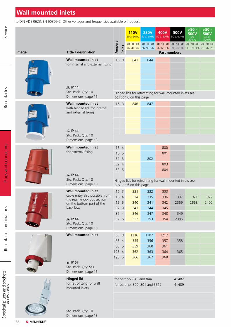
38
Image Title / description
Wall mounted inlet for internal and external fixing
IP 44Std. Pack. Qty: 10Dimensions: page 13
Wall mounted inlet with hinged lid, for internal and external fixing
IP 44Std. Pack. Qty: 10Dimensions: page 13
Wall mounted inlet for external fixing
IP 44Std. Pack. Qty: 10Dimensions: page 13
Wall mounted inlet cable entry also possible from the rear, knock-out section on the bottom part of the back box
IP 44Std. Pack. Qty: 10Dimensions: page 13
to DIN VDE 0623, EN 60309-2. Other voltages and frequencies available on request.
Wall mounted inlets
16 3 843 844
Hinged lids for retrofitting for wall mounted inlets see position 6 on this page.
16 3 846 847
16 4 800
16 5 801
32 3 802
32 4 803
32 5 804
Hinged lids for retrofitting for wall mounted inlets see position 6 on this page.
16 3 331 332 333
16 4 334 335 336 337 921 922
16 5 340 341 342 2359 2668 2400
32 3 343 344 345
32 4 346 347 348 349
32 5 352 353 354 2386
Wall mounted inlet
IP 67Std. Pack. Qty: 5/3Dimensions: page 13
63 3 1216 1107 1217
63 4 355 356 357 358
63 5 359 360 361
125 4 362 363 364 365
125 5 366 367 368
Hinged lidfor retrofitting for wall mounted inlets
Std. Pack. Qty: 10Dimensions: page 13
for part no. 843 and 844 41482
for part no. 800, 801 and 3517 41489
Plug
s an
d co
nnec
tors
Rece
ptac
les
Rece
ptac
le c
ombi
natio
nsSp
ecic
al p
lugs
and
soc
kets
, ac
cess
orie
s Se
rvic
e
Am
per
e
Pole
s
110V50 a. 60 Hz
230V50 a. 60 Hz
400V50 a. 60 Hz
500V50 a. 60 Hz
>50 - 500V
100 - 300 Hz
>50 - 500V>300 - 500 Hz
3p 4p 5p 3p 4p 5p 3p 4p 5p 3p 4p 5p 3p 4p 5p 3p 4p 5p
4h 4h 4h 6h 9h 9h 9h 6h 6h 7h 7h 7h 10h 10h 10h 2h 2h 2h
Part numbers
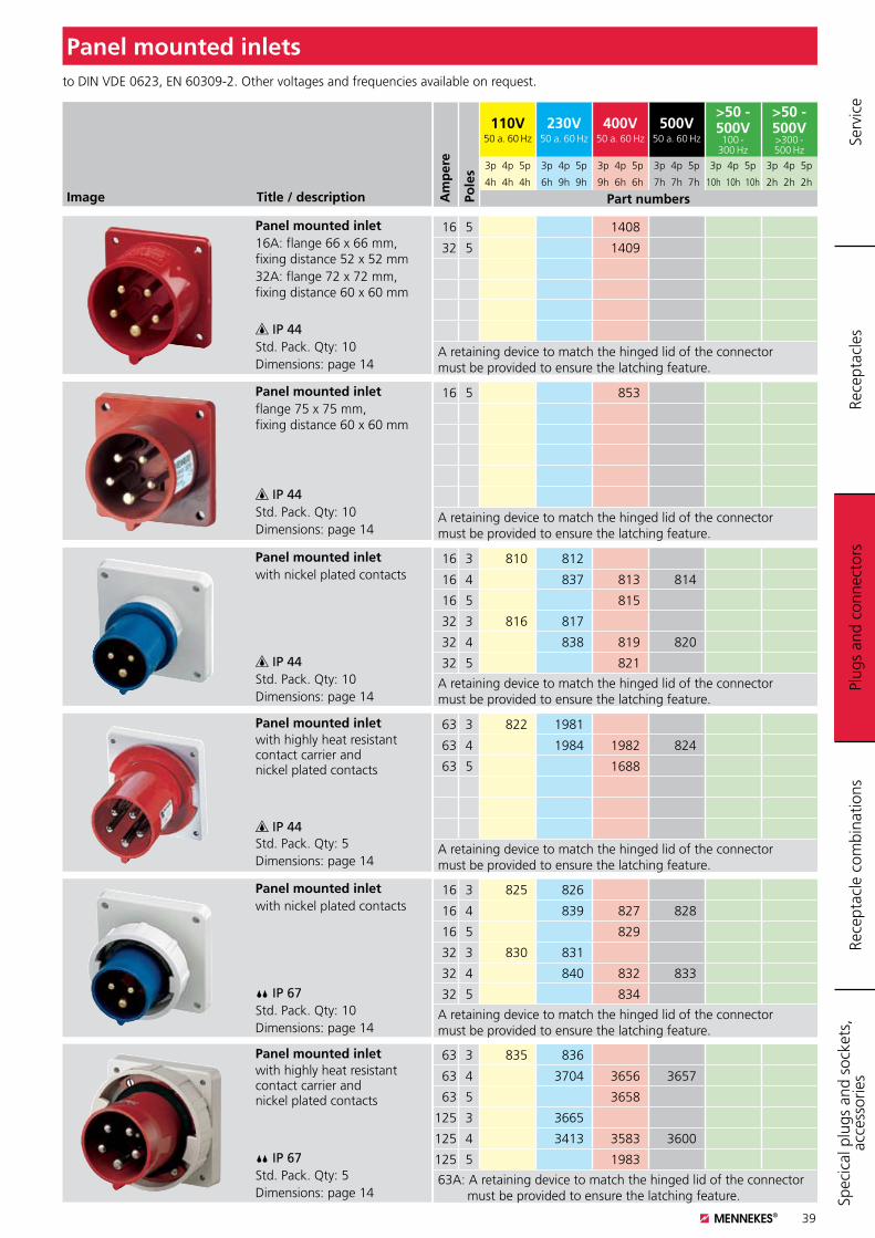
39
Image Title / description
Panel mounted inlet 16A: flange 66 x 66 mm, fixing distance 52 x 52 mm32A: flange 72 x 72 mm, fixing distance 60 x 60 mm
IP 44Std. Pack. Qty: 10Dimensions: page 14
Panel mounted inlet flange 75 x 75 mm, fixing distance 60 x 60 mm
IP 44Std. Pack. Qty: 10Dimensions: page 14
Panel mounted inlet with nickel plated contacts
IP 44Std. Pack. Qty: 10Dimensions: page 14
Panel mounted inlet with highly heat resistant contact carrier and nickel plated contacts
IP 44Std. Pack. Qty: 5Dimensions: page 14
to DIN VDE 0623, EN 60309-2. Other voltages and frequencies available on request.
Panel mounted inlets
16 5 1408
32 5 1409
A retaining device to match the hinged lid of the connector must be provided to ensure the latching feature.
16 5 853
A retaining device to match the hinged lid of the connector must be provided to ensure the latching feature.
16 3 810 812
16 4 837 813 814
16 5 815
32 3 816 817
32 4 838 819 820
32 5 821
A retaining device to match the hinged lid of the connector must be provided to ensure the latching feature.
63 3 822 1981
63 4 1984 1982 824
63 5 1688
A retaining device to match the hinged lid of the connector must be provided to ensure the latching feature.
Panel mounted inletwith nickel plated contacts
IP 67Std. Pack. Qty: 10Dimensions: page 14
16 3 825 826
16 4 839 827 828
16 5 829
32 3 830 831
32 4 840 832 833
32 5 834
A retaining device to match the hinged lid of the connector must be provided to ensure the latching feature.
Panel mounted inletwith highly heat resistant contact carrier and nickel plated contacts
IP 67Std. Pack. Qty: 5Dimensions: page 14
63 3 835 836
63 4 3704 3656 3657
63 5 3658
125 3 3665
125 4 3413 3583 3600
125 5 1983
63A: A retaining device to match the hinged lid of the connector must be provided to ensure the latching feature.
Plug
s an
d co
nnec
tors
Rece
ptac
les
Rece
ptac
le c
ombi
natio
nsSp
ecic
al p
lugs
and
soc
kets
, ac
cess
orie
s Se
rvic
e
Am
per
e
Pole
s
110V50 a. 60 Hz
230V50 a. 60 Hz
400V50 a. 60 Hz
500V50 a. 60 Hz
>50 - 500V
100 - 300 Hz
>50 - 500V>300 - 500 Hz
3p 4p 5p 3p 4p 5p 3p 4p 5p 3p 4p 5p 3p 4p 5p 3p 4p 5p
4h 4h 4h 6h 9h 9h 9h 6h 6h 7h 7h 7h 10h 10h 10h 2h 2h 2h
Part numbers
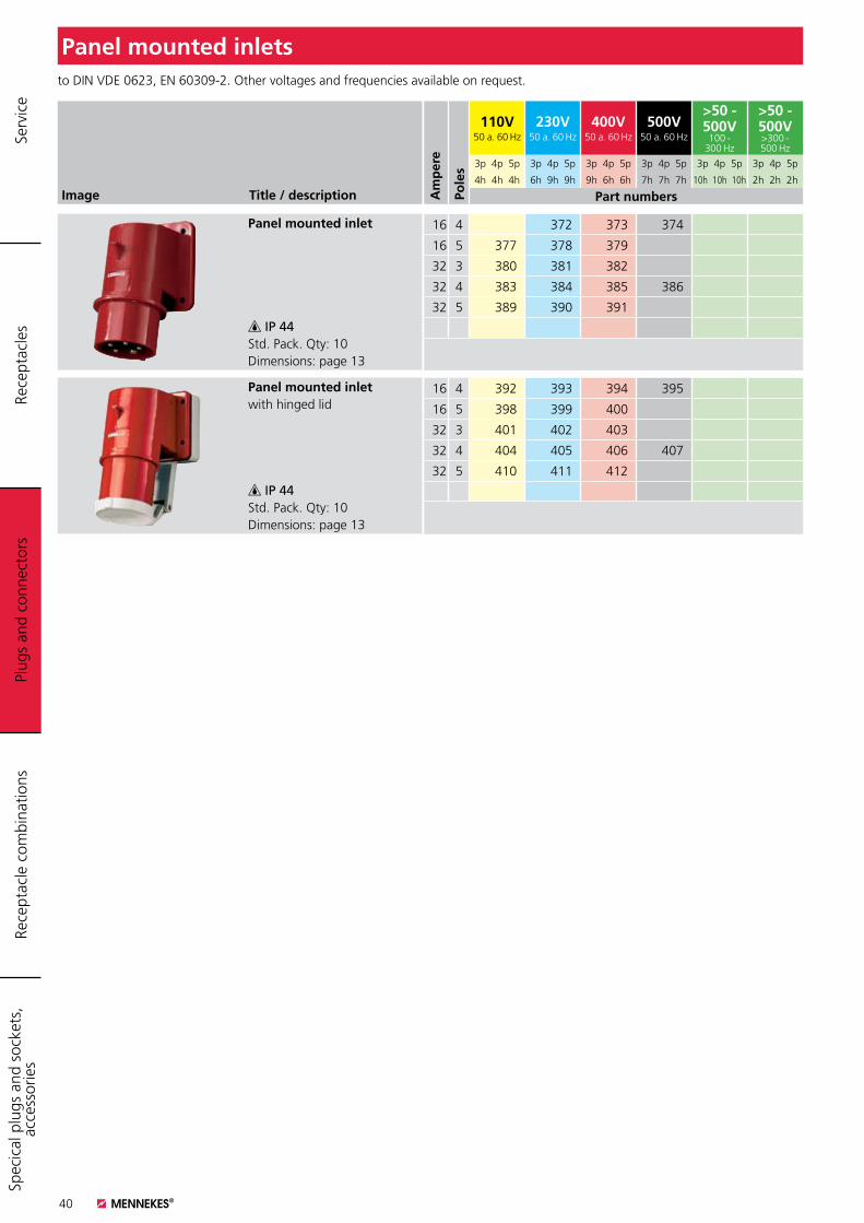
40
Image Title / description
Panel mounted inlet
IP 44Std. Pack. Qty: 10Dimensions: page 13
Panel mounted inlet with hinged lid
IP 44Std. Pack. Qty: 10Dimensions: page 13
to DIN VDE 0623, EN 60309-2. Other voltages and frequencies available on request.
Panel mounted inlets
16 4 372 373 374
16 5 377 378 379
32 3 380 381 382
32 4 383 384 385 386
32 5 389 390 391
16 4 392 393 394 395
16 5 398 399 400
32 3 401 402 403
32 4 404 405 406 407
32 5 410 411 412
Plug
s an
d co
nnec
tors
Rece
ptac
les
Rece
ptac
le c
ombi
natio
nsSp
ecic
al p
lugs
and
soc
kets
, ac
cess
orie
s Se
rvic
e
Am
per
e
Pole
s
110V50 a. 60 Hz
230V50 a. 60 Hz
400V50 a. 60 Hz
500V50 a. 60 Hz
>50 - 500V
100 - 300 Hz
>50 - 500V>300 - 500 Hz
3p 4p 5p 3p 4p 5p 3p 4p 5p 3p 4p 5p 3p 4p 5p 3p 4p 5p
4h 4h 4h 6h 9h 9h 9h 6h 6h 7h 7h 7h 10h 10h 10h 2h 2h 2h
Part numbers
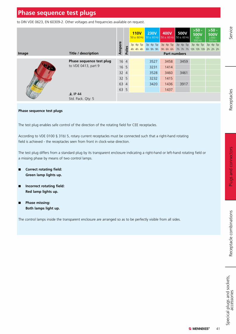
41
Image Title / description
Phase sequence test plug to VDE 0413, part 9
IP 44Std. Pack. Qty: 5
to DIN VDE 0623, EN 60309-2. Other voltages and frequencies available on request.
Phase sequence test plugs
16 4 3527 3458 3459
16 5 3231 1414
32 4 3528 3460 3461
32 5 3232 1415
63 4 3420 1436 3917
63 5 1437
Phase sequence test plugs
The test plug enables safe control of the direction of the rotating field for CEE receptacles.
According to VDE 0100 § 31b) 5, rotary current receptacles must be connected such that a right-hand rotating
field is achieved - the receptacles seen from front in clock-wise direction.
The test plug differs from a standard plug by its transparent enclosure indicating a right-hand or left-hand rotating field or
a missing phase by means of two control lamps.
K Correct rotating field:
Green lamp lights up.
K Incorrect rotating field:
Red lamp lights up.
K Phase missing:
Both lamps light up.
The control lamps inside the transparent enclosure are arranged so as to be perfectly visible from all sides.
Plug
s an
d co
nnec
tors
Rece
ptac
les
Rece
ptac
le c
ombi
natio
nsSp
ecic
al p
lugs
and
soc
kets
, ac
cess
orie
s Se
rvic
e
Am
per
e
Pole
s
110V50 a. 60 Hz
230V50 a. 60 Hz
400V50 a. 60 Hz
500V50 a. 60 Hz
>50 - 500V
100 - 300 Hz
>50 - 500V>300 - 500 Hz
3p 4p 5p 3p 4p 5p 3p 4p 5p 3p 4p 5p 3p 4p 5p 3p 4p 5p
4h 4h 4h 6h 9h 9h 9h 6h 6h 7h 7h 7h 10h 10h 10h 2h 2h 2h
Part numbers
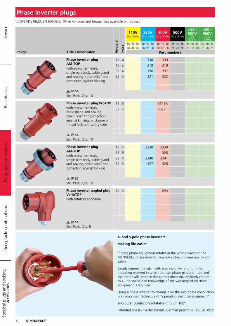
Plug
s an
d co
nnec
tors
42
Image Title / description
Phase inverter plug AM-TOPwith screw terminals, single part body, cable gland and sealing, strain relief and protection against kinking
IP 44Std. Pack. Qty: 10
Phase inverter plug ProTOPwith screw terminals, cable gland and sealing, strain relief and protection against kinking, enclosure with thread lock and safety slide
IP 44Std. Pack. Qty: 10
Phase inverter plug AM-TOPwith screw terminals, single part body, cable gland and sealing, strain relief and protection against kinking
IP 67Std. Pack. Qty: 10
Phase inverter angled plug VarioTOP with rotating enclosure
IP 44Std. Pack. Qty: 5
to DIN VDE 0623, EN 60309-2. Other voltages and frequencies available on request.
Phase inverter plugs
16 4 338 339
16 5 318 319
32 4 396 397
32 5 321 322
16 5 3319A
32 5 3322A
16 4 3338 3339
16 5 325
32 4 3340 3341
32 5 327 328
16 5 859
4- and 5-pole phase inverters -
making life easier
If three phase equipment rotates in the wrong direction the MENNEKES phase inverter plug solves the problem rapidly and safely.
Simply depress the latch with a screw-driver and turn the insulating element in which the two phase pins are fitted and the motor will rotate in the correct direction. Anybody can do this – no specialised knowledge of the workings of electrical equipment is required.
Using a phase inverter to change over the two phase conductors is a recognised technique of “operating electrical equipment“.
Two outer conductors rotatable through 180°.
Patented phase-inverter system. German patent no. 196 45 852.
Plug
s an
d co
nnec
tors
Rece
ptac
les
Rece
ptac
le c
ombi
natio
nsSp
ecic
al p
lugs
and
soc
kets
, ac
cess
orie
s Se
rvic
e
Am
per
e
Pole
s
110V50 a. 60 Hz
230V50 a. 60 Hz
400V50 a. 60 Hz
500V50 a. 60 Hz
>50 - 500V
100 - 300 Hz
>50 - 500V>300 - 500 Hz
3p 4p 5p 3p 4p 5p 3p 4p 5p 3p 4p 5p 3p 4p 5p 3p 4p 5p
4h 4h 4h 6h 9h 9h 9h 6h 6h 7h 7h 7h 10h 10h 10h 2h 2h 2h
Part numbers
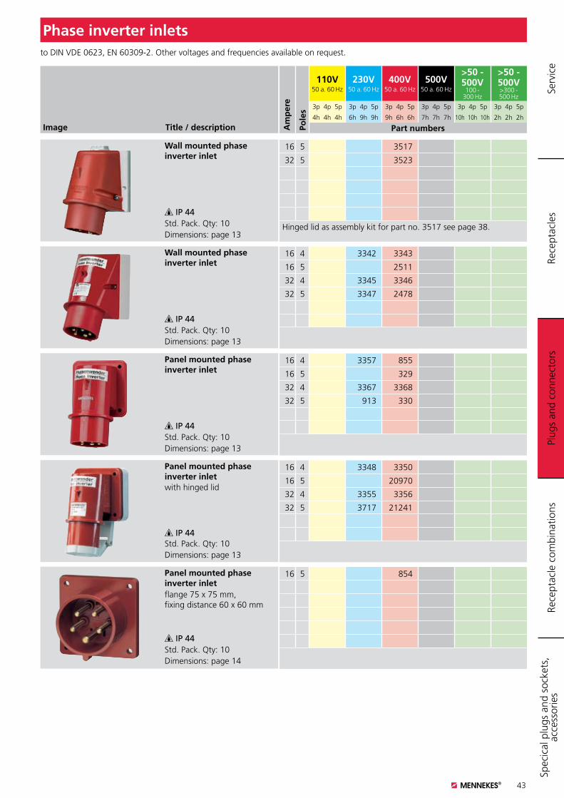
Plug
s an
d co
nnec
tors
43
Image Title / description
Wall mounted phase inverter inlet
IP 44Std. Pack. Qty: 10Dimensions: page 13
Wall mounted phase inverter inlet
IP 44Std. Pack. Qty: 10Dimensions: page 13
Panel mounted phase inverter inlet
IP 44Std. Pack. Qty: 10Dimensions: page 13
Panel mounted phase inverter inlet with hinged lid
IP 44Std. Pack. Qty: 10Dimensions: page 13
to DIN VDE 0623, EN 60309-2. Other voltages and frequencies available on request.
Phase inverter inlets
16 5 3517
32 5 3523
Hinged lid as assembly kit for part no. 3517 see page 38.
16 4 3342 3343
16 5 2511
32 4 3345 3346
32 5 3347 2478
16 4 3357 855
16 5 329
32 4 3367 3368
32 5 913 330
16 4 3348 3350
16 5 20970
32 4 3355 3356
32 5 3717 21241
Panel mounted phase inverter inletflange 75 x 75 mm, fixing distance 60 x 60 mm
IP 44Std. Pack. Qty: 10Dimensions: page 14
16 5 854
Plug
s an
d co
nnec
tors
Rece
ptac
les
Rece
ptac
le c
ombi
natio
nsSp
ecic
al p
lugs
and
soc
kets
, ac
cess
orie
s Se
rvic
e
Am
per
e
Pole
s
110V50 a. 60 Hz
230V50 a. 60 Hz
400V50 a. 60 Hz
500V50 a. 60 Hz
>50 - 500V
100 - 300 Hz
>50 - 500V>300 - 500 Hz
3p 4p 5p 3p 4p 5p 3p 4p 5p 3p 4p 5p 3p 4p 5p 3p 4p 5p
4h 4h 4h 6h 9h 9h 9h 6h 6h 7h 7h 7h 10h 10h 10h 2h 2h 2h
Part numbers
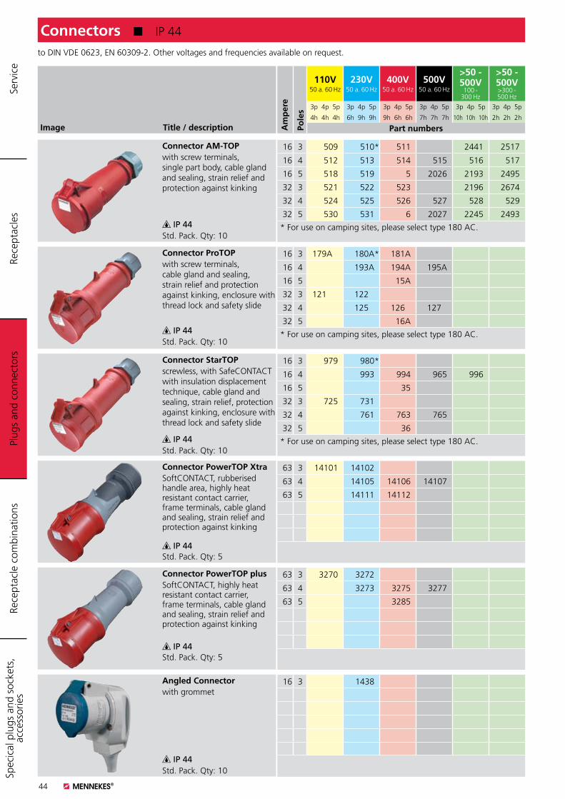
44
Image Title / description
Connector AM-TOPwith screw terminals, single part body, cable gland and sealing, strain relief and protection against kinking
IP 44Std. Pack. Qty: 10
Connector ProTOPwith screw terminals, cable gland and sealing, strain relief and protection against kinking, enclosure with thread lock and safety slide
IP 44Std. Pack. Qty: 10
Connector StarTOPscrewless, with SafeCONTACT with insulation displacement technique, cable gland and sealing, strain relief, protection against kinking, enclosure with thread lock and safety slide
IP 44Std. Pack. Qty: 10
Connector PowerTOP Xtra SoftCONTACT, rubberised handle area, highly heat resistant contact carrier, frame terminals, cable gland and sealing, strain relief and protection against kinking
IP 44Std. Pack. Qty: 5
Angled Connectorwith grommet
IP 44Std. Pack. Qty: 10
to DIN VDE 0623, EN 60309-2. Other voltages and frequencies available on request.
Connectors K IP 44
16 3 509 510* 511 2441 2517
16 4 512 513 514 515 516 517
16 5 518 519 5 2026 2193 2495
32 3 521 522 523 2196 2674
32 4 524 525 526 527 528 529
32 5 530 531 6 2027 2245 2493
* For use on camping sites, please select type 180 AC.
16 3 179AA 180A* 181A
16 4 193A 194A 195A
16 5 15A
32 3 121AA 122A
32 4 125A 126A 127A
32 5 16A
* For use on camping sites, please select type 180 AC.
16 3 979 980*
16 4 993 994 965 996
16 5 35
32 3 725 731
32 4 761 763 765
32 5 36
* For use on camping sites, please select type 180 AC.
63 3 14101 14102
63 4 14105 14106 14107
63 5 14111 14112
16 3 1438
Plug
s an
d co
nnec
tors
Rece
ptac
les
Rece
ptac
le c
ombi
natio
nsSp
ecic
al p
lugs
and
soc
kets
, ac
cess
orie
s Se
rvic
e
Am
per
e
Pole
s
110V50 a. 60 Hz
230V50 a. 60 Hz
400V50 a. 60 Hz
500V50 a. 60 Hz
>50 - 500V
100 - 300 Hz
>50 - 500V>300 - 500 Hz
3p 4p 5p 3p 4p 5p 3p 4p 5p 3p 4p 5p 3p 4p 5p 3p 4p 5p
4h 4h 4h 6h 9h 9h 9h 6h 6h 7h 7h 7h 10h 10h 10h 2h 2h 2h
Part numbers
Connector PowerTOP plus SoftCONTACT, highly heat resistant contact carrier, frame terminals, cable gland and sealing, strain relief and protection against kinking
IP 44Std. Pack. Qty: 5
63 3 3270 3272
63 4 3273 3275 3277
63 5 3285
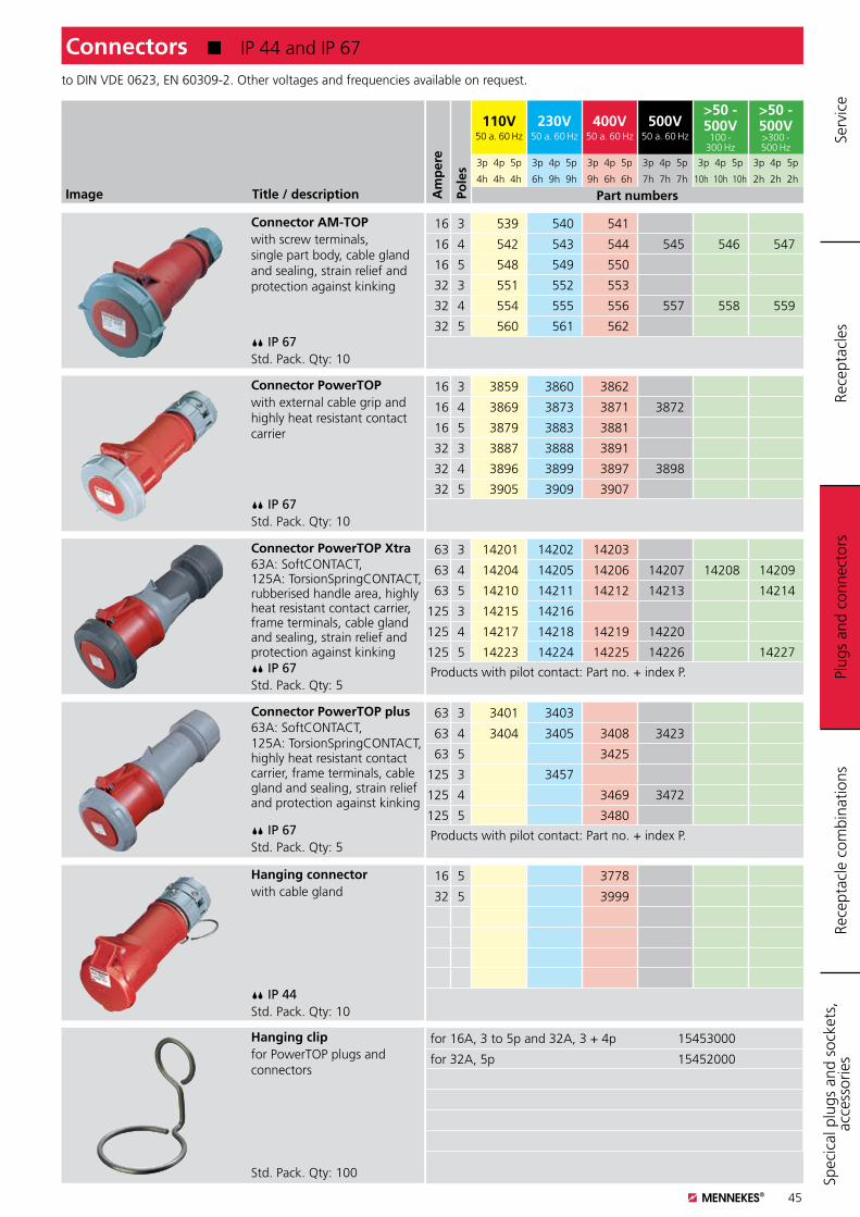
45
Image Title / description
Connector AM-TOP with screw terminals, single part body, cable gland and sealing, strain relief and protection against kinking
IP 67Std. Pack. Qty: 10
Connector PowerTOP with external cable grip and highly heat resistant contact carrier
IP 67Std. Pack. Qty: 10
Connector PowerTOP Xtra 63A: SoftCONTACT, 125A: TorsionSpringCONTACT, rubberised handle area, highly heat resistant contact carrier, frame terminals, cable gland and sealing, strain relief and protection against kinking IP 67Std. Pack. Qty: 5
Hanging clipfor PowerTOP plugs and connectors
Std. Pack. Qty: 100
to DIN VDE 0623, EN 60309-2. Other voltages and frequencies available on request.
16 3 539 540 541
16 4 542 543 544 545 546 547
16 5 548 549 550
32 3 551 552 553
32 4 554 555 556 557 558 559
32 5 560 561 562
16 3 3859 3860 3862
16 4 3869 3873 3871 3872
16 5 3879 3883 3881
32 3 3887 3888 3891
32 4 3896 3899 3897 3898
32 5 3905 3909 3907
63 3 14201 14202 14203
63 4 14204 14205 14206 14207 14208 14209
63 5 14210 14211 14212 14213 14214
125 3 14215 14216
125 4 14217 14218 14219 14220
125 5 14223 14224 14225 14226 14227
Products with pilot contact: Part no. + index P.
for 16A, 3 to 5p and 32A, 3 + 4p 15453000
for 32A, 5p 15452000
Connectors K IP 44 and IP 67
Hanging connector with cable gland
IP 44Std. Pack. Qty: 10
16 5 3778
32 5 3999
Connector PowerTOP plus 63A: SoftCONTACT, 125A: TorsionSpringCONTACT, highly heat resistant contact carrier, frame terminals, cable gland and sealing, strain relief and protection against kinking
IP 67Std. Pack. Qty: 5
63 3 3401 3403
63 4 3404 3405 3408 3423
63 5 3425
125 3 3457
125 4 3469 3472
125 5 3480
Products with pilot contact: Part no. + index P.Pl
ugs
and
conn
ecto
rsRe
cept
acle
sRe
cept
acle
com
bina
tions
Spec
ical
plu
gs a
nd s
ocke
ts,
acce
ssor
ies
Serv
ice
Am
per
e
Pole
s
110V50 a. 60 Hz
230V50 a. 60 Hz
400V50 a. 60 Hz
500V50 a. 60 Hz
>50 - 500V
100 - 300 Hz
>50 - 500V>300 - 500 Hz
3p 4p 5p 3p 4p 5p 3p 4p 5p 3p 4p 5p 3p 4p 5p 3p 4p 5p
4h 4h 4h 6h 9h 9h 9h 6h 6h 7h 7h 7h 10h 10h 10h 2h 2h 2h
Part numbers
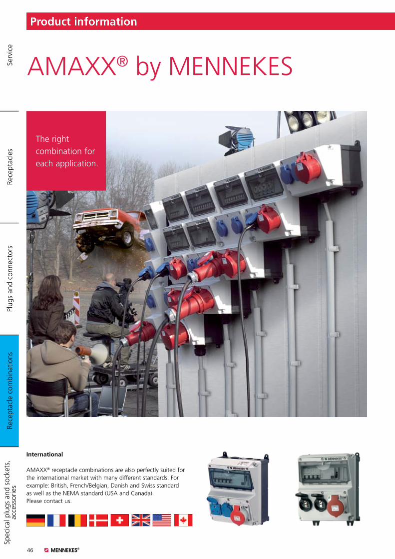
46
Product information
International
AMAXX® receptacle combinations are also perfectly suited for the international market with many different standards. For example: British, French/Belgian, Danish and Swiss standard as well as the NEMA standard (USA and Canada). Please contact us.
The right combination for each application.
AMAXX® by MENNEKES
Rece
ptac
le c
ombi
natio
nsPl
ugs
and
conn
ecto
rsRe
cept
acle
sSp
ecic
al p
lugs
and
soc
kets
, ac
cess
orie
s Se
rvic
e
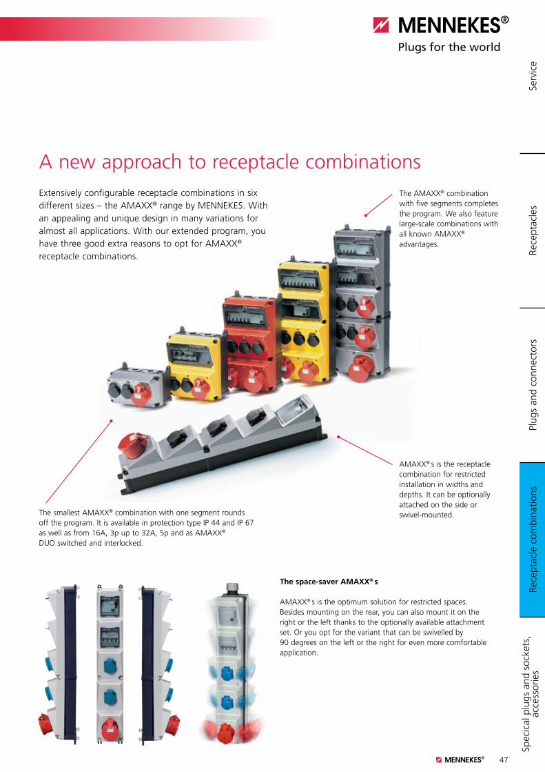
47
A new approach to receptacle combinations
The space-saver AMAXX® s AMAXX® s is the optimum solution for restricted spaces. Besides mounting on the rear, you can also mount it on the right or the left thanks to the optionally available attachment set. Or you opt for the variant that can be swivelled by 90 degrees on the left or the right for even more comfortable application.
The AMAXX® combination with five segments completes the program. We also feature large-scale combinations with all known AMAXX® advantages.
AMAXX® s is the receptacle combination for restricted installation in widths and depths. It can be optionally attached on the side or swivel-mounted.The smallest AMAXX® combination with one segment rounds
off the program. It is available in protection type IP 44 and IP 67 as well as from 16A, 3p up to 32A, 5p and as AMAXX® DUO switched and interlocked.
Extensively configurable receptacle combinations in six different sizes – the AMAXX® range by MENNEKES. With an appealing and unique design in many variations for almost all applications. With our extended program, you have three good extra reasons to opt for AMAXX® receptacle combinations.
Product information
Rece
ptac
le c
ombi
natio
nsPl
ugs
and
conn
ecto
rsRe
cept
acle
sSp
ecic
al p
lugs
and
soc
kets
, ac
cess
orie
s Se
rvic
e
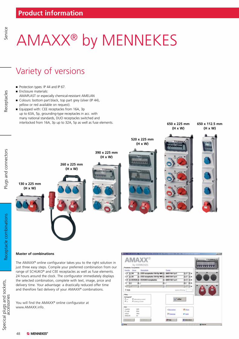
48
Product information
AMAXX® by MENNEKES
Variety of versions
Master of combinations The AMAXX® online configurator takes you to the right solution in just three easy steps. Compile your preferred combination from our range of SCHUKO® and CEE receptacles as well as fuse elements. 24 hours around the clock. The configurator immediately displays the selected combination, complete with text, image, price and delivery time. Your advantage: a drastically reduced offer time and therefore fast delivery of your AMAXX® combinations.
You will find the AMAXX® online configurator at www.AMAXX.info.
K Protection types: IP 44 and IP 67. K Enclosure materials: AMAPLAST or especially chemical-resistant AMELAN K Colours: bottom part black, top part grey (silver (IP 44), yellow or red available on request). K Equipped with: CEE receptacles from 16A, 3p up to 63A, 5p, grounding-type receptacles in acc. with many national standards, DUO receptacles switched and interlocked from 16A, 3p up to 32A, 5p as well as fuse elements.
130 x 225 mm (H x W)
260 x 225 mm (H x W)
390 x 225 mm (H x W)
520 x 225 mm (H x W)
650 x 225 mm (H x W)
650 x 112.5 mm (H x W)
Rece
ptac
le c
ombi
natio
nsPl
ugs
and
conn
ecto
rsRe
cept
acle
sSp
ecic
al p
lugs
and
soc
kets
, ac
cess
orie
s Se
rvic
e
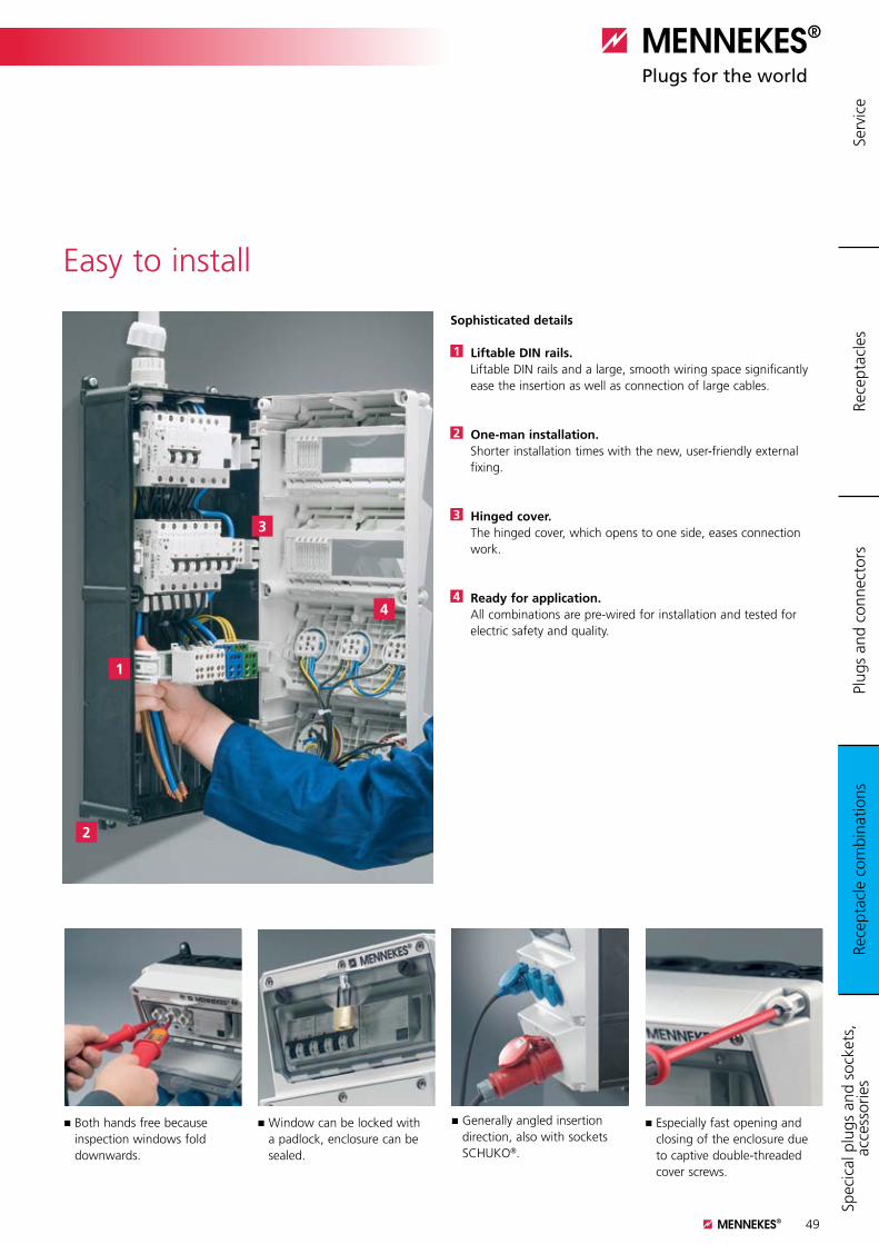
49
Sophisticated details
1 Liftable DIN rails. Liftable DIN rails and a large, smooth wiring space significantly ease the insertion as well as connection of large cables.
2 One-man installation. Shorter installation times with the new, user-friendly external fixing.
3 Hinged cover. The hinged cover, which opens to one side, eases connection work.
4 Ready for application.All combinations are pre-wired for installation and tested for electric safety and quality.
1
2
3
4
Easy to install
Product information
Rece
ptac
le c
ombi
natio
nsPl
ugs
and
conn
ecto
rsRe
cept
acle
sSp
ecic
al p
lugs
and
soc
kets
, ac
cess
orie
s Se
rvic
e
K Both hands free because inspection windows fold downwards.
K Window can be locked with a padlock, enclosure can be sealed.
K Generally angled insertion direction, also with sockets SCHUKO®.
K Especially fast opening and closing of the enclosure due to captive double-threaded cover screws.
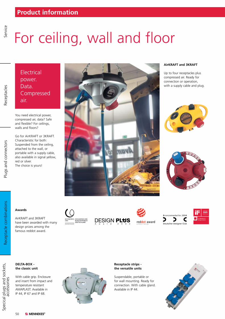
50
Product information
Electrical power. Data. Compressed air.
For ceiling, wall and floor
You need electrical power, compressed air, data? Safe and flexible? For ceilings, walls and floors?
Go for AirKRAFT or 3KRAFT. Characteristic for both: Suspended from the ceiling, attached to the wall, or portable with a supply cable, also available in signal yellow, red or silver. The choice is yours!
AirKRAFT and 3KRAFT Up to four receptacles plus compressed air. Ready for connection or operation, with a supply cable and plug.
Awards
AirKRAFT and 3KRAFT have been awarded with many design prizes among the famous reddot award.
Receptacle strips - the versatile units Suspendable, portable or for wall mounting. Ready for connection. With cable gland. Available in IP 44.
DELTA-BOX - the classic unit
With cable grip. Enclosure and insert from impact and temperature resistant AMAPLAST. Available in IP 44, IP 67 and IP 68.
Rece
ptac
le c
ombi
natio
nsPl
ugs
and
conn
ecto
rsRe
cept
acle
sSp
ecic
al p
lugs
and
soc
kets
, ac
cess
orie
s Se
rvic
e

51
EverGUM - solid rubber receptacle combinations
Especially when there is likely to be exposure to rough handling or aggressive cleaning agents.
K Resistant to weather and ageing.K High dimensional stability and precision.K Good resistance to acids and alkalis. K High dieletric strength and creep resistance.
Safe. Robust. Versatile.
Solid rubber and stainless steel
Stainless steel MENNEKES stainless steel products are made from high grade stainless V2A steel (material 1.4301). Wherever dependable protection against unauthorised access is required. MENNEKES stainless steel combinations are the equipment of choice.
K Wind and weatherproof. K Attractive design. K Easy and swiftly installed.K Durable. K Surface or flush mounted.
Solid rubber receptacle combinations, portable
The all-round power-packages for mobile use in industry, craft and trade. They can accept quite a knock – neither their shape nor their function will be impaired. Additional benefit: they are stackable which allows space-saving storage.
Product information
Rece
ptac
le c
ombi
natio
nsPl
ugs
and
conn
ecto
rsRe
cept
acle
sSp
ecic
al p
lugs
and
soc
kets
, ac
cess
orie
s Se
rvic
e
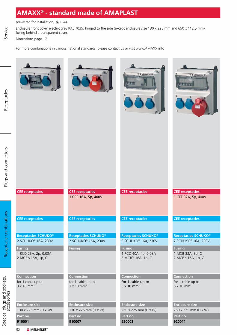
52
pre-wired for installation, IP 44
Enclosure front cover electric grey RAL 7035, hinged to the side (except enclosure size 130 x 225 mm and 650 x 112.5 mm), fusing behind a transparent cover.
Dimensions page 17.
For more combinations in various national standards, please contact us or visit www.AMAXX.info
AMAXX® - standard made of AMAPLAST
CEE receptacles1 CEE 32A, 5p, 400V
CEE receptacles
Receptacles SCHUKO®
2 SCHUKO® 16A, 230V
Fusing1 MCB 32A, 3p, C 2 MCB´s 16A, 1p, C
Connectionfor 1 cable up to 5 x 10 mm2
Enclosure size260 x 225 mm (H x W)
Part no.
920011
CEE receptacles
CEE receptacles
Receptacles SCHUKO®
3 SCHUKO® 16A, 230V
Fusing1 RCD 40A, 4p, 0.03A 3 MCB´s 16A, 1p, C
Connectionfor 1 cable up to 5 x 10 mm2
Enclosure size260 x 225 mm (H x W)
Part no.
920003
CEE receptacles1 CEE 16A, 5p, 400V
CEE receptacles
Receptacles SCHUKO®
2 SCHUKO® 16A, 230V
Fusing
Connectionfor 1 cable up to 3 x 10 mm2
Enclosure size130 x 225 mm (H x W)
Part no.
910007
CEE receptacles
CEE receptacles
Receptacles SCHUKO®
2 SCHUKO® 16A, 230V
Fusing1 RCD 25A, 2p, 0.03A 2 MCB´s 16A, 1p, C
Connectionfor 1 cable up to 3 x 10 mm2
Enclosure size130 x 225 mm (H x W)
Part no.
910001
Rece
ptac
le c
ombi
natio
nsPl
ugs
and
conn
ecto
rsRe
cept
acle
sSp
ecic
al p
lugs
and
soc
kets
, ac
cess
orie
s Se
rvic
e
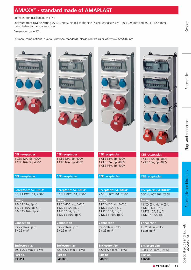
53
pre-wired for installation, IP 44
Enclosure front cover electric grey RAL 7035, hinged to the side (except enclosure size 130 x 225 mm and 650 x 112.5 mm), fusing behind a transparent cover.
Dimensions page 17.
For more combinations in various national standards, please contact us or visit www.AMAXX.info
AMAXX® - standard made of AMAPLAST
CEE receptacles1 CEE 63A, 5p, 400V 1 CEE 32A, 5p, 400V 1 CEE 16A, 5p, 400V
CEE receptacles
Receptacles SCHUKO®
2 SCHUKO® 16A, 230V
Fusing1 RCD 63A, 4p, 0.03A 1 MCB 32A, 3p, C 1 MCB 16A, 3p, C 2 MCB´s 16A, 1p, C
Connectionfor 2 cables up to 5 x 25 mm2
Enclosure size520 x 225 mm (H x W)
Part no.
940010
CEE receptacles1 CEE 32A, 5p, 400V 1 CEE 16A, 5p, 400V
CEE receptacles
Receptacles SCHUKO®
3 SCHUKO® 16A, 230V
Fusing1 RCD 40A, 4p, 0.03A 1 MCB 32A, 3p, C 1 MCB 16A, 3p, C 3 MCB´s 16A, 1p, C
Connectionfor 2 cables up to 5 x 25 mm2
Enclosure size520 x 225 mm (H x W)
Part no.
940005
CEE receptacles1 CEE 32A, 5p, 400V1 CEE 16A, 5p, 400V
CEE receptacles
Receptacles SCHUKO®
3 SCHUKO® 16A, 230V
Fusing1 MCB 32A, 3p, C 1 MCB 16A, 3p, C 3 MCB´s 16A, 1p, C
Connectionfor 2 cables up to 5 x 25 mm2
Enclosure size390 x 225 mm (H x W)
Part no.
930011
CEE receptacles1 CEE 32A, 5p, 400V 1 CEE 16A, 5p, 400V
CEE receptacles
Receptacles SCHUKO®
6 SCHUKO® 16A, 230V
Fusing1 RCD 63A, 4p, 0.03A 1 MCB 32A, 3p, C 1 MCB 16A, 3p, C 6 MCB´s 16A, 1p, C
Connectionfor 2 cables up to 5 x 25 mm2
Enclosure size650 x 225 mm (H x W)
Part no.
950004
Rece
ptac
le c
ombi
natio
nsPl
ugs
and
conn
ecto
rsRe
cept
acle
sSp
ecic
al p
lugs
and
soc
kets
, ac
cess
orie
s Se
rvic
e
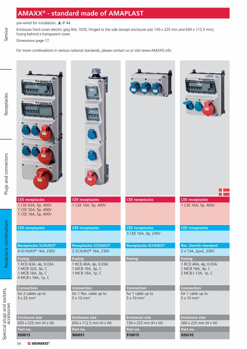
54
pre-wired for installation, IP 44
Enclosure front cover electric grey RAL 7035, hinged to the side (except enclosure size 130 x 225 mm and 650 x 112.5 mm), fusing behind a transparent cover.
Dimensions page 17.
For more combinations in various national standards, please contact us or visit www.AMAXX.info
AMAXX® - standard made of AMAPLAST
CEE receptacles1 CEE 16A, 5p, 400V
CEE receptacles
Rec. Danish standard2 x 13A, 2p+E, 230V
Fusing1 RCD 40A, 4p, 0.03A1 MCB 16A, 3p, C2 MCB´s 13A, 1p, C
Connectionfor 1 cable up to 5 x 10 mm2
Enclosure size260 x 225 mm (H x W)
Part no.
920210
CEE receptacles
CEE receptacles3 CEE 16A, 3p, 230V
Receptacles SCHUKO®
Fusing
Connectionfor 1 cable up to 5 x 10 mm2
Enclosure size130 x 225 mm (H x W)
Part no.
910015
CEE receptacles1 CEE 16A, 5p, 400V
CEE receptacles
Receptacles SCHUKO®
2 SCHUKO® 16A, 230V
Fusing1 RCD 40A, 4p, 0.03A1 MCB 16A, 3p, C1 MCB 16A, 1p, C
Connectionfor 1 flex. cable up to 5 x 10 mm2
Enclosure size650 x 112.5 mm (H x W)
Part no.
960051
CEE receptacles1 CEE 63A, 5p, 400V1 CEE 32A, 5p, 400V1 CEE 16A, 5p, 400V
CEE receptacles
Receptacles SCHUKO®
4 SCHUKO® 16A, 230V
Fusing1 RCD 63A, 4p, 0.03A1 MCB 32A, 3p, C1 MCB 16A, 3p, C4 MCB´s 16A, 1p, C
Connectionfor 2 cables up to 5 x 25 mm2
Enclosure size650 x 225 mm (H x W)
Part no.
950013
Rece
ptac
le c
ombi
natio
nsPl
ugs
and
conn
ecto
rsRe
cept
acle
sSp
ecic
al p
lugs
and
soc
kets
, ac
cess
orie
s Se
rvic
e
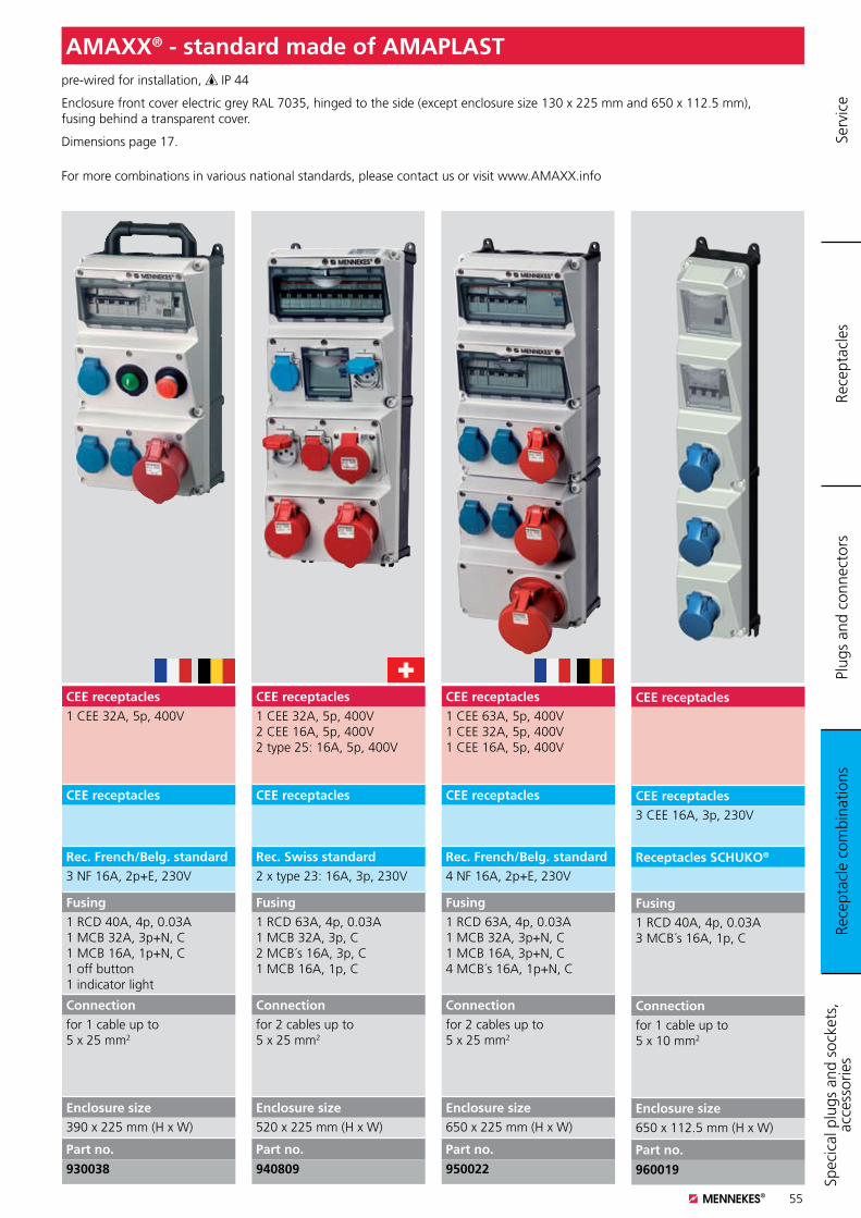
55
pre-wired for installation, IP 44
Enclosure front cover electric grey RAL 7035, hinged to the side (except enclosure size 130 x 225 mm and 650 x 112.5 mm), fusing behind a transparent cover.
Dimensions page 17.
For more combinations in various national standards, please contact us or visit www.AMAXX.info
AMAXX® - standard made of AMAPLAST
CEE receptacles1 CEE 63A, 5p, 400V 1 CEE 32A, 5p, 400V 1 CEE 16A, 5p, 400V
CEE receptacles
Rec. French/Belg. standard4 NF 16A, 2p+E, 230V
Fusing1 RCD 63A, 4p, 0.03A1 MCB 32A, 3p+N, C1 MCB 16A, 3p+N, C4 MCB´s 16A, 1p+N, C
Connectionfor 2 cables up to 5 x 25 mm2
Enclosure size650 x 225 mm (H x W)
Part no.
950022
CEE receptacles1 CEE 32A, 5p, 400V2 CEE 16A, 5p, 400V2 type 25: 16A, 5p, 400V
CEE receptacles
Rec. Swiss standard2 x type 23: 16A, 3p, 230V
Fusing1 RCD 63A, 4p, 0.03A1 MCB 32A, 3p, C2 MCB´s 16A, 3p, C1 MCB 16A, 1p, C
Connectionfor 2 cables up to 5 x 25 mm2
Enclosure size520 x 225 mm (H x W)
Part no.
940809
CEE receptacles1 CEE 32A, 5p, 400V
CEE receptacles
Rec. French/Belg. standard3 NF 16A, 2p+E, 230V
Fusing1 RCD 40A, 4p, 0.03A1 MCB 32A, 3p+N, C1 MCB 16A, 1p+N, C1 off button1 indicator light
Connectionfor 1 cable up to 5 x 25 mm2
Enclosure size390 x 225 mm (H x W)
Part no.
930038
CEE receptacles
CEE receptacles3 CEE 16A, 3p, 230V
Receptacles SCHUKO®
Fusing1 RCD 40A, 4p, 0.03A3 MCB´s 16A, 1p, C
Connectionfor 1 cable up to 5 x 10 mm2
Enclosure size650 x 112.5 mm (H x W)
Part no.
960019
Rece
ptac
le c
ombi
natio
nsPl
ugs
and
conn
ecto
rsRe
cept
acle
sSp
ecic
al p
lugs
and
soc
kets
, ac
cess
orie
s Se
rvic
e
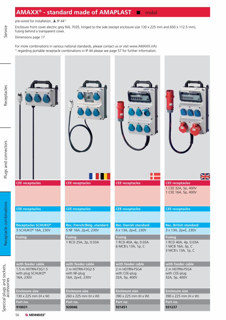
56
pre-wired for installation, IP 44 1)
Enclosure front cover electric grey RAL 7035, hinged to the side (except enclosure size 130 x 225 mm and 650 x 112.5 mm), fusing behind a transparent cover.
Dimensions page 17.
For more combinations in various national standards, please contact us or visit www.AMAXX.info1) regarding portable receptacle combinations in IP 44 please see page 57 for further information.
AMAXX® - standard made of AMAPLAST K mobil
CEE receptacles1 CEE 32A, 5p, 400V1 CEE 16A, 5p, 400V
CEE receptacles
Rec. British standard3 x 13A, 2p+E, 230V
Fusing1 RCD 40A, 4p, 0.03A1 MCB 16A, 3p, C3 MCB´s 13A, 1p, C
with feeder cable2 m H07RN-F5G4with CEE-plug 32A, 5p, 400V
Enclosure size390 x 225 mm (H x W)
Part no.
931237
CEE receptacles
CEE receptacles
Rec. Danish standard6 x 13A, 2p+E, 230V
Fusing1 RCD 40A, 4p, 0.03A6 MCB´s 13A, 1p, C
with feeder cable2 m H07RN-F5G4with CEE-plug 32A, 5p, 400V
Enclosure size390 x 225 mm (H x W)
Part no.
931451
CEE receptacles
CEE receptacles
Rec. French/Belg. standard5 NF 16A, 2p+E, 230V
Fusing1 RCD 25A, 2p, 0.03A
with feeder cable2 m H07RN-F3G2.5with NF-plug 16A, 2p+E, 230V
Enclosure size260 x 225 mm (H x W)
Part no.
920046
CEE receptacles
CEE receptacles
Receptacles SCHUKO®
3 SCHUKO® 16A, 230V
Fusing
with feeder cable1.5 m H07RN-F3G1.5with plug SCHUKO® 16A, 230V
Enclosure size130 x 225 mm (H x W)
Part no.
910031
Rece
ptac
le c
ombi
natio
nsPl
ugs
and
conn
ecto
rsRe
cept
acle
sSp
ecic
al p
lugs
and
soc
kets
, ac
cess
orie
s Se
rvic
e
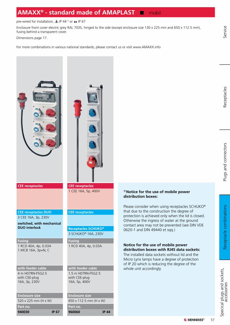
57
pre-wired for installation, IP 44 1) or IP 67
Enclosure front cover electric grey RAL 7035, hinged to the side (except enclosure size 130 x 225 mm and 650 x 112.5 mm), fusing behind a transparent cover.
Dimensions page 17.
For more combinations in various national standards, please contact us or visit www.AMAXX.info
AMAXX® - standard made of AMAPLAST K mobil
CEE receptacles1 CEE 16A, 5p, 400V
CEE receptacles
Receptacles SCHUKO®
3 SCHUKO® 16A, 230V
Fusing1 RCD 40A, 4p, 0.03A
with feeder cable1.5 m H07RN-F5G2.5with CEE-plug 16A, 5p, 400V
Enclosure size650 x 112.5 mm (H x W)
Part no.
960060 IP 44
CEE receptacles
CEE receptacles DUO3 CEE 16A, 3p, 230V
switched, with mechanical DUO interlock
Fusing1 RCD 40A, 4p, 0.03A1 MCB 16A, 3p+N, C
with feeder cable4 m H07RN-F5G2.5 with CEE-plug 16A, 3p, 230V
Enclosure size520 x 225 mm (H x W)
Part no.
940030 IP 67
1) Notice for the use of mobile power distribution boxes:
Please consider when using receptacles SCHUKO® that due to the construction the degree of protection is achieved only when the lid is closed. Otherwise the ingress of water at the ground contact area may not be prevented (see DIN VDE 0620-1 and DIN 49440 et sqq.)
Notice for the use of mobile power distribution boxes with RJ45 data sockets:The installed data sockets without lid and the Micro Lynx lamps have a degree of protection of IP 20 which is reducing the degree of the whole unit accordingly.
Rece
ptac
le c
ombi
natio
nsPl
ugs
and
conn
ecto
rsRe
cept
acle
sSp
ecic
al p
lugs
and
soc
kets
, ac
cess
orie
s Se
rvic
e
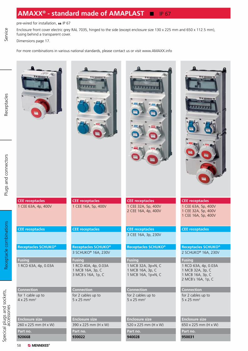
58
pre-wired for installation, IP 67
Enclosure front cover electric grey RAL 7035, hinged to the side (except enclosure size 130 x 225 mm and 650 x 112.5 mm), fusing behind a transparent cover.
Dimensions page 17.
For more combinations in various national standards, please contact us or visit www.AMAXX.info
AMAXX® - standard made of AMAPLAST K IP 67
CEE receptacles1 CEE 63A, 5p, 400V1 CEE 32A, 5p, 400V1 CEE 16A, 5p, 400V
CEE receptacles
Receptacles SCHUKO®
2 SCHUKO® 16A, 230V
Fusing1 RCD 63A, 4p, 0.03A1 MCB 32A, 3p, C1 MCB 16A, 3p, C2 MCB´s 16A, 1p, C
Connectionfor 2 cables up to 5 x 25 mm2
Enclosure size650 x 225 mm (H x W)
Part no.
950031
CEE receptacles1 CEE 32A, 5p, 400V2 CEE 16A, 4p, 400V
CEE receptacles3 CEE 16A, 3p, 230V
Receptacles SCHUKO®
Fusing1 MCB 32A, 3p+N, C1 MCB 16A, 3p, C1 MCB 16A, 1p+N, C
Connectionfor 2 cables up to 5 x 25 mm2
Enclosure size520 x 225 mm (H x W)
Part no.
940028
CEE receptacles1 CEE 16A, 5p, 400V
CEE receptacles
Receptacles SCHUKO®
3 SCHUKO® 16A, 230V
Fusing1 RCD 40A, 4p, 0.03A1 MCB 16A, 3p, C3 MCB´s 16A, 1p, C
Connectionfor 2 cables up to 5 x 25 mm2
Enclosure size390 x 225 mm (H x W)
Part no.
930022
CEE receptacles1 CEE 63A, 4p, 400V
CEE receptacles
Receptacles SCHUKO®
Fusing1 RCD 63A, 4p, 0.03A
Connectionfor 1 cable up to 4 x 25 mm2
Enclosure size260 x 225 mm (H x W)
Part no.
920668
Rece
ptac
le c
ombi
natio
nsPl
ugs
and
conn
ecto
rsRe
cept
acle
sSp
ecic
al p
lugs
and
soc
kets
, ac
cess
orie
s Se
rvic
e
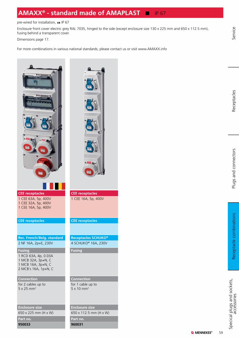
59
pre-wired for installation, IP 67
Enclosure front cover electric grey RAL 7035, hinged to the side (except enclosure size 130 x 225 mm and 650 x 112.5 mm), fusing behind a transparent cover.
Dimensions page 17.
For more combinations in various national standards, please contact us or visit www.AMAXX.info
AMAXX® - standard made of AMAPLAST K IP 67
CEE receptacles1 CEE 16A, 5p, 400V
CEE receptacles
Receptacles SCHUKO®
4 SCHUKO® 16A, 230V
Fusing
Connectionfor 1 cable up to 5 x 10 mm2
Enclosure size650 x 112.5 mm (H x W)
Part no.
960031
CEE receptacles1 CEE 63A, 5p, 400V1 CEE 32A, 5p, 400V1 CEE 16A, 5p, 400V
CEE receptacles
Rec. French/Belg. standard2 NF 16A, 2p+E, 230V
Fusing1 RCD 63A, 4p, 0.03A1 MCB 32A, 3p+N, C1 MCB 16A, 3p+N, C2 MCB´s 16A, 1p+N, C
Connectionfor 2 cables up to 5 x 25 mm2
Enclosure size650 x 225 mm (H x W)
Part no.
950033
Rece
ptac
le c
ombi
natio
nsPl
ugs
and
conn
ecto
rsRe
cept
acle
sSp
ecic
al p
lugs
and
soc
kets
, ac
cess
orie
s Se
rvic
e
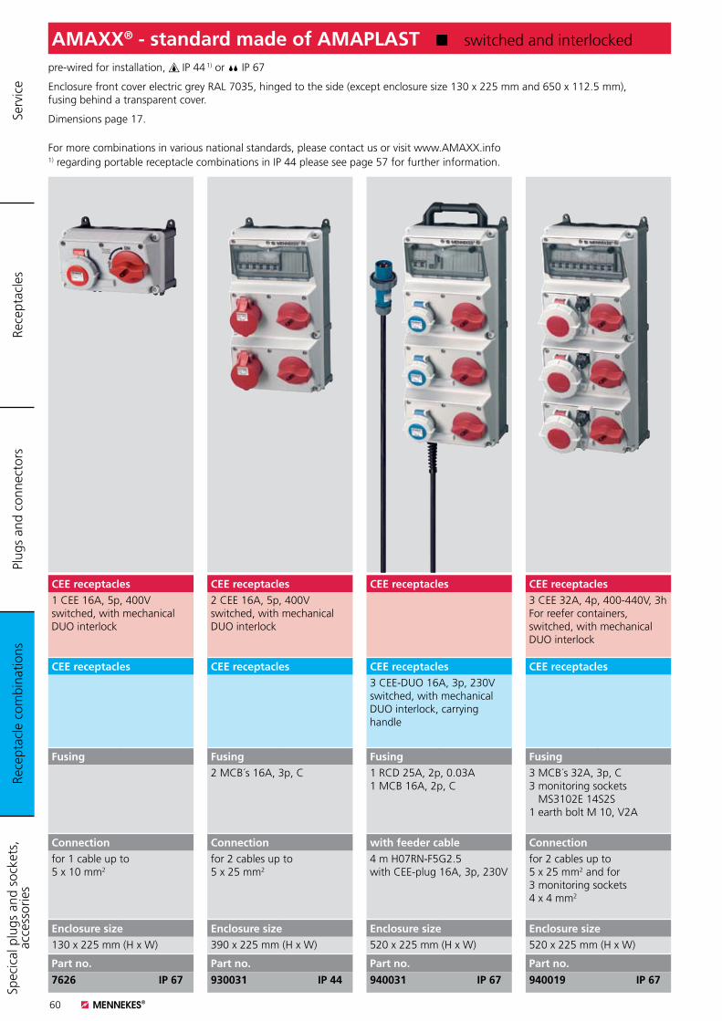
60
pre-wired for installation, IP 44 1) or IP 67
Enclosure front cover electric grey RAL 7035, hinged to the side (except enclosure size 130 x 225 mm and 650 x 112.5 mm), fusing behind a transparent cover.
Dimensions page 17.
For more combinations in various national standards, please contact us or visit www.AMAXX.info1) regarding portable receptacle combinations in IP 44 please see page 57 for further information.
AMAXX® - standard made of AMAPLAST K switched and interlocked
CEE receptacles3 CEE 32A, 4p, 400-440V, 3hFor reefer containers,switched, with mechanical DUO interlock
CEE receptacles
Fusing3 MCB´s 32A, 3p, C3 monitoring sockets MS3102E 14S2S1 earth bolt M 10, V2A
Connectionfor 2 cables up to 5 x 25 mm2 and for 3 monitoring sockets 4 x 4 mm2
Enclosure size520 x 225 mm (H x W)
Part no.
940019 IP 67
CEE receptacles
CEE receptacles3 CEE-DUO 16A, 3p, 230V switched, with mechanical DUO interlock, carrying handle
Fusing1 RCD 25A, 2p, 0.03A1 MCB 16A, 2p, C
with feeder cable4 m H07RN-F5G2.5with CEE-plug 16A, 3p, 230V
Enclosure size520 x 225 mm (H x W)
Part no.
940031 IP 67
CEE receptacles2 CEE 16A, 5p, 400Vswitched, with mechanical DUO interlock
CEE receptacles
Fusing2 MCB´s 16A, 3p, C
Connectionfor 2 cables up to 5 x 25 mm2
Enclosure size390 x 225 mm (H x W)
Part no.
930031 IP 44
CEE receptacles1 CEE 16A, 5p, 400Vswitched, with mechanical DUO interlock
CEE receptacles
Fusing
Connectionfor 1 cable up to 5 x 10 mm2
Enclosure size130 x 225 mm (H x W)
Part no.
7626 IP 67
Rece
ptac
le c
ombi
natio
nsPl
ugs
and
conn
ecto
rsRe
cept
acle
sSp
ecic
al p
lugs
and
soc
kets
, ac
cess
orie
s Se
rvic
e
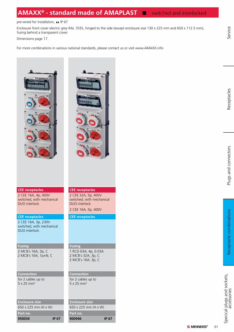
61
pre-wired for installation, IP 67
Enclosure front cover electric grey RAL 7035, hinged to the side (except enclosure size 130 x 225 mm and 650 x 112.5 mm), fusing behind a transparent cover.
Dimensions page 17.
For more combinations in various national standards, please contact us or visit www.AMAXX.info
AMAXX® - standard made of AMAPLAST K switched and interlocked
CEE receptacles2 CEE 32A, 5p, 400Vswitched, with mechanical DUO interlock
2 CEE 16A, 5p, 400V
CEE receptacles
Fusing1 RCD 63A, 4p, 0.03A2 MCB´s 32A, 3p, C2 MCB´s 16A, 3p, C
Connectionfor 2 cables up to 5 x 25 mm2
Enclosure size650 x 225 mm (H x W)
Part no.
900946 IP 67
CEE receptacles2 CEE 16A, 4p, 400Vswitched, with mechanical DUO interlock
CEE receptacles2 CEE 16A, 3p, 230Vswitched, with mechanical DUO interlock
Fusing2 MCB´s 16A, 3p, C2 MCB´s 16A, 1p+N, C
Connectionfor 2 cables up to 5 x 25 mm2
Enclosure size650 x 225 mm (H x W)
Part no.
950034 IP 67
Rece
ptac
le c
ombi
natio
nsPl
ugs
and
conn
ecto
rsRe
cept
acle
sSp
ecic
al p
lugs
and
soc
kets
, ac
cess
orie
s Se
rvic
e
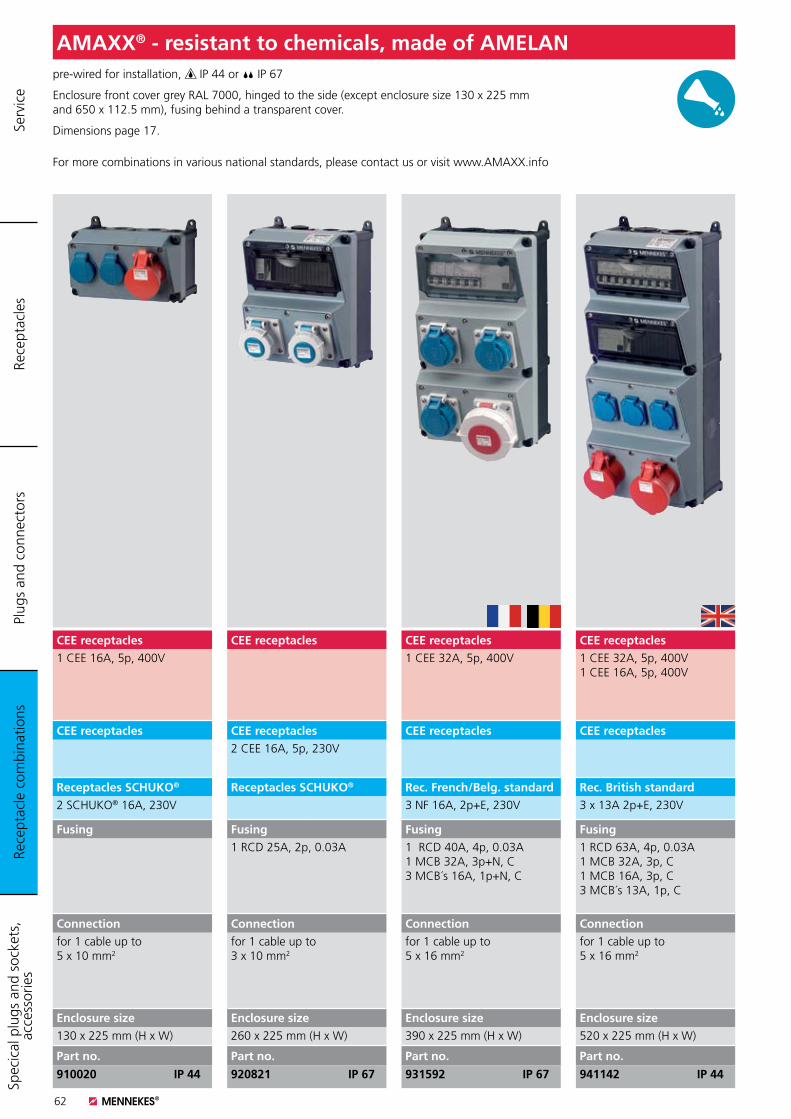
62
pre-wired for installation, IP 44 or IP 67
Enclosure front cover grey RAL 7000, hinged to the side (except enclosure size 130 x 225 mm and 650 x 112.5 mm), fusing behind a transparent cover.
Dimensions page 17.
For more combinations in various national standards, please contact us or visit www.AMAXX.info
AMAXX® - resistant to chemicals, made of AMELAN
CEE receptacles1 CEE 32A, 5p, 400V1 CEE 16A, 5p, 400V
CEE receptacles
Rec. British standard3 x 13A 2p+E, 230V
Fusing1 RCD 63A, 4p, 0.03A1 MCB 32A, 3p, C1 MCB 16A, 3p, C3 MCB´s 13A, 1p, C
Connectionfor 1 cable up to 5 x 16 mm2
Enclosure size520 x 225 mm (H x W)
Part no.
941142 IP 44
CEE receptacles1 CEE 32A, 5p, 400V
CEE receptacles
Rec. French/Belg. standard3 NF 16A, 2p+E, 230V
Fusing1 RCD 40A, 4p, 0.03A1 MCB 32A, 3p+N, C3 MCB´s 16A, 1p+N, C
Connectionfor 1 cable up to 5 x 16 mm2
Enclosure size390 x 225 mm (H x W)
Part no.
931592 IP 67
CEE receptacles
CEE receptacles2 CEE 16A, 5p, 230V
Receptacles SCHUKO®
Fusing1 RCD 25A, 2p, 0.03A
Connectionfor 1 cable up to 3 x 10 mm2
Enclosure size260 x 225 mm (H x W)
Part no.
920821 IP 67
CEE receptacles1 CEE 16A, 5p, 400V
CEE receptacles
Receptacles SCHUKO®
2 SCHUKO® 16A, 230V
Fusing
Connectionfor 1 cable up to 5 x 10 mm2
Enclosure size130 x 225 mm (H x W)
Part no.
910020 IP 44
Rece
ptac
le c
ombi
natio
nsPl
ugs
and
conn
ecto
rsRe
cept
acle
sSp
ecic
al p
lugs
and
soc
kets
, ac
cess
orie
s Se
rvic
e
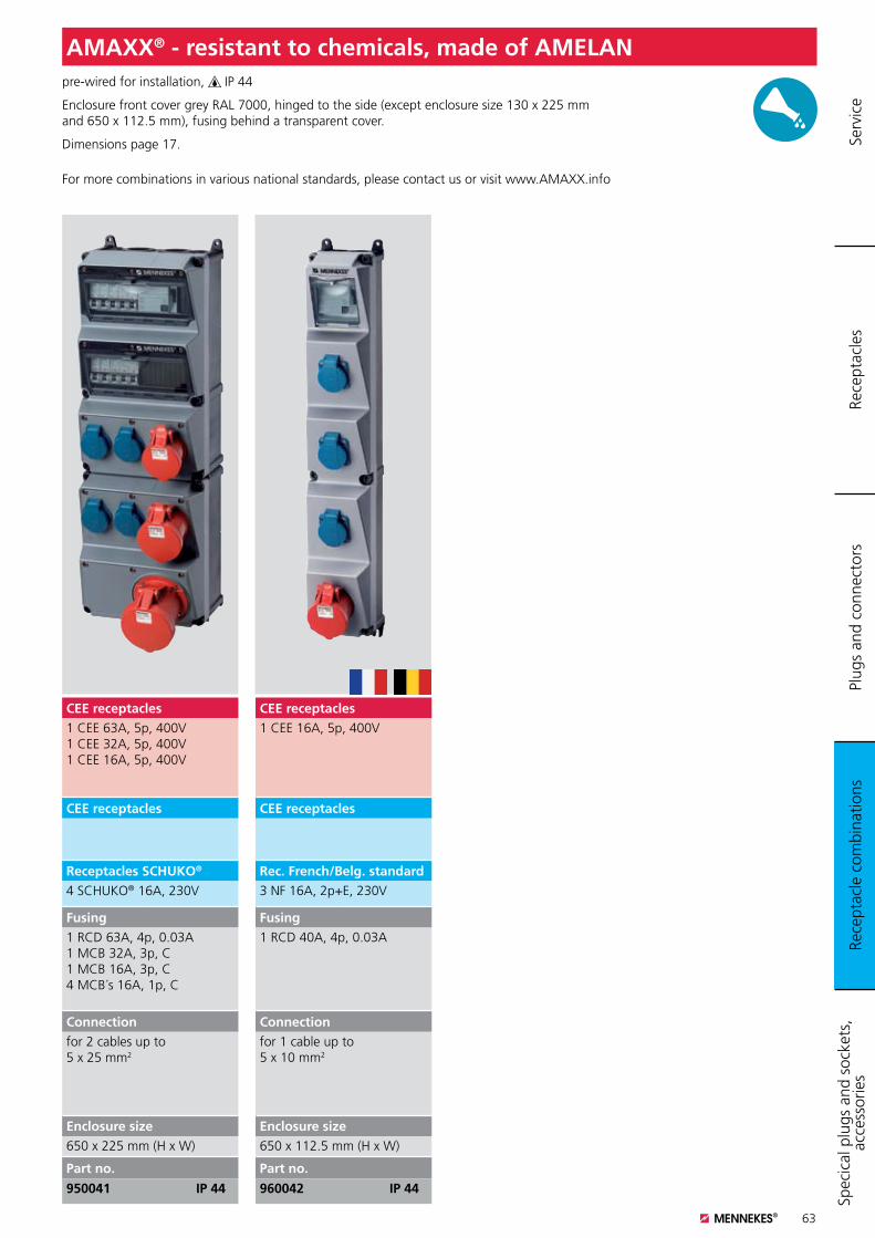
63
pre-wired for installation, IP 44
Enclosure front cover grey RAL 7000, hinged to the side (except enclosure size 130 x 225 mm and 650 x 112.5 mm), fusing behind a transparent cover.
Dimensions page 17.
For more combinations in various national standards, please contact us or visit www.AMAXX.info
AMAXX® - resistant to chemicals, made of AMELAN
CEE receptacles1 CEE 16A, 5p, 400V
CEE receptacles
Rec. French/Belg. standard3 NF 16A, 2p+E, 230V
Fusing1 RCD 40A, 4p, 0.03A
Connectionfor 1 cable up to 5 x 10 mm2
Enclosure size650 x 112.5 mm (H x W)
Part no.
960042 IP 44
CEE receptacles1 CEE 63A, 5p, 400V1 CEE 32A, 5p, 400V1 CEE 16A, 5p, 400V
CEE receptacles
Receptacles SCHUKO®
4 SCHUKO® 16A, 230V
Fusing1 RCD 63A, 4p, 0.03A1 MCB 32A, 3p, C1 MCB 16A, 3p, C4 MCB´s 16A, 1p, C
Connectionfor 2 cables up to 5 x 25 mm2
Enclosure size650 x 225 mm (H x W)
Part no.
950041 IP 44
Rece
ptac
le c
ombi
natio
nsPl
ugs
and
conn
ecto
rsRe
cept
acle
sSp
ecic
al p
lugs
and
soc
kets
, ac
cess
orie
s Se
rvic
e
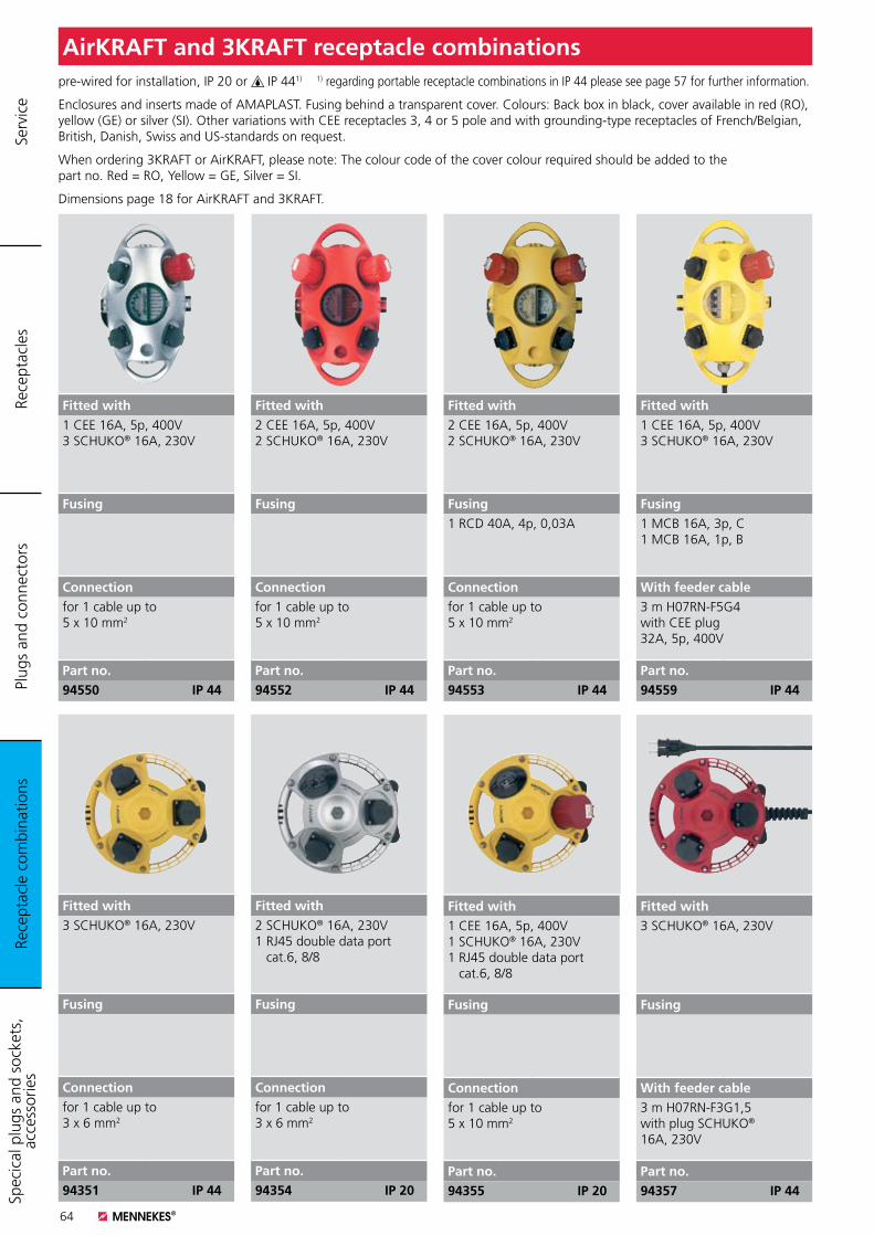
64
pre-wired for installation, IP 20 or IP 441) 1) regarding portable receptacle combinations in IP 44 please see page 57 for further information.
Enclosures and inserts made of AMAPLAST. Fusing behind a transparent cover. Colours: Back box in black, cover available in red (RO), yellow (GE) or silver (SI). Other variations with CEE receptacles 3, 4 or 5 pole and with grounding-type receptacles of French/Belgian, British, Danish, Swiss and US-standards on request.
When ordering 3KRAFT or AirKRAFT, please note: The colour code of the cover colour required should be added to the part no. Red = RO, Yellow = GE, Silver = SI.
Dimensions page 18 for AirKRAFT and 3KRAFT.
AirKRAFT and 3KRAFT receptacle combinations
Fitted with3 SCHUKO® 16A, 230V
Fusing
Connectionfor 1 cable up to3 x 6 mm2
Part no.94351 IP 44
Fitted with2 SCHUKO® 16A, 230V1 RJ45 double data port cat.6, 8/8
Fusing
Connectionfor 1 cable up to3 x 6 mm2
Part no.94354 IP 20
Fitted with1 CEE 16A, 5p, 400V1 SCHUKO® 16A, 230V1 RJ45 double data port cat.6, 8/8
Fusing
Connectionfor 1 cable up to5 x 10 mm2
Part no.94355 IP 20
Fitted with2 CEE 16A, 5p, 400V2 SCHUKO® 16A, 230V
Fusing
Connectionfor 1 cable up to5 x 10 mm2
Part no.94552 IP 44
Fitted with1 CEE 16A, 5p, 400V3 SCHUKO® 16A, 230V
Fusing
Connectionfor 1 cable up to5 x 10 mm2
Part no.94550 IP 44
Fitted with2 CEE 16A, 5p, 400V2 SCHUKO® 16A, 230V
Fusing1 RCD 40A, 4p, 0,03A
Connectionfor 1 cable up to5 x 10 mm2
Part no.94553 IP 44
Fitted with3 SCHUKO® 16A, 230V
Fusing
With feeder cable3 m H07RN-F3G1,5 with plug SCHUKO® 16A, 230V
Part no.94357 IP 44
Fitted with1 CEE 16A, 5p, 400V3 SCHUKO® 16A, 230V
Fusing1 MCB 16A, 3p, C1 MCB 16A, 1p, B
With feeder cable3 m H07RN-F5G4 with CEE plug32A, 5p, 400V
Part no.94559 IP 44
Rece
ptac
le c
ombi
natio
nsPl
ugs
and
conn
ecto
rsRe
cept
acle
sSp
ecic
al p
lugs
and
soc
kets
, ac
cess
orie
s Se
rvic
e
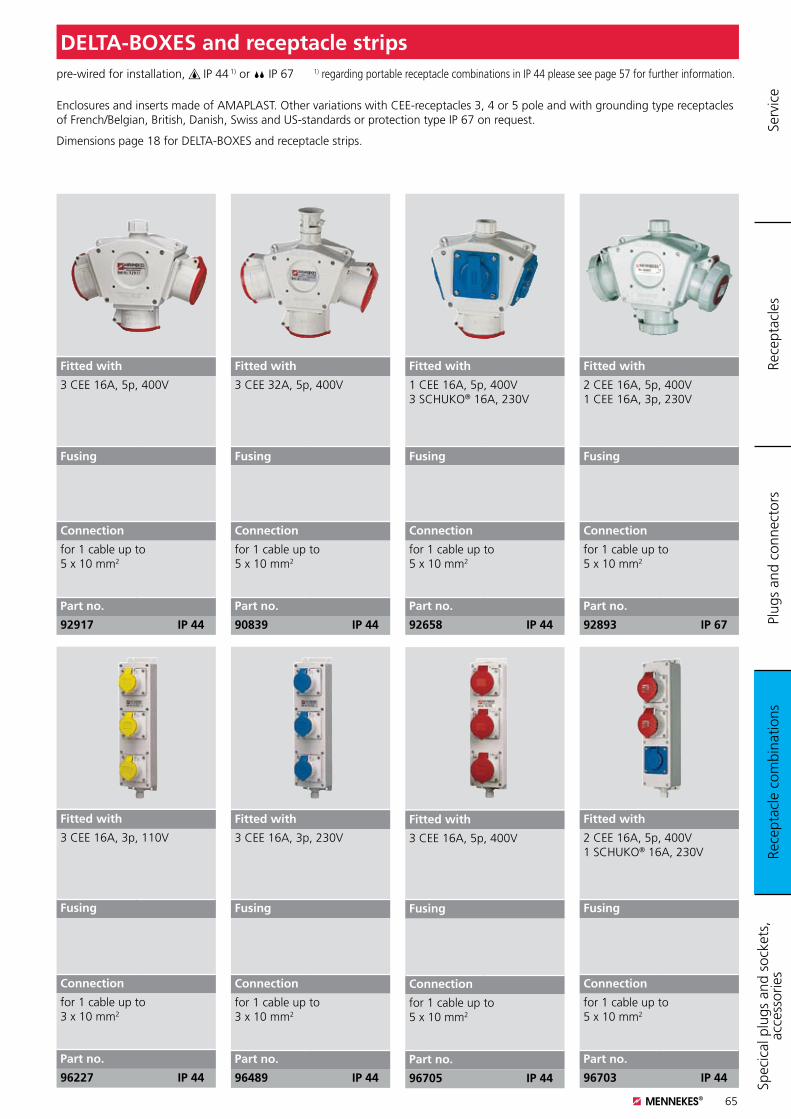
65
pre-wired for installation, IP 44 1) or IP 67 1) regarding portable receptacle combinations in IP 44 please see page 57 for further information.
Enclosures and inserts made of AMAPLAST. Other variations with CEE-receptacles 3, 4 or 5 pole and with grounding type receptacles of French/Belgian, British, Danish, Swiss and US-standards or protection type IP 67 on request.
Dimensions page 18 for DELTA-BOXES and receptacle strips.
DELTA-BOXES and receptacle strips
Fitted with
3 CEE 16A, 5p, 400V
Fusing
Connection
for 1 cable up to5 x 10 mm2
Part no.
96705 IP 44
Fitted with
2 CEE 16A, 5p, 400V1 SCHUKO® 16A, 230V
Fusing
Connection
for 1 cable up to5 x 10 mm2
Part no.
96703 IP 44
Fitted with
2 CEE 16A, 5p, 400V1 CEE 16A, 3p, 230V
Fusing
Connection
for 1 cable up to5 x 10 mm2
Part no.
92893 IP 67
Fitted with
1 CEE 16A, 5p, 400V3 SCHUKO® 16A, 230V
Fusing
Connection
for 1 cable up to5 x 10 mm2
Part no.
92658 IP 44
Fitted with
3 CEE 16A, 5p, 400V
Fusing
Connection
for 1 cable up to5 x 10 mm2
Part no.
92917 IP 44
Fitted with
3 CEE 32A, 5p, 400V
Fusing
Connection
for 1 cable up to5 x 10 mm2
Part no.
90839 IP 44
Fitted with
3 CEE 16A, 3p, 110V
Fusing
Connection
for 1 cable up to3 x 10 mm2
Part no.
96227 IP 44
Fitted with
3 CEE 16A, 3p, 230V
Fusing
Connection
for 1 cable up to3 x 10 mm2
Part no.
96489 IP 44
Rece
ptac
le c
ombi
natio
nsPl
ugs
and
conn
ecto
rsRe
cept
acle
sSp
ecic
al p
lugs
and
soc
kets
, ac
cess
orie
s Se
rvic
e
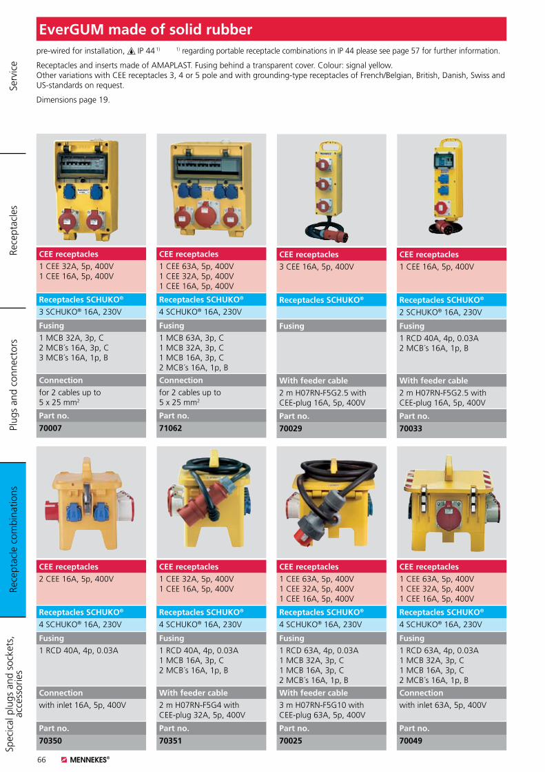
66
pre-wired for installation, IP 44 1) 1) regarding portable receptacle combinations in IP 44 please see page 57 for further information.
Receptacles and inserts made of AMAPLAST. Fusing behind a transparent cover. Colour: signal yellow. Other variations with CEE receptacles 3, 4 or 5 pole and with grounding-type receptacles of French/Belgian, British, Danish, Swiss and US-standards on request.
Dimensions page 19.
EverGUM made of solid rubber
CEE receptacles1 CEE 63A, 5p, 400V1 CEE 32A, 5p, 400V1 CEE 16A, 5p, 400V
Receptacles SCHUKO®
4 SCHUKO® 16A, 230V
Fusing1 RCD 63A, 4p, 0.03A1 MCB 32A, 3p, C1 MCB 16A, 3p, C2 MCB´s 16A, 1p, B
With feeder cable3 m H07RN-F5G10 withCEE-plug 63A, 5p, 400V
Part no.
70025
CEE receptacles2 CEE 16A, 5p, 400V
Receptacles SCHUKO®
4 SCHUKO® 16A, 230V
Fusing1 RCD 40A, 4p, 0.03A
Connectionwith inlet 16A, 5p, 400V
Part no.
70350
CEE receptacles1 CEE 32A, 5p, 400V1 CEE 16A, 5p, 400V
Receptacles SCHUKO®
3 SCHUKO® 16A, 230V
Fusing1 MCB 32A, 3p, C2 MCB´s 16A, 3p, C3 MCB´s 16A, 1p, B
Connectionfor 2 cables up to 5 x 25 mm2
Part no.
70007
CEE receptacles1 CEE 63A, 5p, 400V 1 CEE 32A, 5p, 400V 1 CEE 16A, 5p, 400V
Receptacles SCHUKO®
4 SCHUKO® 16A, 230V
Fusing1 MCB 63A, 3p, C1 MCB 32A, 3p, C1 MCB 16A, 3p, C2 MCB´s 16A, 1p, B
Connectionfor 2 cables up to 5 x 25 mm2
Part no.
71062
CEE receptacles1 CEE 32A, 5p, 400V 1 CEE 16A, 5p, 400V
Receptacles SCHUKO®
4 SCHUKO® 16A, 230V
Fusing1 RCD 40A, 4p, 0.03A1 MCB 16A, 3p, C2 MCB´s 16A, 1p, B
With feeder cable2 m H07RN-F5G4 withCEE-plug 32A, 5p, 400V
Part no.
70351
CEE receptacles1 CEE 63A, 5p, 400V 1 CEE 32A, 5p, 400V 1 CEE 16A, 5p, 400V
Receptacles SCHUKO®
4 SCHUKO® 16A, 230V
Fusing1 RCD 63A, 4p, 0.03A1 MCB 32A, 3p, C1 MCB 16A, 3p, C2 MCB´s 16A, 1p, B
Connectionwith inlet 63A, 5p, 400V
Part no.
70049
CEE receptacles3 CEE 16A, 5p, 400V
Receptacles SCHUKO®
Fusing
With feeder cable2 m H07RN-F5G2.5 withCEE-plug 16A, 5p, 400V
Part no.
70029
CEE receptacles1 CEE 16A, 5p, 400V
Receptacles SCHUKO®
2 SCHUKO® 16A, 230V
Fusing1 RCD 40A, 4p, 0.03A2 MCB´s 16A, 1p, B
With feeder cable2 m H07RN-F5G2.5 withCEE-plug 16A, 5p, 400V
Part no.
70033
Rece
ptac
le c
ombi
natio
nsPl
ugs
and
conn
ecto
rsRe
cept
acle
sSp
ecic
al p
lugs
and
soc
kets
, ac
cess
orie
s Se
rvic
e
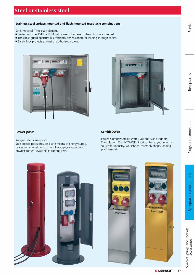
67
Steel or stainless steel
Stainless steel surface mounted and flush mounted receptacle combinations
Safe. Practical. Timelessly elegant. K Protection type IP 43 or IP 44 with closed door, even when plugs are inserted. K The cable guard aperture is sufficiently dimensioned for leading through cables. K Safety lock protects against unauthorised access.
Power posts
Rugged. Vandalism-proof. Steel power posts provide a safe means of energy supply, protection against car-crossing. Hot-dip galvanised and powder coated. Available in various sizes.
CombiTOWER
Power. Compressed air. Water. Outdoors and indoors.The solution: CombiTOWER. Short routes to your energy source for industry, workshops, assembly shops, loading platforms, etc.
Rece
ptac
le c
ombi
natio
nsPl
ugs
and
conn
ecto
rsRe
cept
acle
sSp
ecic
al p
lugs
and
soc
kets
, ac
cess
orie
s Se
rvic
e
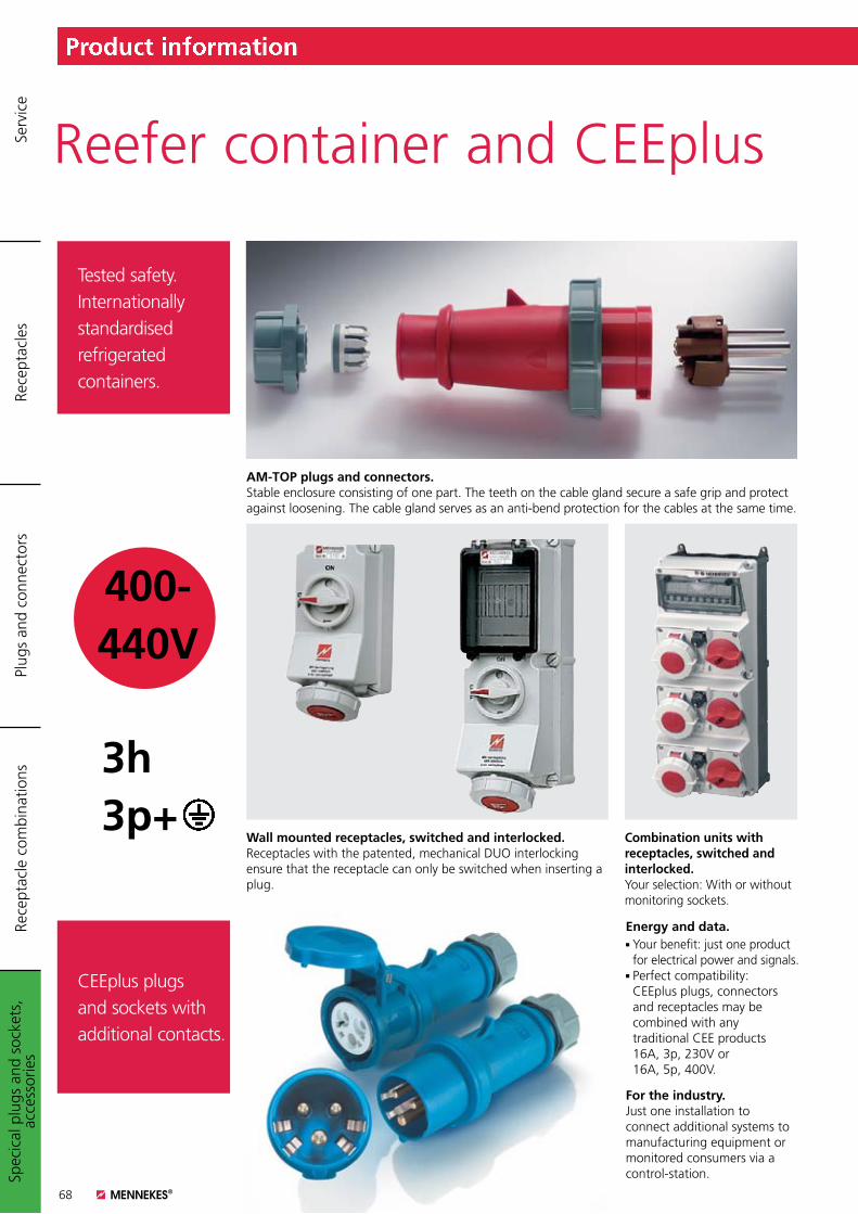
68
Product information
Tested safety. Internationally standardised refrigerated containers.
CEEplus plugs and sockets with additional contacts.
Spec
ical
plu
gs a
nd s
ocke
ts,
acce
ssor
ies
Plug
s an
d co
nnec
tors
Rece
ptac
les
Rece
ptac
le c
ombi
natio
nsSe
rvic
e
AM-TOP plugs and connectors.Stable enclosure consisting of one part. The teeth on the cable gland secure a safe grip and protect against loosening. The cable gland serves as an anti-bend protection for the cables at the same time.
400- 440V
3h 3p+
Energy and data.K Your benefit: just one product
for electrical power and signals.K Perfect compatibility: CEEplus plugs, connectors and receptacles may be combined with any traditional CEE products 16A, 3p, 230V or 16A, 5p, 400V.
For the industry.Just one installation toconnect additional systems tomanufacturing equipment ormonitored consumers via acontrol-station.
Reefer container and CEEplus
Wall mounted receptacles, switched and interlocked.Receptacles with the patented, mechanical DUO interlocking ensure that the receptacle can only be switched when inserting a plug.
Combination units with receptacles, switched and interlocked. Your selection: With or without monitoring sockets.
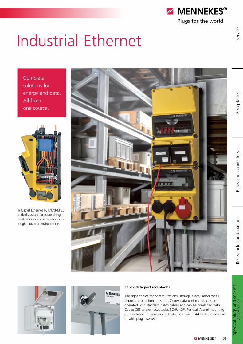
69
Product information
Complete solutions for energy and data. All from one source.
Industrial Ethernet
Industrial Ethernet by MENNEKES is ideally suited for establishing local networks or sub-networks in rough industrial environments.
Cepex data port receptacles The right choice for control stations, storage areas, laboratories, airports, production lines, etc. Cepex data port receptacles are operated with standard patch cables and can be combined with Cepex CEE and/or receptacles SCHUKO®. For wall-/panel mounting or installation in cable ducts. Protection type IP 44 with closed cover or with plug inserted.
Spec
ical
plu
gs a
nd s
ocke
ts,
acce
ssor
ies
Plug
s an
d co
nnec
tors
Rece
ptac
les
Rece
ptac
le c
ombi
natio
nsSe
rvic
e
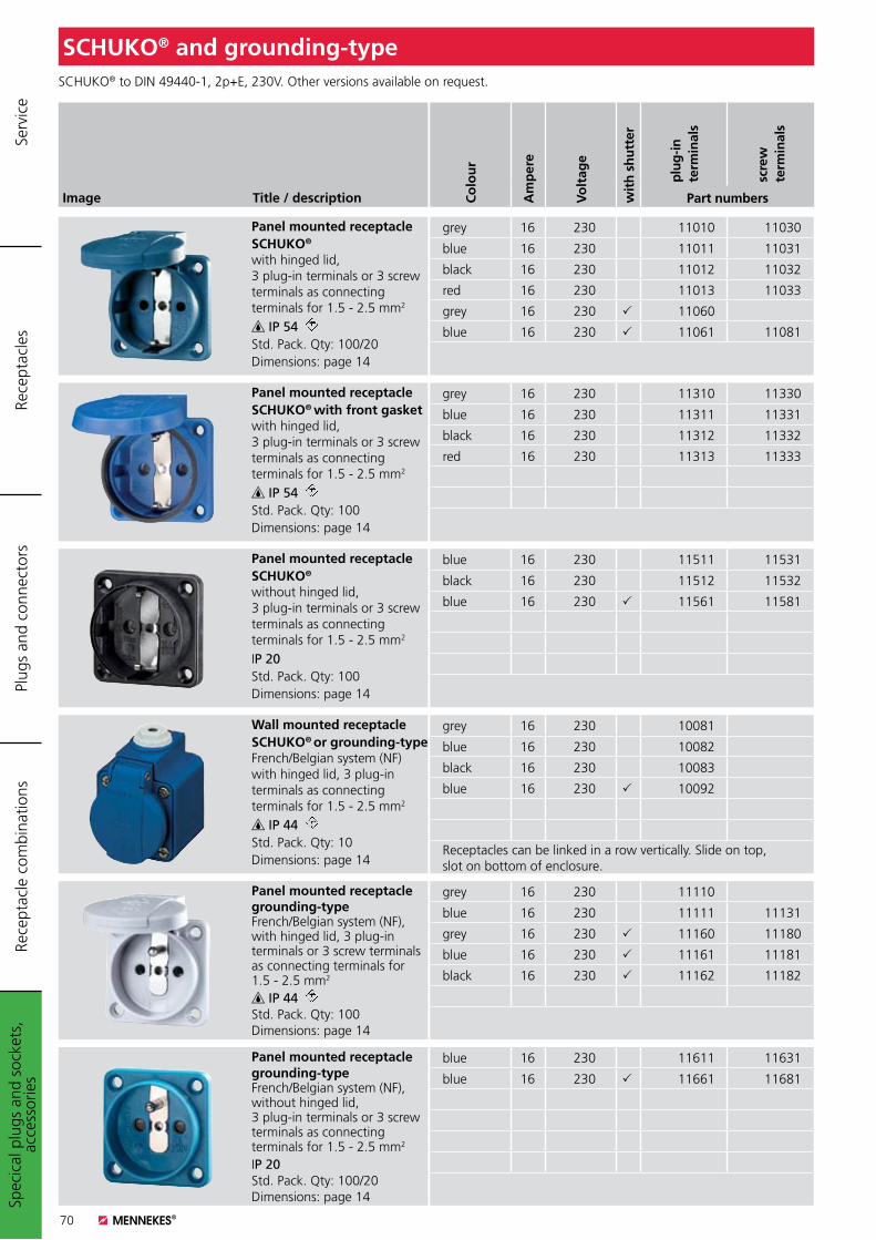
70
SCHUKO® and grounding-type
Image Title / description
Panel mounted receptacleSCHUKO®
with hinged lid, 3 plug-in terminals or 3 screw terminals as connecting terminals for 1.5 - 2.5 mm2
IP 54 Std. Pack. Qty: 100/20Dimensions: page 14
Panel mounted receptacleSCHUKO® with front gasketwith hinged lid, 3 plug-in terminals or 3 screw terminals as connecting terminals for 1.5 - 2.5 mm2
IP 54 Std. Pack. Qty: 100Dimensions: page 14
Panel mounted receptacleSCHUKO®
without hinged lid, 3 plug-in terminals or 3 screw terminals as connecting terminals for 1.5 - 2.5 mm2
IP 20Std. Pack. Qty: 100Dimensions: page 14
SCHUKO® to DIN 49440-1, 2p+E, 230V. Other versions available on request.
Co
lou
r
Am
per
e
Vo
ltag
e
wit
h s
hu
tter
plu
g-in
te
rmin
als
scre
wte
rmin
als
Part numbers
grey 16 230 11010 11030
blue 16 230 11011 11031
black 16 230 11012 11032
red 16 230 11013 11033
grey 16 230 11060
blue 16 230 11061 11081
grey 16 230 11310 11330
blue 16 230 11311 11331
black 16 230 11312 11332
red 16 230 11313 11333
blue 16 230 11511 11531
black 16 230 11512 11532
blue 16 230 11561 11581
Wall mounted receptacleSCHUKO® or grounding-typeFrench/Belgian system (NF) with hinged lid, 3 plug-in terminals as connecting terminals for 1.5 - 2.5 mm2
IP 44 Std. Pack. Qty: 10Dimensions: page 14
Panel mounted receptacle grounding-typeFrench/Belgian system (NF), with hinged lid, 3 plug-in terminals or 3 screw terminals as connecting terminals for 1.5 - 2.5 mm2
IP 44 Std. Pack. Qty: 100Dimensions: page 14
Panel mounted receptaclegrounding-type
French/Belgian system (NF), without hinged lid, 3 plug-in terminals or 3 screw terminals as connecting terminals for 1.5 - 2.5 mm2
IP 20Std. Pack. Qty: 100/20Dimensions: page 14
grey 16 230 10081
blue 16 230 10082
black 16 230 10083
blue 16 230 10092
Receptacles can be linked in a row vertically. Slide on top, slot on bottom of enclosure.
grey 16 230 11110
blue 16 230 11111 11131
grey 16 230 11160 11180
blue 16 230 11161 11181
black 16 230 11162 11182
blue 16 230 11611 11631
blue 16 230 11661 11681
Spec
ical
plu
gs a
nd s
ocke
ts,
acce
ssor
ies
Plug
s an
d co
nnec
tors
Rece
ptac
les
Rece
ptac
le c
ombi
natio
nsSe
rvic
e
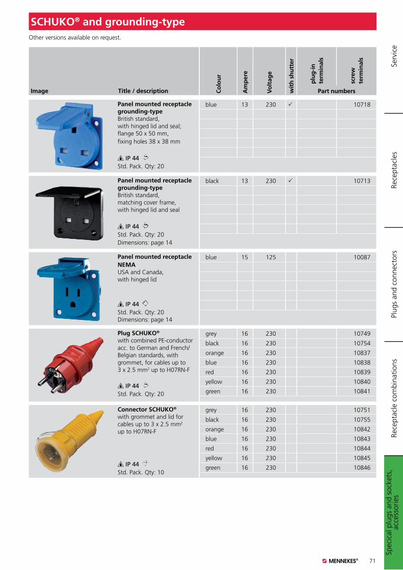
71
SCHUKO® and grounding-type
Image Title / description
Panel mounted receptacle grounding-typeBritish standard, with hinged lid and seal; flange 50 x 50 mm,fixing holes 38 x 38 mm
IP 44 Std. Pack. Qty: 20
Panel mounted receptacle grounding-typeBritish standard, matching cover frame, with hinged lid and seal
IP 44 Std. Pack. Qty: 20Dimensions: page 14
Panel mounted receptacleNEMAUSA and Canada, with hinged lid
IP 44 Std. Pack. Qty: 20 Dimensions: page 14
Other versions available on request.
Co
lou
r
Am
per
e
Vo
ltag
e
wit
h s
hu
tter
plu
g-in
te
rmin
als
scre
wte
rmin
als
Part numbers
blue 13 230 10718
black 13 230 10713
blue 15 125 10087
Plug SCHUKO®
with combined PE-conductor acc. to German and French/Belgian standards, with grommet, for cables up to 3 x 2.5 mm2 up to H07RN-F
IP 44 Std. Pack. Qty: 20
Connector SCHUKO®
with grommet and lid for cables up to 3 x 2.5 mm2 up to H07RN-F
IP 44 Std. Pack. Qty: 10
grey 16 230 10749
black 16 230 10754
orange 16 230 10837
blue 16 230 10838
red 16 230 10839
yellow 16 230 10840
green 16 230 10841
grey 16 230 10751
black 16 230 10755
orange 16 230 10842
blue 16 230 10843
red 16 230 10844
yellow 16 230 10845
green 16 230 10846
Spec
ical
plu
gs a
nd s
ocke
ts,
acce
ssor
ies
Plug
s an
d co
nnec
tors
Rece
ptac
les
Rece
ptac
le c
ombi
natio
nsSe
rvic
e
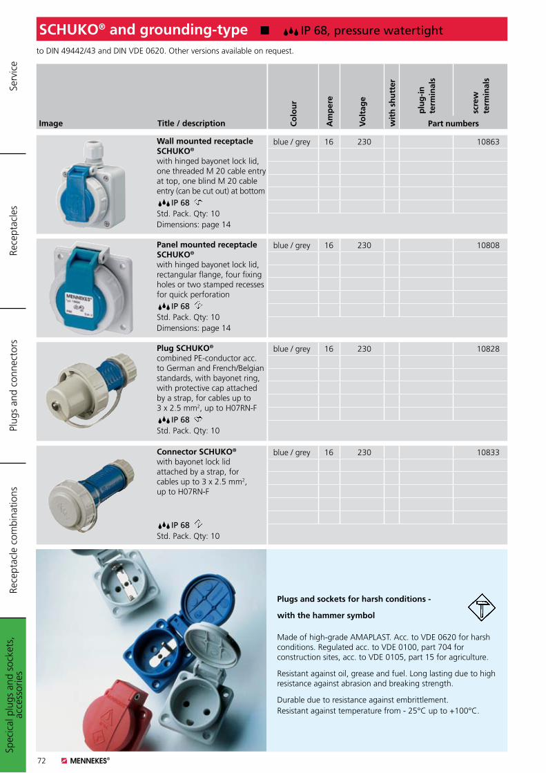
72
SCHUKO® and grounding-type K IP 68, pressure watertight
Image Title / description
Wall mounted receptacle SCHUKO®
with hinged bayonet lock lid, one threaded M 20 cable entry at top, one blind M 20 cable entry (can be cut out) at bottom IP 68 Std. Pack. Qty: 10Dimensions: page 14
Panel mounted receptacle SCHUKO®
with hinged bayonet lock lid, rectangular flange, four fixing holes or two stamped recesses for quick perforation IP 68 Std. Pack. Qty: 10Dimensions: page 14
Plug SCHUKO®
combined PE-conductor acc. to German and French/Belgian standards, with bayonet ring, with protective cap attached by a strap, for cables up to 3 x 2.5 mm2, up to H07RN-F IP 68 Std. Pack. Qty: 10
to DIN 49442/43 and DIN VDE 0620. Other versions available on request.
Co
lou
r
Am
per
e
Vo
ltag
e
wit
h s
hu
tter
plu
g-in
te
rmin
als
scre
wte
rmin
als
Part numbers
blue / grey 16 230 10863
blue / grey 16 230 10808
blue / grey 16 230 10828
Connector SCHUKO®
with bayonet lock lid attached by a strap, for cables up to 3 x 2.5 mm2, up to H07RN-F
IP 68 Std. Pack. Qty: 10
blue / grey 16 230 10833
Plugs and sockets for harsh conditions -
with the hammer symbol
Made of high-grade AMAPLAST. Acc. to VDE 0620 for harsh conditions. Regulated acc. to VDE 0100, part 704 for construction sites, acc. to VDE 0105, part 15 for agriculture.
Resistant against oil, grease and fuel. Long lasting due to high resistance against abrasion and breaking strength.
Durable due to resistance against embrittlement. Resistant against temperature from - 25°C up to +100°C.
Spec
ical
plu
gs a
nd s
ocke
ts,
acce
ssor
ies
Plug
s an
d co
nnec
tors
Rece
ptac
les
Rece
ptac
le c
ombi
natio
nsSe
rvic
e
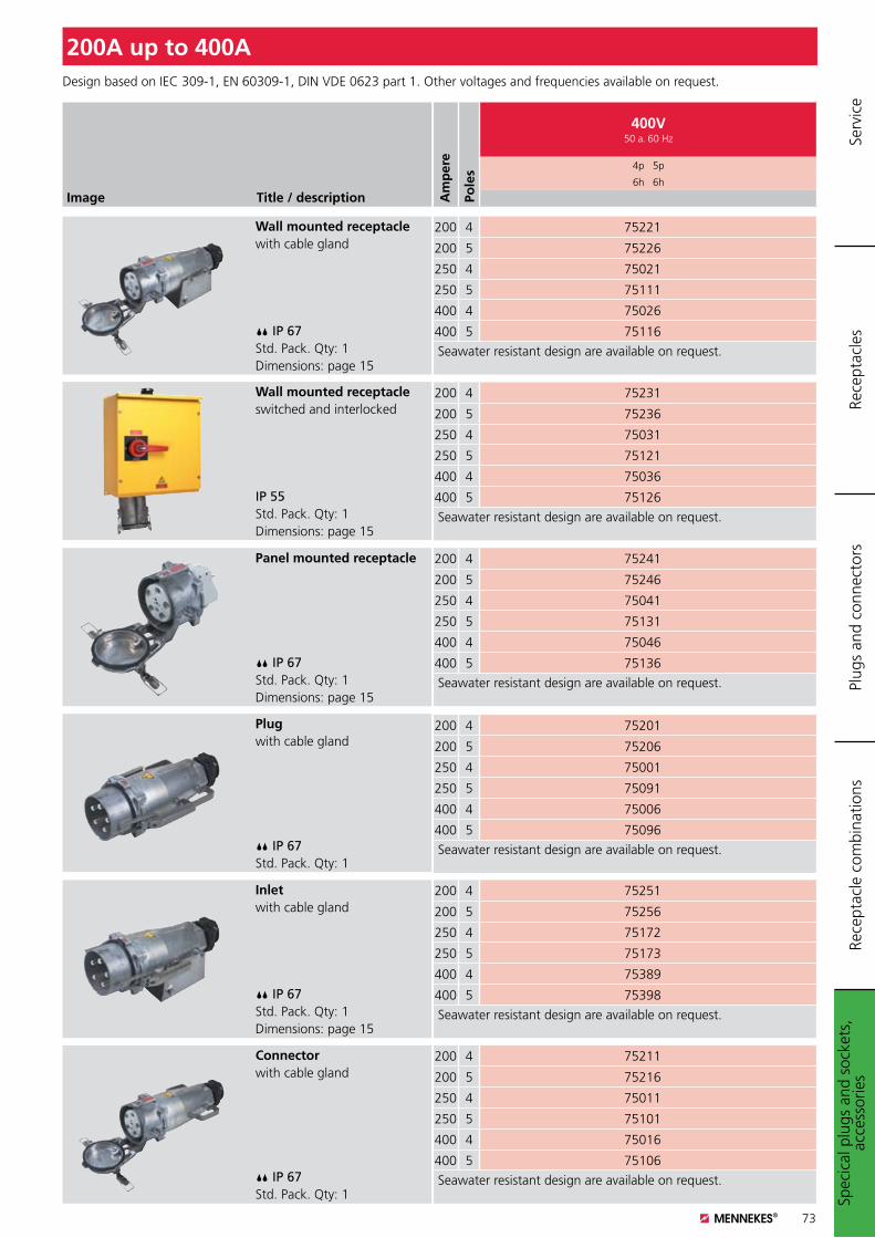
73
200 4 75221
200 5 75226
250 4 75021
250 5 75111
400 4 75026
400 5 75116
Seawater resistant design are available on request.
Image Title / description
Wall mounted receptaclewith cable gland
IP 67Std. Pack. Qty: 1Dimensions: page 15
Panel mounted receptacle
IP 67Std. Pack. Qty: 1Dimensions: page 15
Wall mounted receptacleswitched and interlocked
IP 55Std. Pack. Qty: 1Dimensions: page 15
Plugwith cable gland
IP 67Std. Pack. Qty: 1
Connectorwith cable gland
IP 67Std. Pack. Qty: 1
Inletwith cable gland
IP 67Std. Pack. Qty: 1Dimensions: page 15
Design based on IEC 309-1, EN 60309-1, DIN VDE 0623 part 1. Other voltages and frequencies available on request.
200A up to 400A
Am
per
e
Pole
s
400V50 a. 60 Hz
4p 5p
6h 6h
200 4 75251
200 5 75256
250 4 75172
250 5 75173
400 4 75389
400 5 75398
Seawater resistant design are available on request.
200 4 75211
200 5 75216
250 4 75011
250 5 75101
400 4 75016
400 5 75106
Seawater resistant design are available on request.
200 4 75201
200 5 75206
250 4 75001
250 5 75091
400 4 75006
400 5 75096
Seawater resistant design are available on request.
200 4 75241
200 5 75246
250 4 75041
250 5 75131
400 4 75046
400 5 75136
Seawater resistant design are available on request.
200 4 75231
200 5 75236
250 4 75031
250 5 75121
400 4 75036
400 5 75126
Seawater resistant design are available on request.
Spec
ical
plu
gs a
nd s
ocke
ts,
acce
ssor
ies
Plug
s an
d co
nnec
tors
Rece
ptac
les
Rece
ptac
le c
ombi
natio
nsSe
rvic
e
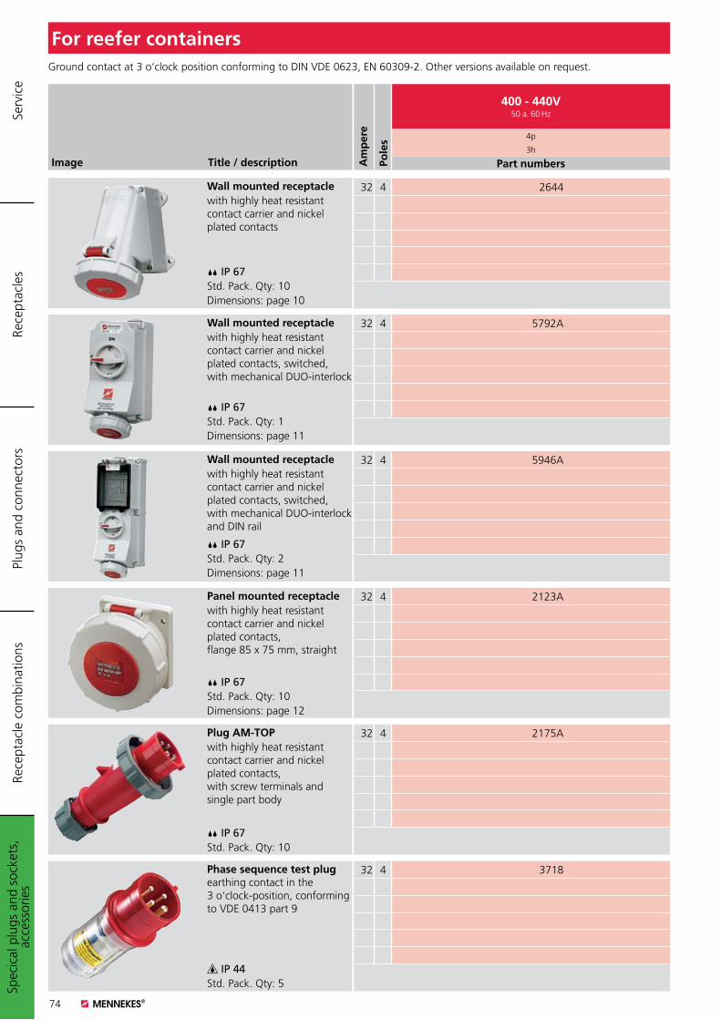
74
For reefer containers
Am
per
e
Pole
s
400 - 440V50 a. 60 Hz
4p
3h
Part numbersImage Title / description
Wall mounted receptaclewith highly heat resistant contact carrier and nickel plated contacts
IP 67Std. Pack. Qty: 10Dimensions: page 10
Wall mounted receptaclewith highly heat resistant contact carrier and nickel plated contacts, switched, with mechanical DUO-interlock
IP 67Std. Pack. Qty: 1Dimensions: page 11
Wall mounted receptaclewith highly heat resistant contact carrier and nickel plated contacts, switched, with mechanical DUO-interlock and DIN rail
IP 67Std. Pack. Qty: 2Dimensions: page 11
Panel mounted receptaclewith highly heat resistant contact carrier and nickel plated contacts, flange 85 x 75 mm, straight
IP 67Std. Pack. Qty: 10Dimensions: page 12
Plug AM-TOPwith highly heat resistant contact carrier and nickel plated contacts, with screw terminals and single part body
IP 67Std. Pack. Qty: 10
Phase sequence test plug earthing contact in the 3 o‘clock-position, conforming to VDE 0413 part 9
IP 44Std. Pack. Qty: 5
Ground contact at 3 o‘clock position conforming to DIN VDE 0623, EN 60309-2. Other versions available on request.
32 4 2644
32 4 5792A
32 4 5946A
32 4 2123A
32 4 2175A
32 4 3718
Spec
ical
plu
gs a
nd s
ocke
ts,
acce
ssor
ies
Plug
s an
d co
nnec
tors
Rece
ptac
les
Rece
ptac
le c
ombi
natio
nsSe
rvic
e
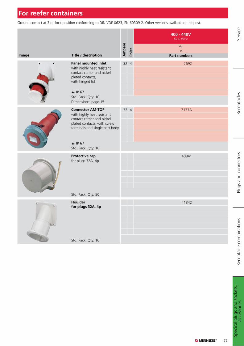
75
For reefer containers
Am
per
e
Pole
s
400 - 440V50 a. 60 Hz
4p
3h
Part numbersImage Title / description
Panel mounted inletwith highly heat resistant contact carrier and nickel plated contacts, with hinged lid
IP 67Std. Pack. Qty: 10Dimensions: page 15
Connector AM-TOPwith highly heat resistant contact carrier and nickel plated contacts, with screw terminals and single part body
IP 67Std. Pack. Qty: 10
Protective capfor plugs 32A, 4p
Std. Pack. Qty: 50
Houlder for plugs 32A, 4p
Std. Pack. Qty: 10
Ground contact at 3 o‘clock position conforming to DIN VDE 0623, EN 60309-2. Other versions available on request.
32 4 2692
32 4 2177A
40841
41342
Spec
ical
plu
gs a
nd s
ocke
ts,
acce
ssor
ies
Plug
s an
d co
nnec
tors
Rece
ptac
les
Rece
ptac
le c
ombi
natio
nsSe
rvic
e
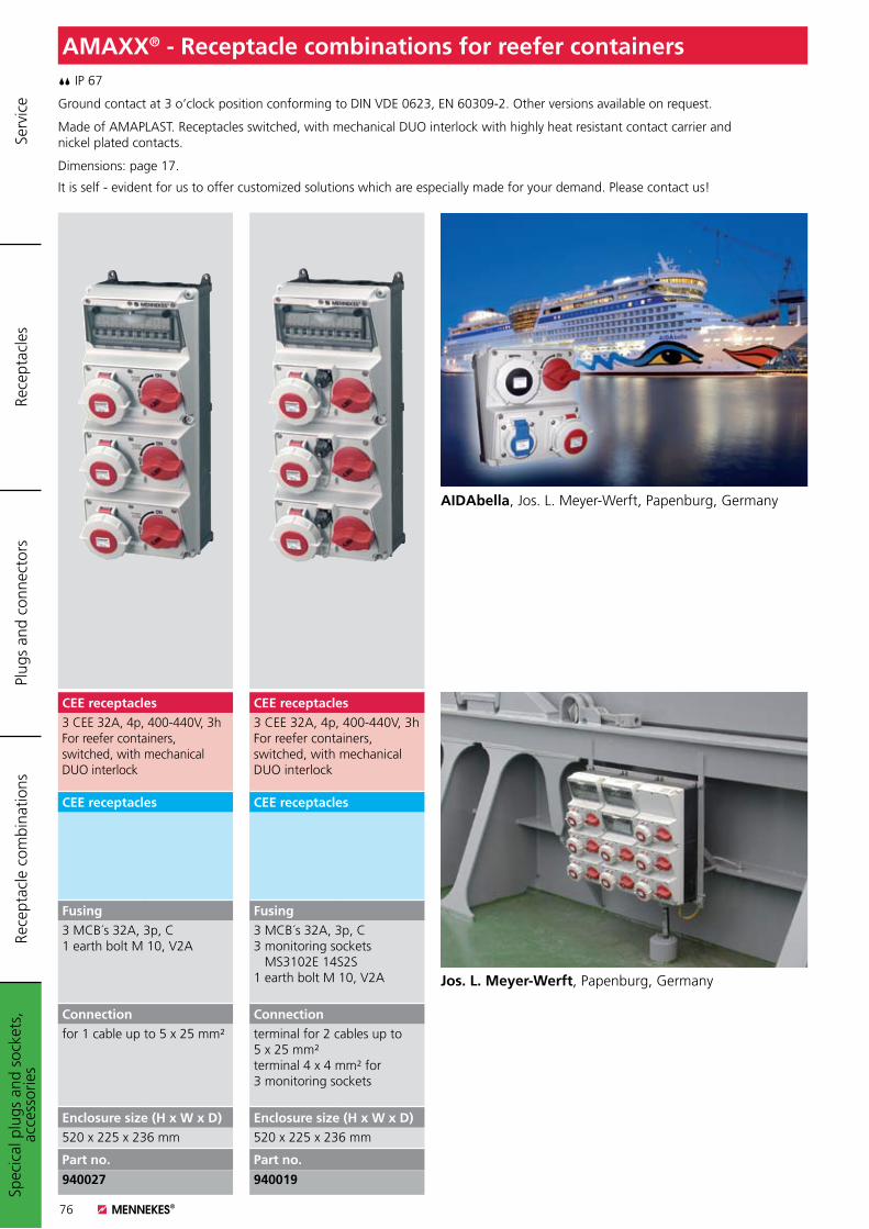
76
AMAXX® - Receptacle combinations for reefer containers IP 67
Ground contact at 3 o‘clock position conforming to DIN VDE 0623, EN 60309-2. Other versions available on request.
Made of AMAPLAST. Receptacles switched, with mechanical DUO interlock with highly heat resistant contact carrier and nickel plated contacts.
Dimensions: page 17.
It is self - evident for us to offer customized solutions which are especially made for your demand. Please contact us!
Spec
ical
plu
gs a
nd s
ocke
ts,
acce
ssor
ies
Plug
s an
d co
nnec
tors
Rece
ptac
les
Rece
ptac
le c
ombi
natio
nsSe
rvic
e
AIDAbella, Jos. L. Meyer-Werft, Papenburg, Germany
Jos. L. Meyer-Werft, Papenburg, Germany
CEE receptacles3 CEE 32A, 4p, 400-440V, 3hFor reefer containers,switched, with mechanicalDUO interlock
CEE receptacles
Fusing3 MCB´s 32A, 3p, C3 monitoring sockets MS3102E 14S2S1 earth bolt M 10, V2A
Connectionterminal for 2 cables up to 5 x 25 mm²terminal 4 x 4 mm² for 3 monitoring sockets
Enclosure size (H x W x D)520 x 225 x 236 mm
Part no.
940019
CEE receptacles3 CEE 32A, 4p, 400-440V, 3hFor reefer containers,switched, with mechanicalDUO interlock
CEE receptacles
Fusing3 MCB´s 32A, 3p, C1 earth bolt M 10, V2A
Connectionfor 1 cable up to 5 x 25 mm²
Enclosure size (H x W x D)520 x 225 x 236 mm
Part no.
940027
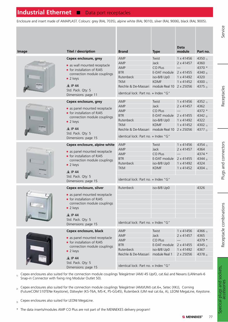
77
Spec
ical
plu
gs a
nd s
ocke
ts,
acce
ssor
ies
Plug
s an
d co
nnec
tors
Rece
ptac
les
Rece
ptac
le c
ombi
natio
nsSe
rvic
e
Industrial Ethernet K Data port receptacles
Brand TypeData module Part no.Titel / descriptionImage
Cepex enclosure, grey
K as wall mounted receptacleK for installation of RJ45 connection module couplingsK 2 keys
IP 44Std. Pack. Qty: 5Dimensions: page 11
Enclosure and insert made of AMAPLAST. Colours: grey (RAL 7035), alpine white (RAL 9010), silver (RAL 9006), black (RAL 9005).
Cepex enclosure, grey
K as panel mounted receptacleK for installation of RJ45 connection module couplingsK 2 keys
IP 44Std. Pack. Qty: 5Dimensions: page 15
Cepex enclosure, alpine white
K as panel mounted receptacleK for installation of RJ45 connection module couplingsK 2 keys
IP 44Std. Pack. Qty: 5Dimensions: page 15
Cepex enclosure, black
K as panel mounted receptacleK for installation of RJ45 connection module couplingsK 2 keys
IP 44Std. Pack. Qty: 5Dimensions: page 15
Cepex enclosure, silver
K as panel mounted receptacleK for installation of RJ45 connection module couplingsK 2 keys
IP 44Std. Pack. Qty: 5Dimensions: page 15
1) Cepex enclosures also suited for the connection module couplings Telegärtner (AMJ 45 Up/O, cat.6a) and Nexans (LANmark-6 Snap-in Connector with fixing ring Modular Outlet 50).
2) Cepex enclosures also suited for the connection module couplings Telegärtner (AMJ/UMJ cat.6+, Setec (XKJ), Corning (FutureCOM S10TENe Keystone), Dätwyler (KS-T6A, MS-K, PS-GG45), Rutenbeck (UM real cat.6a, A), LEONI MegaLine, Keystone.
3) Cepex enclosures also suited for LEONI MegaLine.
* The data inserts/modules AMP CO Plus are not part of the MENNEKES delivery program!
AMP Twist 1 x 41456 4350 1)
AMP Jack 2 x 41457 4360AMP CO Plus — 4370 *BTR E-DAT module 2 x 41455 4340 3)
Rutenbeck iso-8/8 Up0 1 x 41492 4320TKM KDMF 1 x 41452 4300 1)
Reichle & De-Massari module Real 10 2 x 25056 4375 2)
identical lock: Part no. + Index “G“
AMP Twist 1 x 41456 4352 1)
AMP Jack 2 x 41457 4362AMP CO Plus — 4372 *BTR E-DAT module 2 x 41455 4342 3)
Rutenbeck iso-8/8 Up0 1 x 41492 4322TKM KDMF 1 x 41452 4302 1)
Reichle & De-Massari module Real 10 2 x 25056 4377 2)
identical lock: Part no. + Index “G“
AMP Twist 1 x 41456 4354 1)
AMP Jack 2 x 41457 4364AMP CO Plus — 4374 *BTR E-DAT module 2 x 41455 4344 3)
Rutenbeck iso-8/8 Up0 1 x 41492 4324TKM KDMF 1 x 41452 4304 1)
identical lock: Part no. + Index “G“
AMP Twist 1 x 41456 4366 1)
AMP Jack 2 x 41457 4365AMP CO Plus — 4379 *BTR E-DAT module 2 x 41455 4345 3)
Rutenbeck iso-8/8 Up0 1 x 41492 4367Reichle & De-Massari module Real 1 2 x 25056 4378 2)
identical lock: Part no. + Index “G“
Rutenbeck iso-8/8 Up0 4326
identical lock: Part no. + Index “G“
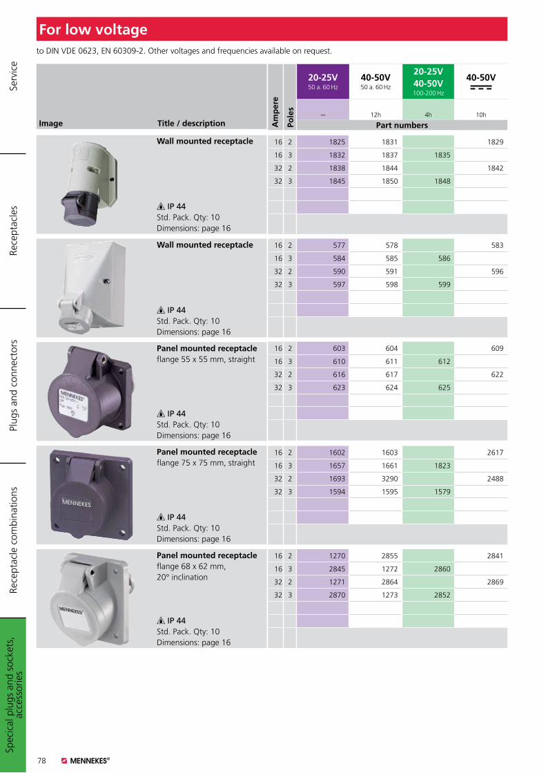
78
Am
per
e
Pole
s
20-25V50 a. 60 Hz
40-50V50 a. 60 Hz
20-25V40-50V100-200 Hz
40-50V
--- 12h 4h 10h
Part numbersImage Title / description
Wall mounted receptacle
IP 44Std. Pack. Qty: 10Dimensions: page 16
Wall mounted receptacle
IP 44Std. Pack. Qty: 10Dimensions: page 16
Panel mounted receptacleflange 55 x 55 mm, straight
IP 44Std. Pack. Qty: 10Dimensions: page 16
Panel mounted receptacleflange 75 x 75 mm, straight
IP 44Std. Pack. Qty: 10Dimensions: page 16
Panel mounted receptacleflange 68 x 62 mm, 20° inclination
IP 44Std. Pack. Qty: 10Dimensions: page 16
to DIN VDE 0623, EN 60309-2. Other voltages and frequencies available on request.
For low voltage
16 2 1825 1831 1829
16 3 1832 1837 1835
32 2 1838 1844 1842
32 3 1845 1850 1848
16 2 577 578 583
16 3 584 585 586
32 2 590 591 596
32 3 597 598 599
16 2 603 604 609
16 3 610 611 612
32 2 616 617 622
32 3 623 624 625
16 2 1602 1603 2617
16 3 1657 1661 1823
32 2 1693 3290 2488
32 3 1594 1595 1579
16 2 1270 2855 2841
16 3 2845 1272 2860
32 2 1271 2864 2869
32 3 2870 1273 2852
Spec
ical
plu
gs a
nd s
ocke
ts,
acce
ssor
ies
Plug
s an
d co
nnec
tors
Rece
ptac
les
Rece
ptac
le c
ombi
natio
nsSe
rvic
e
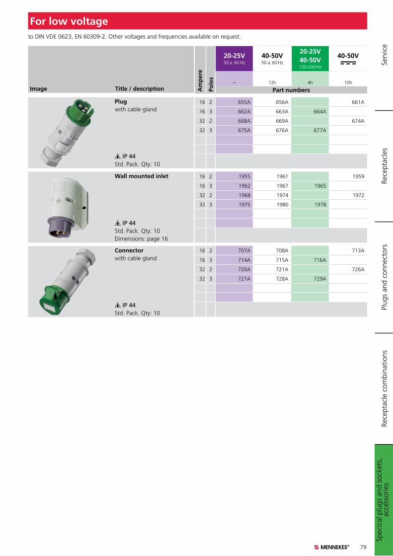
79
Am
per
e
Pole
s
20-25V50 a. 60 Hz
40-50V50 a. 60 Hz
20-25V40-50V100-200 Hz
40-50V
--- 12h 4h 10h
Part numbersImage Title / description
Plugwith cable gland
IP 44Std. Pack. Qty: 10
Wall mounted inlet
IP 44Std. Pack. Qty: 10Dimensions: page 16
Connectorwith cable gland
IP 44Std. Pack. Qty: 10
to DIN VDE 0623, EN 60309-2. Other voltages and frequencies available on request.
For low voltage
16 2 655A 656A 661A
16 3 662A 663A 664A
32 2 668A 669A 674A
32 3 675A 676A 677A
16 2 1955 1961 1959
16 3 1962 1967 1965
32 2 1968 1974 1972
32 3 1975 1980 1978
16 2 707A 708A 713A
16 3 714A 715A 716A
32 2 720A 721A 726A
32 3 727A 728A 729A
Spec
ical
plu
gs a
nd s
ocke
ts,
acce
ssor
ies
Plug
s an
d co
nnec
tors
Rece
ptac
les
Rece
ptac
le c
ombi
natio
nsSe
rvic
e
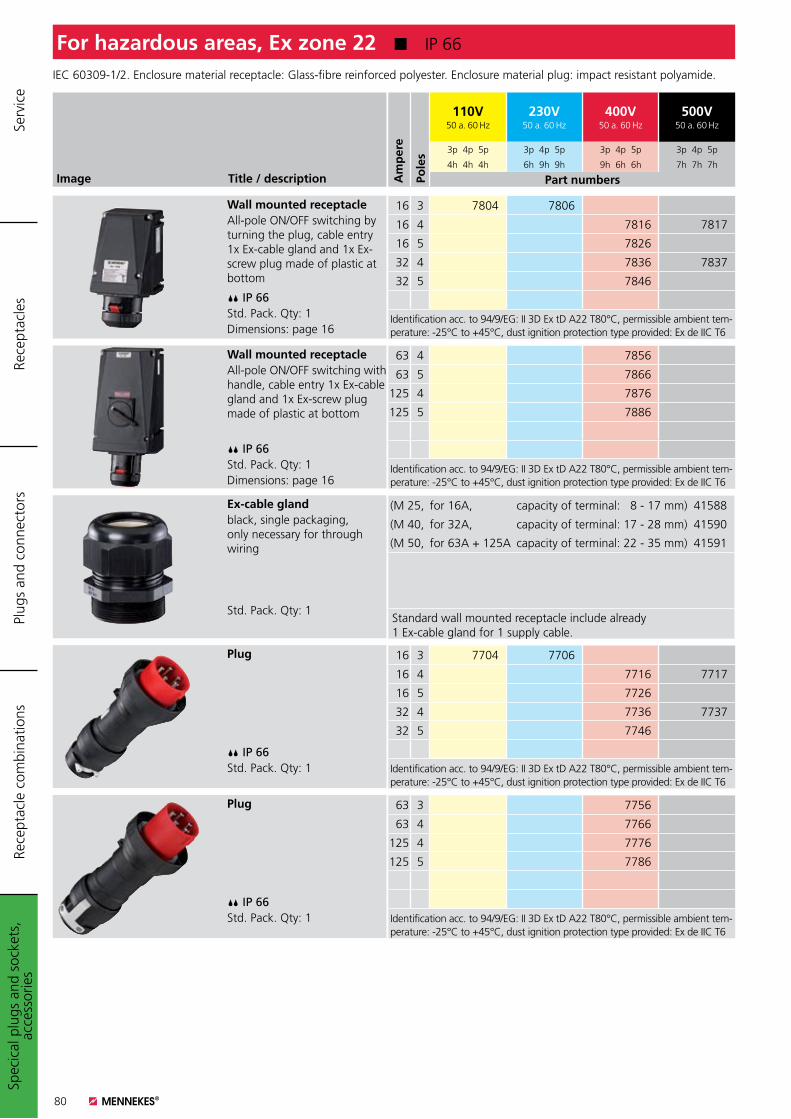
80
Spec
ical
plu
gs a
nd s
ocke
ts,
acce
ssor
ies
Plug
s an
d co
nnec
tors
Rece
ptac
les
Rece
ptac
le c
ombi
natio
nsSe
rvic
e
Am
per
e
Pole
s
110V50 a. 60 Hz
230V50 a. 60 Hz
400V50 a. 60 Hz
500V50 a. 60 Hz
3p 4p 5p 3p 4p 5p 3p 4p 5p 3p 4p 5p
4h 4h 4h 6h 9h 9h 9h 6h 6h 7h 7h 7h
Part numbersImage Title / description
IEC 60309-1/2. Enclosure material receptacle: Glass-fibre reinforced polyester. Enclosure material plug: impact resistant polyamide.
For hazardous areas, Ex zone 22 K IP 66
Wall mounted receptacleAll-pole ON/OFF switching by turning the plug, cable entry 1x Ex-cable gland and 1x Ex-screw plug made of plastic at bottom
IP 66Std. Pack. Qty: 1Dimensions: page 16
Wall mounted receptacleAll-pole ON/OFF switching with handle, cable entry 1x Ex-cable gland and 1x Ex-screw plug made of plastic at bottom
IP 66Std. Pack. Qty: 1Dimensions: page 16
Ex-cable glandblack, single packaging, only necessary for through wiring
Std. Pack. Qty: 1
Plug
IP 66Std. Pack. Qty: 1
Plug
IP 66Std. Pack. Qty: 1
16 3 7804 7806
16 4 7816 7817
16 5 7826
32 4 7836 7837
32 5 7846
Identification acc. to 94/9/EG: II 3D Ex tD A22 T80°C, permissible ambient tem-perature: -25°C to +45°C, dust ignition protection type provided: Ex de IIC T6
63 4 7856
63 5 7866
125 4 7876
125 5 7886
Identification acc. to 94/9/EG: II 3D Ex tD A22 T80°C, permissible ambient tem-perature: -25°C to +45°C, dust ignition protection type provided: Ex de IIC T6
(M 25, for 16A, capacity of terminal: 8 - 17 mm) 41588
(M 40, for 32A, capacity of terminal: 17 - 28 mm) 41590
(M 50, for 63A + 125A capacity of terminal: 22 - 35 mm) 41591
Standard wall mounted receptacle include already 1 Ex-cable gland for 1 supply cable.
16 3 7704 7706
16 4 7716 7717
16 5 7726
32 4 7736 7737
32 5 7746
Identification acc. to 94/9/EG: II 3D Ex tD A22 T80°C, permissible ambient tem-perature: -25°C to +45°C, dust ignition protection type provided: Ex de IIC T6
63 3 7756
63 4 7766
125 4 7776
125 5 7786
Identification acc. to 94/9/EG: II 3D Ex tD A22 T80°C, permissible ambient tem-perature: -25°C to +45°C, dust ignition protection type provided: Ex de IIC T6
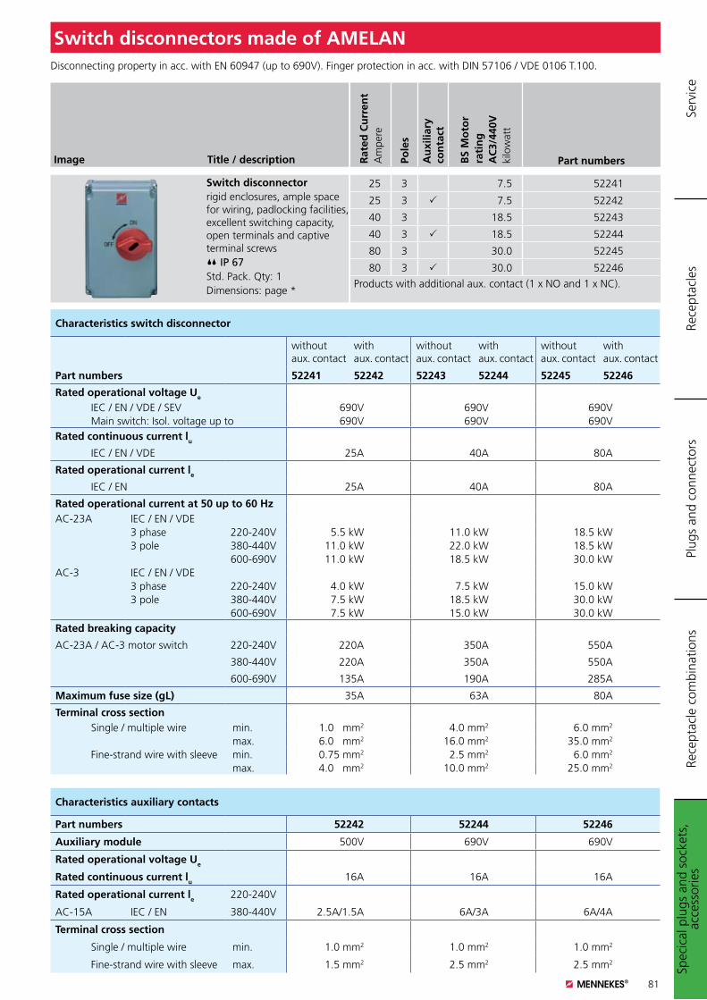
81
Image Title / description
Switch disconnectorrigid enclosures, ample space for wiring, padlocking facilities, excellent switching capacity, open terminals and captive terminal screws IP 67 Std. Pack. Qty: 1Dimensions: page *
Switch disconnectors made of AMELAN
Rat
ed C
urr
ent
Am
pere
Pole
s
Au
xilia
ry
con
tact
BS
Mo
tor
rati
ng
AC
3/44
0Vki
low
att
Part numbers
25 3 7.5 52241
25 3 7.5 52242
40 3 18.5 52243
40 3 18.5 52244
80 3 30.0 52245
80 3 30.0 52246
Products with additional aux. contact (1 x NO and 1 x NC).
Disconnecting property in acc. with EN 60947 (up to 690V). Finger protection in acc. with DIN 57106 / VDE 0106 T.100.
Characteristics switch disconnector
without aux. contact
with aux. contact
without aux. contact
with aux. contact
without aux. contact
with aux. contact
Part numbers 52241 52242 52243 52244 52245 52246
Rated operational voltage Ue
IEC / EN / VDE / SEV 690V 690V 690VMain switch: Isol. voltage up to 690V 690V 690V
Rated continuous current lu
IEC / EN / VDE 25A 40A 80A
Rated operational current le
IEC / EN 25A 40A 80A
Rated operational current at 50 up to 60 HzAC-23A IEC / EN / VDE
3 phase 220-240V 5.5 kW 11.0 kW 18.5 kW3 pole 380-440V 11.0 kW 22.0 kW 18.5 kW
600-690V 11.0 kW 18.5 kW 30.0 kWAC-3 IEC / EN / VDE
3 phase 220-240V 4.0 kW 7.5 kW 15.0 kW3 pole 380-440V 7.5 kW 18.5 kW 30.0 kW
600-690V 7.5 kW 15.0 kW 30.0 kWRated breaking capacity
AC-23A / AC-3 motor switch 220-240V 220A 350A 550A
380-440V 220A 350A 550A
600-690V 135A 190A 285A
Maximum fuse size (gL) 35A 63A 80A
Terminal cross sectionSingle / multiple wire min. 1.0 mm2 4.0 mm2 6.0 mm2
max. 6.0 mm2 16.0 mm2 35.0 mm2
Fine-strand wire with sleeve min. 0.75 mm2 2.5 mm2 6.0 mm2
max. 4.0 mm2 10.0 mm2 25.0 mm2
Characteristics auxiliary contacts
Part numbers 52242 52244 52246
Auxiliary module 500V 690V 690V
Rated operational voltage Ue
Rated continuous current lu 16A 16A 16A
Rated operational current le 220-240V
AC-15A IEC / EN 380-440V 2.5A/1.5A 6A/3A 6A/4A
Terminal cross section
Single / multiple wire min. 1.0 mm2 1.0 mm2 1.0 mm2
Fine-strand wire with sleeve max. 1.5 mm2 2.5 mm2 2.5 mm2
Spec
ical
plu
gs a
nd s
ocke
ts,
acce
ssor
ies
Plug
s an
d co
nnec
tors
Rece
ptac
les
Rece
ptac
le c
ombi
natio
nsSe
rvic
e
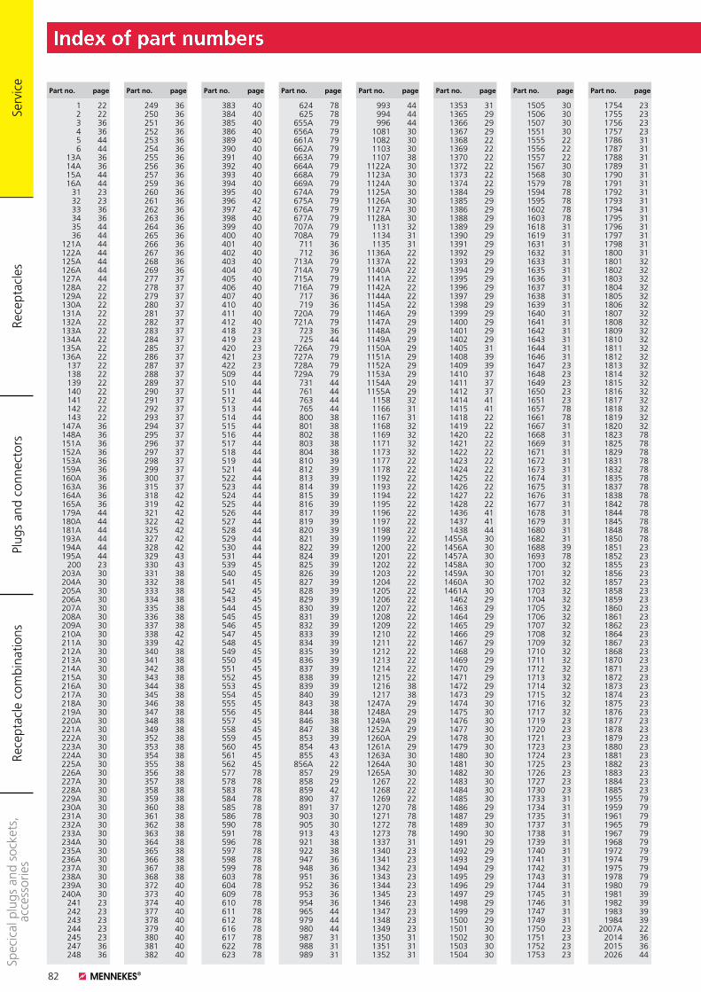
82
Plug
s an
d co
nnec
tors
Rece
ptac
les
Rece
ptac
le c
ombi
natio
nsSp
ecic
al p
lugs
and
soc
kets
, ac
cess
orie
s Se
rvic
e
Part no. page Part no. page Part no. page Part no. page Part no. page Part no. page Part no. page Part no. page
1 22 2 22 3 36 4 36 5 44 6 44 13A 36 14A 36 15A 44 16A 44 31 23 32 23 33 36 34 36 35 44 36 44 121A 44 122A 44 125A 44 126A 44 127A 44 128A 22 129A 22 130A 22 131A 22 132A 22 133A 22 134A 22 135A 22 136A 22 137 22 138 22 139 22 140 22 141 22 142 22 143 22 147A 36 148A 36 151A 36 152A 36 153A 36 159A 36 160A 36 163A 36 164A 36 165A 36 179A 44 180A 44 181A 44 193A 44 194A 44 195A 44 200 23 203A 30 204A 30 205A 30 206A 30 207A 30 208A 30 209A 30 210A 30 211A 30 212A 30 213A 30 214A 30 215A 30 216A 30 217A 30 218A 30 219A 30 220A 30 221A 30 222A 30 223A 30 224A 30 225A 30 226A 30 227A 30 228A 30 229A 30 230A 30 231A 30 232A 30 233A 30 234A 30 235A 30 236A 30 237A 30 238A 30 239A 30 240A 30 241 23 242 23 243 23 244 23 245 23 247 36 248 36
249 36 250 36 251 36 252 36 253 36 254 36 255 36 256 36 257 36 259 36 260 36 261 36 262 36 263 36 264 36 265 36 266 36 267 36 268 36 269 36 277 37 278 37 279 37 280 37 281 37 282 37 283 37 284 37 285 37 286 37 287 37 288 37 289 37 290 37 291 37 292 37 293 37 294 37 295 37 296 37 297 37 298 37 299 37 300 37 315 37 318 42 319 42 321 42 322 42 325 42 327 42 328 42 329 43 330 43 331 38 332 38 333 38 334 38 335 38 336 38 337 38 338 42 339 42 340 38 341 38 342 38 343 38 344 38 345 38 346 38 347 38 348 38 349 38 352 38 353 38 354 38 355 38 356 38 357 38 358 38 359 38 360 38 361 38 362 38 363 38 364 38 365 38 366 38 367 38 368 38 372 40 373 40 374 40 377 40 378 40 379 40 380 40 381 40 382 40
383 40 384 40 385 40 386 40 389 40 390 40 391 40 392 40 393 40 394 40 395 40 396 42 397 42 398 40 399 40 400 40 401 40 402 40 403 40 404 40 405 40 406 40 407 40 410 40 411 40 412 40 418 23 419 23 420 23 421 23 422 23 509 44 510 44 511 44 512 44 513 44 514 44 515 44 516 44 517 44 518 44 519 44 521 44 522 44 523 44 524 44 525 44 526 44 527 44 528 44 529 44 530 44 531 44 539 45 540 45 541 45 542 45 543 45 544 45 545 45 546 45 547 45 548 45 549 45 550 45 551 45 552 45 553 45 554 45 555 45 556 45 557 45 558 45 559 45 560 45 561 45 562 45 577 78 578 78 583 78 584 78 585 78 586 78 590 78 591 78 596 78 597 78 598 78 599 78 603 78 604 78 609 78 610 78 611 78 612 78 616 78 617 78 622 78 623 78
624 78 625 78 655A 79 656A 79 661A 79 662A 79 663A 79 664A 79 668A 79 669A 79 674A 79 675A 79 676A 79 677A 79 707A 79 708A 79 711 36 712 36 713A 79 714A 79 715A 79 716A 79 717 36 719 36 720A 79 721A 79 723 36 725 44 726A 79 727A 79 728A 79 729A 79 731 44 761 44 763 44 765 44 800 38 801 38 802 38 803 38 804 38 810 39 812 39 813 39 814 39 815 39 816 39 817 39 819 39 820 39 821 39 822 39 824 39 825 39 826 39 827 39 828 39 829 39 830 39 831 39 832 39 833 39 834 39 835 39 836 39 837 39 838 39 839 39 840 39 843 38 844 38 846 38 847 38 853 39 854 43 855 43 856A 22 857 29 858 29 859 42 890 37 891 37 903 30 905 30 913 43 921 38 922 38 947 36 948 36 951 36 952 36 953 36 954 36 965 44 979 44 980 44 987 31 988 31 989 31
993 44 994 44 996 44 1081 30 1082 30 1103 30 1107 38 1122A 30 1123A 30 1124A 30 1125A 30 1126A 30 1127A 30 1128A 30 1131 32 1134 31 1135 31 1136A 22 1137A 22 1140A 22 1141A 22 1142A 22 1144A 22 1145A 22 1146A 29 1147A 29 1148A 29 1149A 29 1150A 29 1151A 29 1152A 29 1153A 29 1154A 29 1155A 29 1158 32 1166 31 1167 31 1168 32 1169 32 1171 32 1173 32 1177 22 1178 22 1192 22 1193 22 1194 22 1195 22 1196 22 1197 22 1198 22 1199 22 1200 22 1201 22 1202 22 1203 22 1204 22 1205 22 1206 22 1207 22 1208 22 1209 22 1210 22 1211 22 1212 22 1213 22 1214 22 1215 22 1216 38 1217 38 1247A 29 1248A 29 1249A 29 1252A 29 1260A 29 1261A 29 1263A 30 1264A 30 1265A 30 1267 22 1268 22 1269 22 1270 78 1271 78 1272 78 1273 78 1337 31 1340 23 1341 23 1342 23 1343 23 1344 23 1345 23 1346 23 1347 23 1348 23 1349 23 1350 31 1351 31 1352 31
1353 31 1365 29 1366 29 1367 29 1368 22 1369 22 1370 22 1372 22 1373 22 1374 22 1384 29 1385 29 1386 29 1388 29 1389 29 1390 29 1391 29 1392 29 1393 29 1394 29 1395 29 1396 29 1397 29 1398 29 1399 29 1400 29 1401 29 1402 29 1405 31 1408 39 1409 39 1410 37 1411 37 1412 37 1414 41 1415 41 1418 22 1419 22 1420 22 1421 22 1422 22 1423 22 1424 22 1425 22 1426 22 1427 22 1428 22 1436 41 1437 41 1438 44 1455A 30 1456A 30 1457A 30 1458A 30 1459A 30 1460A 30 1461A 30 1462 29 1463 29 1464 29 1465 29 1466 29 1467 29 1468 29 1469 29 1470 29 1471 29 1472 29 1473 29 1474 30 1475 30 1476 30 1477 30 1478 30 1479 30 1480 30 1481 30 1482 30 1483 30 1484 30 1485 30 1486 29 1487 29 1489 30 1490 30 1491 29 1492 29 1493 29 1494 29 1495 29 1496 29 1497 29 1498 29 1499 29 1500 29 1501 30 1502 30 1503 30 1504 30
1505 30 1506 30 1507 30 1551 30 1555 22 1556 22 1557 22 1567 30 1568 30 1579 78 1594 78 1595 78 1602 78 1603 78 1618 31 1619 31 1631 31 1632 31 1633 31 1635 31 1636 31 1637 31 1638 31 1639 31 1640 31 1641 31 1642 31 1643 31 1644 31 1646 31 1647 23 1648 23 1649 23 1650 23 1651 23 1657 78 1661 78 1667 31 1668 31 1669 31 1671 31 1672 31 1673 31 1674 31 1675 31 1676 31 1677 31 1678 31 1679 31 1680 31 1682 31 1688 39 1693 78 1700 32 1701 32 1702 32 1703 32 1704 32 1705 32 1706 32 1707 32 1708 32 1709 32 1710 32 1711 32 1712 32 1713 32 1714 32 1715 32 1716 32 1717 32 1719 23 1720 23 1721 23 1723 23 1724 23 1725 23 1726 23 1727 23 1730 23 1733 31 1734 31 1735 31 1737 31 1738 31 1739 31 1740 31 1741 31 1742 31 1743 31 1744 31 1745 31 1746 31 1747 31 1749 31 1750 23 1751 23 1752 23 1753 23
1754 23 1755 23 1756 23 1757 23 1786 31 1787 31 1788 31 1789 31 1790 31 1791 31 1792 31 1793 31 1794 31 1795 31 1796 31 1797 31 1798 31 1800 31 1801 32 1802 32 1803 32 1804 32 1805 32 1806 32 1807 32 1808 32 1809 32 1810 32 1811 32 1812 32 1813 32 1814 32 1815 32 1816 32 1817 32 1818 32 1819 32 1820 32 1823 78 1825 78 1829 78 1831 78 1832 78 1835 78 1837 78 1838 78 1842 78 1844 78 1845 78 1848 78 1850 78 1851 23 1852 23 1855 23 1856 23 1857 23 1858 23 1859 23 1860 23 1861 23 1862 23 1864 23 1867 23 1868 23 1870 23 1871 23 1872 23 1873 23 1874 23 1875 23 1876 23 1877 23 1878 23 1879 23 1880 23 1881 23 1882 23 1883 23 1884 23 1885 23 1955 79 1959 79 1961 79 1965 79 1967 79 1968 79 1972 79 1974 79 1975 79 1978 79 1980 79 1981 39 1982 39 1983 39 1984 39 2007A 22 2014 36 2015 36 2026 44
Index of part numbers
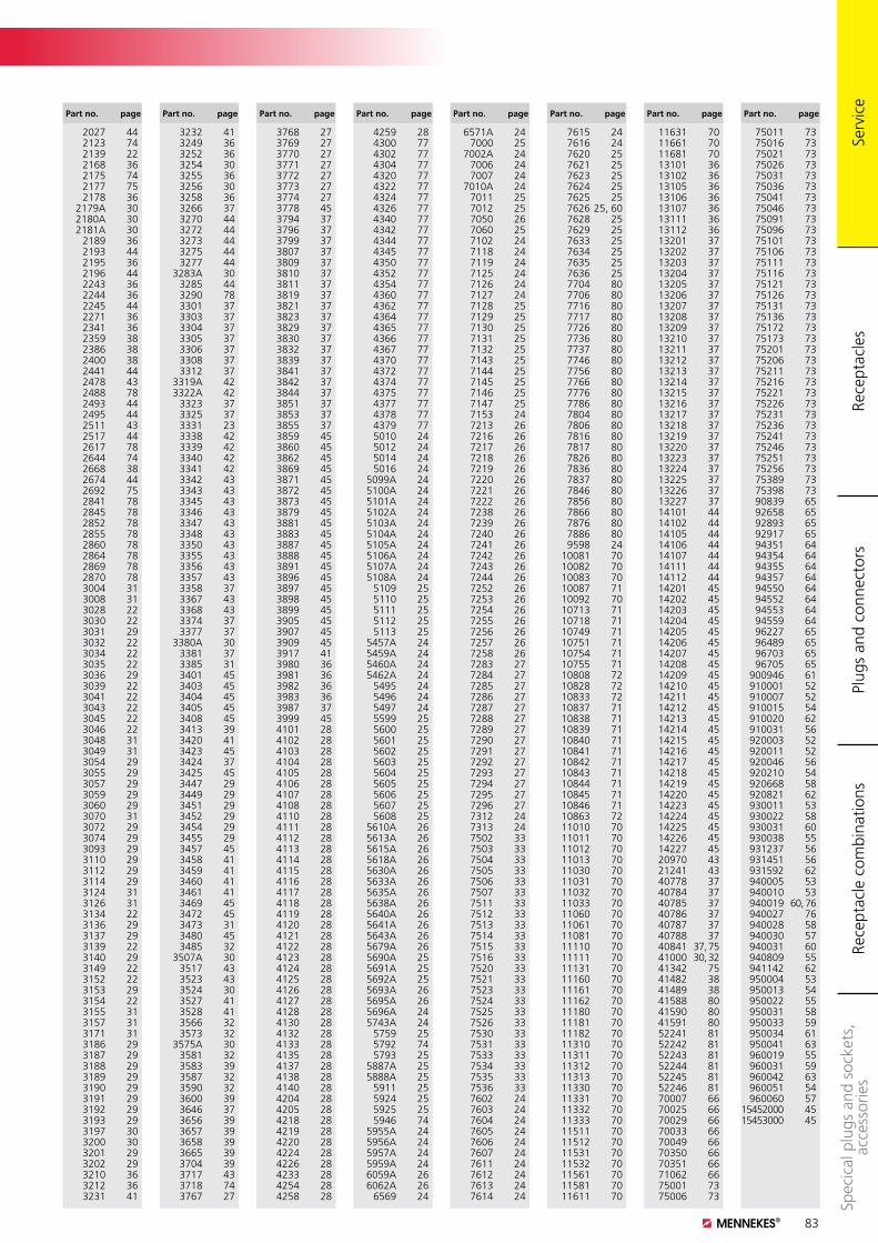
83
Part no. page Part no. page Part no. page Part no. page Part no. page Part no. page Part no. page Part no. page
Plug
s an
d co
nnec
tors
Rece
ptac
les
Rece
ptac
le c
ombi
natio
nsSp
ecic
al p
lugs
and
soc
kets
, ac
cess
orie
s Se
rvic
e
2027 44 2123 74 2139 22 2168 36 2175 74 2177 75 2178 36 2179A 30 2180A 30 2181A 30 2189 36 2193 44 2195 36 2196 44 2243 36 2244 36 2245 44 2271 36 2341 36 2359 38 2386 38 2400 38 2441 44 2478 43 2488 78 2493 44 2495 44 2511 43 2517 44 2617 78 2644 74 2668 38 2674 44 2692 75 2841 78 2845 78 2852 78 2855 78 2860 78 2864 78 2869 78 2870 78 3004 31 3008 31 3028 22 3030 22 3031 29 3032 22 3034 22 3035 22 3036 29 3039 22 3041 22 3043 22 3045 22 3046 22 3048 31 3049 31 3054 29 3055 29 3057 29 3059 29 3060 29 3070 31 3072 29 3074 29 3093 29 3110 29 3112 29 3114 29 3124 31 3126 31 3134 22 3136 29 3137 29 3139 22 3140 29 3149 22 3152 22 3153 29 3154 22 3155 31 3157 31 3171 31 3186 29 3187 29 3188 29 3189 29 3190 29 3191 29 3192 29 3193 29 3197 30 3200 30 3201 29 3202 29 3210 36 3212 36 3231 41
3232 41 3249 36 3252 36 3254 30 3255 36 3256 30 3258 36 3266 37 3270 44 3272 44 3273 44 3275 44 3277 44 3283A 30 3285 44 3290 78 3301 37 3303 37 3304 37 3305 37 3306 37 3308 37 3312 37 3319A 42 3322A 42 3323 37 3325 37 3331 23 3338 42 3339 42 3340 42 3341 42 3342 43 3343 43 3345 43 3346 43 3347 43 3348 43 3350 43 3355 43 3356 43 3357 43 3358 37 3367 43 3368 43 3374 37 3377 37 3380A 30 3381 37 3385 31 3401 45 3403 45 3404 45 3405 45 3408 45 3413 39 3420 41 3423 45 3424 37 3425 45 3447 29 3449 29 3451 29 3452 29 3454 29 3455 29 3457 45 3458 41 3459 41 3460 41 3461 41 3469 45 3472 45 3473 31 3480 45 3485 32 3507A 30 3517 43 3523 43 3524 30 3527 41 3528 41 3566 32 3573 32 3575A 30 3581 32 3583 39 3587 32 3590 32 3600 39 3646 37 3656 39 3657 39 3658 39 3665 39 3704 39 3717 43 3718 74 3767 27
3768 27 3769 27 3770 27 3771 27 3772 27 3773 27 3774 27 3778 45 3794 37 3796 37 3799 37 3807 37 3809 37 3810 37 3811 37 3819 37 3821 37 3823 37 3829 37 3830 37 3832 37 3839 37 3841 37 3842 37 3844 37 3851 37 3853 37 3855 37 3859 45 3860 45 3862 45 3869 45 3871 45 3872 45 3873 45 3879 45 3881 45 3883 45 3887 45 3888 45 3891 45 3896 45 3897 45 3898 45 3899 45 3905 45 3907 45 3909 45 3917 41 3980 36 3981 36 3982 36 3983 36 3987 37 3999 45 4101 28 4102 28 4103 28 4104 28 4105 28 4106 28 4107 28 4108 28 4110 28 4111 28 4112 28 4113 28 4114 28 4115 28 4116 28 4117 28 4118 28 4119 28 4120 28 4121 28 4122 28 4123 28 4124 28 4125 28 4126 28 4127 28 4128 28 4130 28 4132 28 4133 28 4135 28 4137 28 4138 28 4140 28 4204 28 4205 28 4218 28 4219 28 4220 28 4224 28 4226 28 4233 28 4254 28 4258 28
4259 28 4300 77 4302 77 4304 77 4320 77 4322 77 4324 77 4326 77 4340 77 4342 77 4344 77 4345 77 4350 77 4352 77 4354 77 4360 77 4362 77 4364 77 4365 77 4366 77 4367 77 4370 77 4372 77 4374 77 4375 77 4377 77 4378 77 4379 77 5010 24 5012 24 5014 24 5016 24 5099A 24 5100A 24 5101A 24 5102A 24 5103A 24 5104A 24 5105A 24 5106A 24 5107A 24 5108A 24 5109 25 5110 25 5111 25 5112 25 5113 25 5457A 24 5459A 24 5460A 24 5462A 24 5495 24 5496 24 5497 24 5599 25 5600 25 5601 25 5602 25 5603 25 5604 25 5605 25 5606 25 5607 25 5608 25 5610A 26 5613A 26 5615A 26 5618A 26 5630A 26 5633A 26 5635A 26 5638A 26 5640A 26 5641A 26 5643A 26 5679A 26 5690A 25 5691A 25 5692A 25 5693A 26 5695A 26 5696A 24 5743A 24 5759 25 5792 74 5793 25 5887A 25 5888A 25 5911 25 5924 25 5925 25 5946 74 5955A 24 5956A 24 5957A 24 5959A 24 6059A 26 6062A 26 6569 24
6571A 24 7000 25 7002A 24 7006 24 7007 24 7010A 24 7011 25 7012 25 7050 26 7060 25 7102 24 7118 24 7119 24 7125 24 7126 24 7127 24 7128 25 7129 25 7130 25 7131 25 7132 25 7143 25 7144 25 7145 25 7146 25 7147 25 7153 24 7213 26 7216 26 7217 26 7218 26 7219 26 7220 26 7221 26 7222 26 7238 26 7239 26 7240 26 7241 26 7242 26 7243 26 7244 26 7252 26 7253 26 7254 26 7255 26 7256 26 7257 26 7258 26 7283 27 7284 27 7285 27 7286 27 7287 27 7288 27 7289 27 7290 27 7291 27 7292 27 7293 27 7294 27 7295 27 7296 27 7312 24 7313 24 7502 33 7503 33 7504 33 7505 33 7506 33 7507 33 7511 33 7512 33 7513 33 7514 33 7515 33 7516 33 7520 33 7521 33 7523 33 7524 33 7525 33 7526 33 7530 33 7531 33 7533 33 7534 33 7535 33 7536 33 7602 24 7603 24 7604 24 7605 24 7606 24 7607 24 7611 24 7612 24 7613 24 7614 24
7615 24 7616 24 7620 25 7621 25 7623 25 7624 25 7625 25 7626 25, 60 7628 25 7629 25 7633 25 7634 25 7635 25 7636 25 7704 80 7706 80 7716 80 7717 80 7726 80 7736 80 7737 80 7746 80 7756 80 7766 80 7776 80 7786 80 7804 80 7806 80 7816 80 7817 80 7826 80 7836 80 7837 80 7846 80 7856 80 7866 80 7876 80 7886 80 9598 24 10081 70 10082 70 10083 70 10087 71 10092 70 10713 71 10718 71 10749 71 10751 71 10754 71 10755 71 10808 72 10828 72 10833 72 10837 71 10838 71 10839 71 10840 71 10841 71 10842 71 10843 71 10844 71 10845 71 10846 71 10863 72 11010 70 11011 70 11012 70 11013 70 11030 70 11031 70 11032 70 11033 70 11060 70 11061 70 11081 70 11110 70 11111 70 11131 70 11160 70 11161 70 11162 70 11180 70 11181 70 11182 70 11310 70 11311 70 11312 70 11313 70 11330 70 11331 70 11332 70 11333 70 11511 70 11512 70 11531 70 11532 70 11561 70 11581 70 11611 70
11631 70 11661 70 11681 70 13101 36 13102 36 13105 36 13106 36 13107 36 13111 36 13112 36 13201 37 13202 37 13203 37 13204 37 13205 37 13206 37 13207 37 13208 37 13209 37 13210 37 13211 37 13212 37 13213 37 13214 37 13215 37 13216 37 13217 37 13218 37 13219 37 13220 37 13223 37 13224 37 13225 37 13226 37 13227 37 14101 44 14102 44 14105 44 14106 44 14107 44 14111 44 14112 44 14201 45 14202 45 14203 45 14204 45 14205 45 14206 45 14207 45 14208 45 14209 45 14210 45 14211 45 14212 45 14213 45 14214 45 14215 45 14216 45 14217 45 14218 45 14219 45 14220 45 14223 45 14224 45 14225 45 14226 45 14227 45 20970 43 21241 43 40778 37 40784 37 40785 37 40786 37 40787 37 40788 37 40841 37, 75 41000 30, 32 41342 75 41482 38 41489 38 41588 80 41590 80 41591 80 52241 81 52242 81 52243 81 52244 81 52245 81 52246 81 70007 66 70025 66 70029 66 70033 66 70049 66 70350 66 70351 66 71062 66 75001 73 75006 73
75011 73 75016 73 75021 73 75026 73 75031 73 75036 73 75041 73 75046 73 75091 73 75096 73 75101 73 75106 73 75111 73 75116 73 75121 73 75126 73 75131 73 75136 73 75172 73 75173 73 75201 73 75206 73 75211 73 75216 73 75221 73 75226 73 75231 73 75236 73 75241 73 75246 73 75251 73 75256 73 75389 73 75398 73 90839 65 92658 65 92893 65 92917 65 94351 64 94354 64 94355 64 94357 64 94550 64 94552 64 94553 64 94559 64 96227 65 96489 65 96703 65 96705 65 900946 61 910001 52 910007 52 910015 54 910020 62 910031 56 920003 52 920011 52 920046 56 920210 54 920668 58 920821 62 930011 53 930022 58 930031 60 930038 55 931237 56 931451 56 931592 62 940005 53 940010 53 940019 60, 76 940027 76 940028 58 940030 57 940031 60 940809 55 941142 62 950004 53 950013 54 950022 55 950031 58 950033 59 950034 61 950041 63 960019 55 960031 59 960042 63 960051 54 960060 5715452000 4515453000 45
Index of part numbers

8170
00D
S 10
TA 0
6.12
Sub
ject
to
mod
ifica
t. N
o lia
bilit
y fo
r m
ispr
ints
.
MENNEKES Electric India Ptv. Ltd.
No. 2D, Dhanakotti Raja Street, Gandhi Nagar Ekkatuthangal Chennai - 600 032 Tel. + 91 (0) 44 222 535 - 61Fax + 91 (0) 44 222 535 - 65E-Mail [email protected]
Headquarters: MENNEKES Elektrotechnik GmbH & Co. KG Industrial plugs and socketsAloys-Mennekes-Str. 1 D-57399 Kirchhundem Tel. + 49 (0) 27 23 / 41-1 Fax + 49 (0) 27 23 / 41-2 14 E-Mail [email protected] www.MENNEKES.de
Service by MENNEKES®.
Refer to our brochures and catalogues to keep up to date. Download the latest versions from our website in practical PDF format or request print copies by phone or E-Mail.
Distributors. For ceiling, wall and floor. For energy, data, compressed air and light.
Event and entertainment technology.Plugs and receptacles for stage, TV, radio and open air events.
Screwless connections.For CEE plugs, connectors and receptacles.
AMAXX® EvolutionReceptacle combinations for Energy, Industrial Ethernet and Automation.
PowerTOP Xtra.Plugs and connectors fortoughest conditions.
For further information please visit our website:
www.MENNEKES.in Request brochures by phone at:
+91 (0) 44 222 535 - 61 Request brochures by E-Mail to:
Stainless steel distributors. Wind and weather proof.Service stations for power and water. Save operation at any time of a year.