indoor live tank sf6 circuit breaker type edi sk 1-1 ... · pdf filebreaker pole 4 indoor live...
TRANSCRIPT

Indoor live tank SF6 circuit breakerType EDI SK 1-1
2 Indoor live tank SF6 circuit breaker | Product brochure
ABB Power technologies – bringing power to the people
ABB’s Power technologies offer electric, gas and water utilities as well as industrial and commercial customers a wide range of products, system and service solutions for power generation, transmission and distribution including complete electrics, generation plants, utility automation and bulk power transmission.
ABB’s power technologies cover the entire voltage range including indoor and outdoor circuit breakers, air and gas
insulated switchgear, disconnectors, capacitor banks, reactive power compensators, power and distribution transformers as well as instrument transformers.
Ongoing research and development and constant innovation ensures that ABB products, systems and solutions remain at the cutting edge of technology and at the same time are safe to use and environmentally friendly.
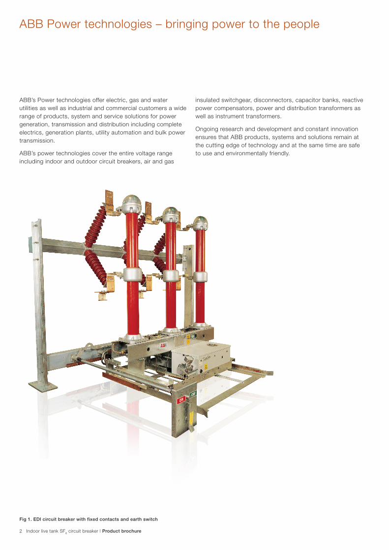
Fig 1. EDI circuit breaker with fixed contacts and earth switch

Product brochure | Indoor live tank SF6 circuit breaker 3
SF6 circuit breaker EDI SK with AutopufferTM
EDI SK is a live tank SF6 AutopufferTM indoor circuit breaker in the voltage range of 36-84kV with rated breaking current up to 31.5kA.
The 3-pole circuit breaker is operated by springs for opening and closing. The springs are situated in the operating mechanism. The circuit breaker together with the operating mechanism and the truck carriage forms a complete withdrawable unit for indoor installation.
Main features and advantagesThe EDI SK circuit breaker is based on the latest developments in arc research and meets varied customer demands, offering the following advantages:
– Restrike free interruption of capacitive currents on account of high inherent di-electric strength of SF6 gas and optimised contact movement
– Low over-voltages when switching inductive currents as a result of optimum quenching at current zero
– High di-electric strength even at atmospheric pressure due to wide contact gap
– Compact design
– Low operating energy requirement, resulting in reduced mechanical stress and low reaction forces on the foundation
– Low noise level – suitable for installation in residential areas
– Easy installation and commissioning. Each circuit breaker is pre-tested and adjusted using an indoor fixture (switchgear cell) in the workshop. No adjustments are necessary at site
– Low weight, easy to move between switchgear cells
– Multiple plug-in contact for the operating circuits
– Ground frame (the ground frame and the multi-plug contact can be delivered in advance in order to minimise installation and commissioning time)
DesignThe circuit breaker pole includes the breaking unit, the polymeric supporting insulator and the pole linkage housing. The three poles of the breaker are mounted on a common supporting frame. The operating mechanism is arranged in front of the breaker. The breaker poles have a common SF6 gas system. The system is filled with SF6 gas at a pressure of 0.7 Mpa (abs) at a temperature of +200C for an operating temperature range of 400C to –300C.
High operating reliability and service life of SF6 circuit breaker is achieved by maintaining the SF6 gas pressure and neutralising the effects of moisture and decomposed products in the gas.
This is achieved by:
– O-rings of nitrile rubber used for sealing purpose
– Each breaking unit is provided with an absorber, which absorbs the moisture and gaseous decomposed products
– To monitor the density of SF6 gas, the circuit breaker is provided with a density monitor common for all the three poles. The density monitor consists of a temperature independent pressure switch
– Temperature dependent pressure variations of SF6 gas are compensated by hermetically sealed reference gas volume. An alarm signal is triggered when the pressure drops due to leakage
Breaker carriage– The motion of the breaker can be carried out by motor or
hand-crank operation
Mechanical and electrical interlocking– Closing operation is blocked during circuit breaker truck
motion
– Truck motion is blocked with the circuit breaker in closed position
Operating mechanism type FSA 1The circuit breaker has a motor charged spring operating mechanism which is installed in a splash proof corrosion protected housing.
Optional equipmentFixed contact and earth switch arrangement in the circuit breaker cell including support beams and insulator. Please refer to Fig. 4 & 5.
Options– EDI SK for fixed installation
– EDI SK with insulator sheds

Breaker pole
4 Indoor live tank SF6 circuit breaker | Product brochure
Fig. 2
Sectional view of a circuit breaker pole:
1. Upper connection flange2. Stationary arcing contact3. Nozzle4. Moving arcing contact5. Stationary continuous current contact6. Moving continuous current contact7. Breaking unit insulator8. Lower connection flange9. Support insulator10. Operating insulator11. Pole linkage housing
Breaker carriage
Fig. 3. The motion of the circuit breaker can be carried out by motor or hand-crank operation
Fig. 4. Fixed contact with earth switch arrangement (optional)

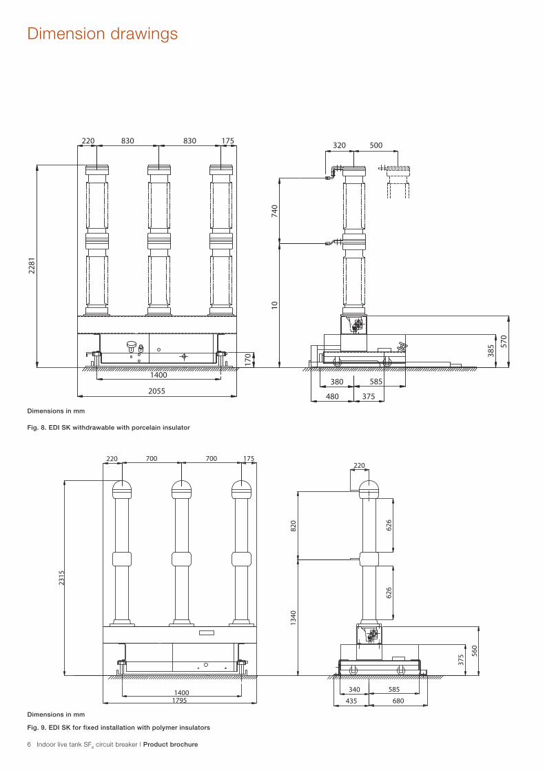
Dimension drawings
Product brochure | Indoor live tank SF6 circuit breaker 5
Fig. 6. Dimensions of the fixed contact arrangement
Fig. 7. EDI SK withdrawable with polymer insulator
* Other values on request.
740
==
727
40
105
500
200
200
760 *) 700 700 760 *)
2920
Dimensions in mm
Dimensions in mm
740
10
375
380
830830220 175
2281
1400
2055
170
570
385
585
480
500320
6 Indoor live tank SF6 circuit breaker | Product brochure
Dimension drawings
Fig. 8. EDI SK withdrawable with porcelain insulator
Fig. 9. EDI SK for fixed installation with polymer insulators
Dimensions in mm
Dimensions in mm
Product brochure | Indoor live tank SF6 circuit breaker 7
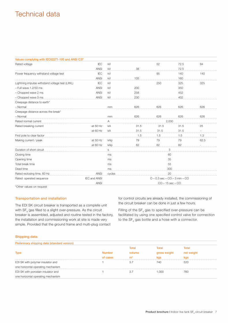
Transportation and installation
The EDI SK circuit breaker is transported as a complete unit with SF6 gas filled to a slight over-pressure. As the circuit breaker is assembled, adjusted and routine tested in the factory, the installation and commissioning work at site is made very simple. Provided that the ground frame and multi-plug contact
for control circuits are already installed, the commissioning of the circuit breaker can be done in just a few hours.
Filling of the SF6 gas to specified over-pressure can be facilitated by using one specified control valve for connection to the SF6 gas bottle and a hose with a connector.
Preliminary shipping data (standard version)
Total Total Total
Type Number volume gross weight net weight
of cases m3 kgs kgs
EDI SK with polymer insulator and 1 3.7 740 520
one horizontal operating mechanism
EDI SK with porcelain insulator and 1 3.7 1,000 760
one horizontal operating mechanism
Shipping data
Technical data
Values complying with IEC62271-100 and ANSI C37
Rated voltage IEC kV 52 72.5 84
ANSI kV 38 72.5
Power frequency withstand voltage test IEC kV 95 140 140
ANSI kV 105 160
Lightning impulse withstand voltage test (LIWL) IEC kV 250 325 325
– Full wave 1.2/50 ms ANSI kV 200 350
– Chopped wave 2 ms ANSI kV 258 452
– Chopped wave 3 ms ANSI kV 230 402
Creepage distance to earth*
– Normal mm 626 626 626 626
Creepage distance across the break*
– Normal mm 626 626 626 626
Rated normal current A 2,000
Rated breaking current at 50 Hz kA 31.5 31.5 31.5 25
at 60 Hz kA 31.5 31.5 31.5 -
First pole to clear factor 1.5 1.5 1.5 1.3
Making current / peak at 50 Hz kAp 79 79 79 62.5
at 60 Hz kAp 82 82 82 -
Duration of short circuit s 3
Closing time ms 60
Opening time ms 35
Total break time ms 55
Dead time ms 300
Rated reclosing time, 60 Hz ANSI cycles 20
Rated operated sequence IEC and ANSI O – 0.3 sec – CO – 3 min – CO
ANSI CO – 15 sec – CO*Other values on request
Contact us
1HY
B80
0001
-002
Rev
.A
© C
opyr
ight
200
9 A
BB
. A
ll rig
hts
rese
rved
.Note: The information in this document is subject to alteration without prior notice and should not be regarded as an undertaking from ABB. ABB takes no responsibility for errors that can occur in the documentation and is not responsible for damage incurred due to the misuse of this document.
We reserve the right to make technical changes or modify the contents of this document as required.
ABB LimitedHigh Voltage Products Maneja, Vadodara 390 013, India Phone: +91-265-2642141 Fax: +91-265-2638918
www.abb.co.in