indoor unit outdoor unit asu9rls3y aou9rls3 asu12rls3y
TRANSCRIPT

SPLIT TYPEROOM AIR CONDITIONERWALL MOUNTED TYPE
CONTENTSSPECIFICATIONS. . . . . . . . . . . . . . . . . . .1
DIMENSIONS . . . . . . . . . . . . . . . . . . . . . . 2
REFRIGERANT SYSTEM DIAGRAM. . . .3
CIRCUIT DIAGRAM. . . . . . . . . . . . . . . . . 4
ERROR DETECTION . . . . . . . . . . . . . . . .
5PCB CIRCUIT DIAGRAM . . . . . . . . . . . . .
7
PARTS (INDOOR UNIT) . . . . . . . . . . . . . .9
PARTS (OUTDOOR UNIT) . . . . . . . . . . .15
18ACCESSORIES . . . . . . . . . . . . . . . . . . .
Indoor unit Outdoor unit
ASU9RLS3Y
ASU12RLS3Y
AOU9RLS3
AOU12RLS3

SPECIFICATIONS
TYPE Cooling and heating inverter
INDOOR UNIT ASU9RLS3Y
OUTDOOR UNIT AOU9RLS3
COOLING CAPACITY 9,000 Btu/h 2.64 kW
HEATING CAPACITY 12,000 Btu/h 3.52 kW
POWER SOURCE 208/230 V
FREQUENCY 60 Hz
RUNNINGCURRENT
MAXIMUMCURRENT
2.5 A
3.3 A
INPUT WATTS0.50 kW
0.66 kW
EER Cooling 18.0 Btu/Wh
COP Heating
Cooling
Heating
Cooling
Heating
Cooling
Heating
18.2 Btu/Wh
MOISTURE REMOVAL
AIR CIRCULATION HIGH
9.4 A
10.9 A
2.6 Pts/h 1.2 L/h
ASU12RLS3Y
AOU12RLS3
12,000 Btu/h 3.52 kW
16,000 Btu/h 4.69 kW
3.8 A
4.7 A
0.79 kW
1.01 kW
15.2 Btu/Wh
15.8 Btu/Wh
2.7 Pts/h 1.3 L/h
489 CFM 830 m3/h
FAN MOTORPOWER SOURCE 208/230 V
High
INDOOR UNITCooling
Medium
Low
Quiet
High
INDOOR UNITHeating
Medium
Low
Quiet
High
Medium
Low
Quiet
1,100 r.p.m.
940 r.p.m.
820 r.p.m.
600 r.p.m.
1,100 r.p.m.
940 r.p.m.
820 r.p.m.
600 r.p.m.
OUTDOOR UNIT Heating
OUTDOOR UNIT Cooling
780 r.p.m.
720 r.p.m.
ELECTRICAL DATA
INDOOR UNITCooling
High
Medium
Low
Quiet
INDOOR UNITHeating
OUTDOOR UNIT Heating
NOISE LEVEL42 dB
37 dB
32 dB
23 dB
41 dB
35 dB
31 dB
23 dB
47 dB
OUTDOOR UNIT Cooling 42 dB
47 dB
43 dB
2016.03.28 1
COMPRESSOR TYPEHermetic type, 4 pole, Single phase,
DC inverter motor, Rotary
DISCRIMINATION
PRECHARGED REFRIGERANT
REFRIGERANT TYPE R410A
WEIGHT (with oil)
COMPRESSOR AND REFRIGERANT
Pipe length 49 ft. 15mFULL CHARGE 66 ft. 20m
MAXIMUM PIPING HEIGHT 49 ft. 15m
ADDITIONAL CHARGE 0.22 oz/ft 20 g/m
WEIGHTINDOOR UNIT Net / Shipping
Net / ShippingOUTDOOR UNIT 84 lb. / 93 lb. 38 kg / 42 kg
INDOOR UNIT H x W x D
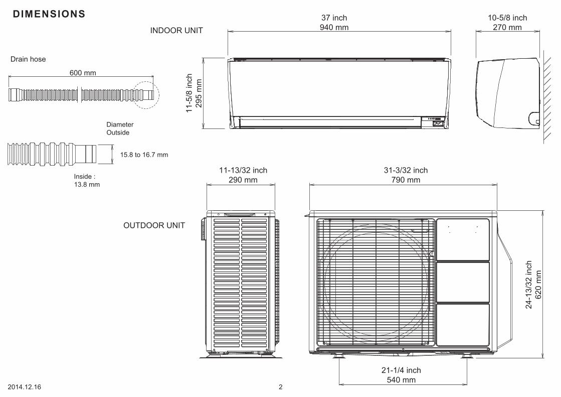
H x W x DOUTDOOR UNIT 24-1/2 x 31-3/32 x 11-13/32 inch620 x 790 x 290 mm
DIMENSIONS
808-884-80
20 lb. 8 oz. 9.3 kg
2 lb. 14 oz. 1,300 g
2 lb. 14 oz. 1,300 g
3 lb. 1 oz. 1,400 g
11-5/8 x 37 x 10-5/8 inch295 x 940 x 270 mm
31 lb. / 37 lb. 14 kg / 17 kg
DIMENSIONS
11-5
/8 in
ch29
5 m
m
10-5/8 inch270 mm
37 inch940 mm
2014.12.16 2
INDOOR UNIT
15.8 to 16.7 mm
Drain hose
DiameterOutside
Inside :13.8 mm
600 mm
OUTDOOR UNIT
11-13/32 inch290 mm
31-3/32 inch790 mm
21-1/4 inch540 mm
24-1
3/32
inch
620
mm

REFRIGERANTSYSTEM DIAGRAM
Refrigerant directionCoolingHeating
Refrigerant pipe diameterLiquid : 1/4" (6.35 mm)Gas : 3/8" (9.52 mm)
2-Way valve
Strainer
Strainer
3-Way valve
Muffler
Accumulator
Muffler
4-Way valveExpansion valve
Heat exchanger(indoor unit)
Heat exchanger(outdoor unit)
Compressor
2015.01.06 3
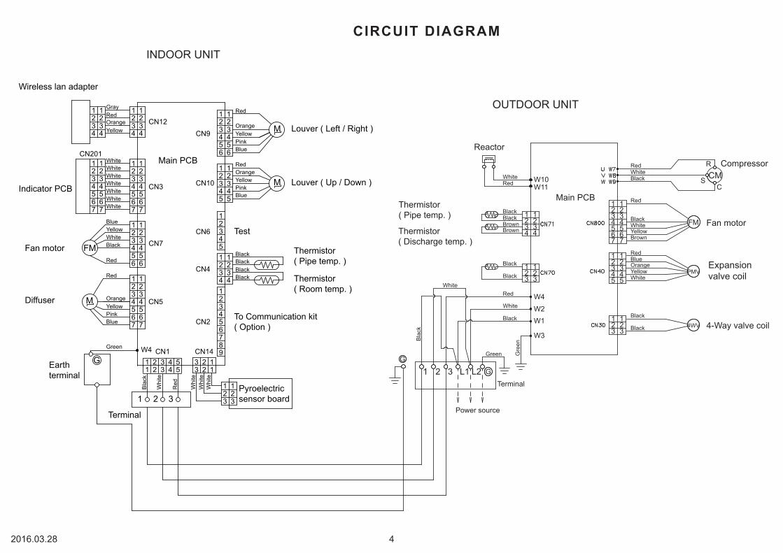
Fan motor
Red
BlackWhiteYellowBrown
RedBlueOrangeYellowWhite
Black
Black
RedWhiteBlack
Main PCB
Reactor
BrownBlackBlack
Brown
WhiteRed
Black
Black
Red
White
Black
Green
White
Gre
en
Bla
ck
1234567
1234567
W10
12345
12345
123
123
123
1234
123
123
S
R
CCM
Compressor
Expansionvalve coil
4-Way valve coil
Thermistor( Pipe temp. )
Thermistor( Discharge temp. )
4
W11
W4
W2W1
W3
G
G
Terminal
Power source
FM
PMV
4WV
L2L1321
Louver ( Left / Right )
Louver ( Up / Down )
Thermistor( Pipe temp. )
Thermistor( Room temp. )
To Communication kit( Option )
Terminal
Pyroelectricsensor board
GEarthterminal
M
FM
Indicator PCB
Wireless lan adapter
Fan motor
Diffuser
M
M
Test
1 2 3
123456789
CN201
CN2
CN3
CN4
CN12
CN6CN7
CN9
CN10
1234567
CN1W4
1234567
CN14
CN5
123456
123456
1234567
1234567
1234
1234
1234
1234
1234567
1234567
123456
123456
12345
12345
123451234
1234
123
123
1 2 3 4 51 2 3 4 5
3 2 13 2 1
OrangeYellowPinkBlue
Red
Red
BlackWhiteYellowBlue
WhiteWhiteWhiteWhiteWhiteWhiteWhite
YellowOrangeRedGray
OrangeRed
YellowPinkBlue
BluePinkYellowOrange
Red
BlackBlack
BlackBlack
Green
Whi
te
Whi
te
Whi
teW
hite
Red
Bla
ck
Main PCB
2016.03.28 4
INDOOR UNIT
OUTDOOR UNIT
CIRCUIT DIAGRAM

YELLOW
ORANGE
RED
GRAY
WHITE
RED
BLACK
YELLOW
BLUE
WHITE
WHITE
WHITE
WHITE
WHITE
WHITE
WHITE
WHITE
WHITE
WHITE
WHITE
WHITE
WHITE
WHITE
WHITE
WHITE
WHITE
YELLOW
PINK
BLUE
ORANGE
RED
RED
ORANGE
YELLOW
PINK
BLUE
RED
ORANGE
YELLOW
PINK
BLUE
BLACK
BLACK
BLACK
BLACK
1
2
3
4
5
6
7
12
3
4
5
6
1
2
3
4
5
1
2
3
4
1
2
3
4
5
6
7
1
2
3
4
5
1
2
3
4
5
6
7
1
2
3
9
8
7
6
5
4
3
2
1
9
8
7
6
5
4
3
2
1
1
2
3
6
5
4
3
2
1
4
3
2
1
4
3
2
1
1 2 3 4 5
CN12013485-1
orB3 ( 5.0 ) B-XASK-1-A
W4
CN4B04B-PLIRK-1
CN10B05B-PLISK-1
CN9B06B-PLIRK-1
CN5B07B-PLISK-1
CN3SZT15-07WS
CN6B5B-PH-K-S
CN201S7B-PH-K-S
BLACK
WHITE
RED
TERMINAL
CN12B04B-PASK-1 (LF) (SN)
CN7B5 ( 6-5 ) B-XNISK-A-1WHITE
CN14B03B-PLISK-1WHITE
CN2B7 ( 9-7.8 ) B-PLISKWHITE
CND01B7 ( 9-7.8 ) B-PLISK
B03B-PLISK-1
S04B-PASK-1 (LF) (SN)
3
2
1
OUTDOOR UNIT
M
M
M
THERMISTOR ( PIPE TEMP. )
THERMISTOR ( ROOM TEMP. )
LOUVER ( UP / DOWN )
LOUVER ( RIGHT / LEFT )
DIFFUSER
TEST
EARTH TERMINAL
FAN MOTOR F M
CONTROL UNITASU9RLS3Y : EZ-0150AHSE
PCB CIRCUIT DIAGRAM
ASU12RLS3Y : EZ-0150BHSE
MAIN PCBASU9RLS3Y : K15CA-1500HSE-C1ASU12RLS3Y : K15CA-1501HSE-C1
INDICATOR PCBK12JZ-1200HSE-D01
TO COMMUNICATION KIT( OPTION )
PYROELECTRICSENSOR BOARD
WIRELESSLAN ADAPTER
DC340V
DC5V
DC15V
DC340V
DC13V
DC5V
DC13V
DC13V
DC13V
DC5V
A
A
A
D
A
D
CN4Thermistor Characteristics.
Thermistor ( Pipe temp. ) 176.0 k 62.9 k 39.6 k1.1 V 2.2 V 2.8 V
(20 68 )°F (30 86 )°F( 0 32 )°FThermistorTemperature
Thermistor ( Room temp. ) 33.6 k 12.5 k 8.0 k1.1 V 2.2 V 2.8 V
CN7 DC Fan motor
654321
Pin No. Terminalcode
Vm
GNDVccVspPG
Function of terminal
Revolution pulse outputSpeed control voltage inputControl power voltage input
GND
Motor power voltage input
Lead wirecolor
Red
Black
WhiteYellowBlue
2016.01.19 5

W11B
W10B
W5 W6
TERMINALHP-T3036-9-L6S
FRAME FRAME
W1B
W2B
W4B
W3B
W7B U
W8B V
W9B W
UL1015AWG14BLACK
UL1015AWG14WHITE
UL1015AWG20RED
UL1015AWG16GREEN
UL1015AWG14ORANGE
UL3271AWG14WHITE
UL3271AWG14RED
UL3271AWG16WHITE
UL3271AWG16RED
UL3271AWG16BLACK
RED
WHITE
BLACK
BLACK
BLACK
BLACK
BLACK
RED
WHITE
YELLOW
BROWN
RED
BLUE
ORANGE
YELLOW
WHITE
BLACK
BLACK
BLACK
BLACK
BROWN
BROWN
W103UL1015AWG20BLACK
W100UL1015AWG20WHITE
W102UL1015AWG20BLACK W101
UL1015AWG14BLACK
1
2
3
4
5
6
7
1
2
3
4
5
1
2
3
1
2
3
4
1
2
3
EMI FILTERZCAT2132-1130
1 TURN
EMI FILTERIt is included in a wire.
EMI FILTERZCAT2132-1130
1 TURN
WIRE w/TERMINAL ( CORE )1015#22GREEN
THERMISTOR ( PIPE TEMP. )
THERMISTOR ( DISCHARGE TEMP. )
THERMISTOR ( OUTDOOR TEMP. )
SERIAL
N
L
POWER SOURCEAC208-230V60Hz
POWER EARTH
1
2
3
L
NCN30
B2P3-VH-B-CBLACK
CN800B5 ( 7-2.3 ) B-XASK-1-A
WHITE
CN40B05B-PLISK-1
WHITE
CN71B04B-PASK-1WHITE
CN70B03B-PASK-1WHITE
4-WAY VALVE COIL
COMPRESSOR
DC FAN MOTOR
EXPANSION VALVE COIL
FM
PMV
CM
TO INDOOR UNIT
MAIN PCBAOU9RLS3 : K10CT-1402HUE-C1AOU12RLS3 : K10CT-1404HUE-C1
CN71Thermistor Characteristics.
Thermistor ( Pipe temp. ) 16.1 k 6.0 k 3.8 k1.1 V 2.2 V 2.8 V
(20 68 )°F (30 86 )°F( 0 32 )°FThermistorTemperature
Thermistor ( Discharge temp. ) 168.6 k 62.6 k 40.0 k0.4 V 0.9 V 1.2 V
CN70Thermistor Characteristics.
Thermistor ( Outdoor temp. ) 35.2 k 12.6 k 8.0 k2.6 V 3.8 V 4.1 V
(20 68 )°F (30 86 )°F( 0 32 )°FThermistorTemperature
CN800 DC Fan Motor
1
3456
Pin No. Terminalcode
Vm
GNDVccVspFG
Function of terminal
Revolution pulse outputSpeed control voltage inputControl power voltage input
GND
Motor power voltage input
Lead wirecolor
Red
Black
WhiteYellowBrown
2
7
1(Red) - 2(Blue)1(Red) - 3(Orange)1(Red) - 4(Yellow) 1(Red) - 5(White)
CN40 Expansion Valve Coil
46.0
Recommended Drive ConditionUnipolar Drive, 1-2 Phase Excitation.
Coil resistance
(20 68 )°F
U-VV-WU-W
CompressorWinding Resistance
1.408
(25 77 )°F
DC Resistance 2085 (20 10% 68 )°F
REACTOR15mH 10A
DC Resistance 292.71m (25 77 )°F
AC208-230V( ON )
DC12V
DC340V
DC15V
2016.01.20 6
INVERTER ASSEMBLYAOU9RLS3 : EZ-014PHUEAOU12RLS3 : EZ-014SHUE
If you use a wireless remote control, the lampon the photo detector unit will output error codesby way of blinking patterns.If you use a wired remote control, error codeswill appear on the remote control display.See the lamp blinking patterns and error codesin the table.An error display is displayed only during operation.
Indoor unit lamps Wiredremotecontrol
DescriptionOPERATION
(green)TIMER
(orange)ECONOMY
(green)
Indoor unit lamps Wiredremotecontrol
DescriptionOPERATION
(green)TIMER
(orange)ECONOMY
(green)
(1) (1) Serial communication error
(1) (2) Wired remote controlcommunication error
(1) (5) Check run unfinished
(2) (2) Indoor unit capacity error
(2) (3) Combination error
(3) (2) Indoor unit PCB model information error
(3) (5) Manual auto switch error
(4) (1) Room temp. sensor error
(4) (2) Indoor unit Heat Ex. Middle temp. sensor error
(5) (1) Indoor unit fan motor error
(5) (15) Indoor unit error
Intake grill error
(6) (2)Outdoor unit main PCB model information error or communication error
(6) (3) Inverter error
(6) (4) Active filter error,PFC circuit error
(6) (5) Trip terminal L error
(6) (10) Display PCB microcomputers communication error
(7) (1) Discharge temp. sensor error
Compressor temp. sensor error
(7) (3) Outdoor unit Heat Ex. liquid temp. sensor error
(7) (4) Outdoor temp. sensor error
(7) (5) Suction Gas temp. sensor error
(7) (6) 2-way valve temp. sensor error• 3-way valve temp. sensor error•
(7) (7) Heat sink temp. sensor error
(8) (2)Sub-cool Heat Ex. gas inlet • temp. sensor errorSub-cool Heat Ex. gas outlet • temp. sensor error
(8) (3) Liquid pipe temp. sensor error
(8) (4) Current sensor error
(8) (6)Discharge pressure sensor error• Suction pressure sensor error• High pressure switch error•
(9) (4) Trip detection
(9) (5) Compressor rotor position detection error
(9) (7) Outdoor unit fan motor error
(9) (9) 4-way valve error
(10) (1) Discharge temp. error
(10) (3) Compressor temp. error
(10) (4) High pressure error
(10) (5) Low pressure error
Branch boxes error[flexible multi]
Wired remote control display (Option)If an error occurs, the following display will be shown.(“Er” will appear in the set room temperature display.)
Error code
ERROR DETECTION
2016.03.28 7
: 0.5s ON / 0.5s OFF
: 0.1s ON / 0.1s OFF
( ) : Number of flashingINDOOR UNITREMOTE CONTROL
(13) (2)
(2) (1)Unit number or Refrigerant circuitaddress setting error[Simultaneous Multi]
(2) (7) Primary unit, secondary unit set-uperror [Simultaneous Multi]
(2) (4)
•Connection unit number error (indoor secondary unit) [Simultaneous Multi]•Connection unit number error (indoor unit or branch unit) [Flexible Multi]
(5) (3) Drain pump error
(5) (7) Damper error
(5) (8)
(7) (2)
OPERATION indicator lamp (green)TIMER indicator lamp (orange)
ECONOMY indicator lamp (green)

LED
OUTDOOR UNIT
0.5 second on / 0.5 second off
on
0.1 second on / 0.1 second off
2.0 second on / 2.0 second off
IPM overcurrent protection
Discharge temperature abnormal
Thermistor abnormal
CT abnormal
0.1 second on / 2.0 second off
5.0 second on / 5.0 second off
ERROR
Compressor location abnormal
Fan abnormal
2011.08.04 8
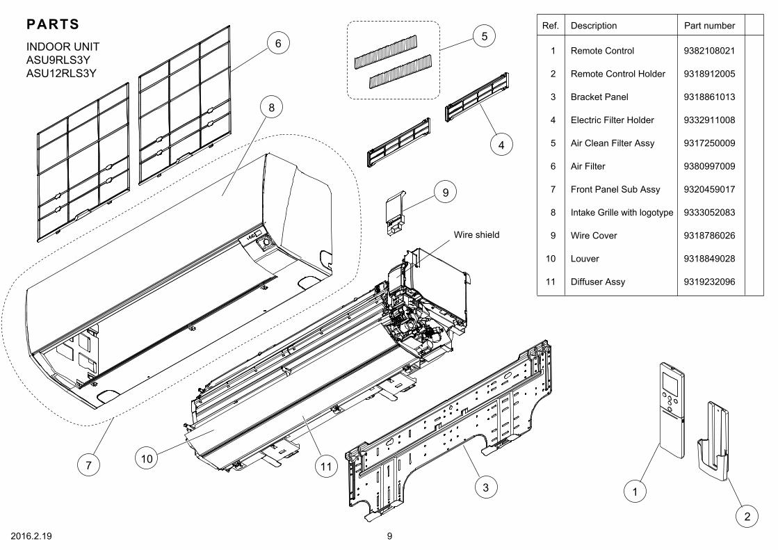
PARTSINDOOR UNITASU9RLS3YASU12RLS3Y
2016.2.19 9
6
9
10
8 Intake Grille with logotype 9333052083
7 Front Panel Sub Assy 9320459017
Bracket Panel
4
Wire Cover 9318786026Wire shield
Electric Filter Holder 9332911008
5 Air Clean Filter Assy 9317250009
1 Remote Control 9382108021
2
3
Remote Control Holder 9318912005
9318861013
Ref. Description Part number
Air Filter 9380997009
Louver 9318849028
11 Diffuser Assy 9319232096
1
2
9
5
4
3
6
8
7 1011

INDOOR UNITASU9RLS3YASU12RLS3YControl box
102016.03.28
Terminal 990072002524
Control Box22
Cover shield
21 9318757033Control Cover
9380996026
Main PCB (ASU9RLS3Y) 971036801123
Main PCB (ASU12RLS3Y) 971036802823
26 Room Thermistor Holder 9379930000
Ref. Description Part number
25
28 Wireless LAN Adapter 9382167004
27 Thermistor Assy 9900627003
Display Assy 9709642023
27
23
22
28
21
26
25
24

INDOOR UNITASU9RLS3YASU12RLS3YEvaporatorFan
Fan Motor 9603253028
Crossflow Fan Assy 9315024060
Bearing C Assy 9306628017
37
32
Evaporator Total Assy 931925459331
Casing Total Assy 9319171319
33
34
Motor Cover 9316568006
Motor Cover 9316601000
35
36
Ref. Description Part number
112016.02.16
37
34
33
31
32
35
36

41
42
43
INDOOR UNITASU9RLS3YASU12RLS3YCasing total assy
12
41 Outlet Cover Assy 9319776002
43
42
Casing Assy 9319172217
- Cable Guide 9321517006
Motor Case Assy 9319173085
Ref. Description Part number
2016.02.16

53
51
54
56
58
57
61
52
5252
55
60
59
INDOOR UNITASU9RLS3YASU12RLS3YMotor case assy
13Louver Gear B 9316616004
52
55
Step Motor (R&L)
60
Link A 9317507004
53
Step Motor (Louver)56
Step Motor (Diffuser)
9900384135
9900384142
9900139230
59
Gear A 9309994003
54
Louver Gear A 9318749007
51
Gear Cover A 9318748000
Gear Cover B 9318750003
Louver Link Holder 9319150000
Motor Case 9318746020
61
57
58
Ref. Description Part number
2016.02.16

80
77
74
75
73
79
71
72
78
76
INDOOR UNITASU9RLS3YASU12RLS3YCasing assy
14
Fan Guard 9320458003
79
80
76
Drain Hose Assy 9316904019
Pipe Bracket 931874302978
Drain Cap 9316177017
71
Casing Cover B 9318862003
74
Casing Cover F 9382222000
Casing Cover L 9318830002
Casing Cover R 931883100975
R and L Louver Assy 9319229027
Casing 9318840025
77
72
73
Ref. Description Part number
2016.03.26

3
4
5
13
11
12
1
7
6
2
OUTDOOR UNIT
PARTS
2016.03.28 15
2 Top Panel Assy 9318464023
3 Front Panel Assy 9318463026
1 Protective Net
5 Cabinet Left Assy 9318461015
4 Emblem
Valve bracket
Motor bracket11 Propeller Fan 9313808013
8 Base Assy 9316885066
13 Reactor Assy 9900611019
Separator assy
12 Fan Motor 9602724017
Ref. Description Part number
8 6
9317903011
Switch Cover 9317692021
7 Cabinet Right Assy 9316044050
9331640008
Drain Assy 93030290229
Drain Cap 31316602430210
910

OUTDOOR UNIT
2014.12.18 16
Ref. Description Part number
28 Outdoor Thermistor 9900544010
Terminalbracket
Conduit bracket
24 Terminal 9900016081
23 Terminal Cover Assy 9317898034
29 Thermistor Assy 9900614027
Sealed panel
Inverter case
Invertercase cover
Main PCB (AOU9RLS3)21 9709221426
Main PCB (AOU12RLS3)21 9709221440
22 PCB Holder 9313074029
27 Heat Sink B 9314090011
26 Heat Sink A 9314410017
25 Semiconductor Accessory 9705840010
24
23
2127
26
22
28
29
25

OUTDOOR UNIT
2014.12.19 17
32 Compressor Assy 9317117005
34 3-way Valve Sub Assy 9317109000
37 Pulse Motor Valve Assy 9332368048
4-way Valve Assy 9315311092
36 Solenoid 9970110047
31 Condenser Total Assy 9317089135
38 Expansion Valve Coil 9970095030
35
33 2-way Valve Assy 9332371000
Ref. Description Part number
32
31
33
37
34
38
35
36

Name and Shape Part number
9310519004
0600185541Battery (penlight)
Cloth tape
ACCESSORIES
2016.03.28 18
INDOOR UNIT
Remote Control 9382108021
Remote ControlHolder
9318912005
Bracket Panel
9318861013
Name and Shape Part number
0700076046
9317250009
9332911008Filter holder
Air cleaningfilter assy
Tapping screw(M4 x 25 mm)
Tapping screw(M3 x 12 mm)
0700019036
Name and Shape Part number
9303029022
OUTDOOR UNIT
Drain assy
313166024302Drain cap

1602G4490