induction machine
TRANSCRIPT

INDUCTION MACHINES
Induction machines: works on electromagnetism. We can equalize to transformer
Induction machines of two type-
1. Squirrel cage
2. Slipring
SQUIRREL CAGE SLIPRING
1. Rotor consists of bars which are shorted at the ends with the help of end rings.
2. As permanently shorted, external resistance cannot be added.
3. Slip rings and brushes are not there. 4. 5% of induction motors in industry use slip
ring rotor. 5. Moderate torque we get 6. Used for lifts ,cranes, elevators,
compressors ,etc.
1. Rotor consists of a 3∅ winding similarly to the stator winding.
2. Resistance can be added externally. 3. Slip rings and brushes are there. 4. 95% of induction motors use this type of
rotor. 5. High torque we get be adding external
resistance. 6. Used for drilling machines, fans, blazers,
water pumps, grinders, printing machines, etc.
SPEED OF ROTATING MAGNETIC FIELD (R M F):-
For standard frequency whatever speed of R.M.F results is called as synchronous speed in case of
induction motors
It is denoted as Ns
Ns=120𝑓
𝑝
Where, f=supply frequency
P=number of poles
This is the speed with which R.M.F rotates in space/air gap.
Let use see how to change direction of rotation of R.M.F.

∅T -> clockwise direction ∅T -> Anticlockwise direction
SLIP OF INDUCTION MOTOR
We know that rotor rotates in the same direction as that of R.M.F. but in steady state obtains as speed less
than the synchronous speed. The diff. between two speed i.e., synchronous speed (Ns) and rotor speed(N)
is called slip speed. This slip is generally expressed as the % of synchronous speed.
i.e., s=𝑁𝑠−𝑁
𝑁𝑠-absolute slip
%s=𝑁𝑠−𝑁
𝑁𝑠*100 % slip
In terms of slip actual speed of motor (N) can be expressed as, N=Ns(1-s)
At stator motor is at rest and hence its speed N is zero
i.e., s=1 at start
This is the max. Value of slip s possible for induction motor which occur at start while s=0 gives us N=Ns
which is not possible for an induction motor. So slip of induction motor cannot be zero under any
circumstances.
Practically motor operates in the slip range of 0.01 to 0.05 i.e., 1% to 5%. The slip corresponding to full
load speed of the motor is called as full load slip.
EFFECTS OF SLIP ON ROTOR PARMETERS:-
Slip affects the frequency of rotor induced emf due to this some other rotor parameters also get affected.
Let us study the effect of slip on the following parameters.
1. Rotor frequency
2. Mag. Of rotor induced emf.
3. Rotor reactance
4. Rotor power factor

5. Rotor current
EFFECT ON FREQUENCY
W k t , Ns=120𝑓
𝑝….1
In running condition of motor mag. Of induced emf decreases so as its frequency .the rotor is wound
for same no. of poles as that of stator i.e. p. if fr is the frequency of rotor induced emf in running
condition at slip speed Ns-N then there exists a fixed relation between (Ns-N),fr and p similarly to
above eq. so we can write rotor in running condition.
(Ns-N)= 120𝑓𝑟
𝑝………..rotor poles =stator poles=p
Equation 2/1
𝑁𝑠−𝑁
𝑁𝑠=
120fr/p
120f/p but
𝑁𝑠−𝑁
𝑁𝑠 =s
S=𝑓𝑟
𝑓
Fr=sf
EFFECT ON MAG. OF RATOR INDUCED EMF
W k t
E2=rotor induced emf at standstill
E2r=rotor induced emf in running condition
E2∝Ns E2r∝Ns-N
𝐸2𝑟
𝐸2=
𝑁𝑠−𝑁
𝑁𝑠 but,
𝑁𝑠−𝑁
𝑁= 𝑠
𝐸2𝑟 = 𝑠𝐸2
EFFECT ON ROTOR RESIS. AND REACTANCE
R2=rotor resistance per phase on standstill and running
X2=rotor reactance per phase on standstill
X2=2𝜋𝑓𝐿2 during running, X2r=2𝜋frL2=2𝜋sfL2
X2r=sX2
Z2r=√𝑅22 + (𝑠𝑋2)2 Ω/ph =R2+jX2r=R2+jsX2 Ω/ph

EFFECT ON ROTOR POWER FACTOR
COS∅=𝑅2
𝑍2=
𝑅2
√𝑅22+(𝑆𝑋2)2
EFFECT ON ROTOR CURRENT
I2=𝐸2 𝑝𝑒𝑟 𝑝ℎ𝑎𝑠𝑒
𝑍2 𝑝𝑒𝑟 𝑝ℎ𝑎𝑠𝑒𝐴
I2=𝐸2
√𝑅22+𝑋22A
I2r=𝐸2𝑟
𝑍2𝑟=
𝑠𝐸2
√𝑅22+(𝑠𝑋2)2
INDUCTION AND SYNCHRONOUS MACHINE
UNIT-1
3∅ INDUCTION MOTOR
VISUALIZATION OF A 3 PHASE INDUCTION MOTOR AS A GENERALIZED
TRANSFORMER WITH A ROTATING SEC. AND ITS EQUIVALENT CIRCUIT
The induction motor can be visualized as transformer. The transformer works on the principle of
electromagnetic induction the induction motor also works on electromagnetic induction. The energy
transfer from stator to rotor of induction motor takes place entirely with the help of a flux mutually
linking the two. Thus stator acts as primary. And rotor act as secondary. When induction motor is
treated as transformer
K = 𝑟𝑜𝑡𝑜𝑟 𝑡𝑢𝑟𝑛𝑠
𝑠𝑡𝑎𝑡𝑜𝑟 𝑡𝑢𝑟𝑛𝑠 =
𝐸2
𝐸1
Where, E2=rotor induced emf per phase at standstill
E1=induced voltage in stator per phase
In running condition the E2 will become E2r which is equal to sE2. Where s is slip of induction motor
i.e., s = 𝑁𝑠−𝑁
𝑁𝑠

Where,
E2r = rotor induced emf in running condition per phase
R2 = rotor resistance per phase
X2r = rotor reactance per phase in running condition
R1 = stator resistance per phase
X1 = stator reactance per phase
When induction motor is on no load it draws a current from the supply to produce the flux in air gap
and supply iron losses
i.e., Io Ic = active component which supplies no load losses
Im = magnetizing component which set up flux incore and airgap
R0 = 𝑉1
𝐼𝑐
X0 = 𝑉1
𝐼𝑚
I0 = Ic + Im
The equivalent circuit of induction motor can be represented as

Where I2r=𝐸2𝑟
𝑍2𝑟=
𝑠𝐸2
√𝑅22+(𝑠𝑋2)2
As load on the motor changes , the motor speed changes thus slip changes.AS slip changes the
reactance X2r changes .hence X2r=sX2 is shown variable
I2r = 𝐸2
√(𝑅2
𝑠)2+𝑋22
So it can be assumed that equivalent rotor circuit in the running condition has fixed reactance X2,
fixed voltage E2 but a variable resistance R2/s , as indicated in the above equation
Now 𝑅2
𝑠= 𝑅2 +
𝑅2
𝑠− 𝑅2 = 𝑅2 + 𝑅2 (
1
𝑠− 1) = 𝑅2 + 𝑅2(
1−𝑠
𝑠)
Variable resistance R2/s has two components
1. Rotor resistance R2 itself which represents copper loss
2. R2*(1-s)/s which represents load resistance RL. So it is electrical equivalent of mechanical load
on the motor.
So rotor equivalent circuit can be show as,
Let us obtain equation circuit referred to stator :-
Transfer all the rotor parameters to stator
K = 𝐸2
𝐸1 = transformation ratio

E2’ = 𝐸2
𝑘
I2r’ = KI2r = 𝐾𝑠𝐸2
√𝑅22+(𝑠𝑋2)2
X2’ = 𝑋2
𝐾2 = reflected rotor reactance
R2’ = 𝑅2
𝐾2 = reflected rotor resistance
R2’ = 𝑅𝐿
𝐾2 =
𝑅2
𝐾2(
1−𝑠
𝑠) = 𝑅2′(
1−𝑠
𝑠) = reflected mechanical load
DIFFERENT KINDS OF POWER LOSSES
The various power losses in an induction machine can be classified as,
1. Constant losses
2. Variable losses
CONTANT LOSSES
These can be classified as
1. Core loss
2. Mechanical loss
Core losses occurs in stator core and rotor core. These are also called iron losses. These losses include
eddy current and hysteresis loss. The eddy current losses are minimized by using laminated
construction while hysteresis losses are minimized by selecting high grade silicon steal as the material
for stator and rotor.
The mechanical losses include frictional losses at the bearing s and windage losses in air gap.
VARIABLE LOSSES
This include the copper losses in stator and rotor winding due to current flowing in the winding as
current changes as load changes , these losses are said to be variable losses
Stator cu loss=3I22R
Rotor cu loss=3I2r2R2
Where,
R1=stator resistance

R2=rotor resistance
I2=stator current
I2r=rotor current at that particular load
Power flow in an induction machines
Pout=useful power or shaft power
Pout=Pm-mechanical losses
Pm=P2-Pc
Where Pc=3I2r2R2
P2=Pm-stator losses(core+cu)
Pin=net input
Pin =√3𝑉𝐼𝑐𝑜𝑠∅
Rotor efficiency =𝑟𝑜𝑡𝑜𝑟 𝑜𝑢𝑡𝑝𝑢𝑡
𝑟𝑜𝑡𝑜𝑟 𝑖𝑛𝑝𝑢𝑡=
𝑔𝑟𝑎𝑠𝑠 𝑚𝑒𝑐ℎ. 𝑝𝑜𝑤𝑒𝑟 𝑑𝑒𝑣𝑒𝑙𝑜𝑝𝑒𝑑
𝑟𝑜𝑡𝑜𝑟 𝑖𝑛𝑝𝑢𝑡=
𝑃𝑚
𝑃2
Net motor efficiency=𝑛𝑒𝑡 𝑜𝑢𝑡𝑝𝑢𝑡 𝑎𝑡 𝑠ℎ𝑎𝑓𝑡
𝑛𝑒𝑡 𝑒𝑙𝑒𝑐𝑡𝑟𝑖𝑐 𝑖𝑛𝑝𝑢𝑡 𝑡𝑜 𝑚𝑜𝑡𝑜𝑟=
𝑃𝑜𝑢𝑡
𝑃𝑖𝑛
Relation between P2,PC and Pm(derivation is not required)
P2:Pc:Pm=1:s:1-s 𝑃𝑐
𝑃𝑚=
𝑠
1−𝑠,𝑃2
𝑃𝑐=
1
𝑠,
𝑃2
𝑃𝑚=
1
1−𝑠
Phasor diagram of induction motor on no load and loaded condition

At no load condition
The current I1 and I2r values are less compare with loaded condition of the machine
At loaded condition
The current I1 and I2r values are more compare with no load condition of the machine
In phasor diagram ǿ is reference line .due to flux(ǿ),the E1 will induced by 90o lagging the E2r will be
in phase with E1 with less value.I2r will lag E2r/E1 by ǿ2r. the I2rR2 in phase with I2r and I2rX2r reading
the resistance drop by 90o, to get E2r.Im is in phase with ǿ while Ic is at 90o leading with ǿ.if we add Ic
and Im weget Io. Adding I2r’ and Io we get I1. The v1 is obtained by adding -E1,I1R1 and I1X1. Angle
between V1 and I1 is ǿ1
Torque equation of induction machine
Its depends on
1. The part of rotating magnetic field which reacts with rotor and is responsible to produce induced
emf in rotor
2. The mag. Of rotor current in running condition
3. The power factor of the rotor circuit in running condition
Mathematical relation can be expressed as,
T 𝛼 ∅ I2r cos ∅2r
Where, ∅= flux responsible to produce induced emf
I2r= rotor running current
Cos ∅2r=running power factor of rotor
∅𝛼𝐸1
Where 𝐸2
𝐸1= 𝑘
E2 𝛼 ∅
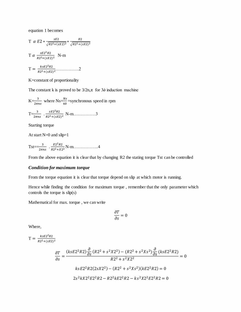
equation 1 becomes
T 𝛼 𝐸2 ∗𝑠𝐸2
√𝑅22+(𝑠𝑋2)2∗
𝑅2
√𝑅22+(𝑠𝑋2)2
T 𝛼 𝑠𝐸22𝑅2
𝑅22+(𝑠𝑋2)2 N-m
T = 𝑘𝑠𝐸22𝑅2
𝑅22+(𝑠𝑋2)2…………….2
K=constant of proportionality
The constant k is proved to be 3/2nsπ for 3ǿ induction machine
K=3
2𝜋𝑛𝑠 where Ns=
𝑁𝑠
60 =synchronous speed in rpm
T=3
2𝜋𝑛𝑠 .
𝑠𝐸22𝑅2
𝑅22+(𝑠𝑋2)2 N-m……………3
Starting torque
At start N=0 and slip=1
Tst==3
2𝜋𝑛𝑠 .
𝐸22𝑅2
𝑅22+𝑋22 N-m……………..4
From the above equation it is clear that by changing R2 the stating torque Tst can be controlled
Condition for maximum torque
From the torque equation it is clear that torque depend on slip at which motor is running.
Hence while finding the condition for maximum torque , remember that the only parameter which
controls the torque is slip(s)
Mathematical for max. torque , we can write
𝜕𝑇
𝜕𝑠= 0
Where,
T = 𝑘𝑠𝐸22𝑅2
𝑅22+(𝑠𝑋2)2
𝜕𝑇
𝜕𝑠=
(𝑘𝑠𝐸22𝑅2)𝜕𝜕𝑠
(𝑅22 + 𝑠2𝑋22) − (𝑅22 + 𝑠2𝑋𝑠2)𝜕𝜕𝑠
(𝑘𝑠𝐸22𝑅2)
𝑅22 + 𝑠2𝑋22 = 0
𝑘𝑠𝐸22𝑅2(2𝑠𝑋22) − (𝑅22 + 𝑠2𝑋𝑠2)(𝑘𝐸22𝑅2) = 0
2𝑠2𝑘𝑋22𝐸22𝑅2 − 𝑅22𝑘𝐸22𝑅2 − 𝑘𝑠2𝑋22𝐸22𝑅2 = 0

𝑘𝑠2𝑋22𝐸22𝑅2 − 𝑅22𝑘𝐸22𝑅2 = 0
𝑠2𝑋22 − 𝑅22 = 0
𝑠2 =𝑅22
𝑋22
𝑠 =𝑅2
𝑋2
This is the slip at which the torque is max. and denoted as Sm
Sm=R2/X2
It is the ratio of standstill per phase values of resi. And reactance of rotor
When torque produced by the induction machine is at its max
Maq. Of max torque =Tm=𝑘𝑆𝑚𝐸22𝑅2
𝑅22+(𝑆𝑚𝑋2)2=
𝑘(𝑅2
𝑋2)𝐸22𝑅2
𝑅22+((𝑅2
𝑋2)𝑋2)2
=𝑘𝐸22
2𝑋2 N-m
Power equation from equivalent circuit
Pin=input power =3V1I1cos∅
V1=stator voltage/ph
I1=current drown by stator/ph
cos∅=power cu loss = 3(I2r’)2R2’
P2=Pc/s=3(I2r’)2R2’/s

Pm=P2-Pc=(3(I2r’)2R2’/s)- 3(I2r’)
2R2’=3(I2r’)2R2’(
1−𝑠
𝑠)
T=torque developed
T=Pm/w=3(I2r’)2R2’(
1−𝑠
𝑠)
2𝜋𝑁
60
Where N=speed of motor
T=3(I2r’)2R2’/𝑠
2𝜋𝑁
60
=9.55*((3(I2r’)2R2’/s)/Ns) N-m
And I2r’=𝑉1
(𝑅𝑖𝑒+𝑅𝑙′)+𝑗(𝑋𝑖𝑒)
Rl’=𝑅2′(1−𝑠)
𝑠
I2r’=𝑉1
√(𝑅𝑖𝑒+𝑅𝑙′)2+(𝑋𝑖𝑒)2