industrial training report on diesel locomotive technology report 2015 (lucknow)
TRANSCRIPT

DIESEL LOCOMOTIVE WORKSHOP
NORTHERN RAILWAY,CHARBAGH
LUCKNOW
A
INDUSTRIAL TRAINING REPORT
ON
DIESEL LOCOMOTIVE TECHNOLOGY
SUBMITTED TO - SUBMITTED BY -
Mr. Annand Dutta SSE/ DSL Shail KrishnaMr. K . K . Nigam SSE/DSL B .Tech (Mechanical)

Diesel Workshop M.I.E.T. Meerut.Lucknow Charbagh

WORK INSTRUCTIONVERSION : 1.0
Copy No. 04
Copy Holder : SSE ,Radiator & Hood
AS COMPLIANCE TO ISO – 9001 : 2000
This work instruction is for use of Northern Railway Diesel POH Shop Charbagh Lucknow .
© Copyright 2001, Northern Railway Diesel POH Shops. Charbagh , Lucknow -226005 .All rights reserved. No part of this document may be reproduced transmitted or translated in any for or by any means, electronic, mechanical, manual, photo copying, optical or otherwise without prior written permission of the Deputy Chief Mechanical Engineer (Diesel), Northern Railway , Diesel POH Shops,Charbagh, Lucknow .Note to the copy holders – In the event of transfer, the controlledCopies should be returned to the issuing authority.
NORTHERN RAILWAY DIESEL POH SHOPCHARBAGH,
LUCKNOW

ACKNOWLEDGEMENT
I take this opportunity my sincere thanks and deep gratitude to H.C. BHATIA (HEAD OF MECHANICAL DEPARTMENT) all these people who extended their whole hearted co-operation and helped me in completing this project successfully.
Frist of all I would like to thanks all the S.S.E. and J.E of the all section for creating opportunities to undertake me in this esteemed organization. Special thanks to all the department for all the help and guidance extended to me by them in every stage during my training. His inspiring suggestions and timely guidance enabled me to perceive the various aspects of the project in the new light.
In all I found a congenial work environment in DIESEL LOCOMOTIVE WORKSHOP, CHARBAGH LUCKNOW and this completion of the project will mark a new beginning for me in the coming days.

CONTENTS
INTRODUCTION OF INDIAN RAILWAY DIESEL LOCOMOTIVE WORKSHOP .CHARBAGH DIESEL ELECTRIC LOCOMOTIVE WORKING MECHANISIM IMPORTANT COMPONENTS OF LOCOMOTIVES
a) POWER PACKb) FUEL SECTIONc) LUBE OIL CONTROL SECTION
i. FUEL INJECTION PUMP (FIP)ii. INJECTORS
d) TURBO SUPER CHARGING (TSC)e) BRAKESf) COMPRESSOR / EXPRESSORg) GOVERNORSh) TRACTION MOTERi) BOGIEj) GENERATORk) RADIATORl) ENGINE SECTIONm) CROSS HEAD
i. INLET AND EXHAUST VALVE FAILURE ANALYSIS
a) MAGNAFLUX LABb) ULTRASONIC TESTc) ZYGLO TESTd) RDP TEST

HISTORY OF INDIAN RAILWAYS
FOUNDED : April 16, 1853, Amalgamation on 1947
Head Quarters : New Delhi
Area covered : India
Industry : Railways and locomotives
Types of track : Broad gauge, Narrow gauge, Wide gauge
Area Network : 63,140 km
Owner : Government of India Website : https//www.indianrailways.gov.in/

INTRODUCTION
OF
INDIAN RAILWAY
Indian railway is the state-owned railway company of India. It comes under the Ministry of Railway. Indian Railways has one of the largest and busiest rail networks in the world, transporting over 18 million passengers and more than 2 million tons of freight daily .Its revenue is 107.66 billion. It is the world’s largest commercial₹ employer, with more than 1.4 million employees. It operates rail transport on 6,909 stations over a total route length of more than 63,327 kilometers (39,350miles). The fleet of Indian Railway includes over 200,000 (freight) wagons. 50.000 coaches and 8,000 locomotives. It also owns locomotive and coach production facilities. It was founded in 1853 under the East India Company.
Indian Railways is administered by the railway Board. Indian Railway is divided into 16 zones. Each zone railway is made up of a certain number of divisions. There are six manufacturing plants of the Indian Railways is about 108,805km (67,608 mi) while the total route length of the network is 63,4565km (39,453mi) . About 40% of the total track km is electrified & almost all electrified sections use 25,000 V AC .Indian Railways uses four rail track gauges
Indian Railways operates about 9,000 passenger trains and transports 18 million passengers daily. Indian Railways makes 70% of its revenues and most of its profits form the freight sector, and uses these profits to cross-subsidies the loss-making passenger sector. The Rajdhani Express and Shatabdi Express are the fastest trains of India.

DIESEL LOCOMOTIVE WORKSHOP
CHARBAGH, LUCKNOW
LUCKNOW DIESEL WORKSHOP (Fig-1)
Diesel locomotive workshop is an industrial-technical setup, where repair and maintenance works of diesel locomotives is carried out, so as to keep the loco working properly. It contributes to increase .The operational life of diesel locomotives and tries

to minimize the line failures. The technical manpower of a workshop also increases the efficiency of the loco and remedies the failures of loco.
The workshop consists of the infrastructure to berth, dismantle, repair and test the loco and subsystems. In the workshop working is heavily based on the manual methods of doing the maintenance job and very less automation processes are used in workshop especially in India.
The diesel workshop usually has –
o Berth and platforms for loco maintenance.o P.O.H , I.O.H , S.Ro Pits for under frame maintenance.o Heavy lift cranes and lifting jacks.o Fuel storage and lube oil storage. Water treatment plant and testing labs etc.o Overhauling, Repairing, Maintenance section.o Machine shop and welding facilities.
DIESEL LOCOMOTIVE WORKSHOP CHARBAGH, LUCKNOW of NORTHERN RAILWAY is located in LUCKNOW. The workshop was established on 22nd April 1857. It was initially planned to home 75 locomotives. The workshop cater the needs of Northern Railway. This workshop mainly provides locomotives. To run the mail, goods, and passenger services. No doubt the reliability, safety through preventive and predictive maintenance is high priority of the workshop. To meet out the quality standard workshop has taken various steps and obtaining of the ISO-9001-200O AND ISO 14001 OHS AS CERTIFICATION is among of them. The Diesel workshop is equipped with modem machines and plant required for maintenance of Diesel Locomotives and has an attached store deport .To provide pollution free atmosphere. Diesel workshop has constructed Effluent Treatment Plant. The morale of supervisors and staff of the workshop, is very high and whole workshop works like a well-knit team.
OVER VIEW
INCEPTION 22nd April 1857
Present Holding 147 Locomotives
19 WDM2
37 WDM3A
08 WDM3D
11 WDG3A
46 WDP1
26 WDP3A
Accreditation ISO-9001-2000 & ISO 14001
Covered area of 10858 sq.mt Workshop
Total area of 1,10,000 sq.mtWorkshop
Staff strength sanction - 1357 On roll - 1201
Berthing capacity 9 loco per month

DIESEL ELECTRIC LOCOMOTIVE
PARTS OF THE LOCO (Fig-2)
o DRIVER CABINE o GENERATOR ROOMo FUEL TANKo AIR RESERVOIRS o BATTERIS (8V)o DISCo DYNAMO WITH ALTERNATORo TRACTION MOTERo BLOWERo GEAR & PENIONS ASSEMBLYo POWER PACKo AUXILARY ALTERNATORo MAIN ALTERNATORo CYLINDER HEADo CROSS HEAD
o AFTER COOLING COREo JUCTION BOXo BOGIE (2 SETS)(3AXLE OR 2 AXLE)o TURBO SUPER CHARGERo RADIATORo RADIATOR FANo SNAD BOX
Diesel electric loco were introduced firstly in United States in 1924 & have become the most widely used type of loco.
It was introduction for first time in India in 1958.
Diesel electric loco has electric drive in from of traction motors driving the axis an controlled with electronic controls.it differs from electric loco principally in that it has its own generating station instead of being connected to a remote generating stations through overhead wires.
The generating station consists of a large diesel engine coupled to DC generator that provides to traction motors. These motors drive the wheels.

LOCO- BRIEF DATA
WEIGHT OF COMPLETE LOCO - 123 TONS
WEIGHT OF LOLO BADY IS - 73 TONS
WEIGHT OF COMPLETE BOGIE IS - 25 TONS
LOAD EXERTED PER AXL E IS - 20.5 TONS
WEIGHT OF TRACTION MOTOR IS - 3.80 TONS
WHEEL SET WITH GEARS IS APPRPOX. - 2.15 TONS
COST OF ONE LOCO - 12 TO 14 crore (EMD) 7 TO 8 crore (ALCO)
FUEL CONSUMPTION :
I. FUEL LOAD -540 lit/hr. II. IDLE LOAD -40 lit/hr.
III. PICKP VALUE -18 TO 19 lit
MAX. SPEED 160 Km/hr.
DIA OF WHEEL - 1092mm
WHEEL TO WHEEL DISTANCE - 1596.5mm
LENGTH OF UNDER FRAME - 19962 mm

Locos, except the older steam ones, have classification codes that identify them. This code is of the form
WDG5A “[gauge] [motive power] [load] [series] [sub type or horse power]”

CLASSIFICATIONS OF CODES-
o WDM - Broad Diesel Mixed
o WDP - Broad Diesel Passenger
o WDG - Broad Diesel Goods
o WDS - Broad Diesel Shunting
o WCDS - Broad Converted Diesel Shunting


WORKING MECHANISIM
OPERATION –
There are four strokes in power section. Which are discussed below –
1. SUCTION STROKE
Suction stroke start when the piston is at the TDC and about to move downwards. The inlet valve is open at this time and the exhaust valve is closed. Due to the suction created by the motion of this piston towards the BDC, the charge consisting of air is drawn into the cylinder. When the piston reaches the BDC (Bottom Dead Centre) the suction stroke ends and the Intel valve closes.
2. COMPRESSION STROKE
The charge taken into the cylinder during the suction stroke is compressed by the return stroke of the piston. During this stroke both inlet & exhaust valve are in closed position.

The air which fills the entre cylinder volume is now compressed into the clearance volume.
3. POWER STROKE
Fuel injection starts nearly at the end of the compression stroke. The rate of injection is such that combustion maintains the pressure constant in spite of the piston movement on its expansion stroke increasing the volume. Heat is assumed to have been added at constant pressure. After the injection of fuel is combustion expands. Both the valves remain closed during the expansion stroke.
4. EXHAUST STROKE
The piston travelling from BDC to TDC pushed out the products of combustion. The exhaust valve is open and the intake valve is closed during this stroke.

POWER PACK
.
The work of the power pack is to do the fitting work of the head on the loco. They take out head from the engine and assembled it again on the loco. In the power pack section the assembly of piston and connecting rod is done. The thorough checking of piston is done. In this section. The piston is send for zyglo test then it is checked whether the piston is seizing or not.
There are two types of piston used modified and unmodified .In modified piston and piston head is made up of steel, the piston skirt is made up of aluminum. Unmodified piston is totally made up of steel only .the weight of the assembly is of 90 kg. There generally 5

rings used in the cylinder, first 3 are compression ring next 2 are oil rings. The first one is made up of steel and has square face. The second one is also of steel and has tapered face. The third one is of C.I. and is fuel efficient taper face. The fourth and fifth are also of C.I and are called oil scrapper rings.
PARTS OF THE POWER PACK -
o EXHAUST MANIFOLDo WATER CHANNELo PGEV GOVERNORo CRANK CASE MOTERo CYLINDER (16max / 12min)o PISTONo FUEL OIL INJECTORo ROCKER ARMo YOKEo LUBE OIL HEADER PIPEo L PIPE o S PIPEo F PIPEo CAM SHAFTo CRANK SHAFTo CROSS HEADo CROSS PIPEo FUEL INJUCTION PUMPo FIP COVERo FUEL OIL BENZOo LUBE OIL ENZOo GEAR CASEo CYLINDER HEAD o INLET & EXHAUST VAULVEo TURBO SUPER CHARGER

o AFTER COOLING COREo OVER SPEED TR IPo HOUSINGo OIL SLEEVE RINGo WATER PUMPo LUBE OIL PUMPo OIL SLEEVEo DRAINE PIPEo FUEL CONTROOLING SHAFTo SUMP o HEADERo DRAIN PIPE o DRAIN PLUGEo BLOCKo HEAD / ENGINE BLOCKo GENERATORo FUEL OIL BENZOo PUNCH ROADo OVER SPEED TRIP (O.S.T)o CONTROL SHAFTo T. C SAPORTo WATER CHANELo WATER RISERo WATER JUMPERo BALOWo COUPPILINGo CRANK SHAFT VIBRATORo PUMP PLATE

FUEL SECTION

LUBE OIL CONTROL SECTION


FUEL INJECTION PUMP (FIP)

INJECTORS
Introduction
In unit injector (UI) and unit pump (UP) systems, each engine cylinder is served by a separate injection pumping element or injection pump in close proximity to the cylinder. Unit pump (UP) systems enable short high pressure fuel lines by locating the pump close to the injector. Combining the pumping element and the injector into one assembly as in unit injector (UI) systems, allows these lines to be eliminated altogether. The elimination—or length reduction—of high pressure fuel lines in the UI/UP injection systems results in two benefits:
Reduction of line dynamics problems: line dynamics difficulties in unit injectors/unit pump systems are less troublesome than in their pump-line-nozzle (P-L-N) counterparts. The possibility of wave superposition—which troubled the P-L-N systems by causing after-injections and contributing to
injection delays—is greatly reduced. However, it should be mentioned that line dynamics problems generated within the narrow passages of unit injectors may still modulate the rate of injection.
Higher injection pressure: the UI system has traditionally had the highest injection pressure capability among all types of injection system. In the early 2000s, UI systems had pressure capabilities of 200 MPa, compared to 160 MPa in common rail systems. Since then, UI/UP system peak injection pressures have risen to as high 250 MPa for some 2007 model year applications.
With regards to fuel pressure, it should be noted that common rail fuel injection system pressures have risen as well and in some systems have reached or exceeded the pressures available from UI/UP systems. While there is no technical reason keeping UI/UP pressures from rising even further, engine manufacturers are increasingly using common rail systems in applications traditionally dominated by UI/UP systems. For this reason, UI/UP systems will likely see little evolution beyond their current peak pressures of about 250 MPa.

Both the UI and UP systems are driven from the engine camshaft. In one common mechanical system design, fuel control was typically achieved by rotation of the pumping element (plunger) in the same way as is done in P-L-N systems. With the introduction of electronics to diesel engines, electronic unit injector (EUI) and electronic unit pump (EUP) systems were developed. These employ an electromagnetically operated spill valve for fuel control.
Due to the presence of fuel lines, the unit pump system can be classified as a variant of the P-L-N injection system. However, the design of unit pump and unit injector systems is often similar, making it convenient to discuss these systems together. In fact, some manufacturers offer their injection systems in both UI and UP versions (compare Figure 4 and Figure 11).
The commercial application of unit injectors started in the 1930s on Winton (a GM subsidiary) and GM diesel engines. Winton continued to supply engines to the Electro-Motive Corporation (EMC), while GM transferred diesel engine production to its Detroit Diesel Division. The Detroit Diesel Corporation’s two-stroke engine line is one of the better known applications of unit injector technology. From the 1930s to the mid-1980s, Detroit Diesel used a mechanical unit injector design. In 1985, Detroit Diesel’s Series 92 two-stroke engine became the first heavy-duty diesel engine to adopt electronically controlled unit injection [Bara 1990]. Since this introduction of electronic control, unit injectors continued to evolve to higher levels of sophistication. The evolution for light-duty and heavy-duty applications followed different paths.
Possibly the most advanced design of unit injector for light-duty applications is the PPD injector produced briefly by Volkswagen Mechatronic (a joint-venture between Volkswagen and Siemens VDO) starting in 2004 for model year 2006 Euro 4 applications. This injector used a piezoelectric actuator and was capable of up to 2 pilot injections and 2 secondary injections in addition to the main injection event. However, it came at a time when common rail systems had already taken hold in light-duty applications and were quickly gaining ground. The PPD injector could not compete with common rail systems and was phased-out soon after its launch. Starting in 2007, it was replaced with common rail for Euro 5 applications. Common rail systems have since become the preferred choice for light-duty applications and unit injectors are quickly disappearing from new engine designs.
For heavy-duty applications, electronic unit injectors continued to evolve. The evolution of some of these designs is described in the paper on injection systems in HD engines. The pinnacle of heavy-duty unit injector design is represented by the two-valve designs of Delphi’s E3 and Caterpillar’s MEUI-C injectors for engines meeting US EPA

2007 on-road emission standards. While these advanced unit injector designs have capabilities such as rate shaping and multiple injections, common rail systems for heavy-duty applications have evolved to the point were they are replacing unit injectors in many new engine designs for markets with the most demanding emission standards. To facilitate this switch, fuel injection equipment manufacturers have designed common rail systems that can easily be fitted to engine platforms that were originally designed for unit injector or unit pump systems and thus avoiding the need for a completely new engine design.

TURBO SUPER CHARGING (TSC)
PARTS OF TURBO SUPER CHARGER
o ROTOR ASSEMBLY (TURBINE)o NOZZLE RINGo GAS INLET CASINGo INTERMEDIATE CASINGo BLOWER CASINGo TURBINE BEARINGo BLOWER TEARING

Classification
Superchargers are mechanically, electrically, or hydraulically driven pumps, compressors, or blowers employed to boost the pressure of the charge air in diesel engines or of the intake charge mixture in spark ignited engines. Most superchargers have traditionally been built around positive displacement compressors. However, with the focus to develop improved drives early in the 21st century, there has been a growth in interest in using superchargers based on centrifugal compressors.
Turbochargers are commonly used on truck, car, train, aircraft, and construction equipment engines. They are most often used with Otto cycle and Diesel cycle internal combustion engines. They have also been found useful in automotive fuel cells.
A multitude of device types can be used as superchargers –
The top six devices in the chart are positive displacement, while the centrifugal compressor is classified as an aerodynamic or continuous flow device. Positive displacement devices deliver a specific volume of air per revolution. Since the volumetric efficiency is almost constant, air flow is usually proportional to the supercharger or engine speed. Positive displacement devices can provide high boost pressures without the need for high speed. Therefore, they are well suited for a mechanical connection with the engine, such as through a gearbox or a belt/pulley drive. Each of the particular devices has its
advantages and disadvantages, which determine which supercharger is best suited for a specific application.
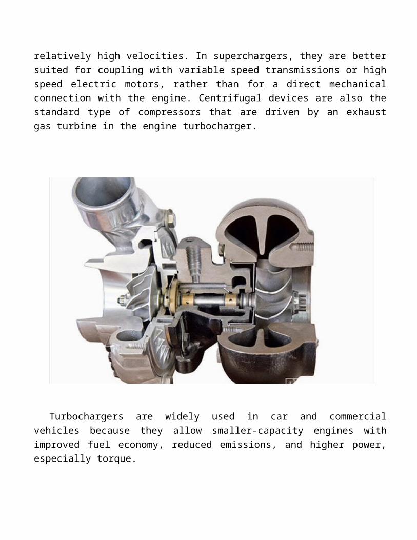
Centrifugal compressors are well suited to deliver high flow volumes at relatively low pressure ratios. With the boost pressure generally proportional to the square of the supercharger speed, centrifugal compressors must operate at relatively high velocities. In superchargers, they are better suited for coupling with variable speed transmissions or high speed electric motors, rather than for a direct mechanical connection with the engine. Centrifugal devices are also the standard type of compressors that are driven by an exhaust gas turbine in the engine turbocharger.
Turbochargers are widely used in car and commercial vehicles because they allow smaller-capacity engines with improved fuel economy, reduced emissions, and higher power, especially torque.

BRAKES
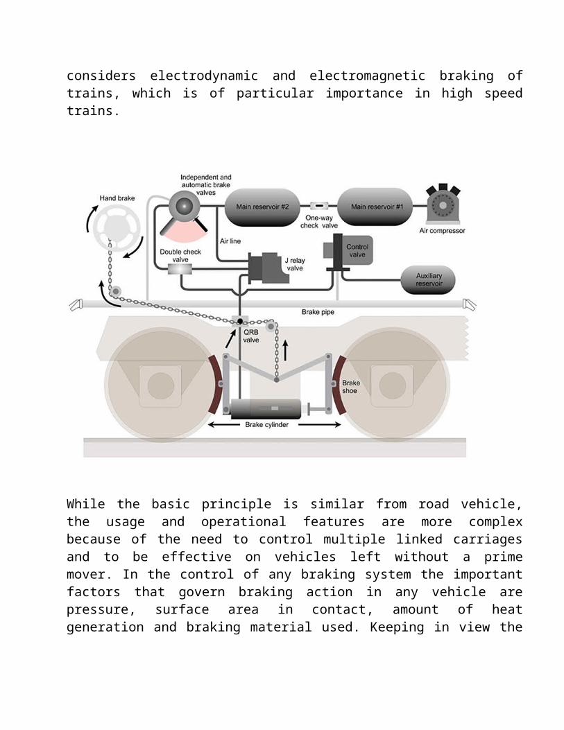
Brake is an essential feature in order to retard and stop the railway vehicle within minimum possible time. This paper presents a discussion about the different braking systems used in railway vehicles. This paper also considers electrodynamic and electromagnetic braking of trains, which is of particular importance in high speed trains.

While the basic principle is similar from road vehicle, the usage and operational features are more complex because of the need to control multiple linked carriages and to be effective on vehicles left without a prime mover. In the control of any braking system the important factors that govern braking action in any vehicle are pressure, surface area in contact, amount of heat generation and braking material used. Keeping in view the safety of human life and physical resources the basic requirements of brake are:
o The brake must be strong enough to stop the vehicle during an emergency with in shortest possible distance.
o There should be no skidding during brake application and driver must have proper control over the vehicle during emergency.
o Effectiveness of brakes should remain constant even on prolonged application or during descending on a down gradient

o Brake must keep the vehicle in a stationary position even when the driver is not present. The brake used in railway vehicles can be classified according to the method of their activation into following categories.
o Pneumatic Brakeo Electrodynamic Brakeo Mechanical Brake
1) D 12) HAND BRAKR
o Electromagnetic Brakeo Pneumatic Brake may be further classifiedo Vacuum Brakeo Compressed air brake
1) SA9 (INDEPENDENT BRAKE)2) A9 (AUTOMATIC BRAKE)3) DYNAMIC BRAKE
SA9 brake valve has three stages . Following different pressure are reduced in different position.
POSITION BRAKE PIPE IN GAUGE (kg/cm2)
Release position 3.0
Application 2.5
Quick release 0.0

A9 brake valve has five stages . Following different pressure are reduced in different position.
POSITION BRAKE PIPE IN GAUGE (kg/cm2)
REDUCTION IN BRAKE PIPE PRESSURE
REDUCTION IN VALVE PIPE VACCUM
Release position 5.0 0.0 55-60
Minimum reduction
4.5 0.5 50-55
Full service 3.5 1.5 25-30
Maximum reduction
2.5 2.5 12-20
Emergency position
0.0 5.0 0-0
On the emergency position the engine becomes idle. When the A9 BRAKE Valve liner in the right direction in the brake. Remain In the released position and when moved toward left/up to the end completely, it emergency position.


COMPRESSOR / EXPRESSOR
A compressor is a device that converts power (using an electric motor, diesel or gasoline engine, etc.) into potential energy stored in pressurized air (i.e., compressed air). By one of several methods, an air compressor forces more and more air into a storage tank, increasing the pressure. When tank pressure reaches its upper limit the air compressor shuts off. The compressed air, then, is held in the tank until called into use. The energy contained in the compressed air can be used for a variety of applications, utilizing the kinetic energy of the air as it is released and the tank depressurizes. When tank pressure reaches its lower limit, the air compressor turns on again and re-pressurizes the tank.

According to the pressure delivered -
1. Low-pressure air compressors (LPACs), which have a discharge pressure of 150 psi or less
2. Medium-pressure compressors, which have a discharge pressure of 151 psi to 1,000 psi
3. High-pressure air compressors (HPACs), which have a discharge pressure above 1,000 psi
According to the design and principle of operation -
1. Rotary screw compressor
2. Turbo compressor
Cooling -
Due to adiabatic heating, air compressors require some method of disposing of waste heat. Generally this is some form of air- or water-cooling, although some (particularly rotary type) compressors may be cooled by oil (that is then in turn air- or water-cooled) and the atmospheric changes also considered during cooling of compressors.
Applications -
To supply high-pressure clean air to fill gas cylinders
To supply moderate-pressure clean air to a submerged surface supplied diver
To supply moderate-pressure clean air for driving some office and school building pneumatic HVAC control system valves
To supply a large amount of moderate-pressure air to power pneumatic tools, such as jackhammers
For filling tires
To produce large volumes of moderate-pressure air for large-scale industrial processes (such as oxidation for petroleum coking or cement plant bag house purge systems).

Most air compressors either are reciprocating piston type, rotary vane or rotary screw. Centrifugal compressors are common in very large applications. There are two main types of air compressor's pumps: oil-lubed and oil-less. The oil-less system has more technical development, but is more expensive, louder and lasts for less time than oil-lubed pumps. The oil-less system also delivers air of better quality.
The most common types of air compressors are: electric or gas/diesel powered compressors. The power of a compressor is measured in HP (Horsepower) and CFM (cubic feet of air per minute). The gallon size of the tank tells you how much compressed air "in reserve" is available. Gas/diesel powered compressors are widely used in remote areas with problematic access to electricity. They are noisy and require ventilation for exhaust gases. Electric powered compressors are widely used in production, workshops and garages with permanent access to electricity. Common workshop/garage compressors are 110-120 Volt or 230-240 Volt. Compressor tank shapes are: "pancake", "twin tank", "horizontal", and "vertical". Depending on a size and purpose compressors can be stationary or portable.
EXPRESSOR –
The combination of exhauster and compressor is called expresser. It is provided in the expresser room. The main function of expresser is to the compress the air for various purpose and to create vacuum for train brake.
It has one crank shaft and two bearings. One end of the crank shaft is connected to engine .Main crank shaft with fast coupling and other end connected to the extension shaft No.2 with flexible coupling.

DIFFERENT TYPES OF EXPRESSOR -
1) 6CD4U (4 EXHAUSTER & 2 CMPRESSOR)2) KE6 (3 EXHAUSTER & 3 COMPRESSOR)3) KE523 (ONLY COMPRESSOR)

GOVERNORS
THERE ARE TWO TYPES OF GOVERNOR USED IN LOCO WDM-2
1) WOODWARD GOVERNOR or P.G.E.V. GOVERNOR2) M.C.VC GOVERNOR
It is a controlling unit of any Loco, it controls
o FUEL RATEo LOAD (IDEL / FULL SPEED)o SPEEDo SAFETY DEVICES
Auxiliary Devices -
Many auxiliary devices are available for use, either singly in combination for the PGE governor. Some auxiliary equipment may be supplied as original equipment only, and some may be installed in the field. Contact Woodward for information .The following paragraphs give a brief description of some of the auxiliary equipment installed on PGE governors and lists the manuals where detailed information may be obtained. Automatic Safety Shutdown and Alarm .This devices protects the engine in the event of loss of normal lube oil operating pressure. It allows a relatively low minimum oil-pressure level for safe engine operation at idle speed while requiring increasingly higher levels for safe operation at higher speeds. A time-delay feature (adjustable within a range of 15 to 45 seconds or up to 60 seconds with an accumulator) allows the engine to be started without lubricating oil pressure, yet prevents prolonged operation if a safe pressure level is not reached within the preset time. At engine speeds above the first notch, the time delay is normally bypassed so that shutdown is immediate.
A Cooling Water Pressure Failure Shutdown device protects the engine from a drop in the normal operating pressure of the water cooling system. This unit's function is similar to that of the lube-oil-pressure-failure system.
Load Control Override -
This mechanism overrides the normal functioning of the load control system and reduces generator field excitation current during engine start up, wheel slip, or transition.
Manifold Air Pressure Bias Fuel Limiter -
The fuel limiter restricts engine fuel during acceleration as a function of manifold air pressure to ensure more complete combustion, reducing smoke to a minimum, and improving acceleration.
Load Control Device -
The load control device schedules load as a function of speed setting. If actual load is different, the load control device sends a signal to the locomotive excitation control system to increase or decrease excitation. Altitude

Compensator -
The altitude compensator linkage is used with the in-line model (single barrel) "Manifold Air Pressure Bias Fuel Limiter." This linkage compensates for altitude changes by biasing the load-control schedule.
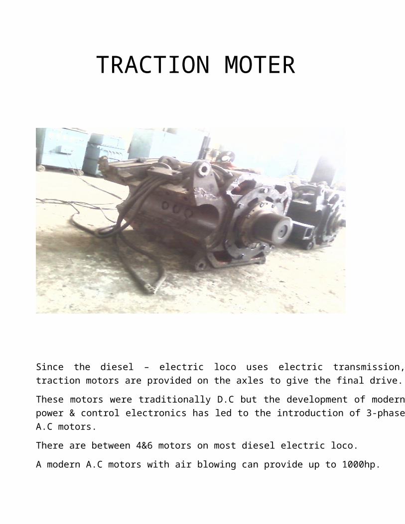
TRACTION MOTER
Since the diesel – electric loco uses electric transmission, traction motors are provided on the axles to give the final drive.
These motors were traditionally D.C but the development of modern power & control electronics has led to the introduction of 3-phase A.C motors.
There are between 4&6 motors on most diesel electric loco.
A modern A.C motors with air blowing can provide up to 1000hp.
PINION/GEAR
The traction motor drives the axle through reduction gear of a range between 3 to 1 (freight) & 4 to 1 (passenger).

BOGIE
Introduction –
o Bogies works as a leg of locomotive.o It bears load of loco U/F, power pack, super structure & other accessories of
loco.o It is very important assembly as per loco running & braking in concern.o Two bogies are used in one loco.o One bogie contain three axle, 6 wheel, 3 traction motors, suspension
arrangement & brake rigging etc. (except Bo-Bo bogie such as WDP1)
IMPORTANT PARTS OF THE BOGIE
o BOGIL FRAME (TRUCK FRAME)o AXILE

o WHEELSo BULL GEARSo SUSPENSION TUBEo AXLE BOXES
o TRACTION MOTERSo BRAKE RIGGING ITEMS (LEVERS)o AIR PIPING

TYPES OF BOGIE -
1) AO bogie - one wheel bogie2) BO bogie - two wheel bogie3) Coco bogie - three wheel bogies

GENERATOR


RADIATOR
Radiator –
As the name suggest, cool down the water temp of engine with some technique.
In the radiator we have the –
CORE-
With copper tubes & fixed both side of the radiator & the water pore from the core. It comes in the contact of the atmosphere air contact to cool the hot water which runs in the copper tubes.

FAN-
A fan is provided to maintain the required air flow is provided to maintain the air flow across the radiator matrix and to bring down temperature of the water .
It fix at the top of the radiator & its works with the relay valve start the fan at three different temp ETS1-68 Ċ , ETS2 – 74 Ċ , ETS3 -91Ċ with three different speed.
When the temperature of the water reaches equal to the give temp then this relay rotate the fan with different speed this the safety device.
FAN E.C.C. (Eddy Clutch Current)

This fan rotated through the transmission of the crank shaft and the connected with the universal shaft.
R.T.T.M. (Rear Truck Motor)Lube oil cooler.
RADIATOR FAN

R.T.T.M. (Position) E.C.C RADIATOR
The purpose of radiator is to reject the coolant heat to the atmospheric air .The cooling effect in radiator is achieved by dispersing the heated coolant into fine stream through the radiator matrix so that small quantity of heat coolant come in contact with large metal surface area so to increase the rate of heat transfer .
TYPES OF RADIATOR :
1) Honey comb block2) Ribbon-cellular 3) Long tube4) Corrugated fin
A. HONEY COMB BLOCKThis type of radiator is provided with circular tubes which cooling air is passed through the tube water is flowing between the tube .
B. RIBBON-CELLULR MATRIX :This consist of a pair of thin metal ribbons soldered together along their edges so as to form a water way running from header tank to collector tank and a zig zag copper ribbon between two water ways acts as air fins .

C. LONG TUBE & FIN TYPES :This types of matrix consist of a series of a series of long tube extending from top to bottom of the radiator and surrounded by metallic fins. Coolant passes through the tube & air passes through the fins around the tube .
D. CORRUGATED FIM TYPE :In this , water tube are made of flattened oval shape section and zig – zag cooper ribbon are used for air flow .

Advantage :
Useful for high output engine . This can be conveniently located wherever required . Fuel consumption of high compression water cooled engine is lower . Higher volumetric efficiency .

CROSS HEAD
INTRODUCTION -

FAILURE ANALYSIS


CONCLUSION
I have completed my training from the DIESEL LOCOMOTIVE WORKSHOP, LUCKNOW .I have observed many shop in the workshop I mainly performed my training in the RADIATOR SECTION.
In the locomotive workshop all the S.S.E & J.E. & SUPERVISIORS of all the shops helped very much. Without his or her supervision I was not able to perform the training in all the workshop. I am very grateful to him.
We have learned too much in the workshop, DIFFERENT TYPE OF WORKSHOP TECHNOLOGY, TESTING OF THE PARTS OF THE LOCOMOTIVE AND THE PROPER FUNCTIONING of the different locomotive part as an AIR BRAKE, LOAD BOX, TURBOSUPERCHGER, EXPRESSOR, POWER PACK, RADIATOR, and AND BOGIE AND FABRICATION OF THE BODY OF LOCOMOTIVE.

REFRENCES
Workshop / Production technology by A .B KHANA
Study material provided by technical training center
Study material provided by A. K SINGH
https://wikimedia.org.in
http://www.woodward.com/ApplicationsLocomotive.aspx
https://en.wikipedia.org/wiki/Turbocharger
https://www.dieselnet.com/tech/diesel_fi_ui.php
https://www.IRFCA.CO.IN