inf5050 introduction to optical...
TRANSCRIPT


TRANSPACKET
Background
• M.Sc. Physics/electronics UIO. • Ph.D. Telecommunication NTNU • 10 years at Telenor R&D optical network • Adjunct associate professor at NTNU • Founder of TransPacket AS

TRANSPACKET
Scope of lecture
• Give an introduction to optical networking • Highlight main motivation for optical
networks • Point to the hottest research topics

TRANSPACKET
Historic Internet traffic trends
1
1) Prediction made in 2000; the last years have not been that fast
What do you think will make the traffic grow in the future?

TRANSPACKET
Strong growth of mobile and Internet
• Video and mobile traffic 2014 to 2019: 6X/10X
• Video and mobile have strict quality demands to the network

TRANSPACKET
Propagation through fibre • Lightpulses are reflected in the core when
hitting the cladding => approximately zero loss
Andreas Kimsås, Optiske Nett

TRANSPACKET
19. desember 2013
Transmission capacity in optical fiber (lab)
7
D.J. Richardson et al., Nature Photonics, v. 7 p. 354, 2013
100Tbit/s

TRANSPACKET
19. desember 2013
Transmission capacity in optical fiber (lab)
8
D.J. Richardson et al., Nature Photonics, v. 7 p. 354, 2013
Multicore fibre is next? Current record is: Pb/s HOT research!

TRANSPACKET
Fibre-cables are spanning the world
Source: RAMPART

TRANSPACKET
UNINETT "network:"Optical "
TRANSPORT"network"Example"
What is Metro?"And Access?

TRANSPACKET
What is a long distance?
• 100 m? • 10 Km? • 100 Km? • 1000 Km?

TRANSPACKET
What is a long distance?
• 100 m? – LAN
• 10 Km? – Access network
• 100 km? – Metro network
• 1000 Km? – Transport network – E.g. subsea-cables

TRANSPACKET
Access trends Fibre

TRANSPACKET
Paper for student presentation
• “PON in Adolescence: From TDMA to WDM-PON”, Grobe, Klaus et al.; IEEE Applications & Practice: Topics in optical communications, January 2008, Pages: 26-34

TRANSPACKET
Fibre-optical transmission system
Transmitter (Laser+
modulator)
Receiver (photodiode +
aplifier Fibre
Attenuation: Some light being absorbed
Dispersion:
Time Time
Pulse Spreading
Illustration: Lucent Technologies
Light of speed wavelength dependent

TRANSPACKET
Wavelength division multiplexing
• Enables large capacity increase in optical fibers • Makes optical networking possible/interresting
Earlier 11 11
11 1111 1144 44
11
22
33
44
11
22
33
44
Tidligere utbygging
RegeneratorTerminalFiber
Før: 1 kanal pr fiber
Optisk forsterker
MultiplekserDemultiplekser
2,5 Gb/s =30000
Opptil20 000 000
WDM: 4-128 kanaler
pr fiberNåværende utbygging
Wavelength Divis ion Multiplexing(WDM), mangedobler kapas itet i fiber
Electronic/electrooptical
Now
Optical amplifier
WDM: 4-128 channels pr fiber
1 channel pr fiber
Up to

TRANSPACKET
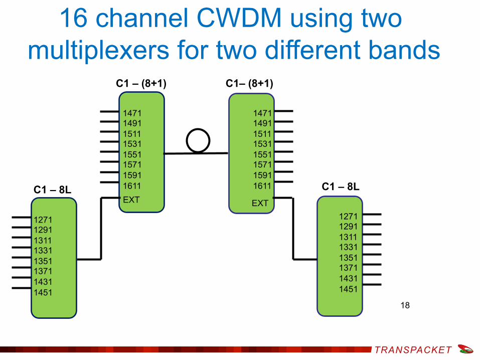
Course WDM • Cheap technology with limited capacity and distance • Typically maximum 16 channels and no amplifiers
0
0,1
0,2
0,3
0,4
0,5
1200 1300 1400 1500 1600
Wavelength (nm)
Loss
(dB
/km
)
2 dB/km G.652 G.652C
1271-1451 nm 1471-1611 nm
TRANSPACKET
16 channel CWDM using two multiplexers for two different bands
18
EXT
EXT
C1 – (8+1) C1– (8+1)
C1 – 8L C1 – 8L
1471 1491 1511 1531 1551 1571 1591 1611
1471 1491 1511 1531 1551 1571 1591 1611
1271 1291 1311 1331 1351 1371 1431 1451
1271 1291 1311 1331 1351 1371 1431 1451

TRANSPACKET
Long distance optical system
• Attenuation must be compensated – Regeneration – Attenuation
• Dispersion must be compensated – Dispersion compensation employing fibre – Electronic compensation

TRANSPACKET
fibre-optical transmission at longer distances
Transmitter (Laser+
modulator)
Receiver (photodiode +
aplifier Fibre
Must be compensated in long distance transmission:
Attenuation: Some light being absorbed
Dispersion:
Time Time
Pulse Spreading
Illustration: Lucent Technologies
Light of speed wavelength dependent

TRANSPACKET
Long distance fibre-optical transmission
Transmitter (Laser+
modulator)
Receiver (photodiode +
amplifier) Fibre
To be compensated:
Dispersion:
Time Time
Pulse Spreading
Illustration: Lucent Technologies
Speed of light is wavelength dependent
EDFA
TRANSPACKET
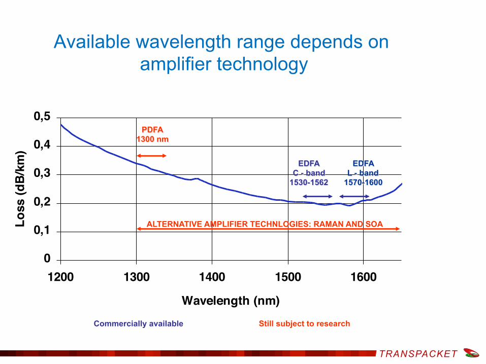
Available wavelength range depends on amplifier technology
0
0,1
0,2
0,3
0,4
0,5
1200 1300 1400 1500 1600
Wavelength (nm)
Loss
(dB/
km)
EDFA C - band
1530-1562
EDFA L - band
1570-1600
ALTERNATIVE AMPLIFIER TECHNLOGIES: RAMAN AND SOA
PDFA 1300 nm
Commercially available Still subject to research

TRANSPACKET
Erbium Doped Fiber Amplifier (EDFA)
• Widely deployed in optical networks

TRANSPACKET
Dispersion Compensating Fibre (DCF)
• Negative dispersion compared to transmission fibre
• Much higher dispersion/km => Shorter fibre than transmission fibre required for achieving zero dispersion

TRANSPACKET
Long distance fibre-optical transmission
Transmitter (Laser+
modulator)
Receiver (fotodiode +
amplifier) Long Fibre
Compensation of amplitude and dispersion
EDFA DCF

TRANSPACKET
Fibre optical transmission system
Receiver Optical fibre Single modus
Electric input data
Laser & modulator
Amplifier or
regenerator Optical fibre Single modus
Electric output data
Wavelength Division Multiplexing (WDM) transmission system: Add lasers & modulators + receivers
Time Division Multiplexing = TDM

TRANSPACKET
100 Gb/s per channel fibre optical transmission system
Receiver Optical fibre Single modus
Electric input data
Laser & modulator
Amplifier or
regenerator Optical fibre Single modus
Electric output data
Polarisation multiplexing: Doubles capacity
PBS
PBS Combine!

TRANSPACKET
ISP
Mobile
Optical networks
Metro Routers/optical switches
Core Optical switches/routers
Access Ethernet switches

TRANSPACKET
Mobile
Wavelength services
Metro Routers/optical switches
Core Optical switches/routers
Access Ethernet switches
ISP
Wavelength !service!
Wavelength !service!

TRANSPACKET
Network element functionality (1)
• 70 % of traffic is through-passing in typical node => Should be able to avoid processing of this traffic.
• Simple optical network element – Static Optical Add-Drop Multiplexer
(here: ring network): ● Fixed wavelengths
dropped and added at each node.
● Not reconfigurable (inaccessible to control system).

TRANSPACKET
Network element functionality (2)
• Traffic bypassing intermediate IP routers => Less load on routers (can be smaller and cheaper)
• In meshed networks: Used to directly connect node pairs with high traffic between them.

TRANSPACKET
Reconfigurable (R-)OADM • A flexible add-drop function • Use cross-connect for some wavelength/
wavebands
Not single wavelength!
TRANSPACKET
Networking requirements
Wanted: High capacity optical layer network with the following requirements:
• Support high utilization of resources • Support high granularity • Support quality needed for strict real-time
services • Support variable length packets

TRANSPACKET
Optical Packet switching • More complicated in the optical domain:
– Higher speeds needed in switches – Not (currently) available technology for optical
processing of headers etc. – The payload information is switched optically – Optical buffering is difficult!
OXC Controller
Node Controller (e.g., MPLS)
Delay <= header length+ processing time
Header processor
To OXC-control
Skiller header og nyttelast
DMUX’er WDM signal
Optiske buffere
Optisk krysskopler
MUX’er signaler til WDM signal
Optical crossconnect (with or without wavelength conversion)
Optical buffers (to handle contention on output)
Mux of signals to a WDM signal
Separates header and payload
Demux of WDM signals
TRANSPACKET
• Wavelength and OTN services have a high production cost – Occupies a physical wavelength or TDM channel
resource in the network – Wavelengths/TDM channels are limited resources – Wavelengths/TDM channels occupies resources end-to-
end – no intermediate additional aggregation possible • Ethernet or VPN service preferred as compromise
– Lower production cost (oversubscription/statistical multiplexing)
– Does not offer transparency and performance (especially latency) as for wavelengths and OTN channels
35
Carrier pain
TRANSPACKET
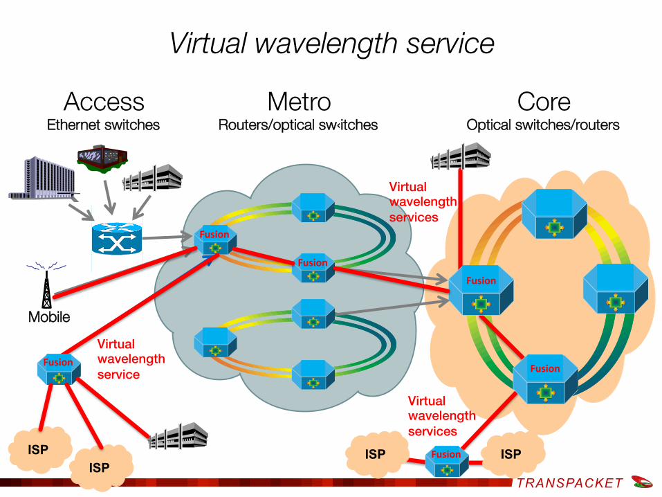
Mobile
Virtual wavelength service
Metro Routers/optical sw‹itches
Core Optical switches/routers
Access Ethernet switches
ISP
Fusion
ISP
Virtual!wavelength !services!
Virtual!wavelength !service!
Fusion
Fusion
Fusion
Fusion
ISP Fusion ISP
Virtual!wavelength !services!

TRANSPACKET
D B
GST lightpath from A→D
Underutilized circuit (wavelength): FUSION fills it!
Incoming GST packets destined for node D
Time between packets is unused L
– Pure WDM system (circuit) gives low channel utilization
– For 270 Mb/s video on a 1 Gbps, 70 % of capacity is wasted
OpMiGua switch will insert lower quality (Internet) traffic in voids
Transit traffic passes through on optical layer with minimum or no processing
B
C
C
Packet Switch
D
Input Queue Output Queue A C
D
C D
D
D
C

TRANSPACKET
• Fusion Packet optical networking Add-Drop Muxponder ‒ 2 x 10 Gigabit Ethernet line-interfaces ‒ 10 x 1 Gigabit Ethernet client-interfaces
• 10 Gigabit Ethernet wavelength or circuit • Sub-wavelength switching: Gigabit Ethernet Packet or
circuit paths • Optional passive or active optical module
– CWDM, DWDM, OADM
TransPacket H1 – the first fusion product
GbE 10GbE Optional optical module

TRANSPACKET 39
• Typical scenario – Invest at 50% fill rate – 10 - 30% utilization
• TransPacket H1 – Intelligent Traffic Injection – Exploit capacity without
affecting existing traffic – Monetize on idle capacity – Postpone capacity upgrade 0
10 Gb/s
Utilized capacity
Available capacity
Vacant fiber-bandwidth can be utilized

TRANSPACKET
Example Trondheim-Oslo field trial Utilize network capacity
• 10G Virtual wavelength • 600 km transmission of 10 Gb/s Ethernet • More capacity: Intelligent Traffic Injection (ITI)
UNINETT Router Trondheim
TransPacket H1 TransPacket H1
Transport/Metro network
UNINETT Router Oslo
Nokia Siemens WDM system
Extra capacity Extra capacity
Fibre 600 Km
WDM WDM
10 Gb/s 10 Gb/s

TRANSPACKET
Results Trondheim-Oslo – stress test • Green: Traffic during World championship cross-
country skiing, Trondheim-Oslo both directions • Blue: Added SM traffic
– 1- 6 Gb/s of added traffic

TRANSPACKET
Controlling the optical network
• Network management system (NMS) working across vendors and network layers is required
• Setup and tear down of wavelengths according to capacity needs
OADM OADM
OADM
OADM OADM
NMS

TRANSPACKET
Controlling across network layers
• Applications triggers resource usage on servers • Server communication triggers network capacity
needs • IP- routers requires capacity from the optical network • Optical network must deliver resources on demand
from upper layers
TRANSPACKET
Controlling across network layers
• Applications triggers resource usage on servers • Server communication triggers network capacity
needs • IP- routers requires capacity from the optical network • Optical network must deliver resources on demand
from upper layers
Software defined networks (SDN)?

TRANSPACKET
SDN: The new hype and research area
Software Defined Networking Can it be combined with optical
networking?

TRANSPACKET
SDN goals (carrier view)
• Centralized control of network resources • Control across network layers • Control independent of equipment vendor

TRANSPACKET 47
SDN Logical Architecture
Centralized intelligence and network state knowledge to configure the devices
Applications see the network as a single, logical switch controlled via abstracted API
Enterprises and carriers gain vendor-independent control over the entire network from a single logical point, which greatly simplifies the network design and operation.
Simplified network devices do not need to process all routing/switching protocols
Example application: Load balancing

TRANSPACKET
Specialized Packet Forwarding Hardware
Feature Feature
Specialized Packet Forwarding Hardware
Specialized Packet Forwarding Hardware
Specialized Packet Forwarding Hardware
Specialized Packet Forwarding Hardware
Operating System
Operating System
Operating System
Operating System
Operating System
Network Operating System
Feature Feature
Feature Feature
Feature Feature
Feature Feature
Feature Feature
The OpenFlow Network Innovation
Source: S.Seetharaman, OpenFlow/SDN tutorial, OFC/NFOEC 2012

TRANSPACKET
49
Specialized Packet Forwarding Hardware
Specialized Packet Forwarding Hardware
Specialized Packet Forwarding Hardware
Specialized Packet Forwarding Hardware
Specialized Packet Forwarding Hardware
Network Operating System
Feature Feature
The OpenFlow Network Innovation
Source: S.Seetharaman, OpenFlow/SDN tutorial, OFC/NFOEC 2012
OpenFlow
OpenFlow
OpenFlow
OpenFlow
OpenFlow
1. Open interface to hardware
3. Well-defined open API 2. At least one good operating system Extensible, possibly open-source

TRANSPACKET
SDN Multidomain control: Much more than openflow
introduced two QoS classes (Fig.1D) in the COP call definition (Fig.1C, trafficParams). Each QoS class defines a certain packet loss rate (PLR) for OPS domains, and a certain OSNR for OCS domains, for a given bandwidth request. The SDN orchestrator will translate the high level QoS classes into the necessary parameters in the calls sent to the different SDN controllers. Fig.2A shows the message exchange between the different involved computing and network elements in order to jointly provide interconnected VMs with QoS. The provisioning of the VMs is requested to each responsible cloud controller, while the VM interconnection is requested to the SDN orchestrator with an E2E call (ID: 1) including a QoS class. The SDN orchestrator computes the E2E path and requests the necessary calls (IDs: 10, 11, 12, 13) to the different SDN Controllers. Fig.2B shows the wireshark captures at the integrated cloud and network orchestrator and at the SDN orchestrator. Per-domain / E2E service recovery with QoS Fig.3A shows three conducted experiments for QoS recovery: in an OPS domain (scenario A), in an OCS domain (scenarios B, C) and finally E2E QoS recovery (scenario D). Per-domain QoS recovery through adaptive route control in the OPS network. Fig. 3B shows the experimental setup of the OPS domain in NICT premises in Japan. The OPS nodes used are optical packet and circuit integrated nodes4, including one SOA-based 4 × 4 optical packet switch (4 × 4 OPS). In the control plane, an OF-based SDN controller is used to control the OPS nodes. Four OPS nodes with optical packet counters are used, including OF agents and OPS transmitters and receivers. The OF agent periodically reads and provides to SDN controller
the optical packet count information that is measured. In this use case, two E2E transport connections are setup involving the OPS domain, flow1 with a packet occupancy rate of 10% and flow2 with a packet occupancy rate of 2%. In this case, the PLR for flow1 measured by a tester is around 4%. When we increase the packet occupancy rate of flow2 from 2% to 6%, the optical packet counter of OPS node 4 reaches the pre-defined threshold indicating packet congestion. Fig. 3C shows the measured packet counts of Node 4. With the increase of the packet occupancy rate, packet count at OPS node 4 is finally smaller than 17000, corresponding to the pre-defined packet count threshold. The OF agent attached to OPS node 4 detects packet congestion and sends an alarm message to the SDN controller. The SDN controller receives the alarm and then issues the route adaption for the switching table of node 2, aiming at improving the PLR. After the route control, the obtained PLR for flow1 measured by the traffic tester is reduced from around 4% to 0.1%. Route adaptation is announced to SDN orchestrator by means of COP notification mechanism (using websocket). QoS recovery in an OCS domain. For same BER performance, the required OSNR value will relax when a signal with a lower order modulation format is used5. Fig.3E shows the tested OSNR vs. BER curve for our 28Gbaud PM-QPSK and PM-16QAM transmitters. QPSK requires an OSNR value less than that of 16QAM about 9dB at HD-FEC threshold (3.8E-3). Moreover, OSNR monitoring of a circuit flow can detect the OSNR degradation for optical links. The receiver-side error-vector-magnitude (EVM) based OSNR monitor provides in-band OSNR monitoring without deploying new hardware6. With monitoring information, the COP can
Fig. 1: A) Proposed LIGHTNESS-STRAUSS scenario; B) Abstracted network/cloud scenario; C) Call example, D) QoS classes
A)
B)
C)D)
Fig. 2: A) VM connectivity provisioning workflow; B) Wireshark capture.
A) B)
Ecoc 2015 - ID: 1061
R. Vilalta et.al. ECOC 2015: First experimental demonstration of distributed cloud and heterogeneous network orchestration with a common Transport API for E2E service provisioning and recovery with QoS
Control Orchestration Protocol (COP) for communication with controllers for each domain and vendor.

TRANSPACKET
Summary • Optical fibres are the ultimate transmission
medium – Long range, Terabit capacity now, petabit in
research • Optical networking enables switching of
high bitrate wavelengths • A common control and management of the
network layers is required – Preferably standardized – working across
vendors • Is SDN the solution?

TRANSPACKET