infant child restraint system
TRANSCRIPT

i"
"
" "
" "
"
"
"
"
"
"
"
"
"
"
"
"
"
"
"
"
"
"
"
"
"
"
"
"
"
" "
DESIGN AND PRELIMINARY FINITE ELEMENT ANALYSIS OF STRUCTURAL FRAME OF A DOUBLE BASE FOR AN INFANT CHILD RESTRAINT SYSTEM "
Bachelor Degree Project in Mechanical Engineering C-Level 22.5 ECTS Spring term 2015 Nikita Popov Popov Supervisor: Moyra McDill Examiner: Karl Mauritsson

"
"
"
ii"
Abstract!Child" restraint" systems" (CRS)" are" used" for" protection" of" the" child" in" case" of" car" accident." These"
systems"have"been"found"to"have"a"difficult"installation"process"that"in"many"cases"can"cause"greater"
loads"on" the"child"and"as"a" consequence"can" lead" to"an" increased" risk"of" injury"and"a" reduction" in"
safety."The"problems"are"even"more"significant"in"cases"of"families"with"two"or"more"children"and"in"
small"cars"with"lack"of"available"space."Misuse"and"its"causes"are"identified"from"literature"as"well"as"
from" surveys" and"market" research." The" design" guidelines" are" gathered" from" existing" CRS" designs."
Currently" available" automotive" and" CRS" fastening" systems" are" studied." A" specific" methodological"
approach"is"used"for"project"development."A"new"concept"for"a"child"restraint"system"is"introduced."
The"main" aims" are" the"design"proposal" of" a" double" ISOFIX"base" for" two" children," reduction" in" the"
misuse" of" the" CRS," improving" the" user" experience" and" achieving" technological," societal" and"
environmental" contributions." The" second" aspect" is" to" verify" the" structure" of" the" double" base" by"
means" of" preliminary" finiteIelement" analysis" using" the" case" of" a" frontal" collision" in" accordance" to"
current" approval" testing" procedures." Al" 2024" is" chosen" for" design" by" the" material" selection"
performed"in"order"to"optimize"the"structure"in"relation"to"strength"and"weight."The"finiteIelement"
preliminary" static" analysis" is" performed" employing" shell" elements." The" results" are" analysed" with"
respect"to"the"mesh"convergence." In"addition"a" linearized"buckling"check" is"carried"out."Finally," the"
achieved" results"are"discussed" in"comparison"with" initial"assumptions"and"goals"and" future"work" is"
suggested.!
Key"words:"child"restraint"system,"ISOFIX,"finiteIelement"analysis,"product"development." "

"
"
"
iii"
Certification!This"thesis"has"been"submitted"by"Nikita"Popov"Popov"to"the"University"of"Skövde"as"a"requirement"
for" the"degree"of"Bachelor"of" Science"in"Mechanical" Engineering." The"undersigned" certifies" that" all"
the"material"in"this"thesis"that"is"not"my"own"work"has"been"properly"acknowledged"using"accepted"
referencing"practices" and," further," that" the" thesis" includes"no"material" for"which" I" have"previously"
received"academic"credit."
""
Nikita"Popov"Popov"" " " " ""
Skövde"2015I05I19"
Institutionen"för"Ingenjörsvetenskap/"Department"of"Engineering"Science"
" "

"
"
"
iv"
Acknowledgements!In"the"first"place"I"would"like"to"express"my"deep"gratitude"to"Moyra"McDill,"my"project"supervisor"for"
giving"me"important"guidelines,"inspiration"and"support"through"project"development."I"also"want"to"
express" my" acknowledgements" to" the" Product" Development" department" team" and" thank" the"
University"of"Skövde"for"providing"necessary"resources"to"carry"out"parts"of"present"work." !
v"
"
" "
Table!of!Contents!Abstract!.............................................................................................................................!ii"
Certification!.......................................................................................................................!iii"
Acknowledgements!...........................................................................................................!iv"
List!of!Figures!.....................................................................................................................!vi"
1" Introduction!.................................................................................................................!1"1.1" Background!........................................................................................................................!1"1.2" Product!Development!........................................................................................................!4"1.3" Problem!Statement!............................................................................................................!4"1.4" Overview!............................................................................................................................!4"
2" Approach!.....................................................................................................................!5"2.1" General!..............................................................................................................................!5"2.2" Specific!...............................................................................................................................!5"
3" Design!envelope!..........................................................................................................!6"3.1" Dimensions!of!automotive!interiors!...................................................................................!6"3.2" Materials!............................................................................................................................!8"3.3" Specifications!.....................................................................................................................!8"3.4" Preliminary!concept!design!................................................................................................!9"
4" FiniteMelement!analysis!...............................................................................................!10"4.1" Simplification!hypotheses!................................................................................................!11"4.2" Boundary!conditions!........................................................................................................!11"4.3" Loads!...............................................................................................................................!12"
4.3.1" Calculation"of"impact"force.".............................................................................................."13"
4.4" Material!data!...................................................................................................................!13"4.5" Results!of!analyses!...........................................................................................................!17"
4.5.1" Check"for"buckling"............................................................................................................."21"
5" Discussion!...................................................................................................................!22"
6" Conclusions!.................................................................................................................!23"
7" Future!work!................................................................................................................!24"
References!........................................................................................................................!25"
Appendix!1.!Work!breakdown!...........................................................................................!27"
Appendix!2.!Time!plan.!.....................................................................................................!28"
Appendix!3.!Drawings!and!final!product!presentation!.......................................................!29"
Appendix!4.!Results!of!simulations.!...................................................................................!31"" "

"
"
"
vi"
List%of%Figures!FIGURE"1."CHILD"RESTRAINT"SEAT"...................................................................................................................................."1"
FIGURE"2."USE"OF"THE"SEATBELT"TO"FIX"THE"CRS"................................................................................................................"2"
FIGURE"3."ISOFIX"SYSTEM"............................................................................................................................................."3"
FIGURE"4."HOW"TO"INSTALL"ISOFIX"BASE"........................................................................................................................."3"
FIGURE"5."TYPICAL"AUTOMOTIVE"DIMENSIONS"..................................................................................................................."7"
FIGURE"6."SKETCH"OF"PRELIMINARY"DESIGN."...................................................................................................................."10"
FIGURE"7."BOUNDARY"CONDITIONS"DETAIL."ISOFIX"ANCHORS."..........................................................................................."11"
FIGURE"8."BOUNDARY"CONDITION"DETAIL."SUPPORT"LEG."..................................................................................................."12"
FIGURE"9."ACCELERATION"PULSE"CORRIDOR."...................................................................................................................."12"
FIGURE"10."CES"SELECTOR,"LEVEL"1."............................................................................................................................."14"
FIGURE"11."CES"SELECTOR,"PERFORMANCE"INDEX"SLOPE,"LEVEL"3."......................................................................................"15"
FIGURE"12."CES"SELECTOR,"LEVEL"3."ALUMINIUM"ALLOYS."................................................................................................."15"
FIGURE"13."CES"SELECTOR,"LEVEL"3."ALUMINIUM"ALLOYS,"COSTS."......................................................................................."16"
FIGURE"14."AL"2024"T36"TRUE"STRESSITRUE"STRAIN"CURVE."............................................................................................."16"
FIGURE"15."STRESS"DISTRIBUTION"ACCORDING"TO"VON"MISES."..........................................................................................."17"
FIGURE"16."STRESS"DISTRIBUTION"ACCORDING"TO"MAX."PRINCIPLE"STRESS."............................................................................"18"
FIGURE"17."STRESS"DISTRIBUTION"WITHOUT"SHARP"EDGES,"VON"MISES."..............................................................................."18"
FIGURE"18."MESH"OF"THE"PART."..................................................................................................................................."19"
FIGURE"19."MESH"OF"THE"PART,"CLOSE"DETAIL."................................................................................................................"19"
FIGURE"20."8INODE"SHELL"ELEMENT"(S8/S8R)."..............................................................................................................."19"
FIGURE"21."MESH"SENSITIVITY"STUDY,"S4R"ELEMENTS"......................................................................................................"20"
FIGURE"22."MESH"SENSITIVITY"STUDY,"S8R"ELEMENTS"......................................................................................................"20"
FIGURE"23."BOUNDARY"CONDITIONS"FOR"BUCKLING"CHECK."..............................................................................................."21"
FIGURE"24"LINEARIZED"BUCKLING"CHECK."........................................................................................................................"21"
FIGURE"25."WORK"BREADOWN"DIAGRAM."......................................................................................................................"27"
FIGURE"26."ORIGINAL"GANTT"CHART"AND"TIME"PLAN."......................................................................................................."28"
FIGURE"27."UPDATED"GANTT"CHART"AND"TIME"PLAN."......................................................................................................."28"
FIGURE"28."REPRESENTATION"OF"THE"FINAL"PRODUCT."BACK"VIEW."....................................................................................."29"
FIGURE"29."REPRESENTATION"OF"THE"FINAL"PRODUCT."......................................................................................................"29"
FIGURE"30."INICAR"REPRESENTATION"OF"THE"FINAL"PRODUCT."............................................................................................"29"
FIGURE"31."TECHNICAL"DRAWING"OF"THE"STRUCTURE"OF"THE"DOUBLE"BASE.".........................................................................."30"
FIGURE"32."STRESS"DISTRIBUTION,"VON"MISES,"S4"ELEMENTS..".........................................................................................."31"
FIGURE"33."STRESS"DISTRIBUTION,"MAX."PRINCIPLES,"S4"ELEMENTS."..................................................................................."32"
FIGURE"34."MAX."DISPLACEMENT,"S4"ELEMENTS."............................................................................................................."32"
FIGURE"35."STRESS"DISTRIBUTION,"VON"MISES,"S8"ELEMENTS."..........................................................................................."33"
FIGURE"36."MAX."DISPLACEMENT,"S8"ELEMENTS."............................................................................................................."33"
FIGURE"37."STRESS"DISTRIBUTION,"VON"MISES,"S4R."......................................................................................................."34"
FIGURE"38."STRESS"DISTRIBUTION,"MAX."PRINCIPLES,"S4R."..............................................................................................."34"
FIGURE"39."MAX."DISPLACEMENT,"S4R."........................................................................................................................."35"
FIGURE"40."STRESS"DISTRIBUTION,"VON"MISES,"S8R."......................................................................................................."35"
FIGURE"41."MAX."DISPLACEMENT,"S8R."........................................................................................................................."36"
FIGURE"42."STRESS"DISTRIBUTION,"VON"MISES,"S8R,"WITHOUT"STRESS"CONCENTRATIONS."......................................................"36"
FIGURE"43."STRESS"DISTRIBUTION,"MAX."PRINCIPLES,"S8R,"WITHOUT"STRESS"CONCENTRATIONS.".............................................."37"
FIGURE"44."MAX."DISPLACEMENT,"S8R"ELEMENTS,"WITHOUT"STRESS"CONCENTRATIONS."........................................................."37"
FIGURE"45."BUCKLING"MODE"1...".................................................................................................................................."39"
FIGURE"46."BUCKLING"MODE"2...".................................................................................................................................."39"
FIGURE"47."BUCKLING"MODE"3...".................................................................................................................................."40"
FIGURE"48."BUCKLING"MODE"4."...................................................................................................................................."40"

1"
"
" "
1 Introduction!Child" restraint" systems" (CRS)" such" as" infant" car" seats" are" designed" to" protect" the" occupant" in" the"
event" of" an" accident." However," the" safety" of" these" seats" is" subject" to" the" correct" use" of" the"
attachment" systems" by" the" parent" or" caregiver" (Anund" et" al.," 2003)." As" is" evidenced" by" the" large"
number" of" onIline" videos;" e.g.," (About.com," 2010)," installation" of" a" CRS" can" be"more" complicated"
than" expected." This" unforeseen" difficulty" could" result" in" misuse" of" a" CRS" and" a" corresponding"
reduction" in"protection" in" case"of" accident." That" complexity" is" increased"when" two,"or"more," child"
safety" seats"or"different"models"and"sizes"are"used."Figure"1" shows"a" typical" child" restraint" system"
with"a"base"that"is"fixed"to"the"seat"and"a"basket"into"which"the"child"is"belted."
!
"
"
"
!
"
!
"
"
"
"
"
1.1 Background!Many" finite" element" (FE)" analyses" of" CRSs" exist" in" the" literature;" e.g.," (Baranowski" et" al.," 2014;"
Kapoor"et"al.,"2011),"but"the"majority"of"these"studies"are"dedicated"to"the"dynamic"analysis"of"the"
seat’s"mechanical"behaviour"and"the"effect"on"the"child"in"the"event"of"an"accident."However"some"
research" shows" that" in"many" cases"CRSs" have"been"misused." Typical" errors" include" the"use"of" the"
improper" seat" for" the" height" or"weight" of" the" child," the" child’s"medical" condition" and" installation"
issues."In"Sweden,"the"percentage"of"misuse"is"nearly"40%"(Pitcher"et"al.,"2011;"Anund"et"al.,"2003)."
Misuse"not"only"reduces"the"protection"but"also"increases"the"risk"of"injury."Often"the"installation"is"
physically" more" difficult" than" expected" and" together" with" a" lack" of" available" space" to" properly"
manipulate"the"CRS"inside"the"car,"leads"to"improper"installation."In"some"cases"the"design"of"the"CRS"
makes" difficult" to" avoid" errors" during" the" placement" of" seat." In" case" of" transporting" two" children,"
such"as"twins"or"an"infant"and"a"toddler,"the"user"must"install"two"separate"CRSs."In"small"cars,"this"
severely" limits" the"available"space" (McDill,"2015)."Further," there"does"not"appear" to"be"CRS"on"the"
market"that"can"be"used"for"twins."
Figure!1.!Child!restraint!seat!(BeSafe,!2015).

"
"
"
2"
Currently"there"are"two"ways"of"fastening"the"CRS:"using"the"existing"car"seatbelt"(Figure"2)"or"using"
the"ISOFIX"system"(Langwieder"et"al.,"2003)."Both"systems"have"advantages"and"disadvantages."The"
automotive"seatbelt"is"designed"to"provide"protection"to"the"adult"passenger"and"although"it"offers"a"
reasonable"safe"restraint"of"the"CRS," it" is"subject"to"correct" installation"and"a"tightening"check."The"
use"of"seatbelt"to"restrain"the"CRS"implies"that"the"user"has"to"ensure"that"the"belt"is"correctly"routed"
and"tightened."This" is"often"difficult"to"achieve"due"to"design"of"the"CRS"or" limitations" in"the"user’s"
strength." If" the"belt" is" too" tight," it" could" lead," in" some"seat"designs," to" releasing" the"belt" from" the"
buckle"leaving"the"CRS"unfixed."In"case"of"belt"slack,"the"loads"on"the"child"during"collision"are"30"to"
40%"higher"than"with"an"optimally"tight"belt" (Langwieder"et"al.,"2003)." If" the"CRS" is"not"completely"
restricted,"the"belt"slack"allows"the"CRS"to"continue"moving"even"while"the"car"is"slowing"during"the"
impact."According"to"Langwieder"et"al."(2003),"this"causes"a"greater"deceleration"of"CRS"and"increases"
the"head"excursion"of"the"child.""
"
"
"
"
"
"
"
"
"
"
"
"
The"ISOFIX"system"was"introduced"by"International"Organization"for"Standardization"(ISO)"in"order"to"
reduce"installation"mistakes"and"simplify"the"fastening"process."The"system"is"based"on"two"anchor"
points"located"in"the"seat"cushion"as"it"shown"in"Figure"3."The"complete"CRS"or"the"CRS"base"has"to"
be" fastened" to" existing" inIcars" ISOFIX" brackets" (as" Figure" 4" shows)" that" avoid" forward" and" side"
movements"of"the"CRS."
"
"
"
"
Figure!2.!Use!of!the!seatbelt!to!fix!the!CRS!(CarSeatBlog,!2012).!

"
"
"
3"
"
"
"
"
"
"
"
"
"
"
"
"
"
"
"
"
"
"
"
"
According" to" Langwieder" et" al." (2003)," misuse" rates" of" ISOFIX" systems" have" been" shown" to" be"
noticeably" lower" than" those" found" using" conventional" restraint" systems." The" ISOFIX" system" also"
provides"a"similar"level"of"protection"to"the"child"(Wang"et"al.,"2007;"Kapoor"et"al.,"2005)."Taking"into"
account" that" the" protection" remains" high" and" that" installation" errors" are" decreased," it" seems" that"
ISOFIX" could" be" a" definitive" solution." However" in" majority" of" cases" ISOFIX" has" to" be" used" with"
additional" attachment"measures" such" as" a" top" tether" for" a" frontIfacing" CRS" or" a" support" leg" for" a"
rearIfacing"CRS."The"employment"of"these"attachments"is"necessary"to"limit"the"rotation"of"the"CRS"
about"the"ISOFIX"anchors"caused"by"a"large"spacing"between"them"and"CRS"centre"of"mass."However"
the"need"for"the"extra"attachment"contradicts"soIcalled"ease"of"use"of"ISOFIX.""
Figure!3.!ISOFIX!system!(Britax,!2015).!
Figure!4.!How!to!install!ISOFIX!base!(MaxiMCosi,!2015).!

"
"
"
4"
As"performed"market"research"shows"that"the"percentage"of"twin"babies"has"been"growing"in"recent"
years."According"to"Testa"(2011),"the"distribution"of"European"families"is"mostly"focused"to"have"two"
children." When" using" two" CRS" independently" it" is" difficult" to" install" them" sideIbyIside" inside" the"
vehicle." This" leads" to" install" them" in" separated" seat" cushions" leaving" the" centre" seat" (most" often)"
without"enough"space"for"another"occupant."One"of"the"main"ideas"of"the"double"base"is"to"solve"this"
problem"and"provide"more"free"space"in"the"rear"seats."
1.2 Product!Development!As" this" project" is" elaborated" together" with" students" from" Product" Development" Engineering," the"
design"of"the"double"base"is"performed"from"both"perspectives:"mechanical"and"design"engineering."
Design"engineering"part"focuses" in"aspects"such"as"usability,"ergonomic"study,"market"research"and"
some"material"considerations"inter"alia."A"detailed"work"breakdown"can"be"found"in"Appendix"1."
1.3 Problem!Statement!The"main" goal" of" this" project" is" to"design"a"new" ISOFIX" frame" for" a"base" for" an" infant" child" safety"
system" that" allows" two" infant" carrying" baskets" of" the" same"or" different" size" to" be" safely" fastened"
according"to"the"current"regulations"(Economic"Commission"for"Europe"of"the"United"Nations,"2004)."
The"secondary"goal"is"to"improve"the"user"experience,"reducing"physical"requirements"from"the"user"
as"well"as"improve"the"overall"safety"by"avoiding"installation"mistakes."From"a"market"research"study"
performed"by"Product"Development"department," it"can"be"observed"that" there" is"strong" indication"
that" the" percentage" of" twin" newIborns" is" relatively" high" and" at" least" 30%" of" actual" families" have"
children" with" an" age" difference" of" 1" to" 3" years." These" facts" suggest" the" need" for" a" new" solution"
regarding"the"children"transportation"inside"the"car."The"present"work"attempt"to"solve"issues"related"
with" technology," society" and" environmental" aspects" regarding" the" use" of" the" CRS." Numerical"
analyses,"presented" in" the" current" literature," e.g.," (Altenhof"and"Turchi," 2004;"Kapoor"et" al.," 2011)"
provide"a"reference"for"the"development"of"new"structure"for"the"double"base"and"safe"fastening"of"
two"infant"safety"seats."The"third"goal"is"to"model"the"base"and"use"finite"element"method"to"analyse"
the"proposed"structural"frame"of"the"base.""
"
The"main"constraints"of"the"present"work"are"determined"by"the"aspects"of"existing"CRS"designs"such"
as" currently"employed"manufacturing"processes,"usability," legal" aspects"and"compatibility"between"
cars"and"the"CRS"baskets."
"
In"summary"the"principal"objectives"are"to:"
• propose"a"new"design,"including"material"selection"if"required,"of"the"double"base"and"
its"fixtures,"that"satisfies"all"specified"requirements;"
• perform"a"preliminary"FEIanalysis"to"verify"the"structural"frame"of"the"proposed"design"
of"the"double"base.""
"
1.4 Overview!!To" accomplish" the" objectives" of" the" project" the" choice" of" conceptual" design" is" made" based" on"
specifications"matrix" that" can" be" found" in" section" 3.3." Corresponding" sketches" are" elaborated" and"
presented" in"section"3.4."ThreeIdimensional" (3D)"model"development"and"analysis"of" the"model"by"

"
"
"
5"
the" finite" element" method" and" material" selection" in" accordance" with" current" manufacturing"
standards"are"presented"in"section"4."The"mechanical"behaviour"is"verified"with"a"loading"behaviour"
test" related" to" a" case" of" car" frontal" collision." The" results" are" presented" according" to" the"material"
failure" criteria."Discussion" in" relation" to"achieved" results"and" initial" goals" is"presented" in" section"5."
Conclusions"and"future"work"suggestions"can"be"found"in"section"6"and"7"respectively."""
2 Approach!
2.1 General!First" of" all," the" literature" search" and" study"was" carried" out" in" order" to" find" new" and" enhance" the"
existing"information"about"CRS"in"general"as"well"as"numerical"simulations"in"the"field"of"CRS"safety."
Later,"the"design"of"several"conventional"rearIfacing"and"frontIfacing"infant"CRS"was"studied"in"detail."
This"analysis"provided"the"necessary"knowledge"for"understanding"how"the"CRS"are"made,"how"they"
can" be" fastened" and" which" behaviour" they" tend" to" show" under" usual" load" cases." Also" the" issues"
related"to"the"normal"use"of"CRS"were"designated."Typical"car"restraint"features"were"identified.""
Once" the"main" features"of"CRS"and"vehicles" in"general"were"clear," the"next" step"was" to"propose"a"
preliminary" geometry" design" for" the" double" base" structural" frame" which" has" to" fulfil" all" key"
requirements" identified" in" the" literature"study"and"also" in"order" to"achieve" the" technology," society"
and" environmental" contributions." This" step" was" done" in" cooperation" with" product" development"
department" group" with" the" purpose" of" applying" a" proper" design" methodology," to" avoid" possible"
subsequent"and"multiples"reIdesigns"and"also"to"achieve"the"goals"facing"the"product"design"from"the"
global" perspective." Several" methods" of" idea" generation" and" concept" evaluation" were" performed"
identifying"problems" that"appeared" in" the"design"process."This"gave"as"a" result" the" final"geometric"
model.""
Once"the"geometry"was"verified,"the"next"step"was"the"creation"of"a"threeIdimensional"(3D)"model"in"
order" to"execute" subsequent" finiteIelement" (FE)" analyses"of" the"base" frame." For" this"purpose," key"
literature" mentioned" before" was" reviewed" in" order" to" develop" suitable" load" case" and" boundary"
conditions." The" materials" that" were" proposed" for" base" and" frame"manufacture" were" determined"
from" the" analysis" of" existing" CRS," however"material" selection" was" performed" according" to" design"
specifications." After" running" the" simulations," the" results" were" examined" to" prove" its" validity" and"
translated"to"design"constraints"or"requirements"with"the"purpose"of"verify"the"model"or"initiate"reI
design"if"necessary."
2.2 Specific!The"literature"study"was"accomplished"with"academic"support"provided"by"supervisor,"examiners"and"
university"personnel"and"also"on"its"own."Through"the"design"process"several"methods"were"applied"
according"to"previously"elaborated"methodology."Some"of"these"methods"were"idea"generation"and"
specification"clarifying"methods"and"techniques"such"as"brainstorming,"brainwriting"pool,"dark"horse"
prototype,"SWOT"(strengths,"weaknesses,"opportunities,"threats)"and"objective"tree"method"(Cross,"
2008)."The"concept"generation"was"made"by"drawing"several"sketches"and"employing"3D"visualisation"
by"means"of"computer"assisted"design" (CAD)" software" (PTC/Creo"Parametrics"2.0)."With" respect" to"
concept"evaluation"and"according"to"Cross"(2008),"PMI"(Plus/Minus/Interesting)"and"Pugh’s"selection"
matrix"methods"were" used." The" problems" and" inconsistent" solutions"were" discarded" and" the" final"

"
"
"
6"
geometry"was"achieved"by"reviewing"and"improving"previous"sketches."The"design"of"the"geometry"
of"the"base"was"developed"according"to"the"requirements"and"specifications"that"were"found"in"the"
literature" review" and" identifying" problems" that" appeared" during" the" double" base" concept"
development.""
The" final" 3DImodel"was"elaborated"using"PTC/Creo"Parametric"2.0." The"geometry"was"exported" to"
ABAQUS" 6.13" for" FEIanalysis" in" relation" to" material" solid" mechanics." The" simulations" were" made"
performing" the" simplification" considerations," the" element" type" choice," setting" the" boundary"
conditions"and"selecting"the"most"suitable"type"of"analysis.""
Guidelines" for" load" case" and" boundaries" determination" were" extracted" from" the" literature" study."
Material"selection"was"done"in"accordance"to"design"specification"using"CES"EduPack"2014"software,"
calculating" performance" indices" to" optimize" the" strength" and" weight" of" employed" materials" and"
taking" into"account" important" technological"and"environmental"aspects."A"detailed"presentation"of"
the"FEIanalyses"proceedings"can"be"found"in"section"4."
3 Design'envelope!
3.1 Dimensions!of!automotive!interiors!Since"not"all"the"CRS"are"compatible"with"all"the"cars"(AA,"2012)"the"design"of"the"double"base"cannot"
be"universal."According"to"statistics"provided"by"Focus2Move.com"(2014)," in"Sweden"the"mostIsold"
cars" in" 2014"were" Volvo" V70," Volkswagen"Golf" and" Volvo" S/V60." In" Europe," the"mostIsold" cars" of"
2014"were" Volkswagen"Golf," Volkswagen" Polo" and" Renault" Clio." Clearly" the" small," CIsegment" cars"
(except"Volvo"V70)"are"currently"the"most"popular."For"this"reason"the"design"of"the"double"base"is"
focused"on" this" type"of" car." It"was"necessary" to"determine" the" relevant"dimensions"as" certain"CRS"
fixtures"that"are"available"in"these"cars.""
Before"presenting"the"car"seats"and"available"space,"it"was"necessary"to"examine"where"the"child"or"
the"children"must"be"seated"when"travelling"by"car"or,"in"other"words,"where"to"place"the"CRS."Lund"
(2005)" shows" that" the" safest" positions" in" the" car" are" the" rear" seats," independently" of" location"
because" the" risk"of" injuries" in"case"of"accident" is" the" same" in" right," centre"or" left" seat" cushions." In"
case"of"a"twin"base"the"front"seat"placing"position"cannot"be"used"for"the"CRS.""
Automotive"dimensions"of" interest"with"respect"to"the"double"base"design"are"those"related"to"the"
rear"seat"and"the"rear"cushion,"specifically"the"rear"head"room,"rear"leg"room,"rear"hip"room"and"rear"
shoulder"room."The"head"room,"as"shown"in"Figure"5,"is"the"distance"from"the"cushion"surface"to"the"
car’s"floor."The"shoulder"room"is"the"distance"from"one"side"lateral"door"panel"to"the"door"panel"on"
the"other"side."The"hip"room"is"the"width"of"the"seat"cushion."The" leg"room"is"the"most"difficult"to"
measure"and"its"definition"varies"from"one"manufacturer"to"another,"however," it"can"be"thought"as"
basically"the"distance"available"for"the"legs"between"the"edge"of"the"back"seat"cushion"and"the"front"
seat"structure."Table"3.1"summarizes"the"key"dimensions"for"several"CIsegment"vehicles."
"
"

"
"
"
7"
"
!
!
!
!
!
Table!3.1:!Relevant!automotive!dimensions!(Manufacturers!manuals,!2015)1.!
Vehicle!Rear!head!room!
Rear!leg!room!
Rear!shoulder!room!
Rear!hip!room!
Audi"A3"(2015)" 917"mm" 660"mm" 1308"mm" 1422"mm"
Ford"Fiesta"(2015)" 945"mm" 635"mm" 1219"mm" 1250"mm"
Honda"Civic"(2015)" 871"mm" 686"mm" 1333"mm" 1245"mm"
Mazda"3"(2014)" 953"mm" 660"mm" 1321"mm" 1366"mm"
Toyota"Yaris"(2015)" 955"mm" 660"mm" 1257"mm" 1265"mm"
Renault"Clio"(2014)" 861"mm" " 1343"mm" 1394"mm"
Volvo"V70"(2009)" 981"mm" 880"mm" 1434"mm" 1400"mm"
Volkswagen"Golf"
(2015)"968"mm" 711"mm" 1334"mm" "
Volkswagen"Polo"
(2015)"943"mm" 824"mm" " 1384"mm"
"
"""""""""""""""""""""""""""""""""""""""""""""""""""""""""""""1"A"complete"list"of"the"reference"manuals"can"be"found"in"References"chapter."
"
Figure!5.!Typical!automotive!dimensions!(Vovlo,!2015).!

"
"
"
8"
The"most" critical" dimension" for" the" CRS" double" base" design" is" the" hip" room"or" available" space" to"
place"the"base"on"the"seat."Nevertheless,"the"measurements"are"not"the"only"important"factor."The"
cushion"shape"presents"an"even"bigger"challenge"for"achieving"the"correct"fit"and"ease"of"use"for"the"
base."Fortunately," the"back"seats"of" the"small"CIsegment" (compact)"and"hatchback"cars"are"mostly"
flat" due" to" the" reduced" available" space" in" these" vehicles" as" it"was" seen" by" observation" of" current"
automotive"market."Also" the"shape"of" the"structure"employed" in"design"of" the"double"base" (see" in"
Figure"6)"can"be"adapted"reasonably"well"to"slight"variation"of"the"seat"cushion.""
3.2 Materials!When" facing" the" design" of" the" base" and" subsequent" FEIsimulations" one" of" the" most" important"
decisions"to"take"was"the"choice"of"material."From"existing"designs"of"CRS"and"ISOFIX"bases"it"can"be"
found"that" the"most" typical"materials"used" for"manufacturing"are" impact"copolymer"polypropylene"
(ICP)" and" expanded" polystyrene" (EPS)" for" external" parts" and" the" seat" itself" and" aluminium" for" the"
structural"frame."Impact"copolymer"polypropylene"(ICP)"and"expanded"polystyrene"(EPS)"show"good"
impact" resistance," energy" absorption" and" can" be" easily" manufactured" by" thermoforming." On" the"
other"hand" the"materials" that"have"been"employed" for" the"CRS" fulfil" the" regulations" regarding" the"
environmental"specifications"and"also"technological"aspects"such"as"being"suitable"for"manufacturing"
by"currently"available"processes"available" for"CRS"construction."As"alternatives" to" the"materials" for"
the"housing," the"plastics" that" could"be" thermoformed"are:"highIdensity"polyethylene" (HDPE),"highI
impact" polystyrene" (HIPS)," impactImodified" polystyrene," acrylic" plastic," acrylonitrileIbutadieneI
styrene"(ABS)"and"polycarbonate."The"use"of"plastics"for"CRS"is"supported"by"its"light"weight"and"easy"
operation." However" there" are" two" strong" disadvantages:" degradation" and" operation" under" low"
temperature" (limited" by" glass" transition" temperature" which" is" defined" for" each" plastic)." Some"
alternatives"that"could"be"considered"are"fiberglassIreinforced"plastics"(FPR),"carbon"fibre"reinforced"
plastics"(CFRP)"and"Kevlar"(aramid)"fibre"reinforced"polymers,"however"the"cost"of"operation"with"this"
kind"of"material" remains"quite"high."With"regard"to"the"structural"component"the"alternative"could"
be" a" high" strength" low" alloy" (HSLA)" steels" with" the" unique" constraint" of" method" used" for"
manufacturing"of" the" frame" (welding," profile" forming" etc.)" and"magnesium"or" titanium"alloys"with"
constraints"of"cost"and"welding.""
The" materials" suitable" for" building" the" CRS" must" fulfil" a" list" of" requirements" such" good" impact"
resistance"in"order"to"support"the"forces"during"the"collision,"the"material"should"be"nonItoxic"during"
its"operation"and"use,"and"presents"some"energy"absorption"behaviour."Another"feature"to"consider"
is"that"the"manufacturing"processes"have"to"be"similar"compared"to"those"currently"available."!
3.3 Specifications!As"it"was"mentioned"before,"in"order"to"fulfil"all"requisites"and"also"deliver"a"design"that"will"benefit"
society,"technology"and"the"environment,"a"series"of"specifications"was"developed"during"the"design"
process."These"specifications"hold"the"features"that"the"double"base"has"to"incorporate."These"
features"are"stated"in"Table"3.2"and"they"are"based"in"legal,"environmental,"usability"requirements"as"
well"as"user"needs"determined"by"surveys"and"market"research"which"were"performed"by"Product"
Development"department."Also"these"specifications"were"developed"before"the"creative"design"
process"stage"started."In"this"way,"Table"3.2"provided"preliminary"guidelines"to"develop"a"series"of"
concepts."

"
"
"
9"
Table!3.2:!Specifications!for!double!base!design.!
Necessary"(N)"
or"desired"(D)"
demand"
Weight"
1I5"Demand" Definition" Goal"
" "
Functions"
" "
N" 5" Easy"installation" Number"of"operations" 2"
N" 5" Easy"installation" Physical"requirements"As"less"as"
possible"
N" 5" Restrict"axis"displacements" ISOFIX"or"seatbelt" Yes"
N" 5" Restrict"rotational"displacement" Fix"the"rotation"around"ISOFIX"anchors" Yes"
N" 5"Good"impact"resistance"and"energy"
absorption""
Yes"
N" 4" Lightweight" The"maximum"allowed"weight" 7"
D" 3" Easy"introduction"of"first"basket" Rails"used"to"displace"the"basket" Yes"
N" 3"Match"the"dimensions"of"the"car"
cushion"
Shape"and"dimensions"according"the"
available"space"and"ergonomics"Yes"
N" 4" Attachment"of"baskets"to"the"base" Rail+"clip"or"Rail"+"belt" Yes"
N" 3" Baskets"compatibility"Use"of"different"child"baskets"
simultaneously"Yes"
N" 5" Safety"requirements"
According"to"existing"regulations"
(Economic Commission for Europe of the United Nations, 2004)"
Yes"
" "
Manufacturing"
" "
D" 4" Production"friendly"Use"the"existing"manufacturing"processes"
(thermoforming)"Yes"
D" 4" Is"environmentally"friendly"The"materials"should"not"contain"
environmental"toxins"Yes"
D" 2" Lifecycle"duration" 5"years"(children"between"0"and"4"years)" Yes"
" "
Other"
" "
D" 3" Easy"to"clean" Easy"to"clean"without"degradation" Yes"
D" 3" Intermediate"price"The"final"product"should"not"cost"more"
than"X"euros"for"the"customer."200"
D" 3" Easy"to"understand"
A"user"should,"without"prior"knowledge,"
after"having"read"the"instructions"once,"
knowIhow"the"product"works."
Yes"
"
3.4 Preliminary!concept!design!In" order" to" propose" a" feasible" design" of" the" double" base," consideration" should" first" be" taken" into"
account" is"compatibility"with"cars"and"existing"CRS"baskets"that"are"use"to"hold"the"child." It" is"clear"
that" it" is"almost" impossible"to"design"a"base"which"could"be"suitable"for"all"basket"developed"by"all"
CRS"manufacturers."Facing"this"issue"the"decision"was"made"to"choose"one"manufacturer"(Britax)"and"
design"the"double"base"according"to"the"dimensions"of"basket"that"this"company"produces"leaving"as"
a"further"work"a"development"of"a"CRS"baskets"specifically"aimed"at"present"base"design.""

"
"
"
10"
Once"the"possible"CRS"baskets"are"narrowed"down"and"the"car"compatibility"is"taken"into"account"the"
dimensions"of"the"double"base"structural"part"can"be"determined."The"dimensions"of"the"structural"
frame"were"adjusted"in"order"to"make"the"double"base"suitable"for"as"many"cars"as"possible"and"also"
make"possible"a"fixture"for"two"baskets."As"a"result,"Figure"6"shows"the"final"concept"of"the"frame"of"
the"double"base" that"can"be"used" for" twins"or"children"with" less" than"4"years"of"age"difference." In"
other"words,"double"base"permits"to"fit"CRS"baskets"of"the"same"or"different"size"within"groups"0,"0+"
and"1."
"
"
"
"
"
"
"
"
"
"
"
4 Finite1element!analysis!The"FEIanalysis"was"used"with"the"main"goal"set"to"verify"the"design"of"the"double"base"regarding"its"
preliminary"structural"analysis"and"check"if"the"new"double"base"design"can"withstand"the"forces"that"
appear" during" the" vehicle" collision." It" is" very" important" to" highlight" a" preliminary" character" of" the"
analysis"due"to"time"and"resources"constraints.""
The"FEIanalysis"was"performed"with"an"academic" license"of"ABAQUS"6.13" software." First"of" all" the"
3DImodel" of" the" base" geometry" was" exported" from" computerIaided" design" (CAD)" software"
(PTC/Creo" Parametric" 2.0)" as" STEP" file," a" neutral" data" format" that" allows" digital" exchange" of"
information"between"CAD"and"FEIsoftware.""
Previously"to"performing"the"analysis,"it"is"necessary"to"set"the"theoretical"envelope"that"consists"of"
boundary" conditions," applied" loads" and" material" data" as" well" as" possible" model" simplification"
hypotheses."
"
Figure!6.!Sketch!of!preliminary!design.!

"
"
"
11"
4.1 Simplification!hypotheses!The"analysis"that"was"performed"was"a"preliminary"analysis" in"order"to"verify"the"whole"design"and"
identify"possible" issues"for"subsequent"reIdesign."For"that"reason,"the"analysis"was"done"as"a"static"
analysis"where" the" forces"were" assumed" to" be" static." " The" static" analysis"was" chosen" due" to" high"
complexity,"time"and"computational"requirements"of"a"full"dynamic"simulation"of"the"sled"test"used"
for"CRS"approval"by"statutory"authorities" (Economic"Commission" for"Europe"of" the"United"Nations,"
2004)."
With" respect" to" geometry," some" simplifications"were"performed" from" the" final" concept" facing" the"
analysis."These"simplifications"consist"of"supressing"fillets"in"the"original"model,"nonIstructural"holes"
(designed"for"3rd"ISOFIX"locking"mechanism)"and"ISOFIX"anchors."These"simplifications"were"done"in"
order" to" reduce" the" computational" costs" of" analysis" and" as" well" to" avoid" unnecessary" errors" in"
complex"geometry"zones"(such"as"stress"concentrators).""
Regarding"boundary" conditions," the" clamp" that"provides" fixture"of" the"base" to" the" ISOFIX"brackets"
was"substituted"by"the"effect" it"develops" in"the"model."This"substitution" is"possible"due"to"that"the"
clamp"is"a"standardized"piece"and"it"is"used"in"the"same"configuration"in"all"ISOFIX"type"CRS."
4.2 Boundary!conditions!The"boundary"condition"set"was"established"in"accordance"with"the"Regulation"No"44"of"the"sled"test"
specified" by" Economic" Commission" for" Europe" of" the" United" Nations" (2004)." The" car" seat" can" be"
considered" as" a" rigid" body." The" CRS" is" attached" to" the" seat" by" three" ISOFIX" anchors" and" the" leg"
support."That"means"that"the"movement"of"the"CRS" is"restricted" in"three" ISOFIX"points" in"the"xI,"yI"
and"zIaxes"as"shown"in"Figure"7."The"CRS"rotation"around"xIaxis" is"restricted"by" leg"support."Taking"
into"account"all"stated"above"it"can"be"said"that"metal"pieces"that"are"in"contact"with"ISOFIX"alligatorI
type"clamp"are"fixed"in"xI,"yI"and"zIdirections"and"movement"in"xIaxis"is"restricted"around"leg"support"
part"which"is"in"contact"with"the"car"floor"as"shown"in"Figure"8."
"
"
"
"
"
"
"
"
"
"
"
Figure!7.!Boundary!conditions!detail.!ISOFIX!anchors.!

"
"
"
12"
"
"
"
"
"
"
"
"
"
"
4.3 Loads!In" present" analysis" the" loads" that" the" CRS" and" double" base" are" subjected" to" are" the" forces" that"
appear"during"a"frontal"vehicle"collision"at"speed"of"50"km/h."As"with"the"boundary"conditions,"the"
load" case"was" extracted" from" the" Economic" Commission" for" Europe" of" the" United" Nations" (2004)"
regulation"that" indicates"that" in"order"to"achieve"the"approval," the"seat"has"to"be"subjected"to"the"
acceleration" pulse" which" has" to" fit" into" specific" acceleration" pulse" corridor" set" shown" in" black" in"
Figure"9.""
"
"
"
"
"
"
"
"
"
"
"
"
Figure!8.!Boundary!condition!detail.!Support!leg.!
Figure!9.!Acceleration!pulse!corridor!(ECE!R44,!2004).!

"
"
"
13"
4.3.1 Calculation!of!impact!force.!In" order" to" perform" the" static" preliminary" analysis," any" type" of" dynamic" force" that" appears" in" the"
practice"has"to"be"converted"to"equivalent"case"of"static"force"applied"to"the"model."The"calculation"
of" the" impact" forces" that" appear" in" the" test" can" be" performed" using" the" information" provided" by"
Economic"Commission"for"Europe"of"the"United"Nations"(2004)."Taking"into"account"the"mass"of"the"
whole"assembly"(two"children"between"0"and"18"kg"each,"two"baskets"and"the"double"base"itself),"the"
stopping" distance" and" the" speed" of" the" assembly" before" collision," the" impact" force" resulting" from"
frontal"impact"sled"test"is"near"to"9000N"distributed"over"the"CRS."
In"the"worst"case"all"the"force"is"transferred"to"the"ISOFIX"base"frame."On"the"other"hand,"the"weight"
of"the"children"and"respective"CRS"also"has"to"be"taken"into"consideration,"meaning"that"the"whole"
assembly"is"subjected"to"two"forces"(the"weight"and"the"impact"force)."However"the"simulations"have"
shown" that" the" effect" of" force" of"weight"was" negligible" in" comparison" to" the" impact" force." In" the"
simulations"the"impact"load"is"applied"to"the"structure"as"a"line"load"on"the"front"cylinder"face.""
According"to"Shivakumar,"Elber"and"Illg"(1985),"the"total"energy"!! "of"the"assembly"can"be"assumed"
to"be"converted"to"the"work"!!"made"by"the"impact"force"!! "slowing"down"the"assembly"during"the"
impact:"
!! = !!"
The" total" energy" before" impact" can" be" considered" as" kinetic" energy" over" the" testing" conditions"
specified" by" Economic" Commission" for" Europe" of" the" United" Nations" (2004)." The" work" made" by"
impact"force"is"expressed"as"impact"force"times"stopping"distance"!."In"the"following"the"mass"of"the"
assembly"is"noted"by"!"and"the"velocity"before"impact"by"!."
12!!!
! = !! !!"
!! =!!!!!2!! "
!! =56 ∗ 13.89!2 ∗ 0,65 = 8310.92! ≈ 9000!"
Employing"a"conservative"approach"the"load"of"9000N"was"used"in"simulations."
4.4 Material!data!!The"choice"of"material"to"employ"in"the"design"was"performed"in"two"ways."First,"materials"used"in"
the"existing"structures"for"CRS"were"studied"and"also"CES"EduPack"2014"software"was"used."Current"
models" of" the" CRS" reflect" that" the" majority" of" the" structural" frames" are" aluminium" alloys" that"
combine"both"light"weight"and"strength.""
On"the"other"hand,"the"CES"software"was"used"first"to"determinate"which"is"the"best"kind"of"material"
to"perform"a"present"task"using"as"inputs"the"yield"strength"and"density"as"well"as"the"yield"strength"
and" price." The" selection"was" performed"with" target" to" determinate" the"material" family" or" type" of"
material"such"as"metal"alloys,"composites"or"plastics"and"the"specific"material"itself."Figure"10"shows"
the"range"of"possible"materials"to"employ.""
"
"
"
14"
"
"
"
"
"
"
"
"
"
"
"
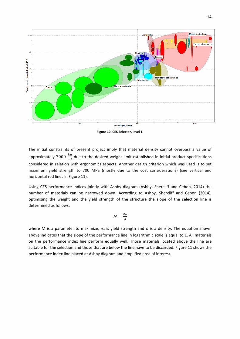
The" initial" constraints" of" present" project" imply" that" material" density" cannot" overpass" a" value" of"
approximately"7000! !"!!"due" to" the"desired"weight" limit"established" in" initial"product" specifications"
considered" in" relation"with" ergonomics" aspects." Another" design" criterion"which"was"used" is" to" set"
maximum" yield" strength" to" 700" MPa" (mostly" due" to" the" cost" considerations)" (see" vertical" and"
horizontal"red"lines"in"Figure"11).""
Using" CES" performance" indices" jointly"with" Ashby" diagram" (Ashby," Shercliff" and" Cebon," 2014)" the"
number" of" materials" can" be" narrowed" down." According" to" Ashby," Shercliff" and" Cebon" (2014),"
optimizing" the" weight" and" the" yield" strength" of" the" structure" the" slope" of" the" selection" line" is"
determined"as"follows:"
! = !!! ""
where"M" is" a" parameter" to"maximize,"!!!is" yield" strength" and"!" is" a" density." The" equation" shown"above"indicates"that"the"slope"of"the"performance"line"in"logarithmic"scale"is"equal"to"1."All"materials"
on" the" performance" index" line" perform" equally" well." Those" materials" located" above" the" line" are"
suitable"for"the"selection"and"those"that"are"below"the"line"have"to"be"discarded."Figure"11"shows"the"
performance"index"line"placed"at"Ashby"diagram"and"amplified"area"of"interest.""
"
"
"
"
"
Figure!10.!CES!Selector,!level!1.!

"
"
"
15"
"
"
"
"
"
"
"
"
"
"
From"Figure"11"it"can"be"observed"that"possible"candidates"to"materials"are"aluminium"alloys."Since"
two"important"characteristics"regarding"the"design"are"strength"and"weight"it"seems"like"aluminium"
alloys"can"be"a" right"choice"also" from"the"cost"perspective."Also,"as" in"existing"CRS"study," it"can"be"
observed"that"aluminium"alloys" is"an"appropriate"type"of"material" to"employ"due"to" its"mechanical"
properties" as"well" as" prices" in" comparison"with"other" possible" solutions" such" as" CFPR,"magnesium"
alloys,"titanium"alloys,"etc."Figure"12"shows"the"aluminium"alloys"group."
"
"
""
"
"
"
"
"
"
"
"
"
Figure!11.!CES!Selector,!performance!index!slope,!level!3.!
Figure!12.!CES!Selector,!level!3.!Aluminium!alloys.!

"
"
"
16"
"
"
"
"
"
"
"
"
"
"
Figure"11"and"Figure"12"indicate"three"best"alternatives"that"were"picked"up"regarding"yield"limit"and"
price" per" kilogram" of"material." These" three" alternatives" are" aluminium" alloy" 2024" T36," aluminium"
alloy"6010"T6"and"aluminium"alloy"5083"H38."All"three"have"similar"properties"but"finally"Al"2024"T36"
was" chosen" to" carry" out" the" design" and" simulations" due" to" its" acceptable"welding" properties" and"
machinability." This" alloy" is" hardened" by" precipitation" with" solution" heat" treatment" and" then" cold"
worked"by"a"reduction"of"5I6%!(Chandler,"1996)."Figure"14"shows"the"stressIstrain"curve"for"Al"2024"T36"as"based"on"ASM"International"(2002).
"
"
"
"
"
"
"
"
"
"
"
"
"
"
"
"
"
"
Other" relevant"mechanical" properties" are:" Young’"Modulus"of" 73.8"GPa"and"Poisson" ratio"of" 0.337"
(ASM"International,"2002.,"Chandler,"1996).""
"
Figure!13.!CES!Selector,!level!3.!Aluminium!alloys,!costs.!
Figure!14.!Al!2024!T36!true!stressMtrue!strain!curve.!
"
"
"
17"
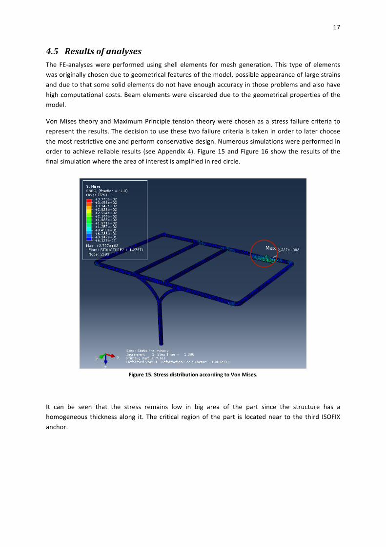
4.5 Results!of!analyses!The" FEIanalyses"were" performed" using" shell" elements" for"mesh" generation." This" type" of" elements"
was"originally"chosen"due"to"geometrical"features"of"the"model,"possible"appearance"of"large"strains"
and"due"to"that"some"solid"elements"do"not"have"enough"accuracy"in"those"problems"and"also"have"
high"computational"costs."Beam"elements"were"discarded"due"to"the"geometrical"properties"of" the"
model.""
Von"Mises"theory"and"Maximum"Principle"tension"theory"were"chosen"as"a"stress"failure"criteria"to"
represent"the"results."The"decision"to"use"these"two"failure"criteria"is"taken"in"order"to"later"choose"
the"most"restrictive"one"and"perform"conservative"design."Numerous"simulations"were"performed"in"
order" to"achieve" reliable" results" (see"Appendix"4)." Figure"15"and"Figure"16" show"the" results"of" the"
final"simulation"where"the"area"of"interest"is"amplified"in"red"circle."
"
"
!
!
!
!
!
!
!
!
!
!
It" can" be" seen" that" the" stress" remains" low" in" big" area" of" the" part" since" the" structure" has" a"
homogeneous" thickness" along" it." The" critical" region" of" the" part" is" located" near" to" the" third" ISOFIX"
anchor."
!
!
"
Figure!15.!Stress!distribution!according!to!Von!Mises.!

"
"
"
18"
"
"
"
"
"
"
"
"
"
"
"
"
It"can"be"observed"from"the"results"that" in"both"cases"the"maximum"stress"remains" lower"than"the"
material’s"yield"strength."Moreover,"the"maximum"stress"value"occurs"at"a"stress"concentration"due"
to" proximity" to" the" sharp" corner" in" the" structure" as" well" to" the" boundaries." A" further" simulation"
without"sharp"edges"was"then"performed"proving"that"the"removal"of"these"sharp"edges"eliminated"
the"stress"concentrations"giving"the"actual"stress"level"as"it"is"shown"in"Figure"17."
"
"
"
"
"
"
"
"
"
"
"
"
Figure!17.!Stress!distribution!without!sharp!edges,!Von!Mises.!
Figure!16.!Stress!distribution!according!to!max.!principle!stress.!

"
"
"
19"
The" location" of"maximum" stress" in" Figure" 17" remains" close" to" the" shown" in" Figure" 16" due" to" the"
boundary"proximity,"however" its"value" is" lower"as"then" is"no"more"sharp"edge"that"can" lead"to"the"
poor"FEIprediction2.""
The"final"simulations"were"performed"using"generalIpurpose"shell"elements:"S8R"(stress,"quadratic,"8I
node" shell" element" with" reduced" integration)" and" S4R" (stress," linear," 4Inode" shell" element" with"
reduced" integration)." Figure" 20" shows" an" S8R" element." The" S4R" element" has" the" same" form" but"
without"middle"nodes."The"mesh"can"be"observed"at"Figure"18"and"Figure"19."Since"the"use"of"fully"
integrated" elements" can" lead" to" surface" locking" and" as" a" result" excessive" stiffness," a" reduced"
integration" was" needed" to" provide" more" realistic" results." Reduced" integration" can" cause"
hourglassing3," however," ABAQUS" has" an" hourglass" control" mechanism" for" linear" elements" and" in"
quadratic"elements"hourglassing"does"not"propagate"and"has"less"effect"(Yang"et."Al.,"2000).""
"
"
"
"
"
"
"
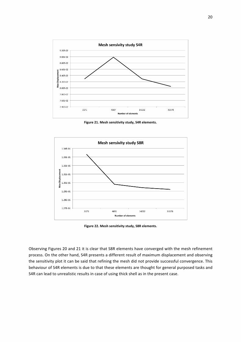
A"mesh"refinement"and"mesh"sensitivity"study"were"carried"out"in"order"to"check"the"accuracy"of"the"
achieved"results" (see"Figure"21"and"Figure"22)."The"simulations"started"with"an"elements"size"of"20"
mm" (3171" elements)" followed" by" mesh" refinement" to" 10" mm" (4691" elements)," 5" mm" (14232"
elements)" and" 3" mm" (31578" elements)." A" more" detailed" examination" of" performed" simulations"
(iterations"and"mesh"refinement"process)"can"be"found"in"Appendix"4."
"
"
"
"
"
"
"
"""""""""""""""""""""""""""""""""""""""""""""""""""""""""""""2"Refining"a"mesh"around"stress"concentrations"can"lead"to"higher"values"of"stress"as"the"element"model"
progressively"sharper"details"increasing"the"maximum"accordingly."3"This"mesh"instability"is"related"to"zeroIenergy"modes"in"which"displacements"do"not"lead"to"any"strain"or"
stress"at"the"integration"points."
Figure!20.!8Mnode!shell!element!(S8/S8R),!(MIT,!2014).!
Figure!18.!Mesh!of!the!part.! Figure!19.!Mesh!of!the!part,!close!detail.!
"
"
"
20"
"
"
"
"
"
"
"
"
"
"
"
"
"
"
"
"
"
"
"
"
"
Observing"Figures"20"and"21"it"is"clear"that"S8R"elements"have"converged"with"the"mesh"refinement"
process."On"the"other"hand,"S4R"presents"a"different"result"of"maximum"displacement"and"observing"
the"sensitivity"plot"it"can"be"said"that"refining"the"mesh"did"not"provide"successful"convergence."This"
behaviour"of"S4R"elements"is"due"to"that"these"elements"are"thought"for"general"purposed"tasks"and"
S4R"can"lead"to"unrealistic"results"in"case"of"using"thick"shell"as"in"the"present"case."
"
"
"
Figure!22.!Mesh!sensitivity!study,!S8R!elements.!
Figure!21.!Mesh!sensitivity!study,!S4R!elements.!
"
"
"
21"
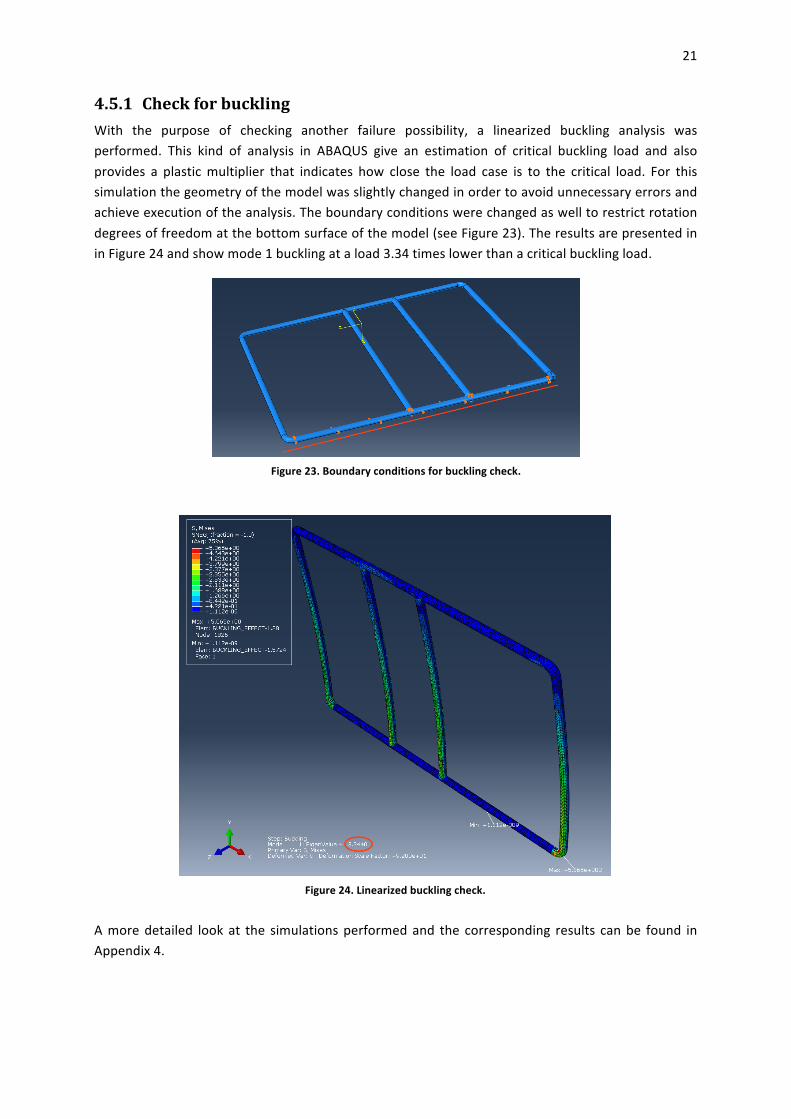
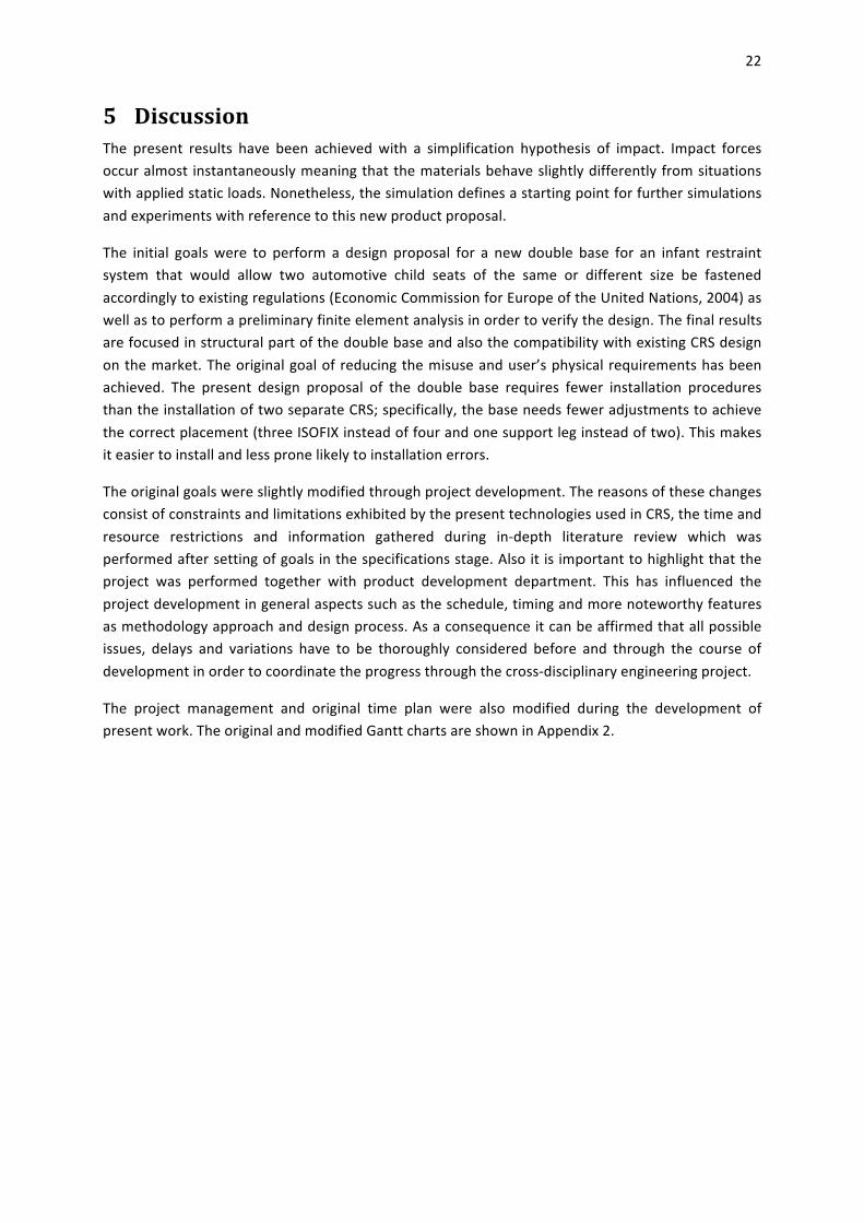
4.5.1 Check!for!buckling!With" the" purpose" of" checking" another" failure" possibility," a" linearized" buckling" analysis" was"
performed." This" kind" of" analysis" in" ABAQUS" give" an" estimation" of" critical" buckling" load" and" also"
provides" a" plastic"multiplier" that" indicates" how" close" the" load" case" is" to" the" critical" load." For" this"
simulation"the"geometry"of"the"model"was"slightly"changed"in"order"to"avoid"unnecessary"errors"and"
achieve"execution"of"the"analysis."The"boundary"conditions"were"changed"as"well"to"restrict"rotation"
degrees"of"freedom"at"the"bottom"surface"of"the"model"(see"Figure"23)."The"results"are"presented"in"
in"Figure"24"and"show"mode"1"buckling"at"a"load"3.34"times"lower"than"a"critical"buckling"load.""
"
"
"
"
"
"
"
"
"
"
"
"
"
"
"
"
"
"
"
A"more"detailed" look"at" the" simulations"performed"and" the" corresponding" results" can"be" found" in"
Appendix"4."
"
Figure!24.!Linearized!buckling!check.!
Figure!23.!Boundary!conditions!for!buckling!check.!
"
"
"
22"
5 Discussion!The" present" results" have" been" achieved"with" a" simplification" hypothesis" of" impact." Impact" forces"
occur"almost" instantaneously"meaning"that"the"materials"behave"slightly"differently"from"situations"
with"applied"static"loads."Nonetheless,"the"simulation"defines"a"starting"point"for"further"simulations"
and"experiments"with"reference"to"this"new"product"proposal."
The" initial" goals"were" to" perform" a" design" proposal" for" a" new" double" base" for" an" infant" restraint"
system" that" would" allow" two" automotive" child" seats" of" the" same" or" different" size" be" fastened"
accordingly"to"existing"regulations"(Economic"Commission"for"Europe"of"the"United"Nations,"2004)"as"
well"as"to"perform"a"preliminary"finite"element"analysis"in"order"to"verify"the"design."The"final"results"
are"focused"in"structural"part"of"the"double"base"and"also"the"compatibility"with"existing"CRS"design"
on"the"market."The"original"goal"of"reducing"the"misuse"and"user’s"physical"requirements"has"been"
achieved." The" present" design" proposal" of" the" double" base" requires" fewer" installation" procedures"
than"the"installation"of"two"separate"CRS;"specifically,"the"base"needs"fewer"adjustments"to"achieve"
the"correct"placement"(three"ISOFIX"instead"of"four"and"one"support"leg"instead"of"two)."This"makes"
it"easier"to"install"and"less"prone"likely"to"installation"errors."
The"original"goals"were"slightly"modified"through"project"development."The"reasons"of"these"changes"
consist"of"constraints"and"limitations"exhibited"by"the"present"technologies"used"in"CRS,"the"time"and"
resource" restrictions" and" information" gathered" during" inIdepth" literature" review" which" was"
performed"after"setting"of"goals"in"the"specifications"stage."Also"it"is"important"to"highlight"that"the"
project" was" performed" together" with" product" development" department." This" has" influenced" the"
project"development"in"general"aspects"such"as"the"schedule,"timing"and"more"noteworthy"features"
as"methodology"approach"and"design"process."As"a"consequence"it"can"be"affirmed"that"all"possible"
issues," delays" and" variations" have" to" be" thoroughly" considered" before" and" through" the" course" of"
development"in"order"to"coordinate"the"progress"through"the"crossIdisciplinary"engineering"project."
The" project" management" and" original" time" plan" were" also" modified" during" the" development" of"
present"work."The"original"and"modified"Gantt"charts"are"shown"in"Appendix"2."
"
"
"
"
"
"
"
"

"
"
"
23"
6 Conclusions!A" novel" and" new" concept" of" a" double" base" for" an" automotive" infant" restraint" system" has" been"
developed."Its"design"is"supported"by"market"research"of"the"possible"social"benefits"that"come"from"
design’s" advantages"when" compared"with" existing" products." Installation" errors" by" the" parents" are"
likely"to"be"reduced"therefore"improving"the"safety."
! The" environmental" aspects" are" addressed" with" adequate" material" selection" which" was"
performed"with"concerns"about"manufacturing,"material"operation"and"use."
! Taking" into"account"a"mesh" convergence" study," the" solution" can"be" considered" sufficiently"
accurate" for" further" design" iterations." S8R" elements" gives" better" values" with" less" mesh"
refinement"due"to"quadratic"nature"of"the"elements"in"the"values"of"displacement"field"and"
use"of"more"integration"points"per"element."The"displacements"show"that"the"strain"is"elastic,"
however"it"was"verified"by"a"nonIlinear"analysis."
! The"stress" level"remains"below"the"yield" limit"thus"the"structure"will"not"collapse"under"the"
present" load" case." The" critical" buckling" load" is" higher" than" the" applied" load" therefore" the"
structure"will"not"buckle."The"necessary"thickness"to"withstand"the"impact"force"for"a"frontal"
impact"according"to"Economic"Commission"for"Europe"of"the"United"Nations"(2004)"testing"is"
5"mm"with"a"20"mm"outer"diameter"tubular"structure.""
! According" to" the" preliminary" analysis," the" proposed" design" of" the" structural" frame" for" a"
double" base" CRS" is" feasible" and" can" be" manufactured" by" currently" used" manufacturing"
methods"for"aluminium"alloys.""
"
"
"
"
"
"
"
"
"
"
"
"
"

"
"
"
24"
7 Future!work!Due" to" preliminary" nature" of" the" analysis" employed" in" this" project," a" dynamic," nonIlinear" analysis"
should"be" carried"out"under" the" conditions"prescribed"by"Economic"Commission" for" Europe"of" the"
United"Nations"(2004)"in"order"to"achieve"a"more"reliable"model"of"the"real"case.""With"respect"to"the"
compatibility" of" the" base" with" existing" CRS" designs" of" current" manufacturers," it" is" particularly"
interesting" to" design" a" CRS" basket" specifically" aimed" at" this" double" base."With" respect" to" the" FEI
mesh," elements" used" in" present" work" well" but" a" more" in" depth" and" detailed" analysis" with" an"
improved"geometry"of"the"FEImodel"should"be"performed."
Finally,"to"achieve"a"definitive"double"base"design"that"could"be"distributed"to"final"users"it"is"critical"
to" develop" a" prototype" of" the" double" base" and" carry" out" experimental" testing" in" accordance"with"
Economic"Commission"for"Europe"of"the"United"Nations"(2004)"in"order"to"get"a"detailed"information"
about"load"effects"on"children."
"
"
"
"
"
"
"
"
"
"
"
"
"
"
"
"
"
"
"

"
"
"
25"
References!"
About.com,"(2010)."How$to$install$an$infant$car$seat."[Online]"Available"at:"""HYPERLINK""https://www.youtube.com/watch?v=SJ09iMCpJso""[Accessed"24"January"2015]."
Altenhof,"W."&"Turchi,"R.,"(2004)."A$Numerical$Investigation$into$HIC$and$Nij$of$Children$for$Forward$and$Rearward$Facing$Configurations$in$a$child$Restraint$System."In"8th"International"LSIDYNA"Users"
Conference."Crash/Safety."
Anund,"A."et"al.,"(2003)."Child$safety$in$cars."Linköping,"Sweden:"Swedish"National"Road"and"Transport"Institute."
Ashby,"M.,"Shercliff,"H.,"Cebon,"D.,(2014)"Materials:$engineering,$science,$processing$and$design;$North$American$Edition$."Third"Edition."ButterworthIHeinemann."
ASM"International,."(2002)."Atlas$of$stressDstrain$curves"(2nd"ed.)."ASM"International."
"
Baranowski,"P."et"al.,"(2014)."A$child$seat$numerical$model$validation$in$a$static$and$dynamic$work$conditions."[Online]"Available"at:"""HYPERLINK""http://dx.doi.org/10.1016/j.acme.2014.07.001""""""
http://dx.doi.org/10.1016/j.acme.2014.07.001"."
Besafe,"(2015)."Izi$Kid$IDsize"[Online]"Available"from:"http://www.besafe.com/en/carIseatI
products/toddlersIcarIseatI0I18I0I25kg/iziIkidIiIsize#"[Accessed:"15th""January"2015"]"
Britax,"(2015)."What$is$ISOFIX?"[Online]"Available"from:"
http://www.britaxthailand.com/ISOFIX/chooseIaIpage.html"[Accessed:"4th"March"2015]"
CarSeatBlog,"(2012)."Graco$SnugRide$35$Infant$Carseat$Review:$4th$Generation$is$a$Homerun!"[Online]"Available"form:"http://carseatblog.com/16957/gracoIsnugrideI35IinfantIcarseatIreviewI4thI
generationIisIaIhomerun/"[Accessed:"3rd"March"2015]"
Chandler)H,)(1996).# Heat$Treater's$Guide:$Practices)and)Procedures)for)Nonferrous)Alloys .$ASM$International.+ "
ConsumerReport."(2015)."Dimensions:$Seating$Capacity."[Online]"Available"from:"
http://www.consumerreports.org/cro/cars/types/seatingIcomparison.htm"[Accessed:"5th"March"
2015]"
Cross,"N."(2008)"Engineering$Design$Methods.$Strategies$for$Product$Design."Fourth"Edition."Willey."
Economic" Commission" for" Europe" of" the" United" Nations,.(2004).Regulation$ no.$ 44.$ Uniform$provisions$concerning$the$approval$of$restraining$devices$for$child$occupants$of$power$driven$vehicles$(child$restraint$systems)."Official"Journal"of"the"European"Union."
Focus2move,"(2015)."The$100$Best$Selling$Cars$in$Europe$–$full$year$2014$ranking"[Online]"Available"from:"http://focus2move.com/100IbestIsellingIcarsIinIeurope/"[Accessed:"1
st"March"2015]"

"
"
"
26"
Ford."(2015)."Ford$Fiesta$Owner’s$Manual."[Online]"Available"from:"
http://www.fordservicecontent.com/Ford_Content/Catalog/owner_information/2015IFiestaI
OwnersIManualIversionI2_om_ENIUS_09_2014.pdf"[Accessed:"5st"March"2015]"
Honda."(2015)."Honda"Civic"2015"Owner’s"Manual."[Online]"Available"from:"
http://techinfo.honda.com/rjanisis/pubs/QS/AH/ATR01515OG/enu/ATR01515OG.pdf"[Accessed:"1st"
March"2015]!Kapoor,"T.,"Altenhof,"W."&"Howard,"A.,"(2005)."The$effect$of$using$universal$anchorages$in$child$restraint$seats$on$the$injury$potential$for$children$in$frontal$crash."IJCrash,"10(3),"pp.305I14."
Kapoor,"T."et"al.,"(2011)."A$numerical$investigation$into$the$effect$of$CRS$misuse$on$the$injury$potential$of$children$in$frontal$and$side$impact$crashes."Accident"Analysis"and"Prevention,"43,"pp.1438I50."
Langwieder,"K.,"Hummel,"T."&"Roselt,"T.,"(2003)."ISOFIX$–$possibilities$and$problems$of$a$new$concept$for$child$restraint$systems."IJCrash$,"8(5),"pp.443I54."
Lund,"U.J.,"(2005)"The$effect$of$seating$location$on$the$injury$of$properly."Accident"Analysis"and"Prevention,"Issue"37,"pp."435–439."
Mazda."(2014)."Mazda$3,$5Ddoor$Owner’s$Manual."[Online]"Available"from:"
https://www.mymazda.com/MusaWeb/pdf/manuals/2014_MAZDA3_OM.pdf"[Accessed:"5th"March"
2015]"
McDill,"M;"Personal$Communication,"(2015),"22"February."Skövde,"Sweden.""
Pitcher,"M.,"Hynd,"M."&"Onyekwere,"J.,"(2011)."National$Database$for$Child$Restraint$Use."
Renault."(2015).Renault$Clio$Features$and$Specifications.$[Online]"Available"from:"
http://www.renault.com.au/vehicles/cars/clio/clio/featuresIspecifications"[Accessed:"3rd"March"
2015]"
Shivakumar,K.,N.,"Elber"W.,"W.,"Illg"W.,W.,"(1985)."Prediction$of$Impact$Force$and$Duration$Due$to$LowDVelocity$Impact$on$Circular$Composite$Laminates."ASME."Journal"of"Applied"Mechanics,"52(3),"
pp."674I680"
Testa,"M.,"(2011)."Family$Sizes$in$Europe:$Evidence$from$the$2011."Eurobarometer"Survey"[Online]"
Available"at:"http://www.oeaw.ac.at/vid/download/edrp_2_2012.pdf"[Accessed:"3rd"March"2015]"
Toyota."(2015)."Toyota$Yaris$2015$Owner’s$Manual.[Online]"Available"from:"
https://carmanuals2.com/get/toyotaIyarisI2015IownerIsImanualI38074."[Accessed:"5th"March"2015]"
Wang,"Q."et"al.,"(2007)."Child$restraint$seat$design$considerations$to$mitigate$injuries$to$threeDyearDold$children$in$side$impact$crashes."International"Journal"of"Crashworthiness,"12(6),"pp.629I44."
Yang,"H."T."Y.,"Saigal,"S.,"Masud,"A."and"Kapania,"R."K.,"(2000)."A$survey$of$recent$shell$finite$elements.$International$Journal$for$Numerical$Methods$in$Engineering,"47,"pp."101–127."
"

27"
"
" "
Appendix(1.(Work(breakdown!Figure"25"shows"the"work"breakdown"diagram"identifying"parts"which"were"done"through"the"project"
development."The"detailed"study"of" regulations," load"case,"boundary"conditions,"material" selection"
and"preforming"of"FEIanalysis"were"executed"exclusively"by"the"mechanical"engineering"department"
and" presented" in" this" report." The" ergonomic" study," market" research," surveys" and" compatibility"
analysis" were" performed" exclusively" by" the" product" development" department." The" stages" of" the"
literature" study," existing" CRS" analysis," automotive" fixture" analysis" and" the" design" process" where"
performed"jointly"by"both"departments."
!Figure!25.!Work!breakdown!diagram.!
!"
"
"
"
"
"
"
"

"
"
"
28"
Appendix(2.(Time(plan.!This" section"presents" the"original" time"plan" elaborated" as" part" of" project"management" task" in" the"
beginning" of" the" project" development" as" well" the" time" plan" modifications" resulted" from" the"
addressed" in"discussion"section"of"the"report."Special"mention"has"to"be"made"to"tasks"such"as"the"
literature"study,"running"of"simulations,"approach"and"geometry"determination,"which"have"taken"far"
more" time" than"expected." Some"of" these" tasks"were" critical" in"order" to"achieve"main"goals"of" this"
work." Figure" 26" shows" the" original" Gantt" chart" and" Figure" 27" represents" the"modified" version" of"
Gantt"chart"with"activities"that"took"more"time"than"expected"marked"in"red"(critical"tasks"in"project"
development),"yellow"and"orange."
"
Figure!26.!Original!Gantt!chart!and!time!plan.!
"
Figure!27.!Updated!Gantt!chart!and!time!plan.!
!
!"

"
"
"
29"
Appendix(3.!Drawings!and$final$product$presentation!In"this"section"a"detailed"drawing"of"the"structural" frame"is"presented"for"the"preliminary"design"of"
the" new" double" base." The" dimensions," the" shape" and" the" details" are" shown" in" the" Figure" 31." All"
shown"dimensions"are"in"millimetres."Figures"28,"29"and"30"show"the"final"product"representation."
"
Figure!28.!Representation!of!the!final!product.!Back!view.!
"
Figure!29.!Representation!of!the!final!product.!
"
Figure!30.!InMcar!represenation!of!the!final!product.!

"
"
"
30"
"
Figure!31.!Technical!drawing!of!the!structure!of!the!double!base.!
Model file nam
eS
cale
Draw
ing file name
Sheet(s)
LoginA
pproved by (teacher signature)
View
placement
Made by
R25
20
510
900
272.5200
40
R208
110
2508
4425
R12
R2
R0.6
15
10
STR
UC
TUR
E3
0.100
DR
W0006
1(1)
Nikita P
opov Popov
a00login

"
"
"
31"
Appendix(4.(Results(of(simulations!In" present" section," more" detailed" information" about" the" results" of" all" performed" simulation" is"
presented.""
Firstly"two"types"of"elements"were"chosen"for"the"simulations:"shell"elements"S4"and"shell"elements"
S8" (see" Figures" 32," 33," 34," and" 35)." The" achieved" results" of" using" these" elements" have" shown" a"
noticeable"difference" in"stress"values."Employing"elements"without"reduced" integration" in"this"type"
of" problem"may" lead" to" the" shear" locking" effects" in" elements" providing" inexistent" stiffness" to" the"
model" which" means" lower" stress" and" displacements" than" actual" ones." Further" simulations" were"
carried" out" using" shell" elements"with" reduced" integration:" S4R" (with" automatic" hourglass" control)"
and"S8R"(secondIorder"elements,"hourglassing"is"not"propagated).""
The"achieved"results" in"terms"of"maximum"displacement"and"maximum"stress"are"shown"in"Figures"
37" to" 41." The" simulations" performed" with" S8" shell" elements" have" a" higher" maximum" stress" in"
proximity"of"boundary"conditions"and"stress"concentrations"(sharp"edges)."Therefore,"geometry"with"
suppressed" stress" concentrations" was" used" in" following" iterations." The" final" results" (in" the"model"
without"sharp"edges"can"be"found"in"Figures"42,"43"and"44)."
"
"
Figure!32.!Stress!distribution,!Von!Mises,!S4!elements.!

"
"
"
32"
Figure!33.!Stress!distribution,!Max.!Principle.!S4!elements.!
Figure!34.!Max.!displacement,!S4!elements.!

"
"
"
33"
"
Figure!35.!Stress!distribution,!Von!Mises,!S8!elements.!
Figure!36.!Max.!Displacement,!S8!elements.!

"
"
"
34"
"
Figure!37.!Stress!distribution,!Von!Mises,!S4R.!
"
Figure!38.!Stress!distribution,!Max.!Principles,!S4R.!

"
"
"
35"
"
Figure!39.!Max.!displacement,!S4R.!
"
Figure!40.!Stress!distribution,!Von!Mises,!S8R.!

"
"
"
36"
Figure!41.!Max.!displacement,!S8R.!
!
Figure!42.!Stress!distribution,!Von!Mises,!S8R,!without!stress!concentrations.!

"
"
"
37"
Figure!43.!Stress!distribution,!Max.!Principles,!S8R,!without!stress!concentrations.!
Figure!44.!Max.!displacement,!S8R,!without!stress!concentrations.!

"
"
"
38"
S4R!and!S8R!comparison!and!mesh!convergence!As"it"was"explained"in"the"report"the"mesh"refinement"was"performed"starting"with"element"size"of"
20mm"and"decreasing"to"10"mm,"5"mm"and"3mm."Tables"2"and"3"show"a"mesh"sensitivity"o"mesh"
convergence"study."As"can"be"observed,"S4R"elements"have"not"converged"meanwhile"S8R"elements"
show"a"strong"indication"of"convergence."S4R"elements"behaviour"is"due"to"the"thickness"of"the"shell"
elements,"according"to"ABAQUS"user’s"manual,"if"the"thickness"is"more"than"1/15"of"characteristic"
surface"length"a"thick"shell"elements"(S8R"and"S8RT)"will"give"better"results."Besides"that"S8R"
elements"are"smallIstrain"elements"and"suits"better"the"present"case."
Table"A4.1."Mesh"convergence"S4R"elements"
Element"size"(element"
number)"
Max."disp."value" Von"Mises"max."
stress"
Max."Principle"max."
stress"
20"mm" 8.295eI2"" 1.785"e+2" 1.465e+2"
10"mm" 8.984eI2" 2.120e+2" 2.227e+2"
5"mm" 8.291eI2" 2.245e+2" 2.566e+2"
3"mm" 8.049eI2" 2.727e+2" 3.078e+2"
"
Table"A4.2."Mesh"convergence"S8R"elements."
Element"size"(element"
number)"
Max."disp."value" Von"Mises"max."
stress"
Max."Principle"max."
stress"
20"mm" 1.333eI1"" 2.785"e+2" 3.063e+2"
10"mm" 1.298eI1" 2.520e+2" 2.765e+2"
5"mm" 1.294eI1" 2.249e+2" 2.487e+2"
3"mm" 1.292eI1" 2.237e+2" 2.415e+2"
"
Also"a"nonIlinear"check"was"performed"in"order"to"verify"small"strains"in"the"model."The"simulations"
performed"with"nonIlinear"effects"provided"very"similar"results"meaning"that"the"linearized"
simulations."The"strain"values"were"found"below"the"elastic"limit"of"material."""
"
Linearized!buckling!check!In"following"(Figures"45"to"48)"all"four"modes"of"buckling"are"shown"with"corresponding"plastic"
multipliers."It"can"be"affirmed"that"the"first"mode"(Figure"45)"is"the"most"dangerous"due"to"the"plastic"
multiplier"is"lower"than"in"other"3"cases.""

"
"
"
39"
"
Figure!45.!Buckling!mode!1.!
"
Figure!46.!Buckling!mode!2.!

"
"
"
40"
"
Figure!47.!Buckling!mode!3.!
"
Figure!48.!Buckling!mode!4.!!