infn milano bicocca
TRANSCRIPT

1SLO, 25 March 2010
ELECTRONICS
INFN Milano BicoccaFeaturing:
Claudio Arnaboldi;
Andrea Giachero;
Claudio Gotti
Gianluigi Pessina;
and also:
Alessandro Bau (partial);
Andrea Passerini (partial).
2SLO, 25 March 2010
In Shortly
Summary of the Electronic Review of the last December in Berkeley;
State of the Electronic system:
Production;
design
Testing.

3SLO, 25 March 2010
Electronic Review (I)
A review has been made on December 9 and 10 in Berkeley.
DOE asked for 3 experts in Berkeley.
(Bryant, Freedman and Kadel were also present)
Reports were from:
Gianluigi (with Claudio) on the Electronic Project;
Frank about the production and founding;
Huan about testing.
The project is mature;
Investigation of the observed anomalies on some channels with the pulser;
provide details about the founding needs;
provide details on the testing procedures.
Conclusive remarks:

4SLO, 25 March 2010
Electronic Review (II)
The 3 hours reports can be found at:
Or navigating from:
http://pessina.mib.infn.it
http://crio.mib.infn.it/wig/electronics/

5SLO, 25 March 2010
Electronic System Scheme
Bias and Load Res.
Pre SS
X6
Main board
Pro. Logic
Backplane
Bias and Load Res.
Pre SS
X6
Main board
Pro. Logic
Backplane Bessel Filter
x12
Pro. LogicBackplane
Bessel Filter
x12
Pro. LogicBackplane
Linear Low no. Power
supply
Pre. Reg.
(Switc.)
48 V Switc. Reg.
Linear Low no. Power
supply
Pre. Reg.
(Switc.)
48 V Switc. Reg.
K =Kapton
Mixing CamberK
= PEN =Costantan
K =KaptonK =Kapton
Mixing CamberK
= PEN= PEN =Costantan=Costantan
Detector Very front-end
Antialiasing
Power supply systemHeather Pulse
Gen.
Calibration Pulse Gen.
Small Faraday Cages
Top of the refr.
Close to the DAQ
DAQ
Links to the detectors: PEN and glue Kapton boards.

6SLO, 25 March 2010
Detector Link (I)
K =Kapton
Mixing CamberK
= PEN =Costantan
K =KaptonK =Kapton
Mixing CamberK
= PEN= PEN =Costantan=Costantan
Detector
Links to the detectors: PEN and glue Kapton boards.
The PEN tapes link system from the Mixing chamber down to the detectors and the heaters has been fully designed for both CUORE and CUORE0.
PEN tapes for CUORE0 will be available starting from the next week;
Test tapes or CUORE in various geometry will be also available by that time.

7SLO, 25 March 2010
Detector Link (II)We have arranged the production in order to have the tapes cleaned and packaged under vacuum at the production stage.
The cleaning has been made using our selected tissue and propilic-alcohol.

8SLO, 25 March 2010
Detector Link (III)
K =Kapton
Mixing CamberK
= PEN =Costantan
K =KaptonK =Kapton
Mixing CamberK
= PEN= PEN =Costantan=Costantan
Detector
Links to the detectors: PEN and glue Kapton boards.
Considerations:
1. With respect to the original layout, room has been added to some tapes at their bottom for the implementation of thermometers able to measure the far location of the detector frame. These thermometer have to be low-radiation compliant.
2. On some Kapton boards, one per column, room has been made available to add 5 differential connections for the readout of thermometers and the like.
9SLO, 25 March 2010
Very Front-end: Preamplifier
K =Kapton
Mixing CamberK
= PEN =Costantan
K =KaptonK =Kapton
Mixing CamberK
= PEN= PEN =Costantan=Costantan
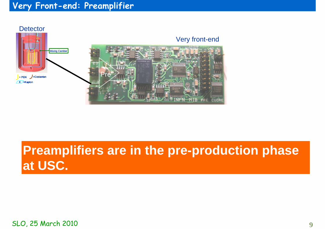
DetectorVery front-end
Pre
Preamplifiers are in the pre-production phase at USC.

10SLO, 25 March 2010
Very Front-end: Main board
K =Kapton
Mixing CamberK
= PEN =Costantan
K =KaptonK =Kapton
Mixing CamberK
= PEN= PEN =Costantan=Costantan
DetectorVery front-end
Pre PGA
Completed
Main board
Detector biasing+Load resistors
Completed

11SLO, 25 March 2010
Very Front-end: Main board
K =Kapton
Mixing CamberK
= PEN =Costantan
K =KaptonK =Kapton
Mixing CamberK
= PEN= PEN =Costantan=Costantan
Detector
Main board
The layout of the board is starting.

12SLO, 25 March 2010
The calibrating pulse generator (I)
K =Kapton
Mixing CamberK
= PEN =Costantan
K =KaptonK =Kapton
Mixing CamberK
= PEN= PEN =Costantan=Costantan
Detector
Heather Pulse Gen.
Calibration Pulse Gen.
The calibrating pulse generator upgrade is under development.
The firmware and the switching part of this instrument has been completed.
Its characterization is under way with good results.

13SLO, 25 March 2010
The calibrating pulse generator (II)
K =Kapton
Mixing CamberK
= PEN =Costantan
K =KaptonK =Kapton
Mixing CamberK
= PEN= PEN =Costantan=Costantan
Detector
Heather Pulse Gen.
Calibration Pulse Gen.
The calibrating pulse generator upgrade is under development.
The firmware and the switching part of this instrument has been completed.
Its characterization is under way with good results.

14SLO, 25 March 2010
The calibrating pulse generator (III): pulse width stability
Widthy = 2,982E-04x + 9,000E+02
R2 = 9,943E-01
899,992
899,994
899,996
899,998
900,000
900,002
900,004
900,006
900,008
900,010
900,012
0 10 20 30 40 50 60T (°C)
Wid
th (
s)
Tw (µs)Lineare (Tw (µs))
Temperature dependenceof pulse width

15SLO, 25 March 2010
The calibrating pulse generator (IV): pulse width stability
Width
Temperature dependenceof pulse width:
<0.5 ppm/°C
y = 0,3314x - 8,0077R2 = 0,9943
-10
-8
-6
-4
-2
0
2
4
6
8
10
0 10 20 30 40 50 60
T (°C)
Wid
th c
hang
e (p
pm)
ppm/°CLineare (ppm/°C)

16SLO, 25 March 2010
The calibrating pulse generator (V): pulse width stability
Width
Jitter of pulse width:
<0.7 ppm,
With temperature:
0.0032 ppm/°C
y = 0,0032x + 0,5636R2 = 0,9945
0
0,1
0,2
0,3
0,4
0,5
0,6
0,7
0,8
0 10 20 30 40 50 60T (°C)
Jitte
r (pp
m)
Jitter (ppm/°C)
Lineare (Jitter(ppm/°C))

17SLO, 25 March 2010
Supply voltage system
Linear Low no. Power
supply
Pre. Reg.
(Switc.)
48 V Switc. Reg.
Linear Low no. Power
supply
Pre. Reg.
(Switc.)
48 V Switc. Reg.
K =Kapton
Mixing CamberK
= PEN =Costantan
K =KaptonK =Kapton
Mixing CamberK
= PEN= PEN =Costantan=Costantan
Detector
Power supply system
The DC-DC design of the power supply system is finishing (thanks to the support from Alessandro Bau and Andrea Passerini). It can be controlled and configured remotely like the other devices.A prototype is under development.
The linear ultra-low drift and low-noise supply voltage is going to be upgraded.

18SLO, 25 March 2010
Antialiasing Filter
Bias and Load Res.
Pre SS
X6
Main board
Pro. Logic
Backplane
Bias and Load Res.
Pre SS
X6
Main board
Pro. Logic
Backplane
K =Kapton
Mixing CamberK
= PEN =Costantan
K =KaptonK =Kapton
Mixing CamberK
= PEN= PEN =Costantan=Costantan
Detector Very front-end
Top of the refr.
Bessel Filter
x12
Pro. LogicBackplane
Done
The back plane is with USC for final production.
The Filtering Boards are with USC for prototype.
The design of the Antialiasing filter has been completed (both Analog, Digital and Firmware).
has been developed
DONE

19SLO, 25 March 2010
Digital data link
A CAN bus based optical data link has been developed and tested for the control of the electronic system.
The link is either Linux and Window OS compatible.

20SLO, 25 March 2010
Production Precautions
It is mandatory to ask:
PCB producer: electrical test.
PCB population:
Automatic Visual inspection test;
In Circuit Test, ICT.

21SLO, 25 March 2010
Testing and Calibration (I)
Testing procedure must be defined accurately.
It can be made in 2 steps:
1. Functionality test (at UCLA);
2. Temperature characterization/calibration (in MILANO with UCLA people)
A number of adaptor boards has been made that has been/will be the support for UCLA functionality test.
22SLO, 25 March 2010
Testing and Calibration (II): Bessel characterization
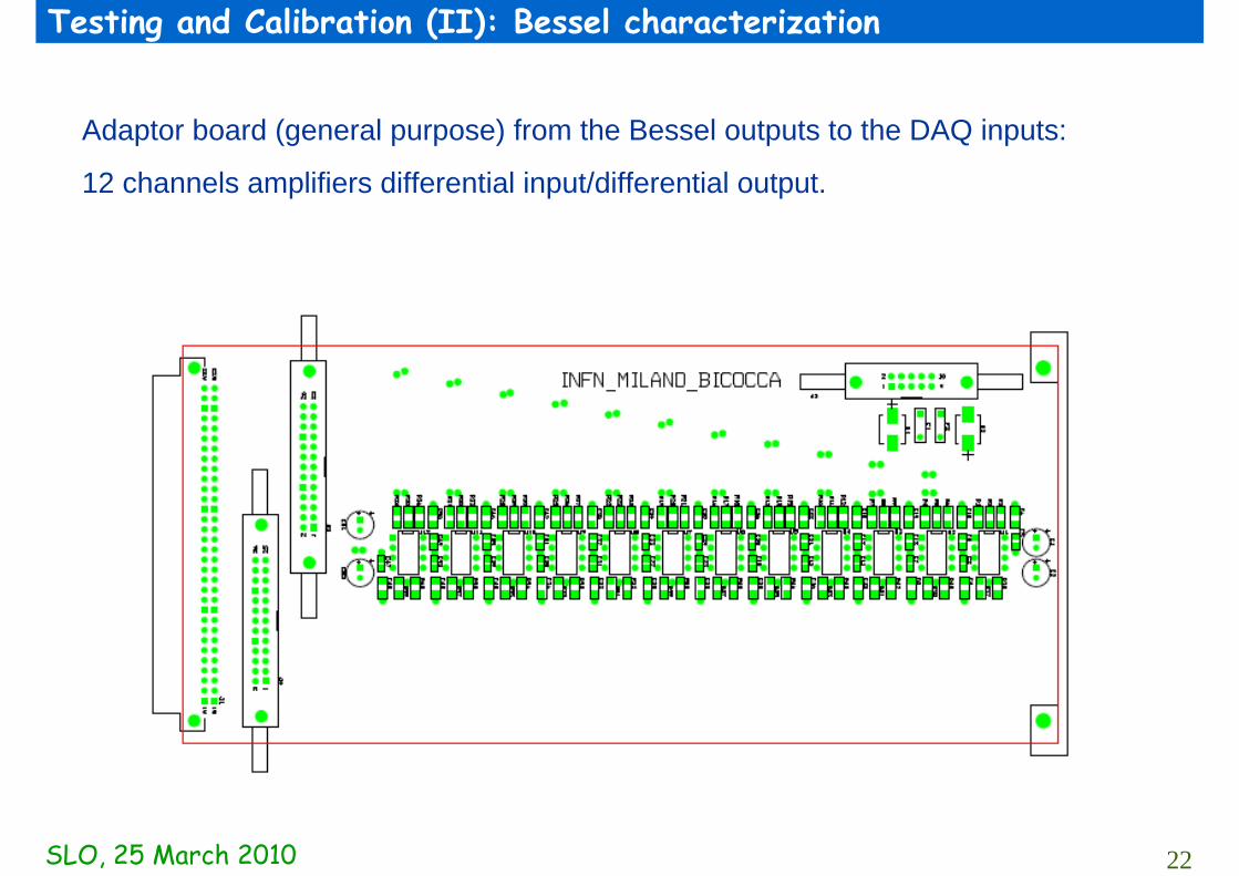
Adaptor board (general purpose) from the Bessel outputs to the DAQ inputs:
12 channels amplifiers differential input/differential output.

23SLO, 25 March 2010
Testing and Calibration (III): Bessel characterization
Adaptor board (general purpose) from the Bessel outputs to the DAQ inputs:
24 channels input/output,

24SLO, 25 March 2010
Testing and Calibration (IV): Bessel characterization
Single adaptor for Bessel Input/output board.

25SLO, 25 March 2010
Testing and Calibration (V): Bessel characterization
Input signal for testing a Bessel board

26SLO, 25 March 2010
Testing and Calibration (VI): Preamplifier
Testing Board for a single channel preamplifier.
Preamplifier

27SLO, 25 March 2010
Conclusions
The electronic system design is progressing.
The final production is on the way for the preamplifiers and the anti aliasing filter.
CUORE0 PEN tapes will be available within the next week;
Kapton boards are waiting for the production.