infrared process heating for industrial application
TRANSCRIPT

First Edition

Copyright © 2005 by the IRED Division of the Industrial
Heating Equipment Association, P.O. Box 54172, Cincinnati,
OH 45254-0172.
All rights reserved. The cover and text of this publication, or any part thereof, may not be reproduced or transmitted in any form or by an means, electronic or mechanical, in-cluding photocopying, recording, storage in an information retrieval system, or otherwise, without the prior written permission of the IRED Division of the Industrial Heating Equipment Association.
1

I n f r a r e d P r o c e s s H e a t i n g H a n d b o o k
Ta b l e o f C o n t e n t s
Introduction
5 Disclaimer
What is Infrared?
6 What is Infrared?
7 How is Infrared Energy Produced?
8 Characteristics of Infrared Energy
Equipment Sources of Infrared
10 Electric
11 Natural Gas and Propane
11 Gas Catalytic Infrared
12 How Does Infrared Compare to Convection?
12 Infrared Process Control
12 Controlling Electric Infrared
13 Controlling Gas Infrared
14 Zone Temperature Control
2
Table of Contents

Infrared Process Heating Applications
17 Application submitted by TVA
18 Application submitted by ITW BGK
19 Application submitted by Catalytic Industrial Systems
20 Application submitted by Fostoria Industries
21 Application submitted by Catalytic Industrial Systems
22 Application submitted by ITW BGK
23 Application submitted by ITW BGK
24 Application submitted by Catalytic Industrial Systems
25 Application submitted by Alabama Power Co. TAC West and Fostoria Industries
26 Application submitted by Fostoria Industries
27 Application submitted by Catalytic Industrial Systems
28 Application submitted by ITW BGK
29 Application submitted by Process Thermal Dynamics
3

A C K N O W L E D G E M E N T S
The IRED Division of the Industrial Heating Equipment Association gratefully acknowl-edges the following individuals and companies for their contributions to this handbook.
EDITORALABAMA POWER CO.
David A. Boone
•
EDITORIAL CONTRIBUTORSCATALYTIC INDUSTRIAL SYSTEMS
Dale Holroyd
•
FOSTORIA INDUSTRIES Steve Fruth
•
GAS TECHNOLOGY INSTITUTESteve Sikirica
•
ITW BGKGary Metzger
•
PROCESS THERMAL DYNAMICS, INC.Bob Beattie
•
RADIANT ENERGY SYSTEMS, INC.Bob Narang
•
SOLAR PRODUCTS INC.Paul Ross
•
TVASara Madugula
4

I n t r o d u c t i o n
The membership of the Infrared Equipment Division (IRED) of the Industrial Heating and Equipment Association (IHEA) is proud to present this fi rst edition handbook as a quick introduction to the many applications of infrared heating in industrial processes today. Infra-red (IR) process heating was fi rst developed in the 1930s for curing the paint on automobile bodies. Since then, IR heating has been successfully applied to hundreds of different process heating applications, such as curing metal fi nishes and protective coatings; fusing thermo set and thermoplastic powder coatings; forming molded plastics; bonding adhesives and metals; drying papers, inks, and fabrics; and processing foods.
When you understand the infrared basics, you can comfortably discuss improvements in your process heating systems with the infrared equipment manufacturers and the utility companies that help promote their applications. This teamwork approach to process improvement will ensure a well designed application of infrared heating. The “Infrared Applications” section of this handbook has been designed so that you can look for processes similar to your needs.
A list of IRED members can be found on the IHEA website along with additional informa-tion about IHEA and IRED: www.IHEA.org. We invite your questions and inquiries. Thanks for taking time to review our handbook. We hope you will fi nd it informative and useful as you explore the world of infrared heating.
D i s c l a i m e r
Nothing contained in this handbook shall constitute an endorsement by IRED / IHEA of any informa-
tion, opinion, procedure, or product mentioned. IRED / IHEA disclaims any liability with respect to
use of such information, procedure, or product, or reliance thereon. IRED / IHEA is not establishing or
recommending an industry standard. Nothing in this book shall be construed as a recommendation
by IRED / IHEA.
This handbook can only be considered a general guide. The contributors and publisher have neither
liability nor can they be responsible to any person or entity for any misunderstanding, misuse or
misapplication that would cause loss or damage of any kind, including material or personal injury, or
alleged to be caused directly or indirectly by the information contained in this handbook.
5

WHAT IS INFRARED?Comparing infrared with other methods of heat transfer can help you understand the infrared heating method. All heat is transferred by one of three methods:
• Conduction heating is the transfer of heat by physical contact between a heat source and the object to be heated. • Convection heating is the transfer of heat using heated air as the transfer medium between the heat source and the object to be heated • Radiation heating is the transfer of heat using invisible electromagnetic waves of energy from a heat source to the object to be heated.
Infrared is one of several ways to accomplish radiation heating along with ultraviolet, mi-crowave, radio frequency, and induction. This handbook is only concerned with infrared heating and therefore we will use the terms radiant and infrared interchangeably.
One of the fi rst forms of heat transfer each of us encoun-ter is radiant. The sun beam that warms us is radiant heat. Radiant energy is not absorbed by air and does not actually become heat until an object absorbs it. While radiant energy does generally show up as heat, this is because it vibrates and rotates the atoms in the absorbing object, which results in a rise in the temperature of that object. However, radiant energy may also show up as a chemical change in the absorbing object (polymerization) or evaporation of water or solvents (drying).
What is Infrared?
6
What is Infrared?

HOW IS INFRARED ENERGY PRODUCED?Every object with a temperature above absolute zero emits infrared energy. This is because there exists in every object a measured amount of heat, so each object has the ability to radiate heat from itself. The object that radiates heat is called the emitting source (see fi gures on page 11), and the object to which it radiates heat, having a lesser amount of heat content, is called the target.
There are several physical laws that explain the properties of infrared radiation. The Stefan-Boltzman law of radiation states that as the temperature of a heat source is increased, the radiant output increases to the fourth power of its temperature. The conduction and convection components increase only in direct proportion with the temperature change. In other words, as the temperature of a heat source is increased, a much greater percentage of the total energy output is converted into radiant energy.
For the purpose of this handbook, we will address only those sources of infrared heat used in industrial heating applications. This generally means looking at emitting source temperatures in a range from 500 degrees Fahren-heit to 4,200 degrees Fahrenheit. (These temperatures are not to be confused with oven set point temperatures or
any other temperature requirements related to your prod-uct or process). As the emitting source temperature moves from 500 degrees to 4,200 degrees, the radiant output increases with a corresponding increase in peak wave-length. At each temperature point, there is a unique set of wavelength characteristics and peak wavelengths. An additional set of physical laws helps us to understand this relationship. By applying Planck’s Law and Wien’s Law, it is possible to calculate both the distribution of wavelength (spectral distribution) and the peak wavelengths of a given emitter, operating at a given temperature.
The Stefan-Boltzman law relates the total amount of radiation emitted by an object to its temperature:
E = σ T4
E = total amount of radiation emitted by an object per square meter
σ is the Stefan-Boltzman constant = 5.67 x 10⁻⁸ Watts m−2 K−4
T is the temperature of the object in K°
Shortwave
Mediumwave
Longwave
6,400˚F.76 μm
2,150˚F2 μm
10 3 μm
Gammarays
X-rays Ultraviolet rays Infrared Microwave Radio waves
1 pm10-6 μm
1 nm10-3 μm
1 μm 1 mm103 μm
1 m106 μm
1 km109 μm
The electromagnetic spectrum describes the various types of electromagnetic energy based on wavelength.
Figure 1. In general, discussions
on infrared wavelengths are
categorized as either short,
medium, and long. A more
precise description of these
wavelengths is in Microns,
a unit of measure that is
1000th of a millimeter.
850˚F4 μm
Visible light
7

CHARACTERISTICS OF INFRARED ENERGYInfrared heating is the transfer of thermal energy in the form of electromagnetic waves. It is related to visible light and other forms of electromagnetic energy shown in the electromagnetic spectrum (Figure 1, page 7). The infrared portion of this spectrum has been expanded to show that we can further divide infrared into long wave, medium wave and short wave.
By describing an infrared emitter as long wave, medium wave, or short wave, one can quickly determine the ap-proximate temperature range an emitter is operating, as well as an approximate wavelength range measured in microns. Since the temperature of a source determines the wavelength characteristics of that source, the peak wavelength of a given emitter can be controlled only by changing the temperature of the emitter. All emitters can be adjusted for wavelength simply by adjusting their temperatures. However, not all emitters are designed to attain the complete spectrum of long, medium, and short wavelength.
There are some heat processing applications that are rather forgiving and will work with long, medium, or short wavelength infrared. On the other hand there are applications where it’s important to choose an emitter so that its wavelength distribution and peak wavelength match the absorption, refl ection and transmission char-acteristics of the coating or substrate. In these processes, choosing the right wavelength can make a tremendous difference in the overall effi ciency and speed of the process, and may even determine whether or not the process works.
Spectral Characteristics of Infrared There are many factors that determine whether a sub-strate or coating has the ability to heat up when infrared energy is applied. First, understand that infrared energy
is absorbed, refl ected or transmitted. For an object to be heated by infrared, some portion of the infrared energy from the emitting source must be absorbed. Once the en-ergy is absorbed, the heat generated at the surface travels into the material by conduction.
The factors that describe the behavior of infrared are referred to as Spectral Characteristics. They explain to what degree infrared is refl ected or absorbed in differ-ent materials. For all heating applications, matching the infrared output with the absorption spectrum will produce a heating process that is effective as well as energy effi cient.
Approximate Emissivity of Metals
Materials Nominal Polished Oxidized
Aluminum 0.05 0.15
Brass 0.09 0.60
Cast Iron 0.21 0.70
Copper 0.02 0.60
Galvanized 0.02 0.60
Glass 0.94
Stainless Steel 0.17 0.85
Steel 0.11 0.75
Rubber 0.86-0.95
Wood 0.95
The relationship between refl ectivity and absorption is called emissivity. An emissivity scale with a numeric value from 0 to 1 has already been developed for all ma-terials. A perfect absorber of infrared will have an emis-sivity value of 1 and is called a black body absorber. On the other end of the scale, a perfect refl ector of infrared will have an emissivity value of 0. Although emissivity can vary with thickness, temperature, and wavelength, emis-
8
What is Infrared?
Infrared source
Transmitted
Refl ected
Absorbed
Figure 2
sivity is generally approximated with a constant value. You can fi nd this value for many common materials in emissivity tables found in many engineering handbooks. A short list of emissivity values for some of the more com-mon materials used in industrial processes is provided in the table on page 8.
Another consideration for infrared applications is color sensitivity, which describes the role color has in determin-ing the absorption and refl ectivity of infrared. This can be a concern with highly refl ective colors such as silver or chrome, and must be considered with some white and yel-low colors since they tend to discolor if overheated. Color
sensitivity is more pronounced with higher emitter tempera-tures. For this reason, shortwave emitters are the most color sensitive and long wavelength emitters are the least color sensitive. In many industrial processes, the color sensitivity with medium and long wavelength emitters produces such a small change in temperature that it is negligible.
Variations in absorption can even be different for the same color depending on whether the fi nish is gloss, satin, or fl at. When applying infrared heat, give consideration to color as well as surface characteristics of the material. For best results, a range of heater temperatures should be tested to obtain the best absorption characteristics on suspect colors.
9
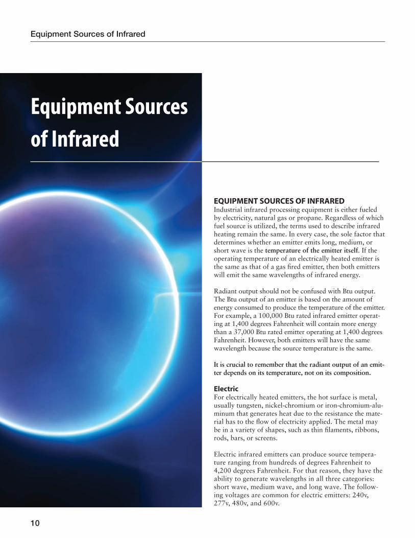
EQUIPMENT SOURCES OF INFRAREDIndustrial infrared processing equipment is either fueled by electricity, natural gas or propane. Regardless of which fuel source is utilized, the terms used to describe infrared heating remain the same. In every case, the sole factor that determines whether an emitter emits long, medium, or short wave is the temperature of the emitter itself. If the operating temperature of an electrically heated emitter is the same as that of a gas fi red emitter, then both emitters will emit the same wavelengths of infrared energy.
Radiant output should not be confused with Btu output. The Btu output of an emitter is based on the amount of energy consumed to produce the temperature of the emitter. For example, a 100,000 Btu rated infrared emitter operat-ing at 1,400 degrees Fahrenheit will contain more energy than a 37,000 Btu rated emitter operating at 1,400 degrees Fahrenheit. However, both emitters will have the same wavelength because the source temperature is the same.
It is crucial to remember that the radiant output of an emit-ter depends on its temperature, not on its composition.
ElectricFor electrically heated emitters, the hot surface is metal, usually tungsten, nickel-chromium or iron-chromium-alu-minum that generates heat due to the resistance the mate-rial has to the fl ow of electricity applied. The metal may be in a variety of shapes, such as thin fi laments, ribbons, rods, bars, or screens.
Electric infrared emitters can produce source tempera-ture ranging from hundreds of degrees Fahrenheit to 4,200 degrees Fahrenheit. For that reason, they have the ability to generate wavelengths in all three categories: short wave, medium wave, and long wave. The follow-ing voltages are common for electric emitters: 240v, 277v, 480v, and 600v.
Equipment Sources
of Infrared
10
Equipment Sources of Infrared

Natural Gas and PropaneThere are four major types of gas fueled infrared emitters: • metal fi ber matrix • ceramic fi ber matrix • ceramic tile • catalytic
Except for the catalytic type, heat is generated when pre-mixed gas and air are released through the porous mate-rial and burned at the surface. The burning gases heat the porous materials, which then emit infrared energy to the product. The surface temperature of the porous material, depending on the design of the emitter, operates in a range from 1,200 degrees Fahrenheit to as high as 2,000 degrees Fahrenheit. This temperature range puts these emitters in the medium wave category of infrared.
Metal fi ber matrix
Ceramic fi ber matrix
Ceramic tile
Catalytic
Gas fuel emitters
Gas CatalyticWith gas catalytic infrared emitters, unmixed fuel en-ters the back of the airtight heater pan and is dispersed through a catalyst pad which is preheated by a low watt-age electric element. Oxygen from the surrounding air diffuses through the catalyst pad from the front of the
heater. When the gas and oxygen meet in the presence of the heated catalyst, an oxidation-reduction reaction oc-curs, generating heat. Once the catalytic reaction begins, it is self-sustaining and the electric preheat element is de-energized. The surface temperature of these emitters oper-ates in a range from 450 degrees Fahrenheit to as high as 900 degrees Fahrenheit. This temperature range puts these emitters in the medium and long wave category of infra-red. Since the maximum surface temperature is below the auto-ignition temperature of the fuel, there is no fl ame.
11
Electrically heated emitter sources: samples
Robbon, surface mounted - resistance alloy Tungsten in a quartz envelope
Embedded - resistance alloy Metal sheath rod, nickel chrome spiral wire inside, protective metal sheathing outside.Figure 3
Figure 4
• Preheat catalyst by means of electric element
• Fuel enters emitter
• Fuel reacts with heated catalyst and atmospheric oxygen to produce heat energy
• Reaction becomes established
• Disconnect preheat elements
• Thermocouple or thermoswitch used to verify safe operation
Figure 5 Catalytic emitters

HOW DOES INFRARED COMPARE TO CONVECTION? Convection heating, particularly gas fi red convection, is the most common type of oven in the United States for industrial process heating. In these ovens, natural gas (methane), or liquefi ed petroleum gas (a mixture of butane and propane) is burned to provide heat. Most gas convection ovens are direct-fi red ovens, meaning the hot combustion gases come into direct contact with the product. In indirect fi red ovens, combustion takes place in a special chamber and heat exchangers are used to heat the air, which then comes into contact with the product.
In most applications, infrared heating offers numerous advantages over convection heating including:
• Higher rate of heat transfer • Higher effi ciency • Floor space savings • Lower maintenance • Faster response • Greater control accuracy • Ability to control temperature by zoning • Lower capital expense and install cost Infrared heating is more effi cient than convection because a higher percentage of the input energy goes into the product rather than being lost to the surround-ing air and lost up the fl ue. In addition, infrared ovens do not require long pre-production heat-up periods like convection ovens do. During these periods, a signifi cant amount of energy is consumed without any product being produced.
The higher rate of heat transfer is evident in the following heat transfer equations:
Q = watts
Convection Q = hA(Tp-Ta) h = coeffi cient of convection heat
transfer
A = area
Tp = temperature of the product
Infrared Q = σA(Tp4-Te4) Ta = temperature of the air
Te = temperature of the emitter
σ = Stefan-Boltzman constant
Convection heat transfer is a function of the tem-perature difference to the first power whereas infra-red heat transfer is proportional to the temperature difference to the fourth power. Because convection ovens have a lower heat transfer rate, the products
must be in the oven longer. The longer dwell time means more heat gets conducted into the part. When drying or curing coatings on the surface, the heat that gets conducted inside is wasted heat. Infrared’s high heat transfer rate raises the surface to the required temperature more quickly. This allows for shorter dwell times with less heat conducted into the part. This is another reason why infrared is more ef-ficient than convection.
When drying paint with a convection oven, it is some-times necessary to slow down the process to avoid blister-ing the coating. Since convection heating can only dry the coating from the outside in, rapid drying sometimes forms a dry skin at the surface of the paint. As the inside of the paint dries, the evaporating solvent blisters up through the dried skin eventually popping and leaving a crater with a pin hole.
With infrared heating, some of the energy heats the surface of the paint, and some energy is transmitted through the coating which helps to drive solvents out of the inside of the paint before the formation of a dry skin at the surface.
The shorter dwell times with infrared heating can trans-late to a much smaller oven, which can save valuable fl oor space, capital cost, and installation cost.
INFRARED PROCESS CONTROLControlling the heating process is one of the main ad-vantages of using infrared. Whether you are using long, medium, or short-wave infrared, gas or electric energy sources; utilizing infrared’s controllability to fi ne tune your process adds effi ciency, higher production rates and better quality control.
Controlling Electric InfraredThere are two basic methods used to control the emitter output, On/Off Control and Variable Control.
On/Off ControllersThe basic concept of On/Off Control is to turn power on and off to the emitter rapidly. The net effect will give an average emitter power output less than full output. By varying the percentage of time the power is on, the emitter can be adjusted from zero to full power. This method is typically used with long and medium wave emitters. Most long and medium wave emitters/elements have higher mass, which causes them to react more slowly to produce an even output. The use of On/Off Control is the least expensive and simplest method to control emitter output.
12
Equipment Sources of Infrared
On/Off controller
Emitter
Power source
Relay/contactor
Product
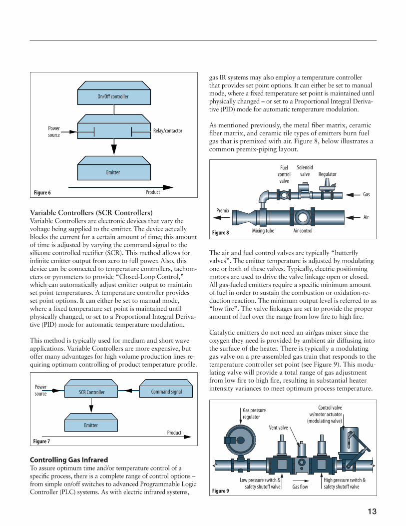
Variable Controllers (SCR Controllers)Variable Controllers are electronic devices that vary the voltage being supplied to the emitter. The device actually blocks the current for a certain amount of time; this amount of time is adjusted by varying the command signal to the silicone controlled rectifi er (SCR). This method allows for infi nite emitter output from zero to full power. Also, this device can be connected to temperature controllers, tachom-eters or pyrometers to provide “Closed-Loop Control,” which can automatically adjust emitter output to maintain set point temperatures. A temperature controller provides set point options. It can either be set to manual mode, where a fi xed temperature set point is maintained until physically changed, or set to a Proportional Integral Deriva-tive (PID) mode for automatic temperature modulation.
This method is typically used for medium and short wave applications. Variable Controllers are more expensive, but offer many advantages for high volume production lines re-quiring optimum controlling of product temperature profi le.
SCR Controller Command signal
Emitter
Product
Powersource
Controlling Gas InfraredTo assure optimum time and/or temperature control of a specifi c process, there is a complete range of control options – from simple on/off switches to advanced Programmable Logic Controller (PLC) systems. As with electric infrared systems,
gas IR systems may also employ a temperature controller that provides set point options. It can either be set to manual mode, where a fi xed temperature set point is maintained until physically changed – or set to a Proportional Integral Deriva-tive (PID) mode for automatic temperature modulation.
As mentioned previously, the metal fi ber matrix, ceramic fi ber matrix, and ceramic tile types of emitters burn fuel gas that is premixed with air. Figure 8, below illustrates a common premix-piping layout.
Mixing tube Air control
Solenoid valve Regulator
Premix
Gas
Air
Fuel control valve
The air and fuel control valves are typically “butterfl y valves”. The emitter temperature is adjusted by modulating one or both of these valves. Typically, electric positioning motors are used to drive the valve linkage open or closed. All gas-fueled emitters require a specifi c minimum amount of fuel in order to sustain the combustion or oxidation-re-duction reaction. The minimum output level is referred to as “low fi re”. The valve linkages are set to provide the proper amount of fuel over the range from low fi re to high fi re.
Catalytic emitters do not need an air/gas mixer since the oxygen they need is provided by ambient air diffusing into the surface of the heater. There is typically a modulating gas valve on a pre-assembled gas train that responds to the temperature controller set point (see Figure 9). This modu-lating valve will provide a total range of gas adjustment from low fi re to high fi re, resulting in substantial heater intensity variances to meet optimum process temperature.
Gas pressure regulator
Low pressure switch & safety shutoff valve
Vent valve
Control valve w/motor actuator
(modulating valve)
High pressure switch & safety shutoff valveGas fl ow
13
Figure 6
Figure 7
Figure 8
Figure 9

A further review and understanding of the many differ-ent types of gas controls available for industrial process control can be found in IHEA’s Combustion Technology Manual, Fifth Edition, 1994, published by the Combus-tion Division of IHEA.
Zone Temperature ControlIn addition to process speed and fl oor space requirements, another advantage of infrared over convection heat-ing is the ability to zone heat. A good example of how zoning can improve the effectiveness of a process is to look at water dry-off. In some drying applications, when the product fi rst enters the dryer, it can withstand high temperatures because of the amount of water in it. As the product moves through the oven or dryer and contains less moisture, it may be necessary to reduce the tempera-ture in subsequent zones to allow further drying without overheating and damaging the product.
In other applications, if a coating needs to be cured, sometimes a quick blast of high temperature is all that is needed to initiate the cross-linking process. In other cases, multiple zones of different heat intensity can be the best approach. The sample zoning confi gurations which fol-low (Figures 10, 11, 12 & 13) show the fl exibility of an infrared oven.
14
Equipment Sources of Infrared
Z1 Z2 Z3 Z4
Part fl ow
Longitudinal zoning technique(allows part temperature ramp profi ling)
Part Part
Figure 10
Z1
Z2
Z3
Part fl ow
Vertical zoning technique(allows diff erent height parts)
Part
Part
Figure 11

15
Parttravel
Combination zoning technique
Zone 1
Zone 1
Zone 1
Zone 1
Zone 1
Zone 2
Zone 2
Zone 2
Zone 2
Zone 2
Zone
2
Zone
2
Zone
2
Zone
2
Zone
2
Zone
7Zo
ne 6
Zone
5
Zone
4
Zone
3
IR cure oven
Profi le zoning technique(allows even part heating)
Z4 Z4
Z3 Z3
Z2 Z 2
Part fl ow
Z1
Figure 12
Zone 7Zone 6Zone 5Zone 4
Zone 3

Infrared Process Heating ApplicationsSince the 1930s, infrared heating has come a long way from its fi rst application of curing paint on automobiles. Today’s industrial processes are being fi ne-tuned with in-frared heating leading the way. This section will conclude our handbook by presenting examples of applications for some of the many industrial segments that infrared cur-rently serves. Because it would be impossible to include all the applications for infrared within each particular seg-ment, we have chosen to select some of the most common industrial segments.
If you see an application described in this section that fi ts your need or is close to addressing your process require-ments, we recommend that you contact an IRED member as the next step to evaluating the specifi cs of your ap-plication. We also suggest that you contact your utility supplier. Most utilities have energy experts available to assist you with virtually any energy related needs. A few utilities even have technology centers in partnership with the IRED membership. These centers are great places to see fi rsthand the benefi ts of infrared heating, as well as provide limited testing of your application. Final testing, engineering, and price quoting will be provided by the infrared equipment manufacturer.
We hope this handbook has been effective in presenting the benefi ts of infrared technologies. If you have any ques-tions or inquiries, please refer to our IRED membership list on the IHEA website: www.IHEA.org. Thank you for considering infrared technologies for your next process improvement project.
Infrared
Process Heating
Applications
16
Infrared Process Heating Applications

17
Background
The IRED member knew that the technology had im-proved over the past 10 years – and had the facts to back up their belief. Late 1998, when the facility was contem-plating ways to reduce fl oor space and increase produc-tion on its silk screening process, engineers didn’t seri-ously consider the electric infrared option - - until, that is, the IRED member showed them that a lot has changed over the last decade.
The Solution
With company offi cials receptive, a coating consultant from Electric Power Research Institute (EPRI) Center for Material Fabrication (CMF) was brought in for technical support. Several options were evaluated before deciding that an electric IR oven was the best device for preheating and curing the parts. Among the advantages are energy savings, quick cycle times, more precise controls, and safer and cleaner workplace environment.
The Results
After two months, with the new infrared process being used to cure silk screen inks and for pre-heating parts prior to applying decals on range control panels, he said the results are even better than expected. “In fact, we are so happy that we’re looking at installing another electric infrared oven at our facility.” Initial studies indicate that the new electric process will reduce the annual energy bill for the drying process by 40%. Just as important, it im-proves two other core business issues – it provides work-ers with a safer and cleaner workplace environment and is faster and more responsive to line conditions -- thus making the overall manufacturing process more effi cient. And it’s small -- a quality that matters at a plant in which space is at a premium.
Appliance manufacturer
Appliance parts requiring silk screened inks
About a decade ago, an appli-ance manufacturer evaluated an electric infrared (IR) system to use when curing silk screen inks and for pre-heating parts prior to applying the decals. The quality – compared to the gas infrared, that at that time was the indus-try standard – just didn’t stand up.
“This installation clearly shows that infrared can save money, and in the long run that helps everyone”.
Application Provided Courtesy of TVA
d rec
hatbill m-
h that infrared can save

Background
Conveyor Type ..................... OverheadLine Speed ............................ 45’ per minuteHot Air Oven Size ................ 20’ Wide x 100’ LongHot Air Oven Time .............. 30 minutes
Solution Process
• Increase production output• Process different colors without delays or contamination• Reduce time in hot air oven• Maintain high quality fi nish• No increase in labor cost• The IRED member proposed a process to utilize the
power and free conveyor along with a high inten-sity electric infrared booster oven.
• A 12’ section of opposing heaters in the existing oven vestibule was installed.
• The parts were conveyed in, as before, at 45 FPM. However, now the parts stopped for 12.4 seconds in the infrared booster section then continued on at 45 FPM.
• The total exposure time in front of the infrared was 28.4 seconds and the product temperature was raised to 250°F.
The booster section yielded the following results:
• The powder was melted and fl owed in the section
Case Goods
Steel
• Parts were hung from an overhead conveyor system and conveyed through the powder booth to the hot air oven.
• As the parts conveyed through the oven, the power and free conveyor would stack the parts for 30 minutes before they exited the oven.
• Parts of similar colors had to be run in batches to eliminate contamination.
• Increase in demand could not be met with the existing labor force.
of the oven without a lot of air fl ow. • Low air fl ow eliminated powder from becoming air-
borne in the oven and contaminating other parts of different colors.
• A 250°F rise in the product temperature reduced the hot air oven time from 30 minutes to 15 min-utes.
Benefi ts and Paybacks
Increased Production• Production rate was doubled (without an increase
in manpower or oven size). • Fewer delays, because colors no longer had to be
run in batches.Space Savings
• No added fl oor space since the infrared booster was able to be installed inside the existing hot air oven.(A gas oven with comparable capacity would be as big as the existing hot air oven, 20’ wide x 100’ long.)
Goals Were Met• All 6 goals set for this project were realized.• The customer has invested minimal time, money,
and man power to achieve these goals.• They are putting out high quality product in a more
effi cient method with no additional manpower required.
Application Provided Courtesy of ITW BGK
18
Infrared Process Heating Applications

19
Background
The products require more than 30 standard and custom-er requested powder colors. Production levels are 800,000 cylinders a year.
Solution Process
Three catalytic I.R. ovens. Dry-off, Pre-heat, and Cure oven systems.
Benefi ts/Payback
Doubled the line speed and throughput. Cure all products in house.Improved process control.
Application Provided Courtesy of Catalytic Industrial Systems
Eighty cylinder models used for scuba tanks, medical oxygen tanks, tanks for exotic gases, carbon dioxide tanks for soda and beer industry
Aluminum High Pressure Gas Cylinders
The company was outsourcing the coating operation.

20
Infrared Process Heating Applications
Background
The company has (4) production and coating lines. Their markets demanded that they expand beyond traditional electrocoat painting, and begin powder coating. They needed to add powder coating to at least one line that was originally designed for E-coating only.
Solution Process
Through the efforts and teamwork of the IR manufacturer and TVA, the local utility, a rather unique solution was determined. It had already been determined that electric infrared would be employed to speed up the powder coat-ing process, increase production, and bring the unit cost down. But trying to squeeze ovens in the lines was not the answer, again due to space considerations.
A novel approach to put an IR booster oven inside the convection oven was then considered and implemented. Locating IR components inside the oven is possible with specially designed refractory board and medium-wave quartz tube IR emitters, which are essentially impervious to the high temperature atmosphere inside the convec-tion oven. In addition, the refractory board reaches high enough temperatures that the board essentially becomes a secondary emitter and is basically self-cleaning.
Benefi ts and Paybacks
The IR equipment design addressed all anticipated fl oor space problems, and enabled this company to increase line speed and therefore increase production. Now they can quickly gel the powder just before the parts hit the high
This company manufactures and powder coats and/or e-coats suspension coil springs and trunk lid torsion bars for the global automotive markets.
Truck springs
Conventional thinking dictated a requirement for two separate ovens that would take up valuable fl oor space. “Adding new curing ovens would negatively impact other parts of the productionprocess, and consume the muchneeded production space”, according to their Plant Manager.
Truck Spring transparency goes here.
a
ine
TTTTTTTTTrTT uuuuuuuuuuuucucccccccccccuuuuuuuccccuuuuuuuccccccccccuuuuuuuuuuccccccccccccccuuuuuuuuuuccccccccccccccccuuuuuuuucucucuccccccucuccccccuuuuuuccuuuuuccccucuucucccucuccccccucccuuuuuuuuuuuuuuuuuuuuuuuuuuccuuuucucuuuccccuuuuuuucucccccuuuuuuuuuuucccccuuuuuuuuuucccckkkkkkkkk k k kkkkkkkkkkkkkkk kkkkkkkkkkkkkkkkkkkkkkkkkkkkkkkkkkkkkkkkkkkkkkkkkkkkkkkkkkkkkkkkkkkkkkkkkkkkkkkkkkkkkkkkkkkkkkkkkkkkkkkkkkkkkkkkkkkkkkkkkkkkkkkkkkkkkkkkkkkkkkkkkkkkkkkkkkkkkkkkkkkkkkkkkkkkkkkkkkkkkkkkkkkkkkkkkkkkkkkkkkkkkkkkkkkkkkkkkkkkkkkkkkk SSSSSSSSSSSSppSpppSppSppSSSSSSSSpSpSpSpSppSSSpSpSSpSppSppSSSpppSSSSpSpSpSpSpSpSpSpSppSpSSSpSpSppSpppppSSSSpSSSSpSpSpSSSSSSSSSSSSSSSSpSSSSSSSSSSSSSSSSSppSpppSSSSSSSSSSpSpSSSSSSpppSSSSSSSSSSSSppppppSSSSSSpSSSSSSSSpSSppSSSSSpSSSpSSSpSSpSSSSSppSSSSpppSSSpSSSSSSpSSSSSSSSSpSSSSSppppSSSppSSSSppSSSSSpSSSSpSSSSSSSpSSppSSSppSSppppppppppppppppppppppppppppppprrrrrriririrriririiirrrrrrrrrrriiirriirrrriririirrriiiirrrriirrriiiiiiiiriiiriiiiriiiiriiirrriirriirrrriiiiiiirriiirrrriiirrrriiirriiirrriiiiirriiirriiiiiiiiiirriiirriiiiiiriiingngnngngngngnngngngngngngngnggggggggnggngggggnngnngggngnggggggngngnngnggnggggnggngggngngggnnngngggnggggggnggggngggngnggngnggngggnngngnnngnngnngngg ttttt ttttt ttt tttttttt t ttttttttt tttttttttttttttttt ttt t ttttttttttttttttt t t rrrrrrrrrrrrrarrrrararararaararararararrrrrrrrrrrrrraraaarrrrrrrrrrrrraaarrrrrrrrrrraarrrrrrrrrrraraaaaarrrrraaarrrrrarrraaaraarrraarrrraraaarrarrrrraaarrrraraaaarrrrrrrraarrrrarrrarraraaaaarrrraaaannnnnnnnnnnnnnnnnnnnsnsnsnsnssnnnnnnnnnnnnnnssnsnnnnnsnsnnnnnsnnnnnnnnnnnnnnnnnnnnnnnnsnnnnnnnsnnnnnnnnnnnnnnnnnnsnssnnnnnnnnnnnnnnsnnnnnnnnnnnnnnnnnnnnnnnnnnnnnnnnnnnnnnnnnnnnnnnnnnnnnnnnnsnnnnnnnnnnnnsnnnnnnnnnsnsnsnnnnnnnnnnnnnnnnnnnnnnnnnnnnnnnnnnnnnnnnnnnnnnnnsnnnnnnnnnnnnnnnnnnnnnnsnnnnnnnnnn papapapapapapapappaaaaaaaapaaaaaaaaaaaaaaaaaaaaaaaaaaaaappaapaaaaaaapaaaaaaaapaaaapaaaaapppp rerrrererrrerrererrrrrrrrererrrrererererrrrrrrrrrrrrerreeerrrrrrrrrrereeerrrrrrrrrreererrrrrrerrerrrrrrrrrrrrereerrrerrrrreerrrrrrrerrrrrrrreerrrreerrrrrrrreeeerrerrrereereeerrerreeeerreeeeerreerencncncncncncncncncnccccccccccccccncnncncnccccccncncccnnncccccncccncccccccccccncccccccnnnncncncnnnnnncncncnnncncnccccnnnnnnnnnnncccnnnnnnnncccccccccccyyyyyyyyyyy y yyyyy y yyyyyyyyyyy y yyyyy y yy yyyyyyyyyy yyyyyyyyyyy yyyyyyyyyyyyyyyyyyyyyyyyyyyyyyyyyyyyyyyyyyyyyyyyy yyyyyyyyyyyyyyyyyyyyyyyyyy yyyyyyyyyyyyy yyyyyyyyyyyyyyyyyyyyyyyyyyyyyyyyyyyyyyyyyyyyyyyyyyyyyyyyyy gogogogogggggggogogogogoooogoooooooogogooggggogoooooooogogggggogoooooooggoooooogggooooogogggggoogogogogoggoooogogoooooooggooooooggooogggggoooooggooogggoogoogoogggooogggooooogggggggooggggogggggoggooogggggggggggggggggggggggggggggggggggggggggggggggggggggggg eeeeseseseseseeeeeeseseseeseeeeesseeeeeeeseeeeseeeeeeeeeeseeeeeeeeeeseeeeeeeeeeeeeeeeeeeeeeeseeeeeeeeeeeeeeeseeeeeeeeeeeeeeeesesseeeeeeeeeeeeeeeeeeseeeeeeeeeeeeeeeeeee hhhhh h h hhhhhhhhhhhhhhhhhhhhhhhhhhhhhhhhhhhhhhhh hhhhhhhhhhhhhhhhhhhhhhhhhhhhhhhhhhhhhhhhhhhhhhhhhhhhhhhhhhhhhhhhhhhhhhhhhhhhhhhhhhhhhhhhhhhhhhhhhhhhhhhhhhhhhhhhhhhhhhhhhhhhhhhhhhhhhhhhhhhhhhhhhhhhhhhhhhhh hhhhhhhh hhhhhhhhhhhhhhhhhhhhhhhhheeeeeeeeeeeeeeererrerrereeeeeeeeeeeeeeereeeeeeeeeeeeeeeeeeeeeeeeerreeeeeeeeeeeererereerreeerererererererrreereeeeeeeerererrrrrrrrrreeeeeeeereererrrrrrreeeeeeeeerrrreeeeeeeeeeeerrreeeeeeeeeeeerrrreeeeeeeeerreeeeeeeeerrreeeeeeeerereeeeeeeeeeeeeeerreeeerrereeeee eeeeeeee.e.eeeeeeeeeeeeeeeeeeeeeeeeeee.eee.e.e.ee.eeeeeeee.e.eeeeeeeeeeee.eeeeeeeeeeeeeee.eeeeeeeeeeeeeeeeeeeeeeeeeeeeeeeeeeeeeeeeeeeeeeeeeeeeeeeeeeee
turbulent area of the convection oven. They now also employ IR in their E-coating line for dewatering.
Lastly, the addition of the IR booster system changed the cure cycle substantially, since the direct heat was much quicker than convection, and the radiant heat was now being re-captured. The company can turn down the convection oven set points, and further save on energy consumption.
Application Provided Courtesy of Fostoria Industries

21
Background
Formally two convection ovens, each of them 80 ft long, were used for paint curing. The process required each engine to make fi ve conveyor trips through the ovens.
Solution Process
A new 40 foot long catalytic I.R. oven in place of an 80 foot long convection oven, reducing the cycle time by more than half, overall oven foot prints and conveyor length.
Benefi ts/Payback
Cut paint cycle time from 4 hours to 2 house. Reduced paint cure time from 50 minutes to 16 minutes. Replaced an 80 foot long convection oven with a 40 foot long I.R. oven, eliminating 240 feet of conveyor. Also creates a higher gloss on the fi nished product.
Application Provided Courtesy of Catalytic Industrial Systems
Wide range of boat engines fi nished in a black epoxy paint
Inboard and stern-drive marinepropulsion products
Company’s goal was to reduce-cycle times in order to better respond to the needs of their customers.

22
Infrared Process Heating Applications
Background
Conveyor Type ........................... OverheadLine Speed .................................. 5’ per minuteHanger Load .............................. 600 pounds (max)Cure Time .................................. 75 Minutes
• Gas convection curing with a 380’ oven.• After 75 minutes in a 475° oven the engine blocks
took a signifi cant amount of time to cool before packaging and shipping.
Solution Process
• 19’ short-wave infrared oven (only 5% of previous oven length)• 23 zones of control – allows for adjustments for
various part sizes• Instant oven response time – allows the power
setting to be reduced to idle during line stops and in between parts
Benefi ts and Paybacks
• Coating cured in 1/10 the time.• Infrared oven used only 5% of the fl oor space of
the gas convection oven (infrared oven took up 258 ft2 versus 7,200 ft2 for the gas oven)
• Increased production by 46%• 73% cost per part reduction
Application Provided Courtesy of ITW BGK
Engine Blocks
Steel
• Process time is too long and does not allow them to meet
production.• The entire engine block reached
475°, so a signifi cant cool time was required.
d
f

23
Background
Conveyor Type ........................... OverheadLine Speed .................................. 8’ per minuteHanger Spacing .......................... 4’ (varied)Hanger Load .............................. 100 pounds (max)Production Load ........................ 12,000 pounds/hour
(max)Partial Cure Time ....................... 90 seconds
• The 2-coat powder primer/topcoat system added signifi cant corrosion resistance and durability to their high-end sweepers.
• The problem was the 2-coat process needed to be added to an existing 1-coat layout. The customer approached the problem in stages.
• First, a powder primer booth was added to the line. • Parts needed to pass from the primer booth through
the convection oven all the way back to the topcoat booth and back through the convection oven.
Solution Process
• The decision to add an intermediate oven between primer and topcoats was obvious.
• The updated process begins when parts are manu-ally loaded onto hangers supported from the over-head conveyor.
• The hangers then travel through a pretreatment system, a dry-off oven and open-air cooling before entering the primer powder booth.
• Once primed, parts enter the infrared cure oven to partially cure the coating.
• Parts then immediately enter a cooling chamber and on through the topcoat powder booth.
• After the topcoat the conveyor serpentines through a long convection oven for fi nal full cure, through
another cooling chamber and back to the load/un-load area.
Benefi ts and Paybacks
• By adding the electric infrared, partial cure oven, the customer was able to transform an existing sin-gle pass, 1-coat powder fi nishing line into a single pass 2-coat system without conveyor modifi cations.
• As a result, the customer is able provide their cus-tomers with a premium corrosion resistant, pow-der-coated product with minimal conversion costs.
• The customer also realized signifi cant energy sav-ings, operating and maintenance costs.
• Most importantly they eliminated the requirement for a second shift.
Application Provided Courtesy of ITW BGK
Miscellaneous Weldments
Steel
• The two-pass requirement resulted in a bottleneck at the paint line and loss of overall production and an increase in manpower costs.
• Then the product mix began to include more 2-coat process parts.
Application Provided Courtesy of ITW BGK

24
Infrared Process Heating Applications
Background
Company changing to a propriety water-based coating and component parts fi nished prior to assembly.
Solution Process
Five catalytic I.R. ovens in place of convection and in line to sure each of the coats of fi nish required at a line speed of 20 FPM.
Benefi ts/Payback
The catalytic I.R. ovens reduced the fl oor space require-ments from 1,000 ft. total to 130 ft total, due to the cure time being reduced from 10 minutes to 1.3 minutes. Also the new ovens signifi cantly reduced fuel and air movement costs, plus greatly reduced conveyor requirements.
Application Provided Courtesy of Catalytic Industrial Systems
Components of wood offi ce furni-ture including conference tables, desks, credenzas, cabinets and wardrobes.
Wood offi ce furniture
Floor space requirements too large with convection ovens and boxed surface temperature higher than desired, resulting in extended cool down times with convection.
plus greatly reduced conveyor requi
i Provided Courtesy of Catalytic

25
Background
The customer needed to quickly drive off the extra mois-ture content that caused the veneer to be graded unaccept-able for processing downstream from the initial opera-tions. Previously, dielectric re-dryers had been employed, but the customer experienced several reliability and main-tenance issues associated with that type of equipment.
The Solution
Testing at the IRED member’s technical applications center, that included a simulated production oven, revealed that infrared could quickly drive off the extra moisture content in the veneer, to allow for a positive grading and subse-quent return of the veneer to the production line for fi nal processing. A new drying line incorporating short wave IR was installed independent of the primary drying line, and was dedicated to handle only the non-graded veneer.
The Results
This and a similar application at another facility have been operating for more than 4000 hours with no re-ported problems in the IR system’s ability to remove the necessary moisture from the veneer. Maintenance and reliability issues that plagued the previous system were not problems with the new IR system, once minor start-up issues were addressed. Having this separate IR line to handle the small percentage of veneer with the additional moisture levels, has served the customer very well.
Application provided courtesy of Alabama Power Co. TAC West and Fostoria Industries.
Manufacturer of wood veneer products
Wood veneer
Moisture content in a small percentage of veneer exiting the primary drying oven was not under the acceptable limits to be graded for use in downstream processing.
25
l

26
Infrared Process Heating Applications
Background
Lab testing performed at an IRED member’s test lab, enabled the customer to experiment with various con-fi gurations, watt densities, various IR heat sources and varying line speeds. The most fl exible system proved to be short wave electric infrared, using T-3 quartz lamps. They require little heat-up, respond to process changes extremely fast and can be de-energized instantly if needed. Cure times in as little as 30 seconds were also achieved. The oven confi guration, which basically employs IR on all four sides of the seal, allows the product to be completely surrounded by heat, or if need be, allows the IR to be focused on only the side or sides of the seal that have been coated, if the entire seal is not coated.
A “clam shell” oven design with pneumatic cylinders was also employed to allow the system to open-close around the product, and allow for ease of maintenance.
The rubber seals are used on doors, trunks, and hatch back/lift gates to provide an airtight and watertight seal. The manu-facturer applies a water based “low friction” coating to help reduce annoying rubbing noises and squeaks; and to prevent ice from accumulating that can cause the doors to freeze.
Extruded rubber seals for the automotive industry.
The manufacturers provide many sizes and types of seals, that require various heat and power densities, and various line speeds (normal ranges are 30 to 80 feet per minute), to adequately cure the coatings. They need a cur-ing system that brings instant on-off heating capabilities, cures the coating in as little as 30 seconds, is capable of completely surrounding the product, or be fl exible enough to cure just one coated side, if that is all that is required.
Lastly, the systems were designed with multiple heat zones utilizing SCR power controllers. The output of each zone is infi nitely variable from 0 to 100%, allowing the manufacturer to match the heat output to the require-ments of the curing process.
Benefi ts and Payback:
• Faster line speeds• Less maintenance with electric IR• Less product defects or damage. The product will
not overheat if the line stops, since the T-3 lamps are virtually instantaneous.
• Dependable results through precise control, and the ability to focus the heat at the exact areas to be cured
• Lower operating costs by heating just the areas that require a cure, and through the other benefi ts as outlined above.
Application Provided Courtesy of Fostoria Industries.
y
Lastly, the systems were designed with m lul iti lple e hheheatatili i SCR power controllers. The output of
100% allowing

27
Background
Primer black, yellow and orange paints are electrostatic air – sprayed on excavator parts. They are applied as two component urethane liquids.
Solution Process
Catalytic I.R. oven to reduce oven size, conveyor length, and cure time. Eliminated parking space for air drying assemblies and eliminated any building additions.
Benefi ts/Payback
Cure time from six to eight hours down to just 15 minutes. Cut required oven size by half
Application Provided Courtesy of Catalytic Industrial Systems
20-ton and 23-ton hydraulic excavators. Booms and arm weldments for 27, 33 and 45 ton excavators.
Construction machinery
A convection oven would take twice the fl oor space of an I.R . oven and the cost would be too much for convection, due to the need for more building structure.
ght hours down to just 15 minutes.Cut required oven size by half
Apppllpliicicatatioionn PProvidided Courtesy of CatalyticIndustrial Systems

28
Infrared Process Heating Applications
Background
Conveyor Type ........................... Chain-on-EdgeLine Speed .................................. 9 FPMCure Time .................................. 15 MinutesOven Size .................................. 60’ Long × 10’ WideOven Temperature ..................... 600°FOven Type .................................. Convection
Company used a 600°F convection oven to cure the non-stick coating onto the exterior portions of the cookware.
Solution Process
• To increase production without sacrifi cing quality of product
• Replaced convection oven with short-wave infrared oven
• Infrared oven reduced cure time to 1 minute and 20 seconds
Benefi ts and Paybacks
• Reduced heat into the workers environment• Increased production within the fi rst hour by 84
pieces• More consistent appearance (gloss, color, etc)• Reduced fl oor space from the 600 sq ft convection
oven to a 48 sq ft infrared oven
Application Provided Courtesy of ITW BGK
Aluminum Cookware
Non-Stick Coating
• The convection oven is operat-ing at maximum capacity
• Taking too long to cure parts• Signifi cant heat introduced into
workers environment
29
Background
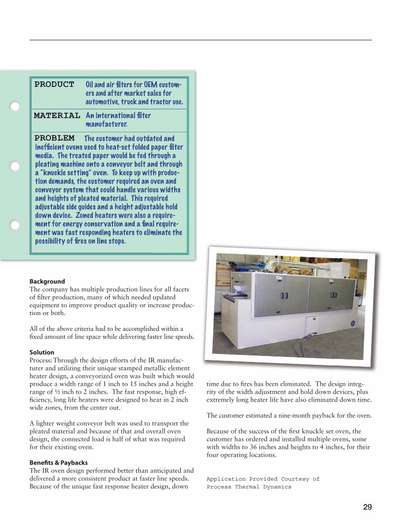
The company has multiple production lines for all facets of fi lter production, many of which needed updated equipment to improve product quality or increase produc-tion or both.
All of the above criteria had to be accomplished within a fi xed amount of line space while delivering faster line speeds.
Solution
Process: Through the design efforts of the IR manufac-turer and utilizing their unique stamped metallic element heater design, a conveyorized oven was built which would produce a width range of 1 inch to 15 inches and a height range of ½ inch to 2 inches. The fast response, high ef-fi ciency, long life heaters were designed to heat in 2 inch wide zones, from the center out.
A lighter weight conveyor belt was used to transport the pleated material and because of that and overall oven design, the connected load is half of what was required for their existing oven.
Benefi ts & Paybacks
The IR oven design performed better than anticipated and delivered a more consistent product at faster line speeds. Because of the unique fast response heater design, down
Oil and air fi lters for OEM custom-ers and after market sales for automotive, truck and tractor use.
An international fi lter manufacturer.
The customer had outdated and ineffi cient ovens used to heat-set folded paper fi lter media. The treated paper would be fed through a pleating machine onto a conveyor belt and through a “knuckle setting” oven. To keep up with produc-tion demands, the customer required an oven and conveyor system that could handle various widths and heights of pleated material. This required adjustable side guides and a height adjustable hold down device. Zoned heaters were also a require-ment for energy conservation and a fi nal require-ment was fast responding heaters to eliminate the possibility of fi res on line stops.
dtime due to fi res has been eliminated. The design integ-rity of the width adjustment and hold down devices, plus extremely long heater life have also eliminated down time.
The customer estimated a nine-month payback for the oven.
Because of the success of the fi rst knuckle set oven, the customer has ordered and installed multiple ovens, some with widths to 36 inches and heights to 4 inches, for their four operating locations.
Application Provided Courtesy of Process Thermal Dynamics

30
IRED members
Advanced Energywww.advancedenergy.org
Catalytic Industrial Systemswww.catalyticovens.com
Despatch Industries, L.P.www.despatch.com
Duke Energywww.dukeenergy.com
Electrotechnology Applications Center - Northhampton Community College www.etctr.com
Fostoria Industries, Inc.www.fostoriaindustries.com
Gas Technology Institutewww.gastechnology.org
ITW/BGK Finishing Systemswww.itwbgk.com
George Koch Sons, LLCwww.kochllc.com
Process Thermal Dynamics, Inc.www.pro-therm.com
Red-Ray Manufacturing Co., Inc.www.red-ray.com
TVAwww.tva.gov
Wisconsin Oven Corporationwww.wisinfrared.com

3131
$20.00 US