injector max ecinjector max ec- ---900900900a aaa · injector max ecinjector max ec- ---900900900a...
TRANSCRIPT

INJECTOR MAX ECINJECTOR MAX ECINJECTOR MAX ECINJECTOR MAX EC----900900900900AAAA
Operation Manual & Operation Manual & Operation Manual & Operation Manual & Adaptor KitAdaptor KitAdaptor KitAdaptor Kit
Fortron Automotive Treatments Pty LtdFortron Automotive Treatments Pty LtdFortron Automotive Treatments Pty LtdFortron Automotive Treatments Pty Ltd
14 14 14 14----18 Sangiorgio Court18 Sangiorgio Court18 Sangiorgio Court18 Sangiorgio Court, , , , Osborne ParkOsborne ParkOsborne ParkOsborne Park,,,, Perth Perth Perth Perth,,,, Western Australia 6017 Western Australia 6017 Western Australia 6017 Western Australia 6017
Ph Ph Ph Ph:::: (+61(+61(+61(+618) 92028) 92028) 92028) 9202 7800780078007800 Fax (+61 Fax (+61 Fax (+61 Fax (+618)8)8)8) 9202920292029202 7878787851515151 ---- www.fortron.com.auwww.fortron.com.auwww.fortron.com.auwww.fortron.com.au
Version Date: 1/2/12

CONTENTSCONTENTSCONTENTSCONTENTS
IntroductionIntroductionIntroductionIntroduction 1111
ECECECEC----900A900A900A900A / EC / EC / EC / EC----900D900D900D900D 2222
OOOOperating Instruperating Instruperating Instruperating Instructions Fuel Injection Cleanerctions Fuel Injection Cleanerctions Fuel Injection Cleanerctions Fuel Injection Cleaner ---- PetrolPetrolPetrolPetrol 3333----4444
OperatiOperatiOperatiOperatingngngng Instructions F Instructions F Instructions F Instructions Fueueueuel Injection Cleanerl Injection Cleanerl Injection Cleanerl Injection Cleaner ---- DieselDieselDieselDiesel 5555----6666
Operating Instructions Vacuum Intake CleanerOperating Instructions Vacuum Intake CleanerOperating Instructions Vacuum Intake CleanerOperating Instructions Vacuum Intake Cleaner 7777
OperatinOperatinOperatinOperatingggg Instructions Throttle Body / Instructions Throttle Body / Instructions Throttle Body / Instructions Throttle Body / InductionInductionInductionInduction Cleaner Cleaner Cleaner Cleaner 8888
Adaptor KitAdaptor KitAdaptor KitAdaptor Kit 9 9 9 9----13131313

INTRODUCTIONINTRODUCTIONINTRODUCTIONINTRODUCTION
It is a well known fact that almost all modern engines of today use a fuel
injection system to deliver fuel directly to engine combustion chamber; this
allows for improved engine efficiency which results in less pollutants and better
fuel economy for the customer.
Modern engine tuning today is typically done automatically by the engine
management system which manages correct fuel / air ratios of fuel through the
fuel injection system. This enables the engine to operate as efficiently as
possible.
Due to the location of the fuel injectors on today’s modern engines, fuel
injectors get heat soak when the engine is turned off. The engine heat causes
fuel evaporation at the fuel injectors, resulting in gum, varnish and tar deposits
accumulating around and on the fuel injector nozzles. This together with
carbon accumulation from poor quality carbon based fuels will cause
imperfections in the fuel injector spray pattern and in some cases cause fuel
injector blockage.
Regular services of the fuel rail and fuel injector system will remove these
unwanted deposits and ensure engine efficiency and reliability.
Fortron Injector Max will remove all deposits from the fuel rail through to fuel
injectors without damaging the engine, fuel pump and fuel lines.
The Fortron Injector Max fluid is a crude oil based solvent designed specifically
to remove unwanted deposits from the fuel injection system for both Petrol and
Diesel engines. Fortron recommend a fuel injection system clean every
20,000km/ 1 year depending on driving conditions.

- 1 -
ECECECEC----900A900A900A900A
AdaptAdaptAdaptAdaptoooor r r r KKKKit it it it ---- EC EC EC EC----900D900D900D900D
- 2 -
↓↓↓↓ Vactek Filler Injector Max ↓↓↓↓ Induction
Premix Filler
Pressure Gauge
Pressure
Release Valve Vacuum Gauge
Pressure Regulating
Valve
Fuel Outlet
Hose (RED)
Premix Supply
Valve EC-900A Vacteck
Vacuum Hose
(CLEAR)
Fuel Return
Hose (BLUE)
Vactek Fluid
Release Valve

OPOPOPOPERATING INSTRUCTIONS FOR ECERATING INSTRUCTIONS FOR ECERATING INSTRUCTIONS FOR ECERATING INSTRUCTIONS FOR EC----900A900A900A900A
FUEL INJECTOR CLEANING MACHINEFUEL INJECTOR CLEANING MACHINEFUEL INJECTOR CLEANING MACHINEFUEL INJECTOR CLEANING MACHINE
PETROLPETROLPETROLPETROL
SAFETYSAFETYSAFETYSAFETY - Ensure that the vehicle is in a safe environment, i.e. level surface, well
ventilated, handbrake on and transmission in neutral or park. (It is always prudent
when working with fuel, to have a fire extinguisher handy.)
1. Reset all switches on the machine to the ‘OFF’ position.
2. Remove the fuel filler cap from the vehicle to balance the pressure.
3. Remove the fuel pump fuse on the vehicle.
4. Determine the fuel delivery and return hose to the fuel tank on the
vehicle. If there is no fuse, loop these hoses together.
5. Add Injector Max premix to the pressure container on the right hand side
of the machine. (Make sure that the cap is screwed down tight after
adding the mixture).
6. Connect the Red fuel supply tube from the machine to the intake side of
the fuel rail.
7. Connect the Blue return hose to the fuel hose return tank on the vehicle.
(Note: if there is no return hose, as on some vehicles, leave the blue hose
disconnected).
8. Fit the air hose to the EC-900A machine and turn on.
9. With the central air pressure relief valve in the OFF position, adjust the
pressure valve to the manufacturer’s required pressure. (This is
important so as to avoid damage to the fuel rail pressure regulator on the
vehicle)
……Continued Page 4
- 3 -

10. Open the fuel supply valve. Make sure that there are no fuel leaks.
If fuel leaks are observed do not continue with service until fuel If fuel leaks are observed do not continue with service until fuel If fuel leaks are observed do not continue with service until fuel If fuel leaks are observed do not continue with service until fuel leaks are rectified.leaks are rectified.leaks are rectified.leaks are rectified.
11. Start the engine and run at idle until all fluid has been consumed.
12. Turn off the main air line and then turn the central air pressure relief
valve to ON (this will release the pressure in the machine). Then turn off
the fuel supply valve to OFF position.
12. Disconnect the machine from the vehicle.
13. Replace the fuel hoses on the vehicle, replace fuse if applicable, replace
the filter cap, start the engine; check for leaks and road test the vehicle.
- 4 -
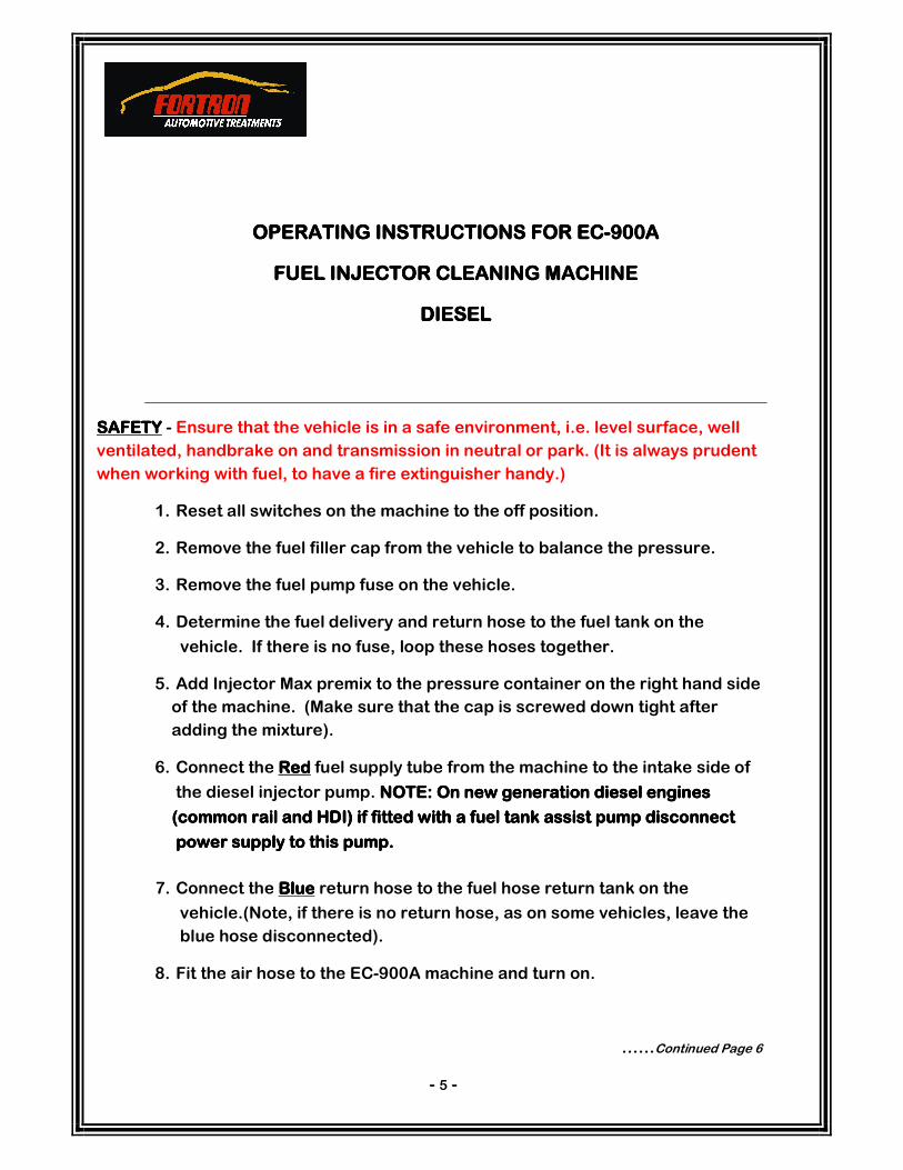
OPERATING INSTRUCTIONS FOR ECOPERATING INSTRUCTIONS FOR ECOPERATING INSTRUCTIONS FOR ECOPERATING INSTRUCTIONS FOR EC----900A900A900A900A
FUEL INJECTOR CLEANING MACHINEFUEL INJECTOR CLEANING MACHINEFUEL INJECTOR CLEANING MACHINEFUEL INJECTOR CLEANING MACHINE
DIESELDIESELDIESELDIESEL
SAFETYSAFETYSAFETYSAFETY - Ensure that the vehicle is in a safe environment, i.e. level surface, well
ventilated, handbrake on and transmission in neutral or park. (It is always prudent
when working with fuel, to have a fire extinguisher handy.)
1. Reset all switches on the machine to the off position.
2. Remove the fuel filler cap from the vehicle to balance the pressure.
3. Remove the fuel pump fuse on the vehicle.
4. Determine the fuel delivery and return hose to the fuel tank on the
vehicle. If there is no fuse, loop these hoses together.
5. Add Injector Max premix to the pressure container on the right hand side
of the machine. (Make sure that the cap is screwed down tight after
adding the mixture).
6. Connect the RedRedRedRed fuel supply tube from the machine to the intake side of
the diesel injector pump. NOTE: On new generation diesel engines NOTE: On new generation diesel engines NOTE: On new generation diesel engines NOTE: On new generation diesel engines
(common rail and HDI) if fitted with a fuel tank assist pump disconnect (common rail and HDI) if fitted with a fuel tank assist pump disconnect (common rail and HDI) if fitted with a fuel tank assist pump disconnect (common rail and HDI) if fitted with a fuel tank assist pump disconnect
popopopower supply tower supply tower supply tower supply to this this this this pump. pump. pump. pump.
7. Connect the BlueBlueBlueBlue return hose to the fuel hose return tank on the
vehicle.(Note, if there is no return hose, as on some vehicles, leave the
blue hose disconnected).
8. Fit the air hose to the EC-900A machine and turn on.
……Continued Page 6
- 5 -

9. With the central air pressure relief valve in the off position, adjust the
pressure valve to the manufacturers required pressure (This is
important so as to avoid damage to the fuel rail pressure regulator).
Open the fuel supply valve. Make sure that there are no fuel leaks.
If fuel leaks are observed do not continue with service until fuel leaks If fuel leaks are observed do not continue with service until fuel leaks If fuel leaks are observed do not continue with service until fuel leaks If fuel leaks are observed do not continue with service until fuel leaks are rectified.are rectified.are rectified.are rectified.
10. Start the engine and run at idle until all fluid has been consumed.
11. Turn off the main air line and then turn the central air pressure relief
valve to ON (this will release the pressure in the machine). Then turn off
the fuel supply valve to OFF position.
12. Disconnect the machine from the vehicle.
13. Replace fuel hoses on the vehicle, replace fuse if applicable, replace the
filler cap, start the engine; check for leaks and road test the vehicle.
- 6 -

OPERATING INSTRUCTIONS FOR ECOPERATING INSTRUCTIONS FOR ECOPERATING INSTRUCTIONS FOR ECOPERATING INSTRUCTIONS FOR EC----900A900A900A900A
VACUUM INTAKE CLEANINGVACUUM INTAKE CLEANINGVACUUM INTAKE CLEANINGVACUUM INTAKE CLEANING
SAFETY SAFETY SAFETY SAFETY - Ensure that the vehicle is in a safe environment, i.e. level surface, well
ventilated, handbrake on and transmission in neutral or park. (It is always prudent
when working with fuel, to have a fire extinguisher handy.)
1. Empty one bottle of Fortron Vactek detergent into the container on the
left hand side of the EC-900A machine.
2. Connect the vacuum tube on the EC-900A machine to a vacuum port on
the inlet manifold of the vehicle. (The more central the better). Start the
engine.
3. Open the vacuum valve on the machine to allow the detergent to flow to
the inlet manifold. (Flow is regulated through the vacuum valve)
4. Start the engine and run at moderate idle with a slow consistent flow of
Vactek detergent being drawn into engine.
5. Monitor vacuum gauge operation.
6. Occasionally increase engine rpm to allow the engine to run smoothly.
7. When the specified amount of Vactek detergent has been used, stop the
engine. Remove the delivery tube, and refit the vacuum line to the intake
manifold and road test the vehicle.
- 7 -

OPERATING INSTRUCTIONS FOR ECOPERATING INSTRUCTIONS FOR ECOPERATING INSTRUCTIONS FOR ECOPERATING INSTRUCTIONS FOR EC----900A900A900A900A
THROTTLE BODY/INDUCTION CLEANINGTHROTTLE BODY/INDUCTION CLEANINGTHROTTLE BODY/INDUCTION CLEANINGTHROTTLE BODY/INDUCTION CLEANING
SAFETYSAFETYSAFETYSAFETY ---- Ensure that the vehicle is in a safe environment, i.e. level surface, well
ventilated, handbrake on and transmission in neutral or park. (It is always prudent
when working with fuel, to have a fire extinguisher handy.)
1. Reset all switches on machine to ‘OFF’ position.
2. Empty one can of Fortron Induction Cleaning Fluid into the container on the
right side of the machine, marked PREMIX. Be sure to secure filler cap.
3. Fit S-Tool Throttle Body Adaptor to the Red discharge hose.
4. Connect air pressure hose to the EC-900A machine.
5. Set the required air pressure by adjusting the Air Pressure Regulator.
Usually 20-30 psi is adequate to obtain effective spray cleaning pattern
through S-Tool Adaptor.
6. Remove engine air induction tube at the throttle body to enable the S-tool to
be fitted.
7. Start vehicle and then open fuel supply valve on the EC-900A Monitor
and adjust engine rpm to assist in obtaining maximum cleaning efficiency.
NOTENOTENOTENOTE: On vehicles without Fly by Wire electronic throttle control, the
cleaning process may be done by manually opening the throttle plate
without the vehicle running.
8. When all fluid has been consumed and the throttle body area is clean,
turn off air line and turn central pressure relief valve to on, so that air
pressure is released.
9. Stop the engine, remove S-Tool Adaptor and refit air induction tube, then
road test vehicle.
- 8 -
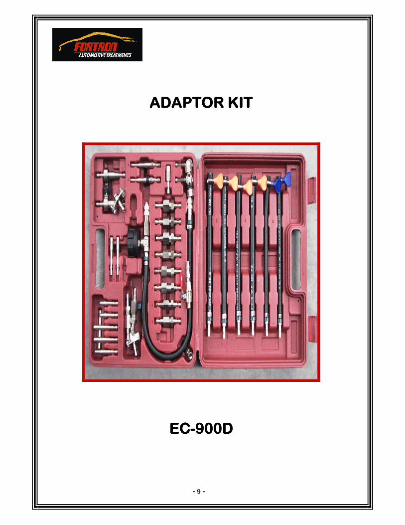
ADAPTOR KITADAPTOR KITADAPTOR KITADAPTOR KIT
ECECECEC----900D900D900D900D
- 9 -

- 10 -
ADAPTOR ADAPTOR ADAPTOR ADAPTOR KIT KIT KIT KIT –––– ECECECEC----900D900D900D900D

- 11 -

- 12 -

P/N 32
- 13 -