aaa-2000-3752 helicon plasma injector and … · helicon plasma injector and ion cyclotron...
TRANSCRIPT
Source of AcquisitionNASA Johnson Space Center AAA-2000-3752
HELICON PLASMA INJECTOR AND ION CYCLOTRON ACCELERATIONDEVELOPMENT IN THE VASIMR EXPERIMENT
Jared P. Squire", Franklin R. Chang Dia4 Verlin T. Jacobson $ , and Greg E. McCaskill§Advanced Space Propulsion Laboratory, JSC / NASA, Houston, TX
Roger D. BengtsonThe University of Texas at Austin, Austin, TX
Richard H. Goulding"Oak Ridge Nationdl Laboratory, Oak Ridge, TN
ABSTRACT
In the Variable Specific Impulse MagnetoplasmaRocket (VASIMR) radio frequency (rf) waves bothproduce the plasma and then accelerate the ions. Theplasma production is done by action of helicon waves.These waves are circular polarized waves in thedirection of the electron gyromotion. The ionacceleration is performed by ion cyclotron resonantfrequency (ICRF) acceleration. The Advanced SpacePropulsion Laboratory (ASPL) is actively developingefficient helicon plasma production and ICRFacceleration. The VASIMR experimental device at theASPL is called VX-10. It is configured to demonstratethe plasma production and acceleration at the IOkWlevel to support a space flight demonstration design.The VX-10 consists of three electromagnets integratedinto a vacuum chamber that produce magnetic fields upto 0.5 Tesla. Magnetic field shaping is achieved byindependent magnet current control and placement ofthe magnets. We have generated both helium andhydrogen high density (>1018 M-3 ) discharges with thehelicon source. ICRF experiments are underway. Thispaper describes the VX-10 device, presents recentresults and discusses future plans.
"Senior Research Scientist, Muniz Engineering, Inc.'ASPL Director, NASA Astronaut.# Research Staff, Muniz Engineering, Inc.$ Electrical Engineer Staff, Muniz Engineering, Inc.9 Research Professor, Fusion Research Center.Research Staff, Fusion Energy Division.
Copyright © 2000 by the American Institute ofAeronautics and Astronautics, Inc. No copyright isasserted in the United States under Title 17, U.S. Code.The U.S. Government has a royalty-free license to exerciseall rights under the copyright claimed herein forGovernment Purposes. All other rights are reserved by thecopyright owner.
INTRODUCTION
High power density plasma propulsion would vastlyimprove human exploration of our solar system. Thefusion energy research community has long known thatmagnetized plasma systems enable high energy densitydischarges, and that the magnetic field insulates thematerial wall from the hot plasma. Radio frequency (rf)waves have proven to be efficient at plasma productionin helicon' devices, where a right-hand circularlypolarized wave is launched into the plasma. Also infusion research, ion cyclotron resonant heating (ICRH)2has been very successful at producing energetic ionswithout having electrodes or grids in contact with theintense plasma. The same concept of rf production andheating of magnetized plasmas can be used for highperformance propulsion.
Efficient helicon plasma production and injection into astrong magnetic field is crucial for the performance ofthe Variable Specific Impulse Magnetoplasma Rocket(VASIMR) concept.3, 3 The subsequent ICRFacceleration of the ions via rf driven waves is necessaryto produce significant thrust. The experiment in theAdvanced Space Propulsion Laboratory (ASPL) at theNASA Johnson Space Center is presently focused onresearch in these two areas. The experimental device inthe ASPL is called VX-10. It is configured to operatein the 10 kW power range to support the design of anearly space flight demonstration of the VASIMRconcept. 5 This paper reports on the status of thehelicon plasma source development and ICRFacceleration research.
THE VX-10 EXPERIMENT
The VX-10 experiment is quickly evolving to aconfiguration that demonstrates the plasma productionand ion acceleration components of the VASIMRconcept. The VX-10 will soon operate at a total power
1American Institute of Aeronautics and Astronautics
https://ntrs.nasa.gov/search.jsp?R=20100029999 2018-09-06T00:51:31+00:00Z

Quartz tube Helicon o I (a)5 cm dia, antenna °1Mgas
feed
sur I5 m "3,or ichambe
box0
directional HRF sourc r Ioncoupler 1 kW g gauge
Helicon Quartz tube o (b)antenna 5 cm dia a
gas \ \ Ma
feed
res
45 m^3
ensor ^ ^ chamber
Match v .. .'_t" '̀` W J I
box a ICRF0
° ant. Qdirectional RF sourc array Ion
coupler 3 kW0
gauge
FIG. 1. Experiment configurations. (a) Helium heliconstudy configuration. (b) Low field helicon configurationwith magnetic choke for hydrogen experiments.
level of 10 kW and targets a specific impulse of 5,000to 10,000 seconds. Figure 1 shows two mainconfigurations in the recent experimental evolution.The primary focus of the work so far has been heliconplasma production with helium and hydrogen. Theearlier configuration (Fig. la) was designed to producean almost uniform magnetic field for just helicon study.The later configuration incorporates what we call a lowfield helicon section and magnetic choke. Thisconfiguration also has shifted the helicon antennalocation and moved the gas injection plate to a muchlower magnetic field location. The ICRF antenna isinstalled near the ma g netic choke. Figure 2 shows theVX-10 in operation.
In the present configuration (Fig. lb), neutral gas(hydrogen or helium in the present data) is injected atless than or about 1 m g/s into an axisymmetricmagnetic field that is shaped in strength alon g the axis.
The injected neutral gas is contained in a quartz tube (5cm in diameter) until it is ionized by an rf drivenhelicon wave in a magnetic field on the order of 0.1Tesla. The plasma then flows near the sound speed,about 10' m/s, into a hi gh magnetic field, about 0.2Testa for hydrogen, region where ICRF accelerationtakes place. The accelerated ions (--100 eV) move outin an expanding magnetic nozzle where perpendicularvelocity is converted to axial velocity.
FIG. 2. The VX-10 device running.
The magnetic field in the experiment is produced usingthree independently driven liquid nitrogen cooledcopper coil electromagnets capable of a maximum fieldof 0.3 Tesla for 10 minutes. A one Tesla capability forshort pulses, 30 seconds, is being implemented. Lightweight high temperature superconducting magnets arebeing developed to replace the low cost copper
magnets. 6 The VX-10 will soon start evolving to asuperconducting magnet system.
A precision mass flow controller (MFC) measures andregulates gas flow into the system. The MFC range is10 — 1000 standard cubic centimeters per minute(sccm). This corresponds to maximum mass flow ofabout 1.5 mg/second for hydrogen. The MFC also has100 ms time response for gas pulsing experiments. Abaratron measures the pressure in the gas inlet. Amagnetically shielded ion gauge measures the neutralpressure in the vacuum chamber at the plasma exhaustregion. The plasma exhausts into a 5 m 3 vacuumchamber, which is pumped at 5000 liters/second.Components for a 50,000 liter/second pump upgradehave been acquired and installation is being planned.
In the helicon section, a water-cooled half-turn helicalantenna is driven at 7 — 50 MHz with up to 3 kW of
2American Institute of Aeronautics and Astronautics
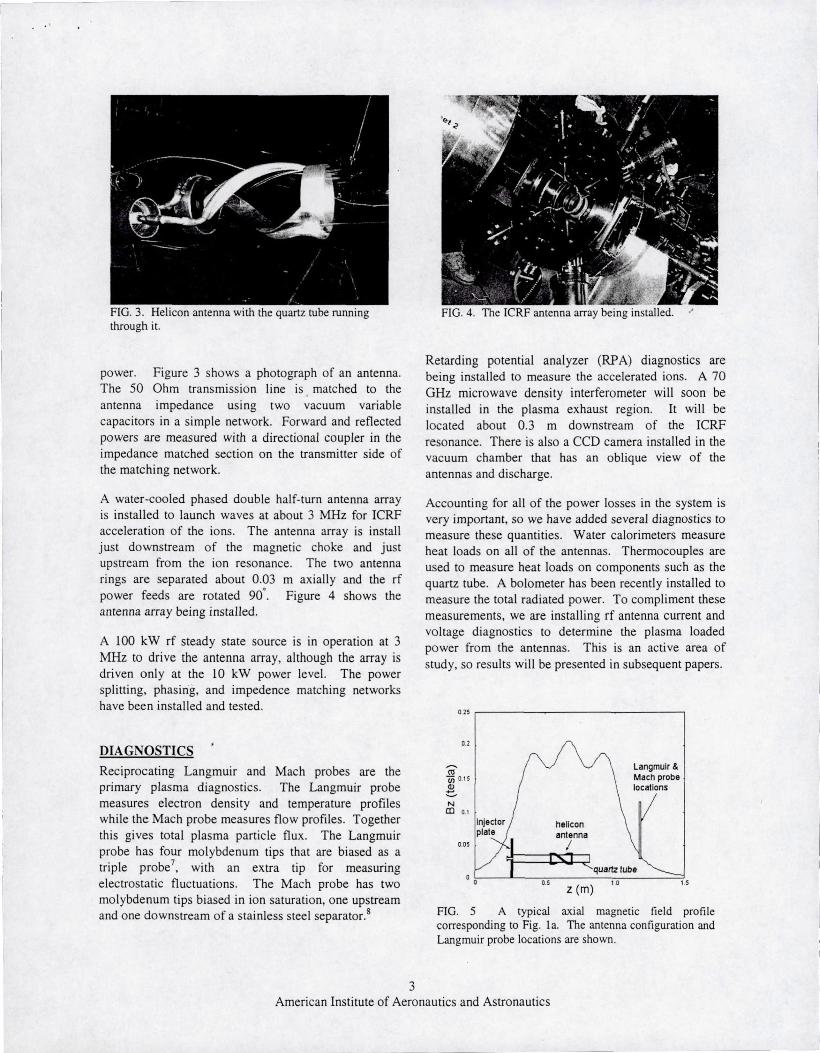
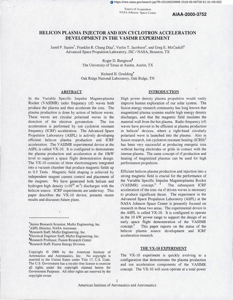
FIG. 3. Helicon antenna with the quartz tube runningthrough it.
FIG. 4. The ICRF antenna array being installed.
power. Figure 3 shows a photograph of an antenna.The 50 Ohm transmission line is matched to theantenna impedance using two vacuum variablecapacitors in a simple network. Forward and reflectedpowers are measured with a directional coupler in theimpedance matched section on the transmitter side ofthe matching network.
A water-cooled phased double half-turn antenna arrayis installed to launch waves at about 3 MHz for ICRFacceleration of the ions. The antenna array is installjust downstream of the magnetic choke and justupstream from the ion resonance. The two antennarings are separated about 0.03 m axially and the rfpower feeds are rotated 90 *. Figure 4 shows theantenna array being installed.
A 100 kW rf steady state source is in operation at 3MHz to drive the antenna array, although the array isdriven only at the 10 kW power level. The powersplitting, phasing, and impedence matching networkshave been installed and tested.
DIAGNOSTICS
Reciprocating Langmuir and Mach probes are theprimary plasma diagnostics. The Langmuir probemeasures electron density and temperature profileswhile the Mach probe measures flow profiles. Togetherthis gives total plasma particle flux. The Langmuirprobe has four molybdenum tips that are biased as atriple probe', with an extra tip for measuringelectrostatic fluctuations. The Mach probe has twomolybdenum tips biased in ion saturation, one upstreamand one downstream of a stainless steel separator.8
Retarding potential analyzer (RPA) diagnostics arebeing installed to measure the accelerated ions. A 70GHz microwave density interferometer will soon beinstalled in the plasma exhaust region. It will belocated about 0.3 m downstream of the ICRFresonance. There is also a CCD camera installed in thevacuum chamber that has an oblique view of theantennas and discharge.
Accounting for all of the power losses in the system isvery important, so we have added several diagnostics tomeasure these quantities. Water calorimeters measureheat loads on all of the antennas. Thermocouples areused to measure heat loads on components such as thequartz tube. A bolometer has been recently installed tomeasure the total radiated power. To compliment thesemeasurements, we are installing rf antenna current andvoltage diagnostics to determine the plasma loadedpower from the antennas. This is an active area ofstudy, so results will be presented in subsequent papers.
025
0.2
Langmuir &Mach probe .locations
heliconantennaf '
quartz tubez
(m),0
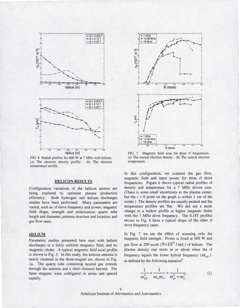
FIG. 5 A typical axial magnetic field profilecorresponding to Fig. la. The antenna configuration andLangmuir probe locations are shown.
^a^ Ot5N
Nm 0t
0.05
3American Institute of Aeronautics and Astronautics
EC
NC
c
r
radius (m)
aB=0055T—B=0.18T
B=0.25T
Na^
r
-7MHze +13.56 MHz
-- 19 MHz
B (tesla)
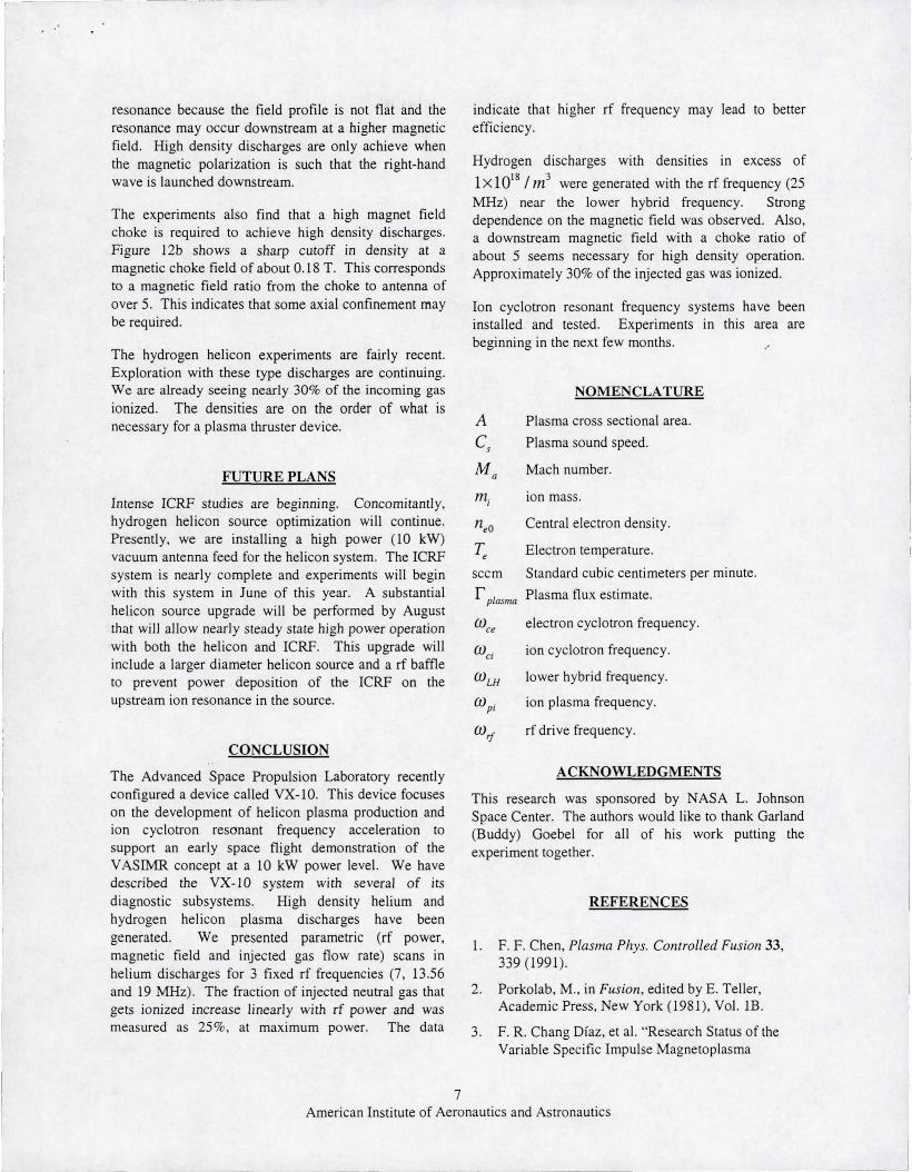
radius [m]FIG. 6 Radial profiles for 600 W at 7 MHz with helium.(a) The electron density profile. (b) The electrontemperature profile.
HELICON RESULTS
Configuration variations of the helicon section arebeing explored to optimize plasma productionefficiency. Both hydrogen and helium dischargesstudies have been performed. Many parameters arevaried, such as: rf drive frequency and power; magneticfield shape, strength and polarization; quartz tubelength and diameter; Antenna structure and location; andgas flow rates.
HELIUM
Parametric studies presented here start with heliumdischarges in a fairly uniform magnetic field, and nomagnetic choke. A typical magnetic field axial profileis shown in Fig. 5. In this study, the helicon antenna isnearly centered in the three-magnet set, shown in Fig.Ia. The quartz tube containing neutral gas extendsthrou-h the antenna and a short distance beyond. Thethree magnets were confi gured in series and spacedequally.
FIG. 7. Magnetic field scan for three rf frequencies.(a) The central electron density. (b) The central electrontemperature.
In this configuration, we scanned the gas flow,magnetic field and input power for three rf drivefrequencies. Figure 6 shows typical radial profiles ofdensity and temperature for a 7 MHz driven case.(There is some small uncertainty to the plasma center,but the r = 0 point on the graph is within 1 cm of thecenter.) The density profiles are usually peaked and thetemperature profiles are flat. We did see a modechange to a hollow profile at higher magnetic fieldswith the 7 MHz drive frequency. The 0.18T profilesshown in Fig. 6 have a typical shape of the other rfdrive frequency cases.
In Fig. 7 we see the effect of scanning only themagnetic field strength. Power is fixed at 600 W and
gas flow at 200 sccm (9X10' 9 /Sec) of helium. Theplasma density rise starts at or about when the rf
frequency equals the lower hybrid frequency (0) LH ).
as defined by the following equation9
1 1 1
(0 (Oce^ci dpi + (ci
4American Institute of Aeronautics and Astronautics

,m ^ m m sm 6m ,gym
Prf [Watts]
°oE+half-width m
0 os
om
° of
om
s plasma particle Flux
°° .m U mJ tle 6m a° ,m ®° 900 i® „mPrf [Watts]
FIG. 8 Power scan at 13.56 MHz with 200 sccm ofhelium. (a) Central electron density and temperature.(b) Profile half-width and plasma flux estimate.
C 5
Oi.
IC°^ 5
F^ a Teoa o° s io is m n
Helium flow [10 19 x particle/sec]
om^ half-width m
ooa
cca ^s
oo,s
s plasma particleflux
°o s aHelium flow [10 19 x particle/sec]
FIG. 9 Injected gas flow scan for 1000 W at 13.56 MHz.(a) Central electron density and temperature. (b) Profilehalf-width and plasma flux estimate.
e
I
6
6O
C
E ^
N
E
L
mL
UN
Q EO Lm
U
Q Lx0c
UN
mO
v.UQx
c
The density peaks when wrf = 0.25coLH . The density
quickly falls off at higher ma gnetic fields. The electrontemperature, shown in Fig. 7b, rises quickly at the firstdensity rise, but then changes very little. The higherfrequency generates a slightly higher temperature.These results indicate that higher frequency operationcould lead to better plasma production performance.
I
Figure 8 shows the result of scanning the rf power for a13.56 MHz drive frequency with 200 sccm mass flowof helium. Below about 150 W, a high density helicondischarge can not be generated, but a very low densitydischarge is still seen. After the helicon dischar ge iswell started, above 300 W, the density rises almostlinearly with the applied power. The electrontemperature rises very slowly and stays about 7 eV.The profile shape almost stays constant as shown by thehalf-width plotted in Fig. 8b.
Also shown in Fia. 8b is an estimate of the total plasmaT
flux ( 1 p,..mn ) in the exhaust. This is estimated by
1 plasma "-- 11eo ' A - C s , (2)
where n eo is the central electron density, A is the
effective cross sectional area of the plasma colume asdetermined by the Langmuir probe profile, and
CS = Je / nt, is the plasma sound speed. This
formula assumes a sonic flow speed of the plasma,since the Mach probe typically measures a sonic
(Ma 0 1) flow speed. The plasma flux estimatealmost rises proportional to the applied power. At themaximum power, about 25% of the injected neutral gasgets ionized.
Figure 9 plots the effect of scanning the injected gasrate for fixed power at 1000 W. Below flow rates of
5American Institute of Aeronautics and Astronautics

FIG. 11. Hydrogen plasma exhaust with the Langmuirprobe inserted.
about 5x 10' 9 / SeC , hi gh density discharges could not
be generated. Above flow rates of about
20 x 10 19 / sec , the background vacuum chamberneutral pressure is very hi gh and may be effecting thedownstream measurements. Between the flow ratelimits, the plasma density and flux estimate generallyrise with input gas flow rate. The electron temperaturetrends downward and the profiles tend to broaden.About 25% of the injected gas becomes ionized,independent of the input flow rate.
Z.5
UN 7NNU
WIS.a
i
5
Sm 0025 0m 00a 0a 0.5 00
B at antenna (tesla)
Langmuirbolomete probe
helicon quartz 'injector antenna tube iplate }^
Maii \ / pro
Langmuir \probe
05 10 15
Z (m)
FIG. 10. Two typical magnetic field axial profilescorresponding to Fig. lb. The helicon antenna
configuration and Langmuir probe locations are shown.
0e
o^
UNN06
NU
r 05a
00.
Vo3X
`4
dX01
0015 0a 03
B at antenna (tesla)FIG. 12. Plasma flux estimate measure duringmagnetic field scans for hydrogen discharges with 2000W at 25 MHz. (a) The field under the helicon antennascan with the choke field fixed. (b) The choke fieldscanned with the field at the antenna fixed.
0 2:
015
Nm
m o1
0.05
uvnunCPN
Hydrogen helicon discharge studies performed at theOak Ridge National Laboratory 10 discovered that highdensity plasma production is only achieved near thelower hybrid frequency in the VX-10 type ofconfiguration. We reconfigured the VX-10 device, asfigure lb shows, in preparation of hydrogenexperiments with a lower hybrid resonance in thehelicon section. Figure 10 shows the typical magneticprofile. The plasma exhaust with the Langmuir probeinserted is shown in Fig. 11.
The VX-10 also sees the close connection to the lowerhybrid frequency. We see a very strong density
dependence on the magnetic field when O)rf = O)L.H as
Fig. 12a shows. Here we carefully scanned themagnetic field in the low field region near the antenna.The hydrogen flow was 70 sccm and the input rf powerwas 2 kW at 25 MHz. We see a strong peak in thedensity at a specific field strength. This field issomewhat lower than that required for lower hybrid
6American Institute of Aeronautics and Astronautics
resonance because the field profile is not flat and theresonance may occur downstream at a higher magneticfield. High density discharges are only achieve whenthe magnetic polarization is such that the right-handwave is launched downstream.
The experiments also find that a high magnet fieldchoke is required to achieve high density discharges.Figure 12b shows a sharp cutoff in density at amagnetic choke field of about 0.18 T. This correspondsto a magnetic field ratio from the choke to antenna ofover 5. This indicates that some axial confinement maybe required.
The hydrogen helicon experiments are fairly recent.Exploration with these type discharges are continuing.We are already seeing nearly 30% of the incoming gasionized. The densities are on the order of what isnecessary for a plasma thruster device.
FUTURE PLANS
Intense ICRF studies are beginning. Concomitantly,hydrogen helicon source optimization will continue.Presently, we are installing a high power (10 kW)vacuum antenna feed for the helicon system. The ICRFsystem is nearly complete and experiments will beginwith this system in June of this year. A substantialhelicon source upgrade will be performed by Augustthat will allow nearly steady state high power operationwith both the helicon and ICRF. This upgrade willinclude a larger diameter helicon source and a rf baffleto prevent power deposition of the ICRF on theupstream ion resonance in the source.
CONCLUSION
The Advanced Space Propulsion Laboratory recentlyconfigured a device called VX-10. This device focuseson the development of helicon plasma production andion cyclotron resonant frequency acceleration tosupport an early space flight demonstration of theVASIMR concept at a 10 kW power level. We havedescribed the VX-10 system with several of itsdiagnostic subsystems. Hi gh density helium andhydrogen helicon plasma discharges have beengenerated. We presented parametric (rf power,magnetic field and injected gas flow rate) scans inhelium discharges for 3 fixed rf frequencies (7, 13.56and 19 MHz). The fraction of injected neutral gas thatgets ionized increase linearly with rf power and wasmeasured as 25%, at maximum power. The data
indicate that higher rf frequency may lead to betterefficiency.
Hydrogen discharges with densities in excess of
1x10 18 /m 3 were generated with the rf frequency (25MHz) near the lower hybrid frequency. Strongdependence on the magnetic field was observed. Also,a downstream magnetic field with a choke ratio ofabout 5 seems necessary for high density operation.Approximately 30% of the injected gas was ionized.
Ion cyclotron resonant frequency systems have beeninstalled and tested. Experiments in this area arebeginning in the next few months.
NOMENCLATURE
A Plasma cross sectional area.
CS Plasma sound speed.
M Mach number.n
mi ion mass.
/1e0 Central electron density.
T Electron temperature.
sccm Standard cubic centimeters per minute.
rPtnsma Plasma flux estimate.
aO , electron cyclotron frequency.
()a ion cyclotron frequency.
Q)Ly lower hybrid frequency.
O)Pi ion plasma frequency.
wrf rf drive frequency.
ACKNOWLEDGMENTS
This research was sponsored by NASA L. JohnsonSpace Center. The authors would like to thank Garland(Buddy) Goebel for all of his work putting theexperiment together.
REFERENCES
1. F. F. Chen, Plasma Plrys. Controlled Fusion 33,339 (1991).
2. Porkolab, M., in Fusion, edited by E. Teller,Academic Press, New York (1981), Vol. 113.
3. F. R. Chan g Diaz, et al. "Research Status of theVariable Specific Impulse Magnetoplasma
7American Institute of Aeronautics and Astronautics
Rocket", Transactions of Fusion Technology, 35,87 (1999).
4. Chang Diaz, this conference.
5. Petro, A. this conference.
6. Schwenterly, S.W., et al, "HTS Magnets forAdvanced Magnetoplasma Space PropulsionApplications," to be published in Advances inCryogenic Engineering, 45 (2000).
7. Chen, S. and Sekiguchi, T., J. Appl. Phys., 36, no.8, p. 2363.
8. Hutchinson, I.H., Phys. Rev. A, 37, no. 11, p. 4358.
9. Stix, T. Waves in Plasmas (American Institute ofPhysics, New York, 1992).
10. Goulding, R.H., et al., Bulletin of the AmericanPhysical Society, Program of the 41 s' AnnualMeeting of the Division of Plasma Physics, 44,(1999) p99.
i
-J
8American Institute of Aeronautics and Astronautics