innovative localizer antenna beats the...
TRANSCRIPT
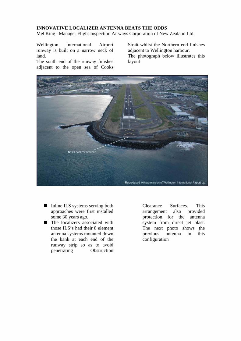
INNOVATIVE LOCALIZER ANTENNA BEATS THE ODDS Mel King –Manager Flight Inspection Airways Corporation of New Zealand Ltd. Wellington International Airport runway is built on a narrow neck of land. The south end of the runway finishes adjacent to the open sea of Cooks
Strait whilst the Northern end finishes adjacent to Wellington harbour. The photograph below illustrates this layout
Inline ILS systems serving both approaches were first installed some 30 years ago. The localizers associated with
those ILS’s had their 8 element antenna systems mounted down the bank at each end of the runway strip so as to avoid penetrating Obstruction
Clearance Surfaces. This arrangement also provided protection for the antenna system from direct jet blast. The next photo shows the previous antenna in this configuration
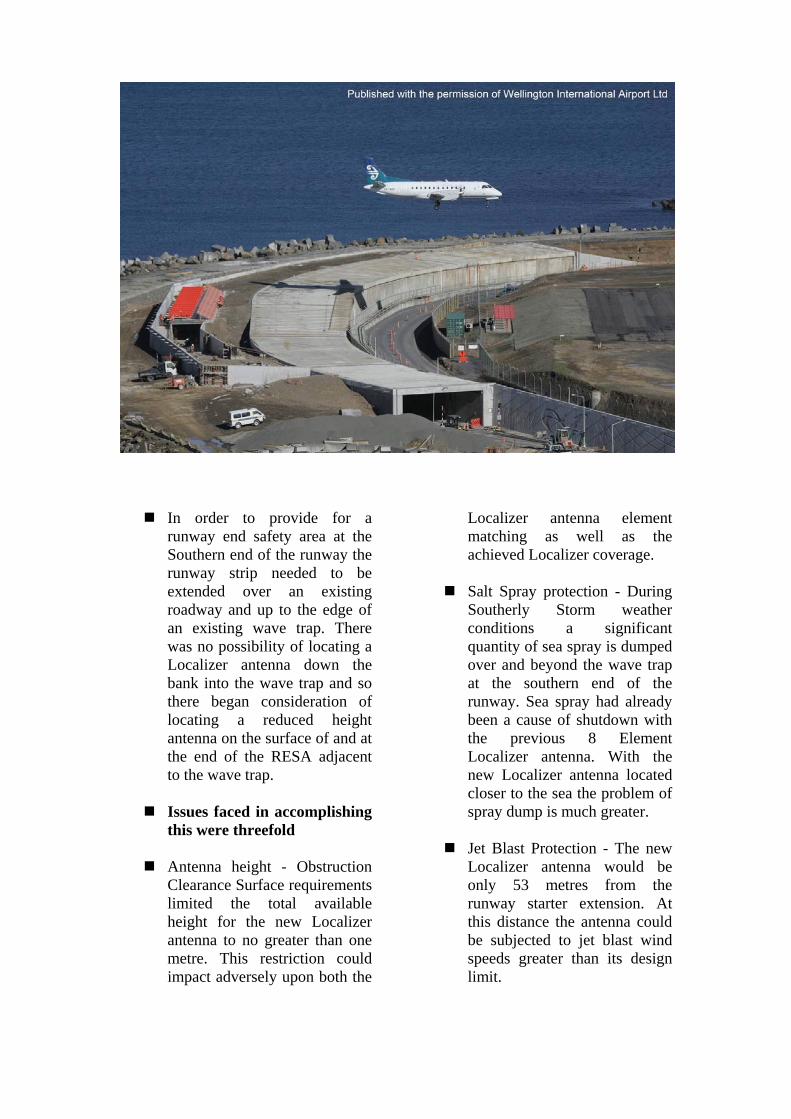
In order to provide for a runway end safety area at the Southern end of the runway the runway strip needed to be extended over an existing roadway and up to the edge of an existing wave trap. There was no possibility of locating a Localizer antenna down the bank into the wave trap and so there began consideration of locating a reduced height antenna on the surface of and at the end of the RESA adjacent to the wave trap.
Issues faced in accomplishing
this were threefold
Antenna height - Obstruction Clearance Surface requirements limited the total available height for the new Localizer antenna to no greater than one metre. This restriction could impact adversely upon both the
Localizer antenna element matching as well as the achieved Localizer coverage.
Salt Spray protection - During
Southerly Storm weather conditions a significant quantity of sea spray is dumped over and beyond the wave trap at the southern end of the runway. Sea spray had already been a cause of shutdown with the previous 8 Element Localizer antenna. With the new Localizer antenna located closer to the sea the problem of spray dump is much greater.
Jet Blast Protection - The new
Localizer antenna would be only 53 metres from the runway starter extension. At this distance the antenna could be subjected to jet blast wind speeds greater than its design limit.

Antenna Height Issue To check the effect upon the
antenna element matching a single antenna element was mounted on a variable height support and the Input feed
VSWR measured at various heights. The following plot shows that
matching was not going to be a problem and was best at around 600mm height
Localizer coverage issue-The difference in signal strength in the user airspace between a ‘down the bank’ mounted 8 element antenna and a normal height [1.8m] surface mounted 8 element antenna is approximately 10dB. A graph
of the relative signal level versus height for a surface mounted array is displayed in the next plot. This shows the 10dB reduction occurs around 0.55m height. This suggested a suitable minimum height to mount the antenna array.
Thales{Wilcox} Localizer LPD Input SWR versus height
1.07
1.08
1.09
1.1
1.11
1.12
1.13
1.14
500 550 600 650 700 750 800 850 900 950Graph 1 -Height above ground surface - mm
Inpu
t SW
R
Graph 2 -Signal level relative to 1.8m [Normal] antenna height
-12.00
-10.00
-8.00
-6.00
-4.00
-2.00
0.00
2.00
0.5 0.6 0.7 0.8 0.9 1 1.1 1.2 1.3 1.4 1.5 1.6 1.7 1.8 1.9 2
Height above ground - metres
Gai
n re
lativ
e to
1.8
m h
eigh
t

Whilst a low mounted antenna system appeared to potentially match the coverage of the previous ‘down the bank’ system it was decided to add some margin by using a 14 element array together with placing the equipment room
underground immediately below the antenna array in order to minimize cable loss. Thus we were confident that we would achieve a coverage not less than that previously obtained with the down the bank antenna.
Protection from Sea Spray Dump

To investigate protection
measures we firstly undertook tests upon a single antenna element to determine what
parts were most sensitive to the presence of salt water. The test setup is illustrated
below.
Signal Generator
Directional Coupler
Vector Voltmeter
Oscilloscope Adaptor
Laptop PC
B A
Phase Amplitude
Antenna under test
Far field sampling Antenna

Test equipment Location

Sea Spray Watering Set up

Salt Spray test- No Protection
-800
-600
-400
-200
0
200
400
600
800
1000
0 10 20 30 40 50 60
Elapsed time - seconds
Am
plitu
de -
mV
Phase Amplitude 20 per. Mov. Avg. (Phase) 20 per. Mov. Avg. (Amplitude)
1.9dB
Normal level
19Degrees
Spray duration
Sea Spray Simulation Sea Spray Dump Test Results – No Protection
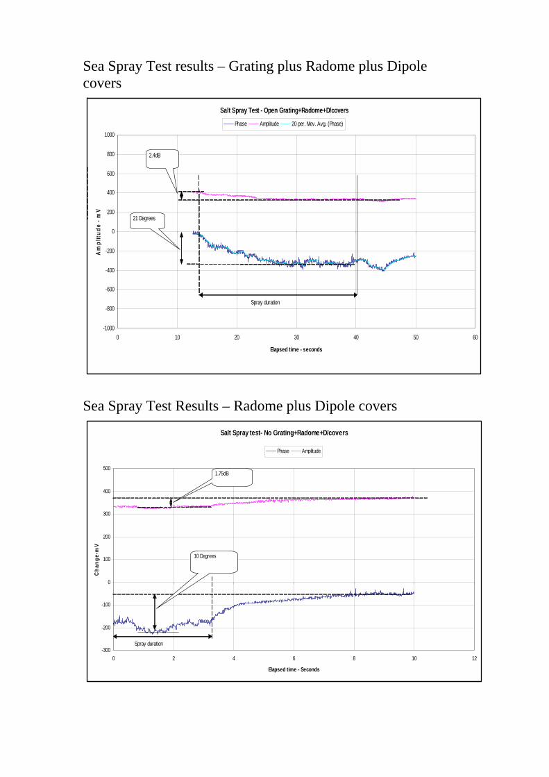
Sea Spray Test results – Grating plus Radome plus Dipole covers Sea Spray Test Results – Radome plus Dipole covers
Salt Spray Test - Open Grating+Radome+D/covers
-1000
-800
-600
-400
-200
0
200
400
600
800
1000
0 10 20 30 40 50 60
Elapsed time - seconds
Am
plitu
de -
mV
Phase Amplitude 20 per. Mov. Avg. (Phase)
21 Degrees
2.4dB
Spray duration
Salt Spray test- No Grating+Radome+D/covers
-300
-200
-100
0
100
200
300
400
500
0 2 4 6 8 10 12
Elapsed time - Seconds
Cha
nge-
mV
Phase Amplitude
10 Degrees
1.75dB
Spray duration

Sea Spray Test results – Radome plus Dipole Lips Final Protection Configuration
Salt Spray Test- Radome+D/Lips
-1000
-800
-600
-400
-200
0
200
400
600
800
1000
0 10 20 30 40 50 60
Elapsed time -Seconds
Ampl
itude
- m
V
Phase Amplitude 20 per. Mov. Avg. (Phase) 20 per. Mov. Avg. (Amplitude)
11 Degrees
0.5dB
Spray duration
This final protection
configuration reduced the signal amplitude disturbance to an insignificant amount.
The signal phase disturbance
remained essentially the same as with the full dipole covers.
Overall this final protection
scheme provided around a 2:1 improvement for signal phase disturbance over having no protection.
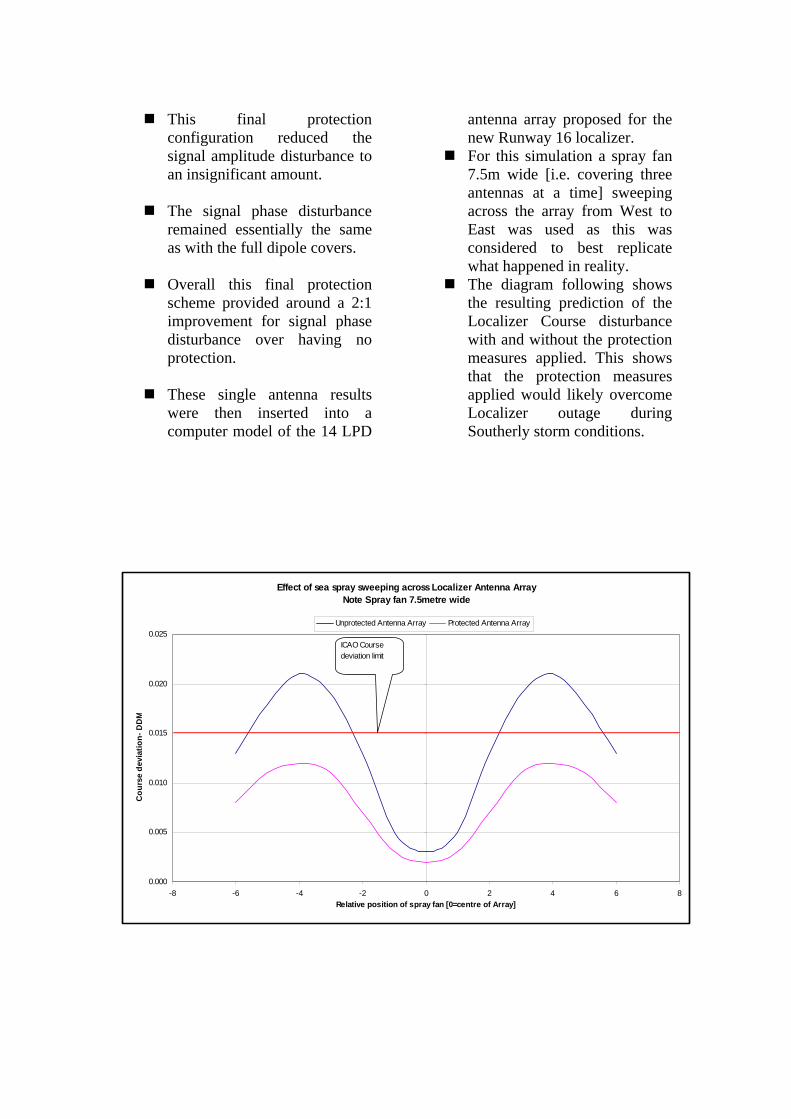
These single antenna results
were then inserted into a computer model of the 14 LPD
antenna array proposed for the new Runway 16 localizer. For this simulation a spray fan
7.5m wide [i.e. covering three antennas at a time] sweeping across the array from West to East was used as this was considered to best replicate what happened in reality. The diagram following shows
the resulting prediction of the Localizer Course disturbance with and without the protection measures applied. This shows that the protection measures applied would likely overcome Localizer outage during Southerly storm conditions.
Effect of sea spray sweeping across Localizer Antenna ArrayNote Spray fan 7.5metre wide
0.000
0.005
0.010
0.015
0.020
0.025
-8 -6 -4 -2 0 2 4 6 8Relative position of spray fan [0=centre of Array]
Cou
rse
devi
atio
n- D
DM
Unprotected Antenna Array Protected Antenna Array
ICAO Course deviation limit
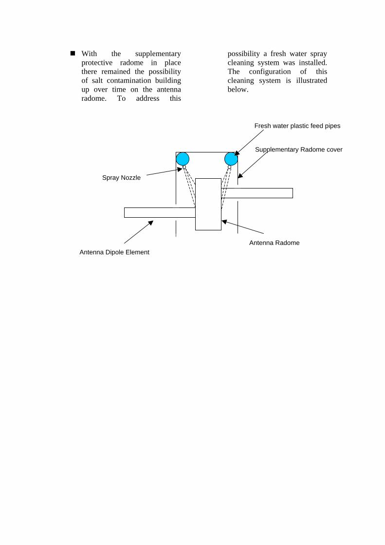
With the supplementary
protective radome in place there remained the possibility of salt contamination building up over time on the antenna radome. To address this
possibility a fresh water spray cleaning system was installed. The configuration of this cleaning system is illustrated below.
Fresh water plastic feed pipes
Spray Nozzle
Antenna Dipole Element Antenna Radome
Supplementary Radome cover
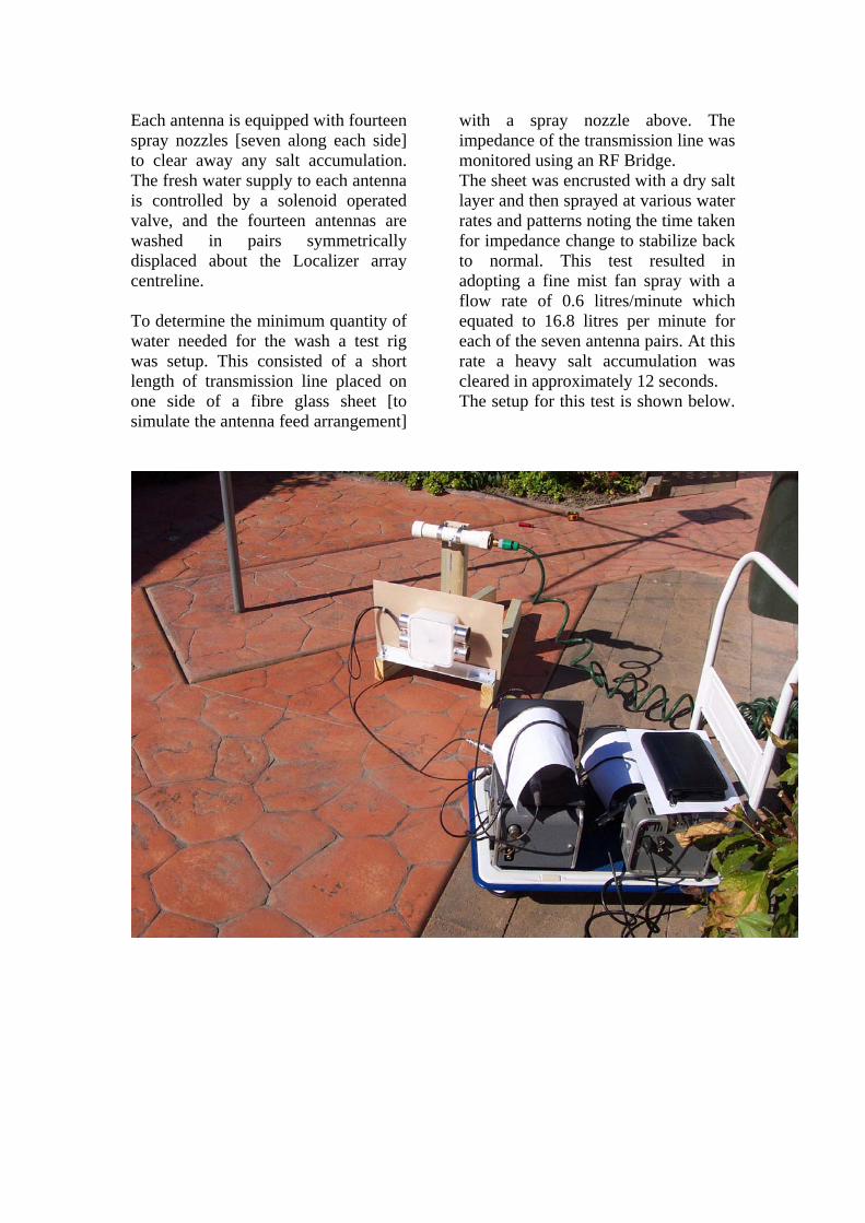
Each antenna is equipped with fourteen spray nozzles [seven along each side] to clear away any salt accumulation. The fresh water supply to each antenna is controlled by a solenoid operated valve, and the fourteen antennas are washed in pairs symmetrically displaced about the Localizer array centreline. To determine the minimum quantity of water needed for the wash a test rig was setup. This consisted of a short length of transmission line placed on one side of a fibre glass sheet [to simulate the antenna feed arrangement]
with a spray nozzle above. The impedance of the transmission line was monitored using an RF Bridge. The sheet was encrusted with a dry salt layer and then sprayed at various water rates and patterns noting the time taken for impedance change to stabilize back to normal. This test resulted in adopting a fine mist fan spray with a flow rate of 0.6 litres/minute which equated to 16.8 litres per minute for each of the seven antenna pairs. At this rate a heavy salt accumulation was cleared in approximately 12 seconds. The setup for this test is shown below.

Jet Blast protection. The largest aircraft using the
airport is the Boeing 767. A plot of the Jet blast velocity versus distance is shown below.
It will be seen that at 53m
distance behind the aircraft the exhaust air velocity is greater than 100mph.
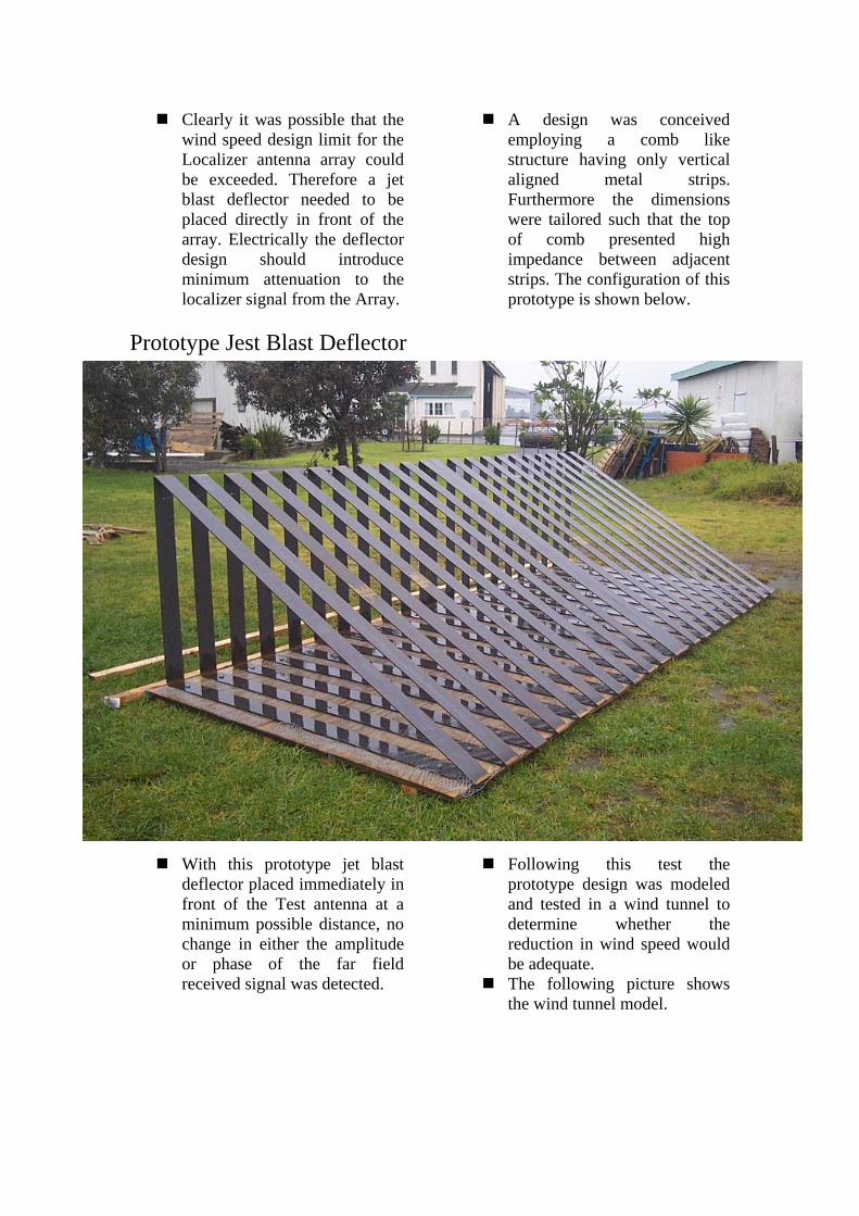
Clearly it was possible that the
wind speed design limit for the Localizer antenna array could be exceeded. Therefore a jet blast deflector needed to be placed directly in front of the array. Electrically the deflector design should introduce minimum attenuation to the localizer signal from the Array.
A design was conceived employing a comb like structure having only vertical aligned metal strips. Furthermore the dimensions were tailored such that the top of comb presented high impedance between adjacent strips. The configuration of this prototype is shown below.
Prototype Jest Blast Deflector
With this prototype jet blast deflector placed immediately in front of the Test antenna at a minimum possible distance, no change in either the amplitude or phase of the far field received signal was detected.
Following this test the prototype design was modeled and tested in a wind tunnel to determine whether the reduction in wind speed would be adequate. The following picture shows
the wind tunnel model.
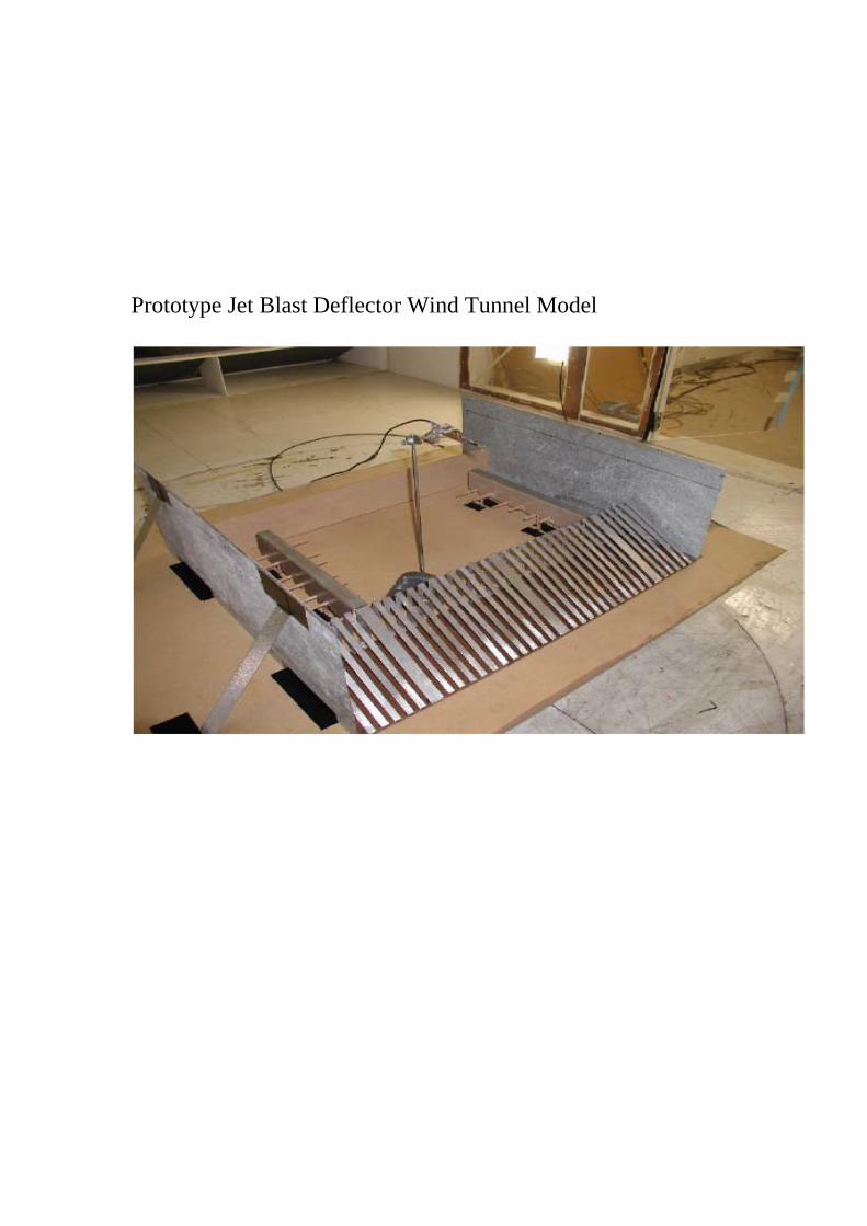
Prototype Jet Blast Deflector Wind Tunnel Model

Having completed the design concepts it was then the task of the Structural engineers to replicate the basic form of the prototype deflector into a practical piece of hardware
complete with the necessary shear pins to provide for a frangible structure. The following pictures show
the final design as installed on site.

It was a requirement that there be no interruption to the ILS service during the period of this RESA construction. To achieve this much of the
Civil Work was carried out late at night. The new Localizer had to be
installed and commissioned into service before the previous Localizer was removed. As part of this process a reinforcing mesh screen was laid along the edge of the roadway underpass to ensure that this edge was electrically parallel to the New Localizer antenna array until the gulley remaining between the underpass and the old localizer had been backfilled.

Finale
To date sea spray dump has not caused shutdown of the new Localizer.
Flight Inspection recorded the
coverage to be slightly better than for the previous Localizer installation and comfortably meets the ICAO 18/10nm alternative criteria.
The testing to prove the concept was conducted during 2004 and 2005. The civil works began in 2006 and the new Localizer was commissioned in 2007.
Work has commenced to install
a similarly configured Localizer but without the sea spray protection, on the opposite approach [Runway 34]
Mel King is a Navigation Aids Engineer heading the New Zealand Airways Corporation Flight Inspection Unit. He has also been a serving member of the International Committee for Airspace Standards and Calibration since 1996.

1
C U R R I C U L U M V I T A E
NAME: Mel King NATIONALITY: New Zealand BORN: 12th May 1932 APPOINTMENT: Manager Flight Inspection and Systems Engineer FIRM: Airways Corporation of New Zealand Ltd BACKGROUND Mel King is a professional engineer with an electrical and electronics engineering background spanning some 50 years and focusing on radio-navigation systems and flight inspection. He has been widely involved in a number of major projects during this period featuring all aspects of planning and implementation. His expertise and experience includes financial management, maintenance activities and responsibility for those sections providing air navigation services. Mr King has held high office in government civil aviation administration and management, including appointments as Assistant Director of Civil Aviation and Chief Engineer. He has been an adviser with the International Civil Aviation Organisation (ICAO) on behalf of the United Nations Development Program (UNDP) and currently is a serving member on the International Committee for Airspace Standards and Calibration. KEY EXPERIENCES • Assistant Director Technical Development with the then Civil Aviation Department of the New
Zealand Ministry of Transport, responsible for technical and engineering standards and compliance with ICAO requirements for an air traffic services system.
• Chief Engineer Navigation Aids with the New Zealand Civil Aviation Department, responsible
for planning, procurement and installation of navigation facilities in New Zealand and the Pacific Islands through the New Zealand overseas aid development programme.
• Development of life cycle cost management standards for technical equipment. • Negotiating flight inspection contracts for navigation aid checking. • Experiences at all aspects of project management and its related definition, evaluation, cost-
benefit, schedule, negotiating, financial and analytical skills. • Vice-Chairman of the International Committee for Airspace Standards and Calibration.

2
• Development and implementation of Global Navigation Satellite System flight inspection
capability. PROFESSIONAL MEMBERSHIPS Member, Institution of Professional Engineers of New Zealand (MIPENZ)
Member, Institution of Electrical Technology IET(United Kingdom).
EXPERIENCE 1991-Present Airways Corporation of New Zealand Ltd 1991-Present Systems Engineer Flight Inspection and Manager Flight Inspection Responsible for:
managing flight inspection services defining and maintaining flight inspection standards and procedures analysing and maintaining flight inspection records researching flight inspection methods and system undertaking flight inspection engineering duties throughout New
Zealand and Indo-Asia-Pacific regions. 1990-91 Self employed Consulting engineer in the aviation industry specialising in radio navigation
aids and flight inspection 1986-89 International Civil Aviation Organization Expert Appointment with ICAO as Flight Calibration (Inspection) Adviser, under the
United Nations Development Programme, to provide technical assistance in Tanzania, East Africa. The purpose of this position was to establish a Flight Inspection Unit for the Eastern-Southern African States.
1945-1986 New Zealand Ministry of Transport, Civil Aviation Department 1986 Assistant Director Technical Development Responsible for the overall management for communications, navigation and
surveillance systems and airfield electrical systems for New Zealand. 1983-1985 Chief Engineer Navigation Aids Responsible for planning, procurement and implementation of radio
navigation facilities in New Zealand, and in Pacific islands states through the New Zealand overseas aid development programme.

3
1945-1983 Aeronautical Systems Engineering Positions (various) Employed in a variety of positions with the New Zealand Ministry of
Transport, specialising in aeronautical electrical and electronic systems.