input/output specifications for control data file7 input amplifier circuit 20 8 output amplifier...
TRANSCRIPT

INPUT/OUTPUT SPECIFICATIONS FOR
CONTROL DATA 8092 TeleProgrammer

INPUT/OUTPUT SPECIFICATIONS FOR
CONTROL DATA 8092 TeleProgrammer
lOP 105a
REVISION A
3/11/64 Manual printed.
Publication No. 36810500A
© 1964 by Control Data Corporation
Printed in the United States of America
REVISION RECORD DESCRIPTION
-
Address comments concerning this manual to: Control Data Corporation Technical Publications 4201 N. Lexington Ave. St. Paul, Minnesota 55112
. or use Comment Sheet in the back of this manual. .
CONTENTS
Page
TELEPROGRAMMER INPUT/OUTPUT SPECIFICATIONS 1
Interrupt 2 Select Codes 3 Communication Lines 7 Normal Input/Output 10 Buffered Input/Output 13
TELEPROGRAMMER COMMUNICATION CIRCUITS 19
Input Circuits 19 Output Circuits 20 Cable Connectors 22
FIGURES
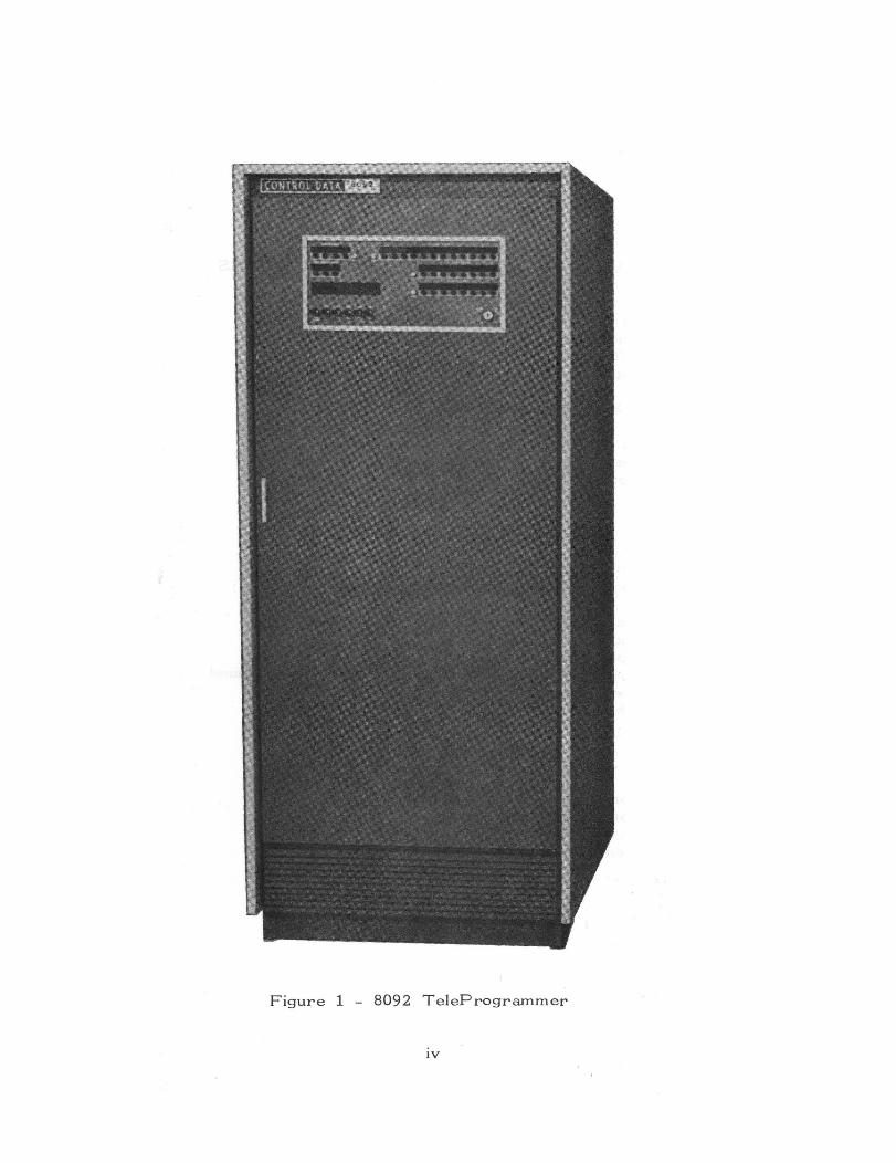
1 8092 TeleProgrammer (Photograph) IV
2 Block Diagram 8092 TeleProgrammer System 2 3 Normal Input 8092 12 4 Normal Output 8092 12 Sa Buffered Input 8092 15 5b Buffered Output 8092 15 6 Maximul1) PE?rmissible Transfer Rates Using Buffer Channel 16 7 Input Amplifier Circuit 20 8 Output Amplifier Circuit 22
TABLES
1 Communication Lines, Output Cable 2 Communication Lines, Input Cable 3 Cable Designations 4 Pin Assignments
111
5 6 7 9
-- ~ ..... - '" \.,~_J! !,\._.L __ J. 7~- J
l - - j !J. - J. "'~::'iJ- __ ) !L_.t __ J. __ J
"" .~:. ....0·
Figure 1 - 8092 TeleProgrammer
IV
The input/output (I/O) specific ations for the CO N TRO L DA T A*
8092 TeleProgl'arnmer apply to all device9 which connect with
the TelePrograrnmer. This specification is written to allow a
minimum data exchange time consistent with accepted engineering
practices and moderate hardware requirements.
The 8092 has a four-level interrupt and a buffered I/O. The
latter permits the TelePrograrnmer to continue high-speed compu-
tation while communicating with external equipment. The minImum
system may be expanded to include the following external equipment:
Additional magnetic tape stations I/O typewriters Punched card readers, punches, arid low speed line printers High speed printers - 1000 lines/minute Plotting and digital display equipment Analog to digital and digital to analog equipment Two or more CONTROL DATA TelePrograrnmers operating in a satellite- system
All information is measured as binary "1" and "0" voltage levels,
nominal ground level (-0.5v) constituting a "1", and -16v a "0".:>',0:<
Voltage is measured at the output terminals of the TelePrograrnmer
and the external equipment.
* Registered Trademark of Control Data Corporation ** See page 18 for tolel"ances on these voltage levels.
1

INTERRUPT
Certain internal and external conditions arise which make it
desirable for the main program to be notified of their presence.
An interrupt is the program signal which transfers computer con-
trol to some fixed location in memory without losing the information
needed to return to the main program.
Z REGISTER
-'"'"
NORMAL INPUT
LINES NORMAL OUTPUT
. r- I I--3 LINES
r? BFR BUSY
)- BFR BUSY
BUFFER . ./ ~. BUFFER
~ . '-. . BUFFER
INPUT UNES ·T ,. REGISTE"R OUTPUT LINES
INPUT OUTPUT .BUFFER BUFFER
ACTIVE ACTIVE
Figure 2 8092 Input/Output System
2

The 8092 has four interrupt lines: two internal, 10 and 20, and
two external, 30 and 40. When an external equipment generates
an interrupt the TeleProgrammer may enter the interrupt routine
if the interrupt lockout is not on. The TeleProgrammer program
may send a status request to all equipment which might have gen
erated the interrupt to determine which interrupted. This status
request is a signal to the external equipment to turn off the interrupt,
or the signal in the external device may be turned off by a function
response.
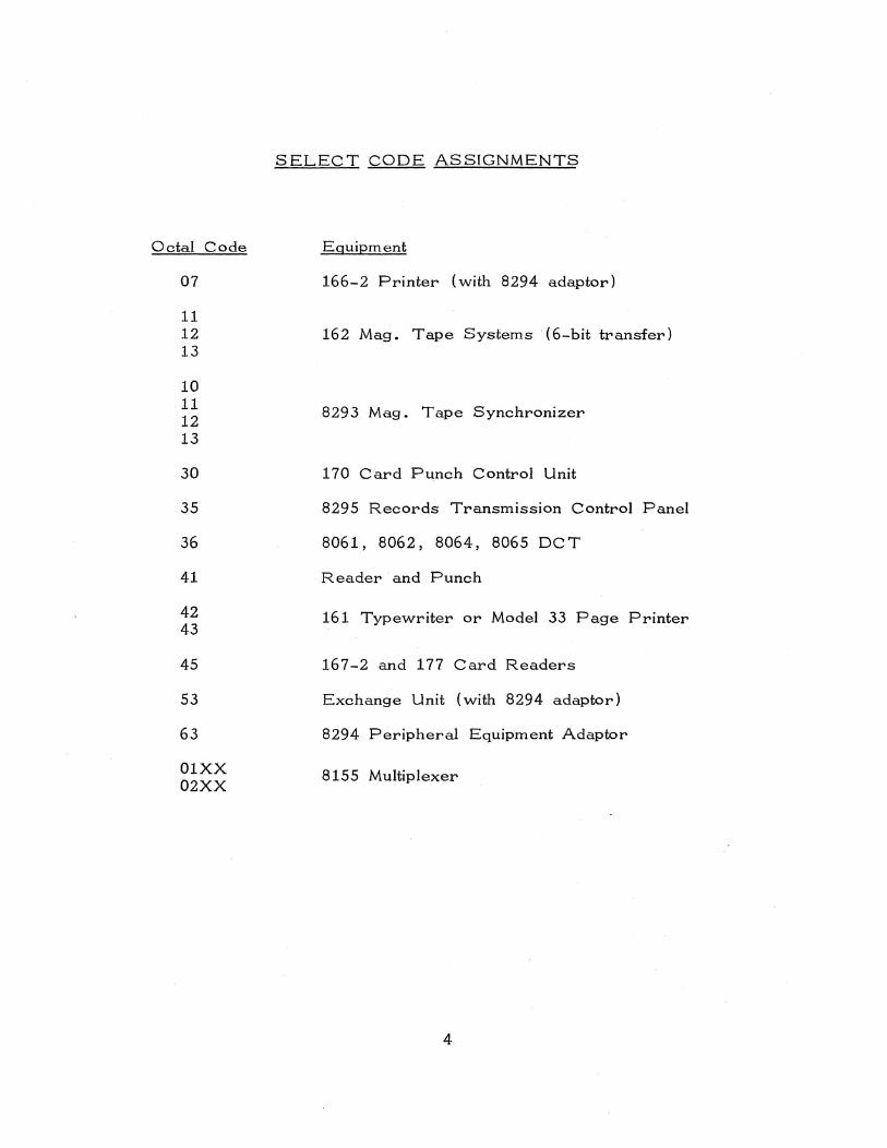
SELECT CODES
The TeleProgrammer selects the external equipment for I/O
operation by the use of select code~. The I/O operation is
initiated by a 75 instruction which selects a 12-bit code and places
it on the output lines with a function ready signal. The upper 6
master bits (unit designator) select the external equipment, and the
lower 6 bits (function designatGr) designate the function.
Master bits for select codes must be umque for each 8092 I/O
equipment. Master bits given below are in octal and quartic
(base 4) notation, and represent devices currently available. It.
is recommended that the 8092 Engineering Department of Control
Data Corporation be consulted before assigning master bits for
select codes on new equipment. This will minimize the chance of
select code duplication through future expansion of an existing
system.
3
Octal Code
07
11 12 13
10 11 12 13
30
35
36
41
42 43
45
53
63
01XX 02XX
SELECT CODE ASSIGNMENTS
Equipment
166-2 Printer (with 8294 adaptor)
162 Mag. Tape Systems {6-bit transfer)
8293 Mag. Tape Synchronizer
170 Card Punch Control Unit
8295 Records Transmission Control Panel
8061, 8062, 8064, 8065 OCT
Reader and Punch
161 Typewriter or Model 33 Page Printer
167-2 and 177 Card Readers
Exchange Unit (with 8294 adaptor)
8294 Peripheral Equipment Adaptor
8155 Multiplexer
4
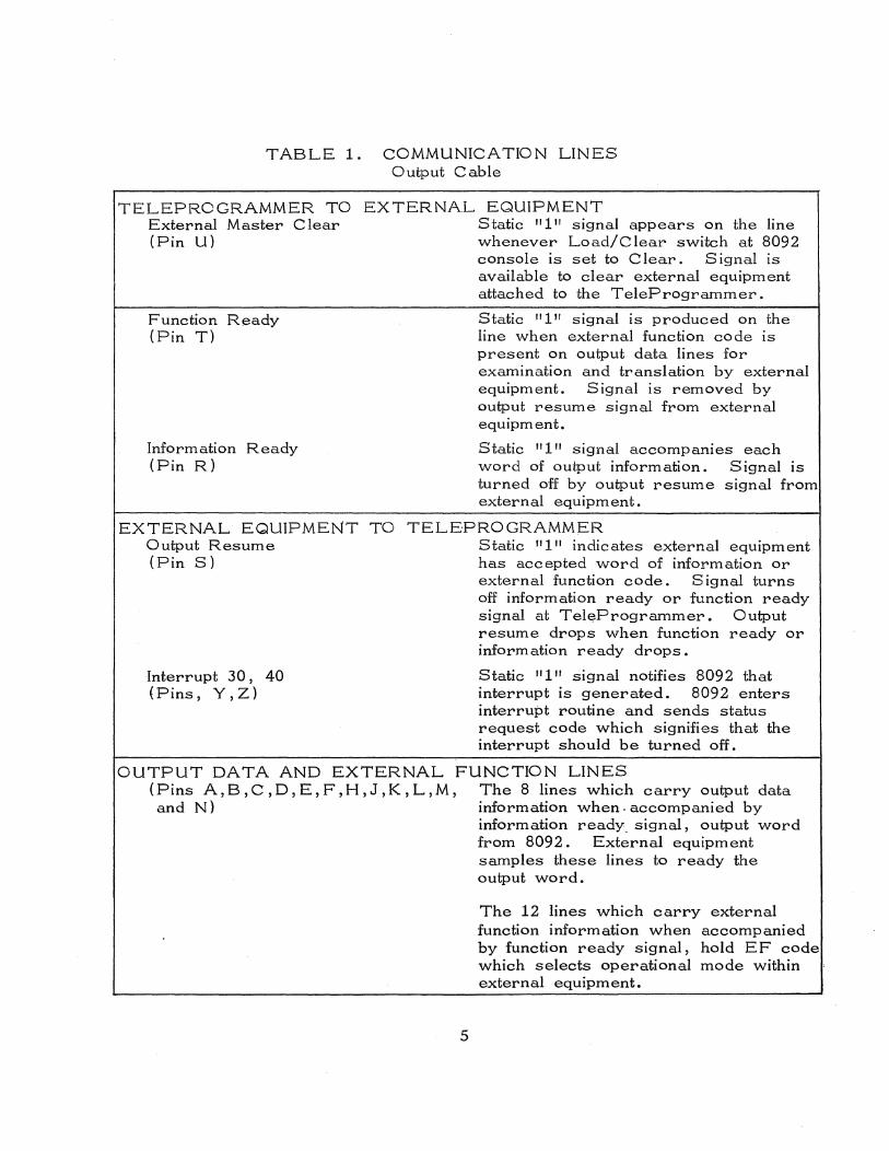
TABLE 1. COMMUNICATION LINES Output Cable
TELEPROGRAMMER TO EXTERNAL EQUIPMENT External Master Clear Static "1 I' signal appears on the line (Pin U) whenever Load/Clear switch at 8092
console is set to Clear. Signal IS
available to clear external equipment attached to the TeleProgrammer.
Function Ready (Pin T)
Information Ready (Pin R)
Static "1" signal is produced on the line when external function code is present on output data lines for examination and translation by external equipment. Signal IS removed by output resume signal from external equipment.
Static "1" signal accompanies each word of output inform ation. Signal IS
turned off by output resume signal from external equipm ent.
EXTERNAL EQUIPMENT TO TELEPROGRAMMER Output Resume (Pin S)
Interrupt 30, 40 (Pins, Y, Z)
Static "1" indicates external equipment has accepted word of information or external function code. Signal turns off information ready or function ready signal at Tel~Programmer. Output resume drops when function ready or information ready drops.
Static "1" signal notifies 8092 that interrupt is generated. 8092 enters interrupt routine and sends status request code which signifies that the interrupt should be turned off.
OUTPUT DATA AND EXTERNAL FUNCTION LINES (Pins A,B,C,D,E,F,H,J,K,L,M, and N)
5
The 8 lines which carry output data information when. accompanied by information ready. signal, output word from 8092. External equipment samples these lines to ready the output word.
The 12 lines which carry external function information when accompanied by function ready signal, hold EF code which selects operational mode within ' external equipment.
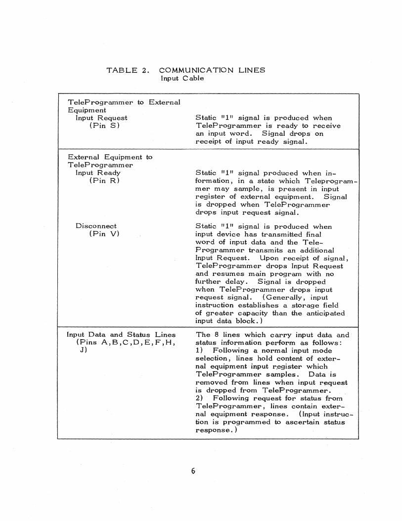
TABLE 2. COMMUNICATION LINES Input Cable
TeleProgrammer to External Equipment
Input Request (Pin S)
External Equipment to TeleProgrammer
Input Ready (Pin R)
Disconnect (Pin V)
Input Data and Status Lines (Pins A,B,C,D,E,F,H, J)
Static "1" signal is produced when TeleProgrammer IS ready to receIve an input word. Signal drops on receipt of input ready signal.
Static "1" signal produced when information, In a state which Teleprogrammer may sample, is present in input register of external equipment. Signal IS dropped when TeleProgrammer drops input request signal.
Static "1" signal is produced when input device has transmitted final word of input data and the TeleProgrammer transmits an additional Input Request. Upon receipt of signal, TelePrograminer drops Input Request and resumes main program with no further delay. Signal is dropped when TeleProgrammer drops input request signal. ( Generally, input instruction establishes a storage field of greater capacity than the anticipated input data block.)
The 8 lines which carry input data and status information perform as follows: 1) Following a normal input mode selection, lines hold content of external equipment input r.egister which TeleProgrammer samples. Data is removed from lines when input request is dropped from TeleProgrammer.
6·
2) Following request for status from TeleProgrammer, lines contain external equipment response. (Input instruction is programmed to ascertain status response. )
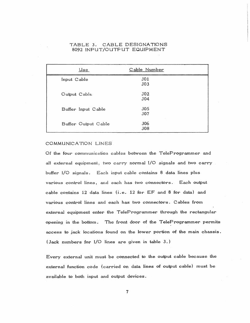
TABLE 3. CABLE DESIGNATIONS 8092 INPUT/OUTPUT EQUIPMENT
Input Cable
Output Cable
Buffer Input Cable
Buffer Output Cable
COMMUNICATION LINES
Cable Number"
J01 J03
J02 J04
J05 J07
J06 J08
Of the four communication cables between the TeleProgrammer and
all external equipment, two carry normal I/O signals and two carry
buffer I/O signals. Each input cable contains 8 data lines plus
various control lines, and each has two connectors. Each output
cable contains 12 data lines (i.e. 12 for EF and 8 for data) and
various control lines and each has two connectors. C abies from
external equipment enter the TeleProgrammer through the rectangular
opening in the bottom. The front door of the TeleProgrammer permits
access to jack locations found on the lower portion of the m"ain chassis.
(Jack numbers for I/O lines are given in table 3.)
Every external unit must be connected to the output cable because the
external function code (carried on data lines of output cable) must be
available to both input and output devices.
7
The total number of devices attached to one line is limited by maximum
cable length and power capacities of the transistors on the amplifier
cards. Five pieces ·of equipment may be attached to the normal
channel . and five to the buffer· channel.
Equipment attached to the buffer lines may be addressed directly if
no buffer operation IS in progress. Consequently anyone of up to
ten external pieces of equipment may be addressed by normal I/O
if the buffer is not busy.
8
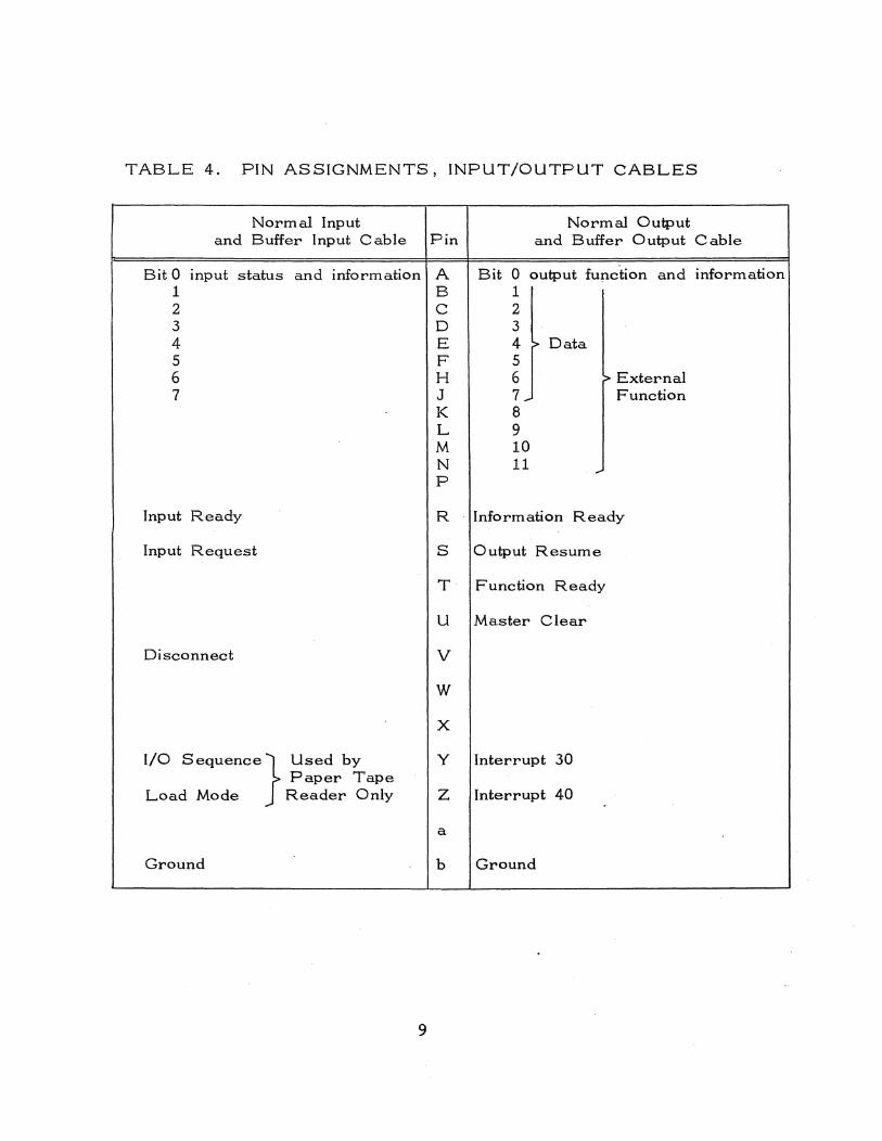
TABLE 4. PIN ASSIGNMENTS, INPUT/OUTPUT CABLES
BitO 1 2 3 4 5 6 7
Normal Input and Buffer Input Cable Pin
input status and information A B C D E F H J K L M N P
Input Ready R
Input Request
Disconnect
I/O sequence} Used by Paper Tape
Load Mode Reader Only
Ground
9
S
T
U
V
W
X
Y
Z
a
b
Normal Output and Buffer Output Cable
Bit o output fup.ction and information 1 2 3 4 ~ Data 5 6 :> External 7 ... 8 9 10 11
Function
Information Ready
Output Resume
Function Ready
Master Clear
Interrupt 30
Interrupt 40
Ground
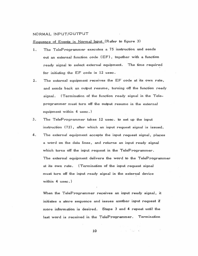
NORMAL INPUT/OUTPUT
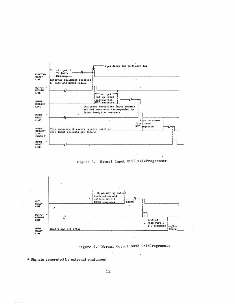
Sequence of Events in Normal Input (Refer to figure 3)
1. The TeleProgrammer executes, a 75 instruction and sends
out an external function code (EF), together with a function
ready signal to select external equipment. The time required
for initiating the EF code is 12 usec.
2. The external equipment receives the EF code at its own rate,
and sends back an output resume, turning off the function ready
signal. (Termination of the function ready signal in the Tele-
programmer must turn off the output resume in the external
equipment within 4 usec.)
3. The TeleProgrammer takes 12 usec. to set up the input
instruction (72), after which an input request signal is issued.
4. The external equipment accepts the input request signal, places
a word on the data lines, and returns an input ready signal
which turns off the input request in the TeleProgrammer.
The external equipment delivers the word to the TeleProgrammer
at its own rate. (Termination of the input request signal
must turn off the input ready signal in the external device
within 4 usec.)
When the TeleProgrammer receives an input ready signal, it
initiates a store sequence and issues another input request if
more information is desired. Steps 3 and 4 repeat until the
last word is received in the TeleProgrammer. Termination
10
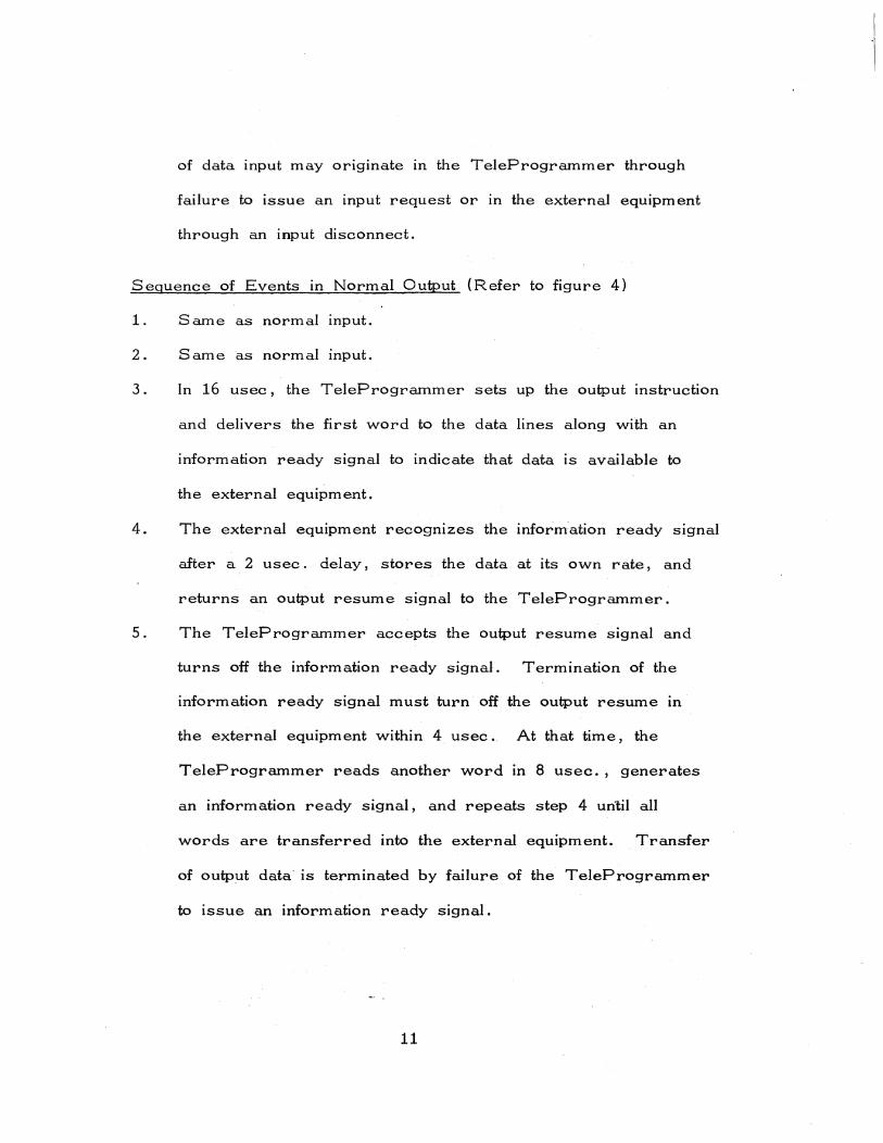
of data input may originate in the TeleProgrammer through
failure to issue an input request or in the external equipment
through an input disconnect.
Sequence of Events in Normal Output (Refer to figure 4)
1. Same as normal input.
2. Same as normal input.
3. In 16 usec, the TeleProgrammer sets up the output instruction
and delivers the first word to the data lines along with an
information ready signal to indicate that data is available to
the external equipment.
4. The external equipment recognizes the information ready signal
after a 2 usec. delay, stores the data at its own rate, and
returns an output resume signal to the TeleProgrammer.
5. The TeleProgrammer accepts the output resume signal and
turns off the information ready signal. Termination of the
information ready signal must turn off the output resume In
the external equipment within 4 usec. At that time, the
TeleProgrammer reads another word In 8 usec., generates
an information ready signal, and repeats step 4 until all
words are transferred into the external equipment. Transfer
of output data is terminated by failure of the TeleProgrammer
to issue an information ready signal.
11
FUNCTION REAOY LINE'
OUTPUT * RESUME LINE
INPUT REQUEST LINE
INPUT READY LINE
INPUT REQUESt LINE (WORD 2)
INPUT READY LINE
INFO READY LINE
r-- 2 1'0' delay due to H card lag
- 12 p.s--I ( :+: ~~c~~~t. f i I
ExternaL equipmel)t receives I L... ________________________________________ _
EF code and sends Resume :
~----~~r--~----~rnl-------~r_------~-------------'1 " --'-17 p.s--I : Set up input , I instruction i ,DBC seQuence f----;l'---____ _
Equipment recop,nize, input request : and delivers word (accompanied by I
JJ
Input Ready) at own'rate ~
~I--------'------
This sequence of events repeats until no more input requests are issuen
8 f'S to store first! word S'C' ~equence ':L
I , I ,
~--~!.'~f------~~-----------------------------~
Figure 3. Nor~al Input B092 releProgrammer
, 1 1 Lli p.s set up outpllt , instruction and I • i deliver word 1 I
ODCe
, OUTPUT • RESUME ~------~Jrt--------------------------------------~-----J LINE 12.8p.S
Read word 2
INFO' READY LINE
B'C'sequence tL Word "2 and all after ~~~~~~~~~~ ______________ _,------------------~----------~·Store
Figure 4. Normal Output B092 TeleProgrammer
* Signals generated by external equipment
12
BUFFERED INPUT/OUTPUT
Sequence of Events in Buffered Input {Refer to figure Sa}
1. Same as normal input.
2. Same as normal input.
3. The TeleProgrammer reads the 70 instruction in 4 usee. It
then generates an input request, releasing the TeleProgrammer
for computation.
4. The external equipment accepts the input request signal, places
a word on the data lines, and generates an input ready signal.
S. The TeleProgrammer accepts the input ready signal and
stores the word. ':' Recognition of the input ready signal
terminates the input request which turns off the input ready
signal in the external equipment. {Termination of the input
request signal must turn off the input ready signal within
4 msec.}
6. The TeleProgrammer Issues another input request and steps
4 and S repeat until all words are buffered into the TeleProgram-
mer.
Sequence of Events in Buffered Output {Refer to figure" Sb}
1. Same as normal input.
':' It may take the TeleProgrammer up to 18 usec. to recognize the input ready and store the word, depending on which cycle the TeleProgrammer is in when the input ready signal occurs.
13
2. Same as normal input.
3. The TeleProgrammer reads the 71 instruction in 4 usec.
and initiates a buffer cycle to place the first word on the
data lines and issue an information ready signal. The Tele-
Programmer is then free for computation.
4. The external equipment accepts the information ready signal
and data at its own rate and returns an output resume signal.
5. Recognition of the output resume signal initiates another buffer
cycle and terminates the information rea?y signal. * 6. Termination of the information ready signal in the TeleProgrammer
turns off the output resume signal in external equipment.
(Output resume must turn off within 4 msec.)
7. Steps 3-5 are repeated for each word until all words are
buffered out of the TeleProgrammer.
* It may take the TeleProgrammer up to 18 usec. to recognize the output resume and put the next word on the output lines, depending on which cycle the TeleProgrammer is in when the output resume occurs.
14

FUNCTION READY LINE
OUTPUT .. RESUME LINE
INPUT REQUEST LINE
INPUT " READV LINE
INPUT REClUEST LINE
INPUT .. READY LINE
INFO READY I.lNE
•
12 P.s 7S instructionl ,r--- 2J.l.s delay due to M card lap, or.-- ~ ;.----1 ~r ---:--'v . Dec' sequence 1 .IJ I I
I L+J--------~-------------------------------I ,
I l :ea/I r-_____ ~~r-------~r-l 70
.JJ : 4 slset Buffer FF and I ~ I for computation
release 8082
rW_o_r_d_l __________________ !~~ I---/~~ ______________________________ _
r n r---------~J/~-------------~~I L-________________ __
I I I
"lord 2 : .. I
,lSJ.l.S max • . 6 J.l.s min. n
~-----~JJ~/----------------------------~--~-------~ ~-----
Figure Sa. Buffered Input, 8092 TeleProgrammer
WOTd I ~
OUTPUT" . I.: n RESUME
LINE I I
I , ., INFO Word 2 I REAOY . LINE c
18J4!1 !'lax.
OUTPUT • 6 JLs min. n RESUME (
LINE J
Figure Sb. Buffered Output, 8092 TeleProgramnier
* Signals generated by external equipment
15
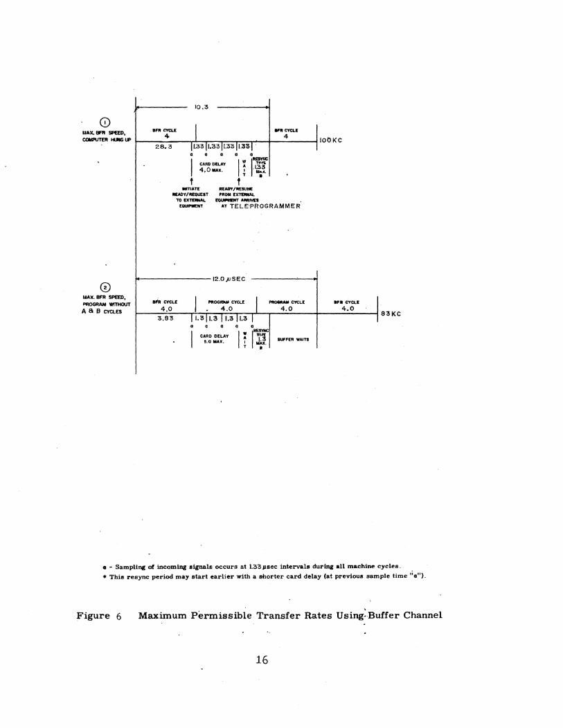
o MAl(. BFR SP£ED, COMPUTER HI.ftG lI'
CD MAX. BFR SPEED, PflOGRAM WITHOUT A a B CYCLES
10.3
e"" CYCLE I WltCYCL[
4> 4
28.3 11.33 11,3311.33 11.3<>1'
• • • a 0
I CAfiODElAV IWI~ 4,0 ...... ~ .1.33 T ~A.
f f INITIATE RVJIT /II£SIJtIE
II£AnY/MQUEST 'ROM EX1DIIW. TO EXTDWAL. ~A"'JYES
EQUlPIIIE!fT AT TELE'PROGRAMMER
12.0)JSEC
BP1tCYCLE I PROOftN' CYCLE I PRoeM"" CYCLE
4.0 4.0 4.0
3.83 11•3 11.3 11.311.3 I 0 • • a •
I CARD DELAY 5.0 MAX . IWI~ t ~~ BUfFER WAITS
l'ObK'
an cYCLE I 4.0
I 83KC
• - Sampling of incoming signals occurs at 1.33 Jlsec intervals during all machine cycles.
* This resync period may start earlier with a shorter card delay (at previous sample time ';0").
Figure 6 Maximum Permissible Transfer Rates Using:Buffer Channel
16

TELEPROGRAMMER COMMUNICATION CIRCUITS
17

TELEPROGRAMMER COMMUNICATION CIRCUITS
In communicating with external devices the TeleProgrammer signals
undergo a level change to minimize effects of cable impedance. The
TelePrograrnmer signals are refepred to as logic levels, the cable
signals as line levels. The binary representation for the two levels
are:
Logic "1" -3.0v (± 0.2Sv) "0" -O.Sv (± 0.2Sv)
Line "1" -O.Sv (+ 0.2Sv»:' "0" -16v (± 2.Sv)
Both line and logic levels are encountered in the input and output
amplifier cards. All external equipment control signals are resyn-1
chronized upon entering the TeleProgrammer.
INPUT CIRCUITS
In the schematic diagram of the input amplifier circuit (figure 7),
resistor R01 and the -20v supply hold the input to the circuit (point a)
to line 110" when no input signal is supplied, or when no data or
control line is tied to the circuit. If a line 11111 is supplied to the
input pin, the base of Q01 (point b) rises due to the voltage divider
action of R02, R06, and ROB. Subsequently 001 stops conducting,
and the output to the computer circuits represents a logic 11111.
):~ Tolerances given are for Control Data equipment. When other equipment is connected to Control Data TeleProgrammers, the following variation may be tolerated on the "1" line level: + O. Sv, -2. Sv.
19
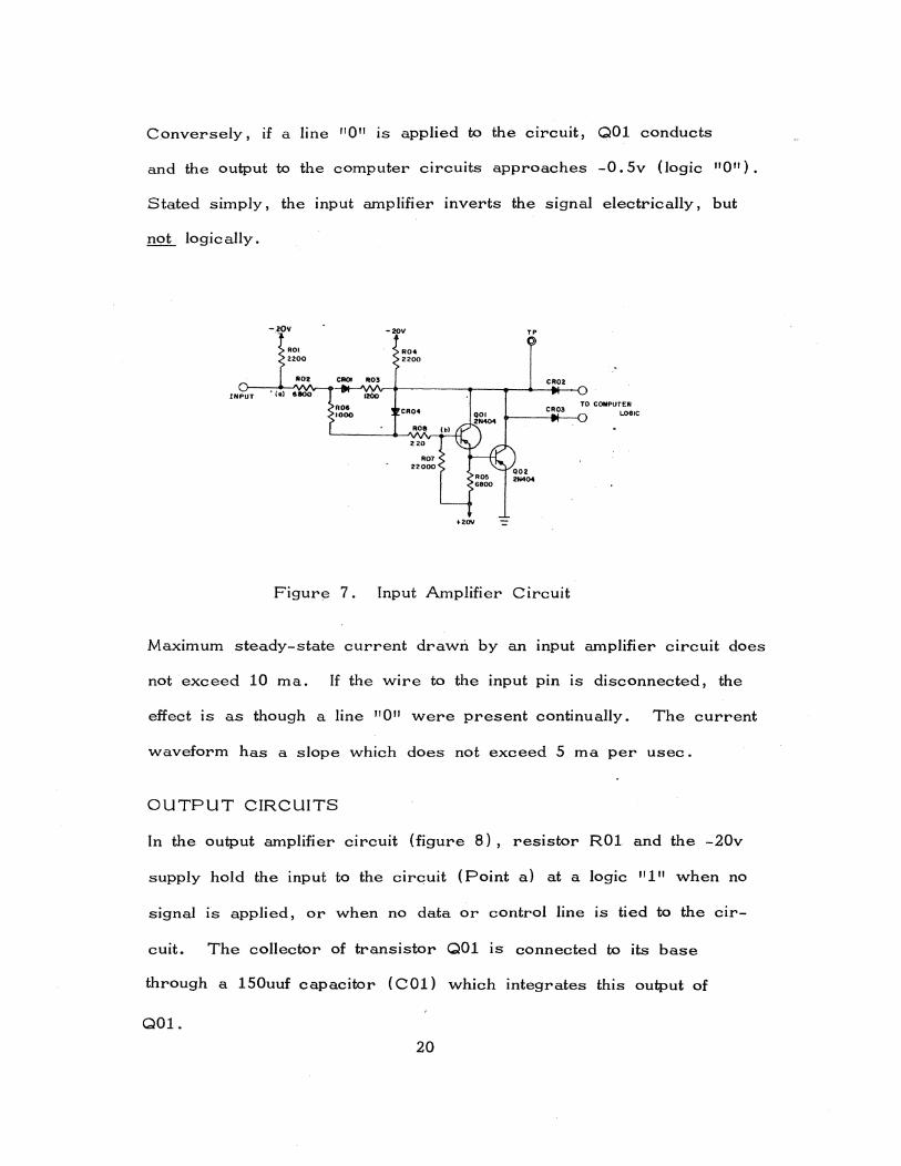
Conversely, if a line "0" is applied to the circuit, 001 conducts
and the output to the computer circuits approaches -0.5v (logic "0").
Stated simply, the input amplifier inverts the signal electrically, but
not logically.
INPUT
ROI 2200
RO.
• (a) 6800
CROI R03
ROC 1000
IzOo
-20V
RO. 2200
CR04
ROe
220
R07 22000
TP
CR02
CR03
+2OV -=
Figurl3 7. Input Amplifier Circuit
TO COMPUTER LOGIC
Maximum steady-state current drawn by an input amplifier circuit does
not exceed 10 rna. If the wire to the input pin is disconnected, the
effect is as though a line "0" were present continually. The current
waveform has a slope which does not exceed 5 rna per usec.
OUTPUT CIRCUITS
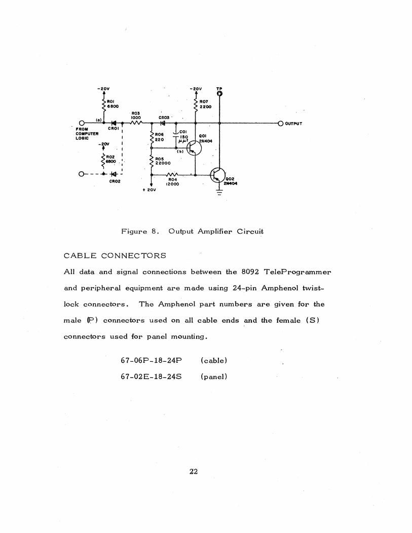
In the output amplifier circuit (figure 8), resistor ROl and the -20v
supply hold the input to the circuit (Point a) at a logic "1" when no
signal is applied, or when no data or control line is tied to the clr-
cuit. The collector of transistor 001 IS connected to its base
through a 150uuf capacitor (COl) which integrates this output of
001.
20
When a logic 111" is applied to either input pin, aOl turns on,
placing a low impedance between ground and the output line. C apa
citor COl tends to oppose the initial conduction of QOl by feeding
back a signal less positive than that initially placed on the base.
When COl is fully charged, 001 reaches full conduction and the
output rises to -0. Sv (line "1 II}. If a logic "0" is applied to this
circuit, the voltage divider action of the circuit turns off Q01, and
the output stabilizes at -16v (line 110 11 ). Stated simply, the output
amplifier inverts the signal electrically, but not logically.
The output amplifier need supply no more than IO rna to any input
amplifier in another piece of equipment. Transition time of the
signal waveform from the output amplifier circuit is 2 usec. minimUm,
4 usec. maximum. Total line capacity may vary between 0 and
0.002 ufo
Voltage level rise and fall rates are Bv/usec.; d-c resistance of
cable ground return must not exceed O. 5 ohm. All data lines are
stable before information is sampled.
21
-20V -20V TP
ROI 6800
ROll
(a) 1000 OUTPUT
"ROM CROI I COMPUTER LOGIC
_2OV f
.~~ I
I
1 0--- ..... *-
CR02 R04 12000
+ 20V --
Figure 8. Output Amplifier Circuit
CABLE CONNECTORS
All data and signal connections between the 8092 TeleProgrammer
and peripheral equipment are made using 24-pin Amphenol twist-
lock connectors. The Amphenol part numbers are given for the
male (p) connectors used on all cable ends and the female (S)
connectors used for panel mounting.
67-06P-18-24P (cable)
67 -02E-18-24S (panel)
22

CABLE CONNECTORS
All data and signal connections between the 8092 TeleProgrammer and peripheral equip~ent are made using 24-pin Amphenol twist-lock connectors. The Amphenol part numbers are given for the male (P) connectors used on all cable ends and the female (S) connectors used for panel mounting.
67-06P-l8-24p
67-02E-l8-24S
23
(cable)
(panel)
COMMENT SHEET
MANUAL TITLE __ 8_0_9_2_T_e_l_e_P_r_o-,g",-r_a_m_m_e_r_I_n ...... p,-u_t...;..l_o_u_t ..... p ..... u_t_S"'-p_e_c_if_i_c_a_t_io_n_s __ _
PUBLICATION NO. __ 3_6_8_1_0_5_0_0 ____ _ REVISION __ A ____ _
FROM: NAME: ________________________________ _
BUSINESS ADDRESS: __________________________________________ __
COMMENTS: This form is not intended to be used as an order blank. Your evaluation of this manual will be welcomed by Control Data Corporation. Any errors, suggested additions or deletions, or general comments may be made below. Please include page number references and fill in publication revision level as shown by the last entry on the Record of Revision page at the tront of the manual. Customer engineers are urged to use the TAR.
NO POSTAGE STAMP NECESSARY IF MAILED IN U. S. A. FOLD ON DOTTED LINES AND STAPLE
STAPLE
FOLD
STAPLE
FOLD
--------------------------------~
BUSINESS REPLY MAIL NO POSTAGE STAMP NECESSARY IF MAILED IN U.S.A.
POSTAGE WILL BE PAID BY
CONTROL DATA CORPORATION Technical Publications 4201 N. Lexington Ave. St. Paul, Minnesota 55112
FIRST CLASS PERMIT NO. 8241
MINNEAPOLIS, MINN.
• AI
• 'ii
•• 1M
• 4
FOLD FOLD
w Z :::;
C> Z o -' « to:::l U

iili::;t. :l.' n.';';;';{'" ., .. ;;'; :"t . t.? .. ;';.! ""
~ :!:
r::::::::::{%:::::::::::::::::::::,I:::,t:::::::;:::::::::::::{{,:,::f::f:'::f:'f:::':':::ffffffff'ff::t:::f:.t .,:II •. ~ »> CUT OUT FOR USE AS lOOSE -LEAF BINDER TITLE TAB
CONTROL DATA CORPORATION
8100 34th AVE. SO., MINNEAPOLIS, MINN. 55440
LITHO IN U.S.A.