ins 306 hydraulics review of basic fluid mechanics … · types of flow fluid ideal/real...
TRANSCRIPT

1
INS 306 HYDRAULICS
Review of Basic Fluid Mechanics Concepts
http://th.physik.uni-frankfurt.de/~jr/physstamps.html
Dr. A. Ozan Celik Thursday, Feb. 7, 2013

2
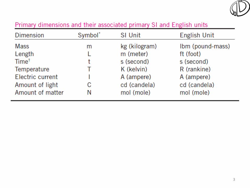
7–1 DIMENSIONS AND UNITS
A dimension is a measure of a physical quantity without numerical values, while a unit is a way to assign a number to the dimension. For example, length is a dimension, but centimeter is a unit.
Dimension: A measure of a physical quantity (without numerical values).
Unit: A way to assign a number to that dimension.
There are seven primary dimensions (also called fundamental or basic dimensions): mass, length, time, temperature, electric current, amount of light, and amount of matter.
All nonprimary dimensions can be formed by some combination of the seven primary dimensions.

4
The water strider is an insect that can walk on water due to surface tension.

5
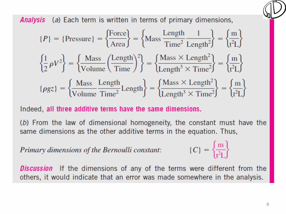
7–2 DIMENSIONAL HOMOGENEITY
You can’t add apples and oranges!
Total energy of a system at state 1 and at state 2.
The law of dimensional homogeneity: Every additive term in an equation must have the same dimensions.

6
An equation that is not dimensionally homogeneous is a sure sign of an error.

7
The Bernoulli equation is a good example of a dimensionally homogeneous equation. All additive terms, including the constant, have the same dimensions, namely that of pressure. In terms of primary dimensions, each term has dimensions {m/(t2L)}.

9
Basics of fluid flow
Types of flow
Fluid Ideal/Real Compressible/Incompressible
Flow Steady/Unsteady Uniform/Non-uniform Laminar/Turbulent Pressure/Gravity (free surface)

10
Basics of fluid flow
One -, two -, and three- dimensional flows
This is the most general 3-D flow:
The flow is classified as 2-D if: The flow can be viewed as 1-D if:

11
Basics of fluid flow
Velocity and Acceleration
This is the most general 3-D flow:
For steady 1-D flow:

12
Basics of fluid flow
Velocity and Acceleration
Convective (spatial)
acceleration
at
Local (temporal)
acceleration
an

13
Basics of fluid flow
Reynolds Transport Theorem & Continuity
QVAVA 2211

14
Energy in Steady Flow
Bernoulli’s Equation
Unit: L
(Energy per unit weight)
Basic assumptions:
•Inviscid & incompressible fluid
•Steady flow
•Applies along a streamline
• No energy added or removed from the fluid along the streamline
Piezometric pressure

15
Energy in Steady Flow, Pipe Flow
V
p/γ p/γ
V2/2g
Bring moving water to a halt, and it'll drive a column of water up to exactly the height from which water would flow to gain that velocity.
Pitot Tube (Measures stagnation pressure)
Free stream dynamic pressure
Free stream static pressure

16
Energy in Steady Flow, Free surface flow
V
V2/2g
Bring moving water to a halt, and it'll drive a column of water up to exactly the height from which water would flow to gain that velocity.
Pitot Tube (Measures stagnation pressure)
17
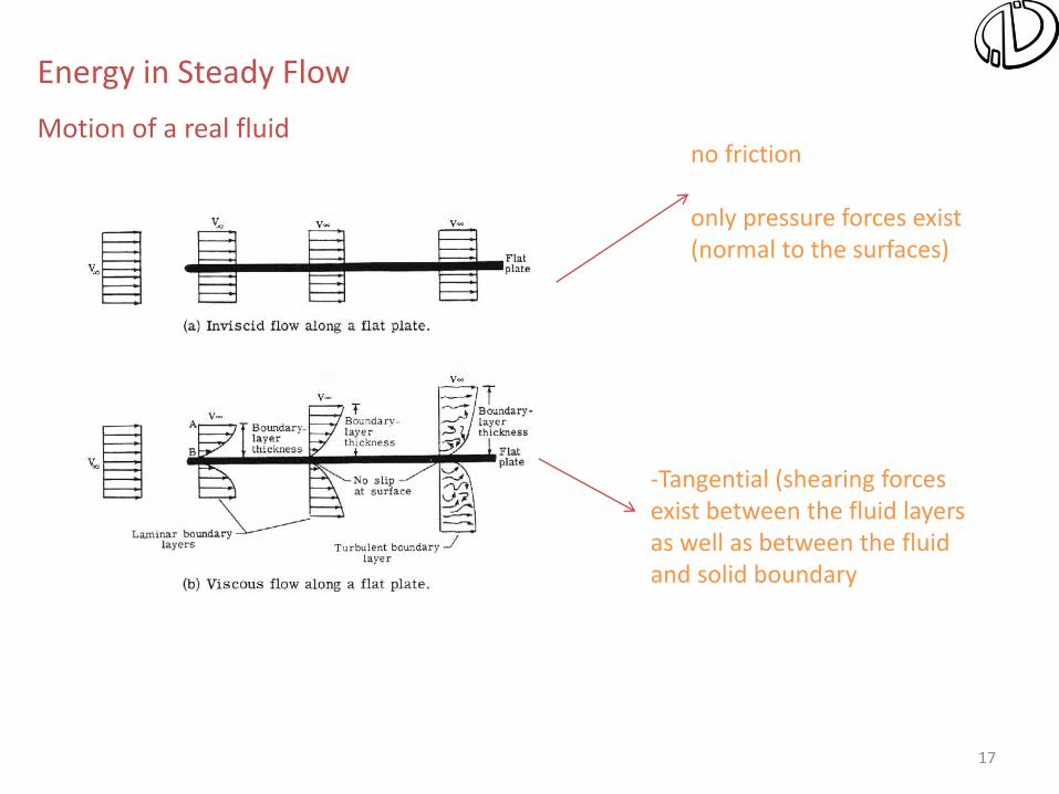
Energy in Steady Flow
Motion of a real fluid no friction only pressure forces exist (normal to the surfaces)
-Tangential (shearing forces exist between the fluid layers as well as between the fluid and solid boundary

18
Energy in Steady Flow
Motion of a real fluid P :perimeter p :pressure

19
Energy in Steady Flow
General Energy Equation, steady flow, incompressible fluid
For an incompressible fluid with γ = const. and α =1:

20
Energy in Steady Flow
General Energy Equation, steady flow, incompressible fluid
For an incompressible fluid with γ = const. and α =1:
If there is no machine between points 1 and 2:
If head loss is neglected:
Real fluid
Ideal fluid

21
Energy in Steady Flow
Definition of Hydraulic Grade Line and Energy Line

22
Energy in Steady Flow
Definition of Hydraulic Grade Line and Energy Line
Real fluid
EL is positioned above the HGL by an amount equal to velocity head (V2/2g)

23
Energy in Steady Flow
Tips for Drawing HGL & EL
1) As the velocity goes to zero, the HGL and the EL approach each other. Thus, in a reservoir, they are identical and lie on the surface.
2) The EL and HGL slope downward in the direction of the flow due to the head loss in the pipe (exceptions: pump, diffuser). For steady flow in a pipe, the slope will be constant (ΔhL/ΔL = const.)
3) A jump occurs in the HGL and the EL whenever energy is added to the fluid as occurs with a pump, and a drop occurs if energy is extracted from the flow, as in the presence of a turbine.

24
5) At points where the HGL passes through the centerline of the pipe, the pressure is zero. If the pipe lies above the HGL, there is a vacuum in the pipe, a potential location for cavitation, also a condition that is often avoided, if possible, in the design of piping systems; an exception would be in the design of a siphon.
4) When a flow passage changes diameter, the distance between the EL and HGL will change, because velocity changes. In addition, for real fluids, the slope of the EL will change because the head loss per length will be larger in a conduit with larger flow velocity.
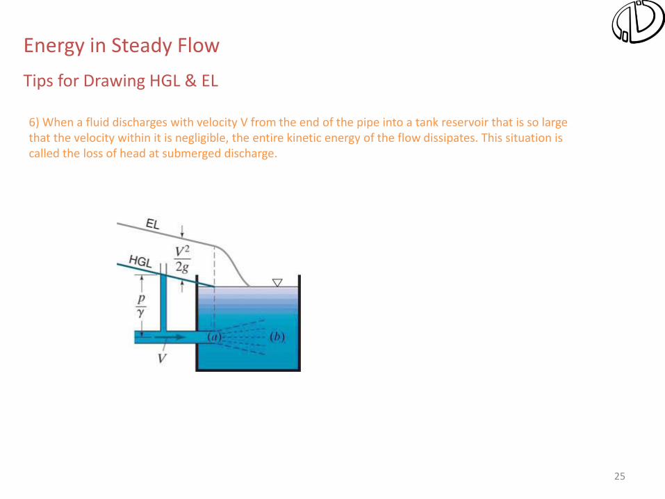
Energy in Steady Flow
Tips for Drawing HGL & EL
25
6) When a fluid discharges with velocity V from the end of the pipe into a tank reservoir that is so large that the velocity within it is negligible, the entire kinetic energy of the flow dissipates. This situation is called the loss of head at submerged discharge.
Energy in Steady Flow
Tips for Drawing HGL & EL

26
8–2 ■ LAMINAR AND TURBULENT FLOWS
Laminar and turbulent flow regimes of candle smoke.
The behavior of colored fluid
injected into the flow in laminar
and turbulent flows in a pipe.
Laminar: Smooth streamlines and highly ordered motion. Turbulent: Velocity fluctuations and highly disordered motion. Transition: The flow fluctuates between laminar and turbulent flows. Most flows encountered in practice are turbulent.
Laminar flow is encountered when highly viscous fluids such as oils flow in small pipes or narrow passages.

27
Reynolds Number
The transition from laminar to turbulent flow depends on the geometry, surface roughness, flow velocity, surface temperature, and type of fluid.
The flow regime depends mainly on the ratio of inertial forces to viscous forces (Reynolds number).
The Reynolds number can be viewed as the ratio of inertial forces to viscous forces acting on a fluid element.
Critical Reynolds number, Recr: The Reynolds number at which the flow becomes turbulent.
The value of the critical Reynolds number is different for different geometries and flow conditions.
At large Reynolds numbers, the inertial forces, which are proportional to the fluid density and the square of the fluid velocity, are large relative to the viscous forces, and thus the viscous forces cannot prevent the random and rapid fluctuations of the fluid (turbulent). At small or moderate Reynolds numbers, the viscous forces are large enough to suppress these fluctuations and to keep the fluid “in line” (laminar).

28
For flow through noncircular
pipes, the Reynolds number
is based on the hydraulic
diameter
For flow in a circular pipe:
The hydraulic diameter Dh = 4Ac/p is defined such that it reduces to ordinary diameter for circular tubes.
In the transitional flow region of 2300 Re 4,000, the flow switches between laminar and turbulent seemingly randomly.
4,000
4,000