insight v4-construction notes- · pdf fileinsight v4 construction notes by: mark hunt ......
TRANSCRIPT
Pg.1
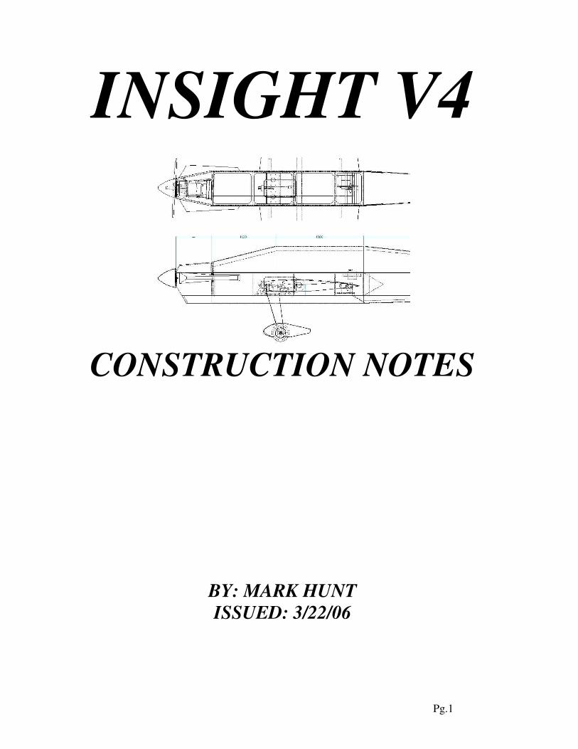
INSIGHT V4
CONSTRUCTION NOTES
BY: MARK HUNT
ISSUED: 3/22/06
Pg.2
INDEX
Title Page 1
Index 2
Introduction 3
Material list 4
Foam Cutting Notes 5
Wing 5
Stab 8
Vertical Fin 8
Fuselage Foam Parts 9
Fuselage –Main 10

Pg.3
INTRODUCTION
I became involved in pattern a few years ago. As my skill level advanced, I realized that to be
competitive in the higher classes, I would need more than an old 60 size Kaos. At the time, I could
not justify the cost of a 2 meter size pattern kit, much less an ARF. Out of necessity then, I began to
design my own pattern plane around the affordable OS 160fx. I called this plane the Insight.
The Insight is now in its Version 4 form. The construction consists of exclusively foam, ply, and
balsa. This produces a very light, strong structure. Also, without any fiberglass or plastic parts
necessary to complete the aircraft, we will likely never have a parts supply issue. The model can be
built and covered completely with a monokote type film or it can be finished with fiberglass and
painted as desired.
The construction of the plane is based on a simple
fuse-box structure. The top and bottom turtle decks
are made of sheeted foam parts and simply added to
the fuse-box structure. The wings and tail section are
also sheeted foam. All of the foam parts can be
sheeted and nearly finished prior to building the fuse-
box. Once, the fuse-box is complete, the construction
then goes very quickly by adding the sheeted foam
components to create the finished assembly.
It is important to note that this aiplane has been built
and flown using many different power plants
(OS140rx, OS160fx, YS140sport, YS140L, YS140DZ)
. To date though, I do not know of any flying with E-
power. With some forethought, this could be easily
accomplished while still making the 11 lb weight limit.
Due to the fact that this is a plan built airplane,
modifications to suit the builders liking are not
difficult, and in fact, they are encouraged. Some have
been finished with nicely rounded corners along the
fuse and a few very nice canopy designs have been
shaped using foam and glass. The idea here is that the
Insight can be personalized without a lot of effort. I
certainly cannot say that some modifications will not
effect flight performance, but to this point, the many
cosmetic changes that I have seen, still produced a fine
flying airplane.
The following building notes are for reference only
and do not necessarily describe the best way to build
the aircraft. I consider myself an experienced builder,
but by no means an expert builder of pattern aircraft.
This reference documents how I built the aircraft with the help of some wonderful r/c pals. If you
Pg.4
are an experienced pattern builder, then I am sure there will be areas that you would prefer to do
another (and much better) way. In my experience, I almost always find a better way the next time.
SPECIFICATIONS:
Span: 74” Engine: 140-160 2c or 4c
Length: 78” Radio: 4 ch.
Area: 890 sq. in. Weight: (prototype) 9lbs. 12oz.
Finish: (prototype) Wings-Monokote, Fuse & Tail – F/G & Paint (PPG)
MATERIAL LIST
Wood:
2 ea. 48”x4”x1/8” balsa sheet med. density
2 ea. 36”x4”x1/8” balsa sheet med. density
1 ea. 36”x6”x1/16” ply 3 ply
2 ea. 36”x12”x1/8” lite ply (templates, formers, etc.)
1 ea. 6”x12”x1/4” ply 5 ply (gear plate)
3 ea. 4”x36”x3/8” balsa low density (LE, TE, caps etc.)
1 ea. 4”x36”x1/4” balsa low density (nose sheeting)
1 ea. ½”x ½”x36” triangle stock
2 ea. ¼”x¼”x36” balsa med. density (DEPS pushrod setup)
35+sheets 1/16”x4”x36” balsa contest grade
Carbon Fiber:
2 ea. 4”x 0.007”x36” (will be cut into 1” wide strips later)
My Misc. List:
8 ea. 4-40 blind nuts (landing gear plate)
8 ea. 4-40 cap screws/lock washers
4 ea. 6-32 blind nuts (mtr. Mount)
6 ea. 6-32 cap screws/lock washers
1 ea. Set of wing adjusters (use two sets if you prefer)
1 ea. PBG 7/8”x30” wing tube & sleeve (aluminum optional)
1 ea. BVM hatch latch (used on my canopy)
1 ea. MK tailwheel (light & durable)
1 ea. Landing gear set (Icepoint or your preference)
1 ea. DEPS (elev. Setup) Central Hobbies type
1 ea. Hyde type Eng. mount
1 ea. Nose Ring
1 ea. 1/8”x36” C.F. Rod (I use for ctrl horns, canopy pins)
1 ea. Elmer’s ProBond or Gorilla (polyurethane glue)
4 ea. Masking tape roll (skins, gluing edge caps, etc.)
1 ea. Double face masking tape (golf grip tape works great for taping foam templates to
foam blanks)
Pg.5
FOAM CUTTING NOTES
Many thanks are in order to an r/c pal, Richard Lewis, who jumped into foam cutting with me. I
don’t think either of us have built a ribbed wing since. If you are not familiar with hot wire cutting,
don’t worry; it is not difficult at all. A little practice with a hot wire cutter is usually all it takes to
get the hang of cutting around templates to create all sorts of shapes. There are several foam cutting
bows and power supplies available via several r/c sources. There are also many foam cutting
services that can provide CNC cut foam parts if supplied with the plans for the templates.
Using foam for all of the turtle decks seems to have several advantages: sound/vibration absorption,
stiffness, uniformity, and simplified construction.
Also, it is best to cut and sheet all of the foam parts prior to building the fusebox. Why? Because,
if there are any discrepancies between the theoretical size of the foam cores and the actual size, the
fusebox width may be adjusted (by resizing the width of the fuse formers) slightly to accommodate
the difference.
WING CONSTRUCTION
Please note: there are many great sources of information available with regards to building foam
core surfaces, such as Terry Brox’s webpage. Below, is simply a collection of notes on how I built
the prototype.
Measure and cut the wing panel planform in the foam block (start with 18”x36”x3”). Cut the
templates for the root and tip from the plans (carefully) and include the tube sleeve hole location in
the root rib template (sand to fit your tube sleeve). Mark both sides of the template with the tick
marks so that either side can be used (you do want a left and right wing right?).
Align and double side tape (don’t use much) the templates to each end of the wing panel blank.
Using a hot wire cutter carefully cut the core. Follow the same procedure to cut the opposite wing
core (use opposite side of tip template when taping to the 2nd
blank).
With the cores placed back into the shucks (taped together), mark the locations on the top AND
bottom of the shuck/core assembly for the wing spar tube and the sub-ribs, etc. (using the plans).
To cut the tube sleeve hole: The tube sleeve hole must be drilled so that it will be parallel with the
TOP surface of the wing core. Once mounted on the airplane, this will give us a bit of dihedral only
in the bottom surface of the wing. Cutout the root rib template and spar tube hole, carefully final
fitting the hole to your wing tube. Double side tape the root rib template onto the core. Setup the
core/shuck assembly upside down on a nice, flat building surface. Using the 7/8” wing tube (not the
sleeve), shim the tube up with scrap wood so that it will lie flat on the table at the necessary height
to enter the hole (centered) in the root template. Align the tube with the marked line on the bottom
surface of your shuck (centerline of the spar tube sleeve location). You should be able to use a
large builder’s square against the spar tube and the root template to make sure the alignment is
correct (if not, double check the layout markings on your shuck). You may want to place some
Pg.6
weight on the shuck and tape the builder’s square in place on your table to help act as a drill guide.
Slowly, drill into the core by hand using the spar tube. A little at time and you will slowly get to the
desired depth (see plans). You can ream the hole out using the tube sleeve so that it is a nice fit.
Perform this same procedure for the other wing core, just make sure you have the core upside down
and root template taped on correctly. This is a great time to measure twice (or 3 or 4X’s) and cut
once. I later built a nice jig to hold the tube square and parallel to a piece of MDF. I cutout wooden
“V” shaped blocks that allow any size tube to ride and rotate while cutting parallel to the table and
square to the wing core.
The slot for the sub-rib can now becut. Hopefully, the line is marked on the top and bottom of your
shucks already. I used the hot wire to cut this by taping a piece of lite ply on top of the shuck/core
assembly with a 1/8” slot (jig saw) cut about 1” past the spar tube location. I taped an identical cut
piece of lite ply on the bottom of the shuck in the same position. I guided the hot wire down one
side of the slot and back up and out along the other side of the slot. This gave me a nice 1/8” wide
slot and a 1/8” thick template for the sub-rib to cut from 1/8” lite ply. This little template reduced
some sanding and fitting time of the sub-rib. The sub should fit snug into the cut slot. Perform the
same procedure for the T.E. sub-rib.
I placed the sub-rib into the core temporarily, then slid the spar tube sleeve in and lightly spun it to
mark the sub-rib (lipstick on the end of the tube works great). I removed the sub-rib and cut the
hole to fit around the spar tube sleeve. Trial fit the sub-rib and tube sleeve in the core with tube
sleeve extending through the sub-rib about ¾”. I glued the sub-rib in place using a small amount of
polyurethane glue. I temporarily inserted the tube sleeve to align the sub-rib correctly. I placed
some wax paper around the area of the sub-rib and placed the core back into the shuck with a bit of
weight on top. After curing, I sanded the sub-rib and any expanded glue flush with the wing cores.
Use masking tape on the surrounding core to protect the foam while sanding the sub-rib.
If desired, the aileron servo extension slot can be cut into the bottom surface of the core before
sheeting. I prefer not to leave any gap or slot that exposes the core surface while sheeting the
wings. Therefore, I cut the hole later (after sheeting) with a sharpened ½” metal tube.
I skinned my wing cores using the following method. There are other methods, including vacuum
bagging (Whatever method is preferred should be used by the builder). Below is my method.
Please note that you will need a very flat, strong building surface to support the weight used on top
of the cores while curing the skins. Typical weight (sand bags) used on top of a wing panel will be
600+ lbs.
Layout 1/16” contest balsa sheets for the wing skins. I re-cut the edges of each sheet with a straight
edge so they would lie together nicely for taping. Tape the sheets together along the edges with
masking tape to make a single sheet larger than the wing planform. Place the shuck/core on the skin
and mark the perimeter with a pen, then cut with a razor blade and straight edge. Make an opposite
skin as well so that you will end up with a top and bottom skin that is taped together.
Prepare two, 1” wide x 34” long strips of c.f. (.007” thick). One will go directly on top of the spar
tube and one directly below as shown on the plans. You may add any other c.f. strips or mat as
desired to strengthen the wing further.
Pg.7
Apply the polyurethane glue to the inside of one skin using your favorite method (4” roller works
great). Apply glue to the c.f. strip and place on the wing skin or core. Then place the skin into the
shuck (bottom) and set the wing core on top. Then quickly get to work on the other skin. Apply
glue and c.f. and place on the core. Place top shuck on, carefully check alignment of the skins
within the core/shuck assembly, then place on a hard, very flat surface with weight
(500+lbs….that’s only about 1 psi across the wing surface) to dry overnight. I use a very strong,
hard, flat counter-top as a base. I use a large sheet of ¾” thick MDF (just a touch bigger than the
wing panel planform) on top of the shuck/core to support several bags of sand (50 lbs. each)
carefully distributed. Let dry overnight.
Remove wing cores. Sand the leading edges and trailing edges smooth. Layout the aileron cutout
lines and cut with sharp razor (may need to do so from top and bottom of wing surface). Sand the
all exposed edges smooth. Using 3/8” thick sheet balsa (light), cut caps for the leading edge and
trailing edge of the wing, leading edge of the aileron, and aileron ends. I used 1/8” balsa to cap the
ends of the aileron and aileron cutout on the wing. I also used 1/8” balsa to cap the wing tip after
cutting wing core to the desired angle as shown on the plans. Use polyurethane glue and masking
tape on all caps and let dry overnight. Sand all edges (round L.E., bevel aileron L.E.) smooth. Sand
the skin flush with the foam core at the root rib carefully.
The root rib may be cut and glued in place as well. Any hard points (stud?) and sleeves for wing
adjusters must be worked out now before gluing the root rib in place. If working to the plan, then
glue the hard balsa block to the backside of the root rib at the front hardpoint location with a ¼-20
nylon, aluminum, or steel bolt threaded and glued into place so that the threaded stud will enter the
fuse where it can be secured with a wing nut. For the aft hard point I added a hard balsa block
behind the root rib where a wing adjuster sleeve will be fitted later. Some foam will have to be
pocketed out at these fore and aft positions to allow the root rib to lie flat on the foam. Double
check the fit of the root rib over the spar tube sleeve (it should be fitted so that it is snug). Glue in
place with polyurethane glue (masking tape to hold in place) and let dry. Afterwards, sand edges
clean and flush with wing skin.
If you prefer, you may cut hinge slots and setup the aileron servo and the aileron control horn hard
point. For the aileron horn hard point, I used a small square (3/4”x3/4”) of 1/16” ply on top and
bottom of the aileron surface. I cutout the top and bottom skin (3/4”x3/4”) at the desired location
and polyurethane glued the ply plates flush in place. Later, I carefully drilled all the way through
the plates and aileron with a 1/8” bit. Layout is crucial to end up with a connection pivot point
directly above the hinge line. I use a length of 1/8” c.f. solid rod as a control horn, glued into the
hard point plates.
The aileron servo cutout should be performed very carefully as not to go through the top wing skin.
Remove the foam and sheet inner walls with 1/16” balsa. I like to surface mount the servo using
1/16” ply in the wing surface (same as aileron hard point).
As a side note, my wing panels came out at 14.5oz. each, with the servo, aileron linkage (4-40), CA
hinges, and covered with monokote. Using contest grade sheeting is imperative for light wings.
Pg.8
STAB CONSTRUCTION
I built my stab as a solid piece without adjusters. I set the stab carefully in the fuse and glued it at -
0.25° (negative) incidence. This may be contrary to many builders’ methods, but this is the method
I prefer for lightness and durability. The stab can easily be built using a stab tube and incidence
adjusters if so desired (I have marked two reference hole locations on the plans if you wish to
mount the stab on a tube with forward incidence adjusters).
Similar to the wing construction, the foam cores should be cut to the planform shape first. Then,
using the root and tip templates, cut the cores. The cores can be sanded lightly, then skinned with
1/16” contest grade balsa. Carbon Fiber may be added to each top and bottom core slightly ahead
of the hinge line in a layout similar to what was done on each wing panel.
After sanding the stab sheeting flush with all foam edges, I joined the two halves using
polyurethane glue. I then cut the elevators and center rudder clearance away from the solid stab. I
sanded all exposed edges and capped with 3/8” contest grade balsa on the hinge line and L.E. The
tips were capped with 1/8” balsa. I used 1/16” ply plates as hard points in each elevator halve
(similar to ailerons). Finally, the center section of the stab was glassed with 3 layers of 0.75oz.
cloth, each layer extending slightly further out (spanwise). This makes a strong joint that is easy to
sand flush with the balsa skin.
VERTICAL FIN
The vertical fin is constructed in similar fashion to the stabs and wing panels. Similar to the wing
construction, the foam core should be cut to the planform shape first. Then, using the root and tip
templates, cut the core. The core can be sanded lightly, then skinned with 1/16” contest grade balsa.
Carbon Fiber may be added under the skin, but I did not feel it was necessary.
After sanding the sheeting flush with all foam edges, I sketched all the cut lines. I then cut the
rudder away and the vertical fin base. Cut the baseline for the vertical fin using a table saw or
hobby jig saw so that the cut surface will be as square as possible to the vertical fin. This surface
will be glued later to the top of the fuse-box. Save the cutaway base section of the fin for use as a
dorsal fin later on the bottom of the fuse-box. Later, once the vertical fin and rudder are in place on
the fuse-box, the rudder will extend about 1” below the bottom of the fuse-box. This will allow for
a small dorsal fin to be fitted in front of the rudder later.
I sanded all exposed edges and capped the L.E. with 3/8” balsa sheet. I used 3/8” balsa stock as the
L.E. for the rudder and for the T.E. of the vertical fin. Leave plenty of extension below the fin,
which will be glued later onto the very end of the fuse-box (see plans). Make sure this extension is
wider than the end of the fuse so that when it is glued in place later, it can be sanded flush with each
of the fuse sides. The top of the fin and rudder were capped with 1/8” balsa, then I added a sheet of
3/8” to the top of the rudder for the counterbalance. I taped the rudder in place with the vertical fin
and sanded the forward part of the counter balance to shape (airfoil).
Once I was sure of the rudder horn location, I used 1/16” ply plates as hard points in each side of
the rudder.

Pg.9
TURTLE DECKS, CANOPY, AND CHEEKS
Layout the proper foam blanks, cut to the correct length and attach the templates to each. Make
sure the templates are lined up correctly with one another at each end of the foam blank. Wire cut
the cores. The cores will require an outside cut and a cut inside of the templates. The turtle deck
cores will essentially be a 3/8” foam layer when you are done. A note about the top-rear turtle deck
core: This piece has a high degree of taper and as a result, the small end (end of the fuse top) will
likely burnout due to the hot wire not moving nearly as fast as the forward end. Not to worry, most
of the rear section of this piece will be cut away to allow the vertical fin to pass through later.
To skin each of the turtle decks (this applies to all decks, including the pieces for the canopy): Tape
some 1/16” sheets together and carefully cut and fit them so that they will lie together nicely inside
the outer shuck. In some cases, I used paper templates to get the right shape before cutting each
piece of taped balsa sheeting. I also found that many times, I needed a scrap piece of 1/16” under
the bottom of the core and its skin to get even pressure distributed on the high angled deck sides.
Once laid into the shuck properly, they are ready for polyurethane glue. Take them back out and
spread the glue sparingly and evenly (same as wing skinning). Assemble the skins into the base
shuck and carefully place the core in and the inside shuck. Then place weight on top (I used one
layer of bricks, lengthwise). If you prefer, you may want to place wax paper into the base shuck
prior to gluing, however, I found it a bit difficult to keep the light 1/16” sheeting (with glue) in
place properly as I was trying to insert the core for curing. If you do not use wax paper, you may
find that the outer shuck will be glued to the core in a couple places where the polyurethane glue
expanded through the corner joints. I also tried using masking tape on the outside of the corners
where each skin meets (top and sides), but again, I was not able to get the sheets to lie down nicely
into the base shuck. After the glue had cured, I had to gently break the sheeted core out of the base
shuck. It was very easy and did not cause any damage to the skinned core. Be sure to save the base
shucks, as it will make a nice cradle for the finished fuse.
Sand the edges of the turtle deck to remove any excess polyurethane glue. If you prefer, bevel the
corners as much as you like and add some balsa to allow for larger rounding of the corners.
For the two canopy sections, you will also have to sheet the base for strength. Use 1/16” contest
grade balsa (cross grain!). I also added a couple 1/16” balsa formers that I hand fitted to the inside
of the straight canopy section for added stiffness. I glued them in with polyurethane glue. I have
since changed the inside shape of the foam template to allow for a thicker foam wall and hence, the
balsa formers will not be needed.
You should end up with 5 separate turtle deck pieces in all (2 bottom, 3 top). Set these aside for
now until the fuse-box is finished.
The same methods above apply for cutting and sheeting the blanks for the cheeks. The core will be
a straight “V” section, which gets sheeted. Keep the sheeted pieces in their shucks for later. The
shucks will be used to hold the cheek square while cutting the top view profile when fitting to the
nose of the fuse.
Pg.10
FUSELAGE
Cut all the forward (straight section) formers as per plan. Be sure to keep all formers the same size
and as square as possible. At this time, cut the landing gear plate and gear plate former (F4) as well,
keeping its width exactly the same as the formers. The firewall outline may be cut as well.
Layout the 1/16” ply fuselage doubler and cut one for each side of the fuse.
Layout the fuse sides (3/16”x4” medium density) with a 48” long piece to the front and a 36” piece
toward the back. Layout a splice (opposite direction on each fuse side) as shown on the plans. The
length of the spliced pieces should be slightly longer than the entire length of the fuse from prop to
vertical fin post. This will allow for some losses in length due to the bending of the fuse sides at the
front of the plane and the long tail taper. Carefully glue the spliced sheets together making sure to
keep the two pieces straight along one edge (I glued up against a long straight edge). Now, with
one edge straight, mark 4” from that edge in several places along its length, and trim to 4” (fuse side
height). Do this for each fuse side so that we will be starting with straight and parallel fuse sides.
Layout the locations for each 1/16” ply fuse doubler, which should start at the firewall location.
Remember to leave some extra length (approx. 6-1/2”) from the start of the doubler to the front of
the balsa fuse side to account for the bending inward and sanding of the fuse sides at the nose.
Addendum: I have since built an Insight using vertical grain 1/16” balsa in place of the 1/16” ply
fuse doubler. This has worked very well and is much easier to apply to the inside of the fuse sides
in the forward doubler area.
At this time add a 1/16” balsa vertical grain doubler to the end of each fuse side in the stab area.
I laid out the landing gear leg cutouts and the stab cutouts. You may prefer to build the Insight with
an adjustable stab. I did not build adjusters into the stab. For the stab cutouts, I drew a horizontal
line (centerline of stab airfoil) measured up from the bottom edge of each fuse side. I used the stab
root template to trace the airfoil for the cutout on the fuse sides. I used an incidence meter (without
the L.E. and T.E. cups) to tape the stab cutout template on the fuse side at –0.2° (approximate).
Cutting out the landing gear slots are a bit of a pain if you did not cut the slots out ahead of time in
the 1/16” doubler….ask me how I know this…??
Next, I setup the fuse sides over the top view of the fuse plan using construction squares to keep the
sides square and vertical over the plans. Carefully set and glue the formers for the straight, forward
section of the fuse. IMPORTANT! Keep these formers square with the fuse sides and square to the
building board (vertical). With the fuse main formers in, keep the fuse pinned to the board and
bring the tail together using the tail-post former. I waited until later to glue the firewall in.
Pin or jig the fuse sides in the aft section to get a straight taper back to the tail-post. Glue in the aft
formers. Lightly block sand the top of the fuse-box if any formers or cross braces are not flush with
the top of the fuse sides.
Sheet the top rear section of the fuse-box using cross grain contest grade 1/16” balsa. Do not sheet
all the way to the tail-post. Stop the sheeting just in front of the stab cutouts to allow access there
for gluing the stab in from the inside of the fuse (makes for a clean, strong glue joint).
Pg.11
Now that the fuse-box has some strength, this is when I chose to glue in the firewall. Cutout and
mark centerlines on the firewall and the mounting hole locations for your preferred engine mount.
If you plan to use the specified 1/8” lite ply firewall material, I will be necessary to use a Hyde-type
mount. If using a more solid type mount, I would recommend a heavier firewall. The offsets on the
plan for the firewall centerlines are based on 2.5-3.0° right and 1° down thrust. I drilled the motor
mount holes slightly oversize and used 1/8” lite ply washers later to hold the blinds in place. This
actually allows a touch of adjustment when mounting the engine later. When the engine was
mounted later, I marked and glued the washer/blind nuts in place on the backside of the firewall.
Glue the firewall in place. If you prefer, you may omit the thrust offsets for the firewall (some fliers
now mix it out using their computer radio). Be sure to glue at the proper thrust angles (use thrust
angle templates for reference) using 30 minute epoxy. Once set, cutout and glue in the horizontal
firewall stiffener (1/8” lite ply) across the back of the firewall. Be sure this stiffener fits very well
to the sides of the fuse and back surface of the firewall, it is critical for strength. I then added ½”x
½” light balsa triangle stock (sand stock to fit since the corner is not 90°) in the corners behind the
firewall, above and below the horizontal ply stiffener.
Test fit the aircraft grade ¼” ply landing gear block in place. For the landing gear, I would
recommend a swept back or straight leg bolly type landing gear. I used a replacement gear from the
Ultra-rc Icepoint ARF. I had to cut the gear in half since it comes as a one piece fixed gear and it
needed to be wider for use in the Insight. After trial fitting the gear block inside the fuse, I setup the
gear on the plate outside of the fuse. Be sure to set the bend of each gear leg outside of the gear
plate by approximately 3/16” to allow the bend to be just outside the fuse side. With the gear legs
carefully clamped in place on the plate, I drilled 3 holes all the way through each gear half and the
ply for a 4-40 size bolt. I removed the clamps and drilled out the holes in the ply plate to accept 4-
40 blind nuts and then inserted them (CA’d). I also took this time to test mount the gear legs to the
plate with 4-40 bolts and lock washers to make sure each gear leg was mounted straight. Any
excess length of 4-40 bolts out the bottom of the blind nuts must be cut off now or they will
puncture the bottom fuse-box sheeting (this is the best time to cut the bolts to length). Remove the
gear legs, and test fit the gear plate inside the fuse. The plate should rest against the back of F-3.
Place F-4 against the rear edge of the gear plate. This should all be done flat against the worktable
(wax paper) in the bottom of the fuse-box with the fuse-box still pinned to the worktable. Epoxy
the gear plate and F-4 in place and let dry (the blind nuts will be resting on the work table, so make
sure they are inserted flat in the bottom surface of the gear plate).
The 1/16” ply top surface (for the straight section of the fuse) can now be glued in place. Cut this
ply as per the plan and take time to get a proper fit along the back of the firewall. This ply should
butt joint up to the rear fuse-box top sheeting done earlier. I would recommend using a very
sparingly applied amount of epoxy to glue this sheet in place. It will tie in all the formers and the
firewall and add strength to the front section of the fuse.
With the completed stab (glassed center too), I was ready to set it in place in the fuse. With the fuse
flat and square on the worktable, gluing the stab in was not difficult. I sanded the cutout as
necessary (trial fitting and measuring the height of each tip from the worktable until it was parallel
across the span). I used an incidence meter to continually check and adjust position for -.2°
(assuming your work table and top of the fuse box is at 0°). I then measured from each leading
edge tip to a centerline on the top of former F-3 to keep the stab hinge line square to the length of
Pg.12
the fuse. After measuring, and measuring, and measuring more, I measured once more and glued
the stab in place. With the sheeting not in place above the stab, it allowed access to make a nice
(small) fillet of epoxy along the inside of the fuse and stab intersection. Recheck all measurements
again before the epoxy cures (use slow set of course…).
I decided that at this time, since I had the work surface cleaned off for measuring and setting the
stab, it would be a good time to cut the holes for the spar sleeve through the fuse sides.
***A note about the spar tube***
On my airplane design, the spar tube will be very close to the final CG. My setup and tube location
are based on the use of a YS140sport for power. Therefore, it may be necessary to modify the
location of the spar tube and gear plate (F-3 former also) to accommodate any type of powerplant
that may be heavier with the complete motor, header, muffler, pipe, etc. You may also choose to
leave as is and change the elevator, rudder servo, and/or battery locations based on the balance
characteristics of your setup. If the power plant will be significantly heavier (overall with pipe etc.)
you may want to consider mounting the servo/s in the tail section or move the spar tube forward.
That being said, use your best judgment based on your knowledge and experience.
***Back to the Spar Tube***
I marked the location of the spar tube hole as per the plans and cut as close to size as possible using
a template and a dremel sanding disc. When measuring to locate the tube hole in terms of distance
from the front of the plane, I used F-3 since the firewall is offset for thrust. Remember, these two
holes are to get the sleeve position close, not perfect. The inner/doubler ply washers will be glued
in place later to hold the sleeve in its final, exact position. After cutting the holes, I inserted the spar
tube sleeve through one fuse side, through the 1/8” lite ply washers (sleeve doublers) and finally,
through the second side of the fuse. Trim the length of the sleeve close to the width or flush with
the sides of the fuse.
I will describe the way in which I fitted the wing tube sleeve through the fuselage. It is not
necessarily the best way (I’m sure of that), but it worked for me: With the tube sleeve holes cut and
the sleeve in place, but not glued, I inserted the spar tube. I measured for parallel to the worktable
(just like the stab). I also used two builders’ squares to keep the tube square to the fuse sides. I tack
glued the spar tube sleeve in place. I performed a sanity check by sliding the wing panels onto the
spar tube to check for proper alignment. I had to use my incidence meter to temporarily tape the
panels at 0°, then I was able to check for parallel and square to the fuse and stab. I also measured
from each wing tip to a centerpoint at the aft end of the fusebox. With every measurement o.k., I
secured the sleeve inside the fuse with epoxy.
Nice work. Have a drink….or whatever relaxes you. You can also check to see if the gear legs go
through the fuse sides and mount as planned with the 4-40 cap screws…hey my fuse is sitting on its
own legs!
***Elevator pushrods***
I chose to flip the fuse over and work on the elevator servo and pushrod setup before sheeting the
bottom of the fuse box. I was confident that I could place the servo in the cabin area and adjust
balance later by moving the battery around. Since the firewall is taller than the rest of the fuse box,
that will have to hang off the edge of the workbench. Because I wanted to mount my elevator servo
on its side in the bottom of the fuse I needed to sheet that area to move forward. I sheeted the
Pg.13
bottom of the fuse with 1/16” cross grain balsa from the firewall to the end of the straight section of
the fuse (F7). I added a lightened sheet of 1/8” lite ply inside on the floor joined at the backside of
F6. I used a standard side mount servo tray and wood screwed the tray and servo down with the
arm centered in the fuse. For my pushrods I used the Dual Elevator Pushrod System from Central
Hobbies. I actually hinged (radio south CA hinges) the elevators with the control horns in place to
mark the exit locations for the carbon fiber pushrods. I used balsa sticks to mount/support the c.f.
pushrod system all the way back to the exit points.
With that completed, I sheeted the bottom rear section of the fuse box with, you guessed it, 1/16”
cross grain balsa.
At this time, you may choose to add some lightening holes to the top and bottom (aft section only)
1/16” sheeting. The weight penalty of not doing so may be negligible.
I sanded all the fuse box edges clean and flush and setup to glue the vertical fin in place. Before
doing so, I traced the outline of the vertical fin base onto the top-aft turtle deck. This cutout will be
necessary later to fit the turtle deck around the vertical fin.
The base cut for the vertical fin should already be cut nice and square (see Vertical Fin section). I
carefully measured and glued the vertical fin with the base against the top sheeting of the fuse box
and it’s tail post against the back of the fuse box using polyurethane glue. Make sure it is square to
the stab and parallel to the centerline of the fuse.
I then fitted the top rear turtle deck by cutting out the aforementioned vertical fin clearance. Start
undersize and sand out the airfoil shaped cutout for a good fit around the vertical fin. If you end up
with small gaps here and there, don’t worry, the polyurethane glue will fill nicely. And, whatever it
doesn’t fill, can be filled later with epoxy and/or lightweight filler. After it was fitted around the
vertical fin, I cut and sanded the deck to final length.
I then began to trial fit the two canopy pieces in the front section of the fuse. I sanded and fitted
until both sections fit nicely together between the firewall and the rear deck. The front face of the
forward canopy piece had to be sanded to match the thrust offset of the firewall. Once completed, I
placed some wax paper on the top of the fuse box and joined the front and aft canopy
sections….more masking tape.
**** You may choose to position the canopy cutout however you prefer, including the attachment
method.
*I know there are better ways to mount the canopy section so you may choose to cutout and mount
the canopy much differently than I; here is how I did it.
I laid out the front canopy cut line and used a razor saw to carefully cut through the forward canopy.
I sanded the cut surfaces flat and used 1/16” ply to face them (the razor took out nearly 1/8” of
material). Before gluing the ply facing onto the front piece (which will become part of the fuse), I
cutout a small amount of the foam where my hatch latch pin would be inserted. I glued a small
balsa block into the cavity behind the ply facing and glued both pieces at the same time with
polyurethane glue. After that was cured, I sanded the edges of the ply facing flush with sides and
glued it (stationary piece) onto the fuse.
Pg.14
Before gluing the ply facing onto the front face of the removable canopy section, I inserted a BVM
hatch latch in the canopy. I glued the latch to a piece of 1/16” ply (don’t glue the spring!). I cut the
1/16” balsa sheeting away to allow the assembly to be glued flush with the top surface of the
canopy. I glued the latch and plate into the canopy using polyurethane glue with a dab of lithium
grease on the latch spring. I later used a bit of filler to tidy up the area where the ply plate met the
surrounding balsa sheeting. I pulled back the latch pin and carefully set the canopy in place on the
fuse. By releasing the pin, it made its own mark into the ply facing on the fuse. I removed the
canopy and drilled a small hole on the indention. I hardened the hole with CA. This hole accepts
the hatch latch metal pin.
At the rear of the canopy: I laid out the rear cut line as shown on the plans. I used the open cut
faces to trace and make 1/16 ply faces. I then glued the aft canopy piece to the fuselage. Before
sanding the foam and gluing on the faces, I carefully set everything together on the fuse with the
1/16 ply pieces in place. I then carefully removed just the 2 ply pieces (careful not to move them
across one another) together and drilled them using a 1/8” bit in three places. One hole centered in
the top section and a hole along each side close to the bottom of the canopy (about 1” above fuse
box). With the holes in place in the mating ply plates, I re-assembled the canopy and plates on the
fuse with short, 1/8” diameter c.f. pins joining the two ply plates. The pins will extend into the edge
of each of the foam sections, but not a big deal. Use these indentations in the foam to glue in small
balsa blocks in both the canopy and the rear fuse deck.
At the rear of the canopy, I glued a short 1/8” c.f. pin into each of the holes on the canopy. I left
about ¼” – ½” of each pin sticking out. With some luck these three pins lined up nicely and fit into
the mating holes in the face of the rear turtle deck.
***F-1***
It was time to pull in fuse sides to nose former F-1 and shape the nose of the aircraft. I mounted the
motor mount and the engine to the firewall and checked for proper position of the thrust washer
against the plans (approximate). Then, I cutout the F-1 mid-section former that is centered on the
engine thrust washer. I used the following method to set this former centered and just behind
(spinner clearance) the thrust washer. Using the templates for the F-1 washer, cut it out using any
scrap lite ply with a center hole that matches the diameter of your engine’s prop shaft. Then cut the
F-1 ring spacer out using the template on the plans. This ring should be cut from 1/8 lite ply also
(this will be the clearance between the spinner and nose of the plane). Glue the ring (centered) to
the washer. Now, tack glue the ring to the front face of F-1 (centered as possible). With these three
pieces glued together, place it onto the prop shaft and screw it in place using an old wood prop (or
wood bushing) and the prop nut. Now, the F-1 is in place, centered on the front of the engine with
the matching thrust offset built into F-1.
Pg.15
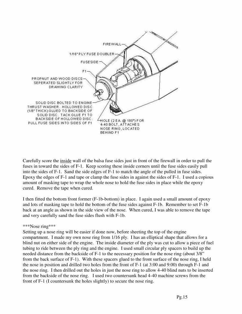
Carefully score the inside wall of the balsa fuse sides just in front of the firewall in order to pull the
fuses in toward the sides of F-1. Keep scoring these inside corners until the fuse sides easily pull
into the sides of F-1. Sand the side edges of F-1 to match the angle of the pulled in fuse sides.
Epoxy the edges of F-1 and tape or clamp the fuse sides in against the sides of F-1. I used a copious
amount of masking tape to wrap the whole nose to hold the fuse sides in place while the epoxy
cured. Remove the tape when cured.
I then fitted the bottom front former (F-1b-bottom) in place. I again used a small amount of epoxy
and lots of masking tape to hold the bottom of the fuse sides against F-1b. Remember to set F-1b
back at an angle as shown in the side view of the nose. When cured, I was able to remove the tape
and very carefully sand the fuse sides flush with F-1b.
***Nose ring***
Setting up a nose ring will be easier if done now, before sheeting the top of the engine
compartment. I made my own nose ring from 1/16 ply. I has an elliptical shape that allows for a
blind nut on either side of the engine. The inside diameter of the ply was cut to allow a piece of fuel
tubing to ride between the ply ring and the engine. I used small circular ply spacers to build up the
needed distance from the backside of F-1 to the necessary position for the nose ring (about 3/8”
from the back surface of F-1). With these spacers glued to the front surface of the nose ring, I held
the nose in position and drilled two holes from the front of F-1 (at 3:00 and 9:00) through F-1 and
the nose ring. I then drilled out the holes in just the nose ring to allow 4-40 blind nuts to be inserted
from the backside of the nose ring. I used two countersunk head 4-40 machine screws from the
front of F-1 (I countersunk the holes slightly) to secure the nose ring.

Pg.16
***For the top of the nose section***
I used two small balsa blocks to make angle brackets for the top section of the front former (F-1t).
These provided some gluing surface and the correct set back angle for F-1t. I glued these to the
back of F-1 with CA. I then glued F-1t in place against the brackets using CA. (Epoxy will be
added later when fuel proofing the engine compartment.)
I carefully sheeted across the tops of F-1t and F2 using whatever sheet thickness necessary (1/4”) to
make the fit flush to the to surface of the canopy section. After cured, I was able to carefully sand
the side angles into the top and side sheets. This allowed me to sheet the sides of the top part of the
nose from F-1t back to F-2. To get the sheeting to meet up nice and flush with the forward section
of the canopy area, it required some filler in places.
With all of this work complete on the nose, it can be final sanded on the corners and flush to the
three F-1 formers.
***Cheeks***
Using the top view of the fuse, I cut paper cheeks that I used to get the correct angle for mating to
the side of the fuse. With the paper templates fitted just right, I used them to cut the sheeted cheek
cores with my jig saw. I left the sheeted cheeks in the shucks and taped the paper template to the
top. Then I just ran it carefully through the saw. This kept the saw cut perpendicular to the cheek
and mated well to the side of the fuse. Don’t forget to cut the facing angles on the front and back
ends of the sheeted cheek core as well. Once they are fitted and ready to glue to the fuse, use
polyurethane glue to cap the front and back edges of the cheeks with 1/16” balsa. Sand the caps
flush, and glue the cheeks to the sides of the fuse with polyurethane glue. You may want to
consider waiting to the glue the cheeks to the fuse later if you are planning to glass the fuse. I chose
to glue them and add small fillets where they met the fuse, using lightweight filler, but glassing the
area was difficult…thank god I had help here. I was very lucky to have my good friend Jim
Sheffield offer to do the entire glassing of the fuse. Now he has a caller forever.
***Back to the bottom of the fuse***
The bottom rear fuse deck can be fitted and glued to the bottom of the fuse box. I trial fitted the
forward bottom deck and trimmed and sanded to create a good fit against the rear deck and a flush
fit with the backside of the firewall. I marked and cut the center section of the deck out to create the
pipe tunnel. I capped these surfaces and the front edges with 1/16” balsa (masking tape to hold in
place). Next, I cut an entry bevel into each of the two pieces to create a smoother entry into the pipe
tunnel from the firewall. These two pieces can then be glued in place on the bottom of the fuse box.
At the aft end of the pipe tunnel, the front end of the bottom rear turtle deck will be exposed. I used
a piece of scrap balsa sheet to make a sort of exit ramp for the rear of the pipe tunnel that met up
with the bottom rear turtle deck. You will have to add a hard point somewhere along the tunnel
(inside the fuse?) for mounting your pipe.
I sheeted the bottom sides of the engine compartment with scrap balsa sheet.
The engine compartment and pipe tunnel can be fuel proofed (I used thinned z-poxy) with your
favorite “get high” resin.
Pg.17
I added a scrap piece from the base of the sheeted vertical fin to make a small dorsal fin that would
match up with the base of the rudder. I glued this on with polyurethane glue. I sheeted the front of
the dorsal with 1/16” balsa and added a 1/16” ply plate at the rear of the dorsal, which was just large
enough to accommodate an MK tailwheel.
***Finishing Details***
Sand and fill to your heart’s content…or your family’s limit on sawdust. Then finish the fuse with
glass/paint or monokote. Mount your remaining radio equipment to your preference. I mounted my
rudder servo as shown in the plans with pull/pull cables midway up on the rudder. I soft mounted
the receiver and battery pack with Velcro and packing foam. I mounted the fuel tank with Velcro
directly in front of the wing tube. If you mount your tank here, you will see it is necessary to
remove the tank every session to easily access the wing nuts for the wing panels.
My control throws are setup up for precision flying. My high rates were adjusted to my liking for
good snaps and spins. The following rates are therefore, simply a starting point.
Low Rates:
Elevator: +/- 5/8”
Ailerons: +/- 5/8”
Rudder: +/- 3”
High Rates:
Elevator: +/- 7/8”
Ailerons: +/- 7/8”
Rudder: +/- 3”
I started with the CG at the back surface of the wing tube, which turned out to be a bit too far aft
and sensitive in pitch. I now have the CG located at the center of the wing tube. I have had it as far
forward as the front of the wing tube as well. To date, nearly every Insight that has flown has
required a few % of up elevator mixed with rudder to make knife edge flight nice and straight.
Good luck with your Insight!