installation & user guide for the biorock systems: …
TRANSCRIPT

PAGE 1 / 55 Installation and User guide – ECOROCK - Systems – 06-12-2016
INSTALLATION & USER GUIDE FOR THE
BIOROCK SYSTEMS:
ECOROCK-1500 ECOROCK-2000 ECOROCK-3000

PAGE 2 / 55 Installation and User guide – ECOROCK - Systems – 06-12-2016
TABLE OF CONTENTS
A. INSTALLATION GUIDE ............................. 5 B. USER GUIDE ........................................... 27 C. APPENDICES .......................................... 38

PAGE 3 / 55 Installation and User guide – ECOROCK - Systems – 06-12-2016
Dear Customer, Congratulations on your purchase of this BIOROCK® Domestic Sewage Treatment Plant. Your new BIOROCK will guarantee years of trouble-free operation, peace of mind and protection for the environment. We highly recommend that you familiarize yourself with this guide for the installation, commissioning and maintenance of your new BIOROCK system. The instructions for the maintenance and visual checks of the system will ensure that you have a reliable and long-lasting sewage treatment plant. Please do not hesitate to contact your BIOROCK distributor for any queries or further assistance. Thank you for choosing BIOROCK.
The installation and commissioning of your BIOROCK® system should be carried out by a BIOROCK trained and approved installer. Your installer will be able to offer you a maintenance contract. The BIOROCK Warranty is only valid if the required maintenance is carried out by a BIOROCK trained and approved installer. Should you not wish to take out a maintenance contract, make sure you have your sewage treatment plant inspected and maintained on a regular basis by an industry trained, competent wastewater professional.
BIOROCK S.à.r.l. 4-5 ZAE le Triangle Vert L-5691 Ellange Luxemburg E-mail: [email protected] Telephone: +352-26-17 66 33
Distributor’s name: Contact person: Address: E-mail: Telephone:
READ CAREFULLY
A. INSTALLATION GUIDE
PAGE 4 / 55 Installation and User guide – ECOROCK - Systems – 06-12-2016

A. INSTALLATION GUIDE
PAGE 5 / 55 Installation and User guide – ECOROCK - Systems – 06-12-2016
A. INSTALLATION GUIDE
ECOROCK SYSTEMS

A. INSTALLATION GUIDE – TABLE OF CONTENTS
PAGE 6 / 55 Installation and User guide – ECOROCK - Systems – 06-12-2016
TABLE OF CONTENTS 1. THE ECOROCK SEWAGE TREATMENT SYSTEM ..................................................................... 7
1.1. General points .............................................................................................................................. 7 1.2. Sizing ............................................................................................................................................. 7 1.3. Precautions ................................................................................................................................... 7 1.4. Identification ................................................................................................................................. 9 1.5. Handling and transport ................................................................................................................. 9
2. OPERATING PRINCIPLES OF THE ECOROCK SEWAGE TREATMENT PLANT .......................... 10 2.1. Primary Tank – Operating principle ............................................................................................. 10 2.2. ECOROCK Treatment Unit – Operating principle ......................................................................... 12 2.3. ECOROCK Treatment Unit – Technical ......................................................................................... 12
3. INSTALLATION LAYOUTS .................................................................................................. 13 3.1 Installation layout n°1.: Gravity discharge (non-electric) ........................................................... 13 3.2 Installation layout n°2.: Pumped discharge (pump after PT) ..................................................... 13 3.3 Installation layout n°3.: Pumped discharge (pump after ECOROCK unit) .................................. 13
4. INSTALLATION OF THE TANKS ......................................................................................... 14 4.1 Principles and constraints of installation works .......................................................................... 14
4.1.1 Before installation of the complete system .................................................................. 15 4.1.2 Installation of the Primary Tank .................................................................................. 15 4.1.3 Installation of the ECOROCK treatment unit ............................................................... 16
4.2 Installation in dry ground conditions .......................................................................................... 16
4.2.1 Installation and digging in dry ground conditions........................................................ 16 4.2.2 Installation of the Tanks in dry ground conditions ....................................................... 17 4.2.3 Backfilling in dry ground conditions ............................................................................. 17
4.3 Installation in wet ground conditions .......................................................................................... 17 4.4 Installation in specific sites .......................................................................................................... 19
4.4.1 Installation in difficult areas and sites ......................................................................... 19 4.4.2 Installation in difficult ground conditions .................................................................... 19 4.4.3 Backfilling in difficult sites ............................................................................................ 19
4.5 Installations under roads, courtyards or storage areas ............................................................... 20 4.6 Other specific cases ..................................................................................................................... 20
4.6.1 Incline too steep ........................................................................................................... 20
5. VENTILATION AND WATER DISTRIBUTION ....................................................................... 21 5.1 Ventilation of the Primary Tank ................................................................................................... 21 5.2 Ventilation of the ECOROCK treatment unit ............................................................................... 22 5.3 Water distribution ....................................................................................................................... 22 5.4 BIOROCK® media ......................................................................................................................... 23 5.5 Securing the lids ........................................................................................................................... 23
6. STOPPING AND RESTARTING THE SYSTEM ....................................................................... 24
7. CONFORMITY AND WORK COMPLETION ......................................................................... 24
8. RECOMMENDATIONS OF USE AND MAINTENANCE ......................................................... 24
9. COMPLIANCE WITH REGULATIONS AND STANDARDS ....................................................... 24
10. WARRANTY ................................................................................................................... 25
A. INSTALLATION GUIDE 1. THE ECOROCK TREATMENT PLANTS
PAGE 7 / 55 Installation and User guide – ECOROCK - Systems – 06-12-2016
1. THE ECOROCK SEWAGE TREATMENT PLANT
1.1 GENERAL POINTS
The ECOROCK Systems from BIOROCK are compact non-electric Sewage Treatment Plants. The treatment relies on the revolutionary BIOROCK biological purification process. The ECOROCK sewage treatment unit is exclusively designed for domestic waste water purification. The BIOROCK plant consists of a Primary Tank and an ECOROCK Bioreactor. Both parts (Primary Tank and Bioreactor) must be ventilated. A small pump can be installed in a pump shaft downstream of the system to lift the treated water and discharge to a higher level if needed.
BIOROCK recommends the installation of an effluent sampling at the outlet of the treatment unit.
The ECOROCK treatment unit can be installed (retrofitted) after a non-BIOROCK Primary Tank, provided that this tank is properly sized, equipped with an efficient effluent filter and properly vented.
1.2 SIZING
The ECOROCK units have a capacity of 6*, 10*, 15* and 30* P.E. (Person Equivalent). This manual is for the ECOROCK-1500, 2000 & 3000. The capacity of the individual ECOROCK unit can be increased if the required final effluent quality is of a lower standard than the results, achieved during the EN-12566-3 Performance test.
* Based 150 l.p.e.day
1.3 PRECAUTIONS
Please note that BIOROCK shall not be responsible for any installation design parameters and groundworks at any case. We recommend to involve a civil engineer or a specialized design office in the design of the system installation if necessary and to follow best practices of the industry. Important precautions for the proper use of the BIOROCK system: Only domestic sewage should enter the system; no rainwater is allowed. To ensure the good working order of the BIOROCK system, the use of automatic toilet cleaners, electric waste-disposal systems and pumps equipped with blades are not to be used. If there is a professional kitchen on site, an efficient and properly sized grease trap should be installed. The grease trap should be installed before the primary tank.
Do not dispose of the following items to the BIOROCK system: Kitchen or motor oils, fats, wax, resin, paint, solvents, hydrocarbon-based products (petrol, crude oil etc.), any pesticide or antibacterial product, items of a toxic nature, boiler or air-conditioning condensate, swimming pool backwash, rainwater, drainage water or ground-water. An effective effluent filter should be installed in the outlet of the Primary Tank, before the water goes on to the Bioreactor.
We recommend that pipework after the ECOROCK unit should allow sampling.
Special care should be taken with the aeration of the system. The aeration should be checked by the installer using a smoke test once pipework and ventilation ducts have been connected and before backfilling the system. The smoke test should be performed under normal representative conditions.
A. INSTALLATION GUIDE 1. THE ECOROCK TREATMENT PLANTS
PAGE 8 / 55 Installation and User guide – ECOROCK - Systems – 06-12-2016
Each system should be vented independently and equipped with its own ventilator (wind driven or electrical). The number of elbows used in the pipework should be limited as much as possible. 90o elbows should not be used, 45o elbows should be used instead. The high air outlets should be installed as close as possible to the low air inlets. Achieving efficient ventilation is the responsibility of the installer as he is familiar with the implementation, site and local conditions that may interfere in the system’s venting. The Primary Tank should be aerated separately in accordance with the manufacturer's instructions.
A. INSTALLATION GUIDE 1. THE ECOROCK TREATMENT PLANTS
PAGE 9 / 55 Installation and User guide – ECOROCK - Systems – 06-12-2016
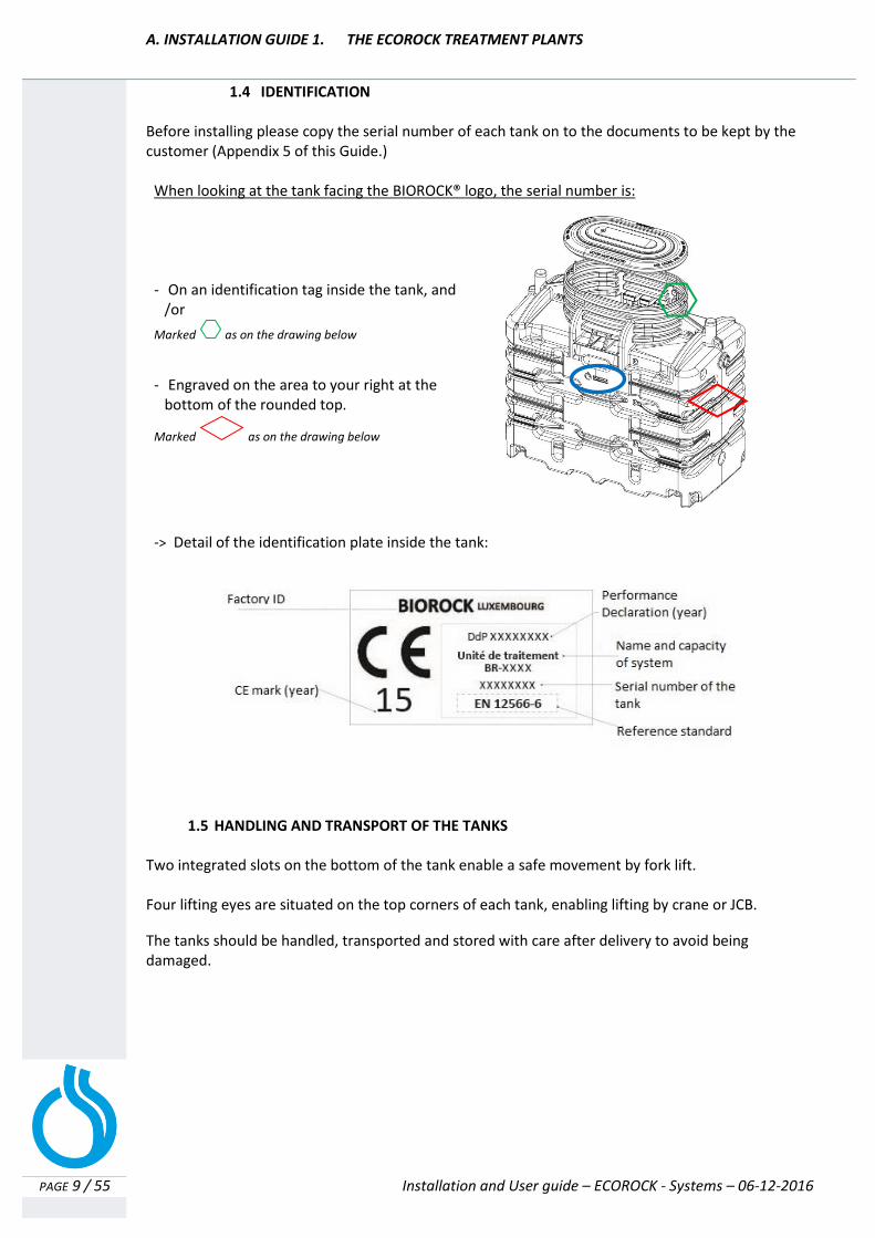
1.4 IDENTIFICATION
Before installing please copy the serial number of each tank on to the documents to be kept by the customer (Appendix 5 of this Guide.)
1.5 HANDLING AND TRANSPORT OF THE TANKS
Two integrated slots on the bottom of the tank enable a safe movement by fork lift. Four lifting eyes are situated on the top corners of each tank, enabling lifting by crane or JCB.
The tanks should be handled, transported and stored with care after delivery to avoid being damaged.
When looking at the tank facing the BIOROCK® logo, the serial number is:
- On an identification tag inside the tank, and /or
Marked as on the drawing below
- Engraved on the area to your right at the bottom of the rounded top.
Marked as on the drawing below
-> Detail of the identification plate inside the tank:

A. INSTALLATION GUIDE 2. OPERATING PRINCIPLE OF ECOROCK UNITS
PAGE 10 / 55 Installation and User guide – ECOROCK - Systems – 06-12-2016
2. Operating principle of an ECOROCK Sewage Treatment Plant
A BIOROCK system is composed of a Primary tank and an ECOROCK treatment unit. Initially the raw sewage enters the primary tank to provide separation and the breakdown of organic solids (Primary Treatment). The sewage then passes through an effluent filter before discharging into the ECOROCK Treatment Unit which incorporates the well proven aerobic digestion process (Secondary Treatment) and filtration process (Tertiary Treatment).
2.1 THE PRIMARY TANK
The effluent (domestic wastewater composed of black water: origin toilets – and grey water: origin kitchen, bathroom, laundry) enters the primary tank. This Primary Tank carries out the first basic phase of wastewater treatment, that is separation of solids and fats by flotation (formation of a grease layer) and by clarification (the suspended solids sink to the bottom of the tank by natural settlement). Separated solids building up at the bottom of the primary compartment are called “primary sludge”. This sludge breaks down in time by anaerobic digestion. The primary tank should always be equipped with an efficient effluent filter. This filter holds back remaining suspended solids, fats and other floating matter which enables a higher quality of pre-treatment.
2.1.1 Ventilation of the Primary Tank
Any Primary tank should have a proper unencumbered low level and high level vent. The low level vent should be connected directly on the outlet side of the tank and the high level on the inlet side and should not be positioned more than 10 m1 from the tank and at a minimum height of 4 m1 with a wind driven ventilator also fitted. The water inlet should be made air tight. All ventilation should be checked with a smoke test.
2.1.2 Performance of the Primary Tanks (PT)
If the Primary Tank being used is not a BIOROCK tank, make sure that the quality of the effluent from the PT meets the BIOROCK requirements. Proper ventilation of a PT is necessary, not only to avoid smell problems, but also to evacuate the gasses produced. A Primary Tank generates malodorous gases like hydrogen sulphide (H2S). Ventilation of the gasses is necessary to prevent H2S being transformed into harmful sulphuric acid (H2SO4). Sulphuric acid will harm the biological process and can cause degradation of the BIOROCK Media.
BIOROCK requires the following performance of a PT in front of the BIOROCK unit:
Composition of normal domestic wastewater (according to EN12566-3+A2 Annex B.3.2): Variation BOD5*
1: 150 - 500 mg O2/l COD*1: 300 – 1000 mg/l S.S.: 200 - 700 mg/l KN: 25 - 100 mg/l NH4-N: 22 - 80 mg/l P-Total: 5 - 20 mg/l *1: The ration between BOD5 and COD should always be < 2

A. INSTALLATION GUIDE 2. OPERATING PRINCIPLE OF ECOROCK UNITS
PAGE 11 / 55 Installation and User guide – ECOROCK - Systems – 06-12-2016
Minimum performance requirements of a Primary Tank*2: Effluent PT Average EN 12566-6: 2008 BOD5: 100 - 350 mg O2/l 200 ± 50 mg O2/l COD: 200 - 600 mg/l S.S.: 40 - 150 mg/l 80 ± 20 mg/l KN: 35 - 100 mg/l NH4-N: 30 - 80 mg/l P-Total: 4 - 20 mg/l *2: The sampling should be done with a minimum 24 hour sampling
The effluent is easy biodegradable if the ratio of BOD5 and COD is less than 2. Between 2 and 3 it is partially biodegradable and greater than 3, the effluent is not biodegradable.
A. INSTALLATION GUIDE 2. OPERATING PRINCIPLE OF ECOROCK UNITS
PAGE 12 / 55 Installation and User guide – ECOROCK - Systems – 06-12-2016
2.2 THE ECOROCK TREATMENT UNIT (Bioreactor) The ECOROCK sewage treatment units are biological purification systems, using the BIOROCK media as a carrier material for bacteria. The ECOROCK unit consists of two biological filtration stages and one aeration stage, has pre-treated water passed through it by gravity. The pre-treated water is spread over the surface of the first layer of BIOROCK media by a distribution system and penetrates into the media for purification. The treated water discharging from the unit must flow by gravity to the next stage or a discharge point.
2.3 ECOROCK TREATMENT UNIT – TECHNICAL
The tanks and covers are made of polyethylene
Each tank has two lifting eyes that are situated at the middle of the tank
The water inlet has a ø of 110 mm
Air inlet and air outlet have a ø of 110 mm
The water outlet has two possible diameters; ø75 and ø 110 mm
Each unit has a serial number that is located on the right side of the tank (A/Chapter 1.3)
All materials in the BIOROCK plants are resistant to corrosion and guarantee a long-term lifespan
The tanks are made by rotational molding in HDPE (High Density Polyethylene)
The tanks are UV resistant and have a lifespan of at least 25 years
The HDPE tanks are 100% recyclable
The screws are made of stainless steel
The pipes are made of PVC and Polypropylene
The entire system is nearly 100% recyclable

A. INSTALLATION GUIDE > 3. INSTALLATION LAYOUTS
PAGE 13 / 55 Installation and User guide – ECOROCK - Systems – 06-12-2016
3. Installation layouts
The installation of the BIOROCK system depends on the available site, gradient, type of ground, the level of the water inlet and the discharge options. When the outlet for final effluent is not accessible, a sampling shaft should be installed. When using a final effluent pump the pump shaft can be used as a sampling shaft.
3.1 INSTALLATION LAYOUT N°1
GRAVITY DISCHARGE (non-electric)
3.2 INSTALLATION LAYOUT N°2
PUMPED DISCHARGE, PUMP AFTER THE PRIMARY TANK
3.3 INSTALLATION LAYOUT N°3 PUMPED DISCHARGE, PUMP AFTER THE ECOROCK® TREATMENT UNIT
PRIMARY TANK ECOROCK
TREATMENT UNIT
OPTIONAL
SAMPLING PIPE DISCHARGE
PRIMARY TANK
INTERMEDIATE PUMPING WELL
ECOROCK
TREATMENT UNIT
OPTIONAL
SAMPLING PIPE
DISCHARGE
PRIMARY TANK ECOROCK
TREATMENT UNIT
PUMPING & SAMPLING PIPE
DISCHARGE
A. INSTALLATION GUIDE 4. INSTALLATION OF THE TANKS
PAGE 14 / 55 Installation and User guide – ECOROCK - Systems – 06-12-2016
4. INSTALLATION OF THE TANKS
This chapter provides a guide to the installation and commissioning of the BIOROCK system. This manual cannot be a substitute for documentation and instructions from manufacturers of non- BIOROCK products integrated into the system by the user.
Please take photographs of each stage of the installation with particular attention to all of the connecting pipework
DO NOT completely fill the tanks with water before unit is backfilled DO NOT use dirty or contaminated water
DO NOT use a mechanical compactor, only compact manually
DO NOT reuse the excavated soil or spoil from the site
DO NOT install the system too close to the house or other buildings DO NOT install the system too close to large trees
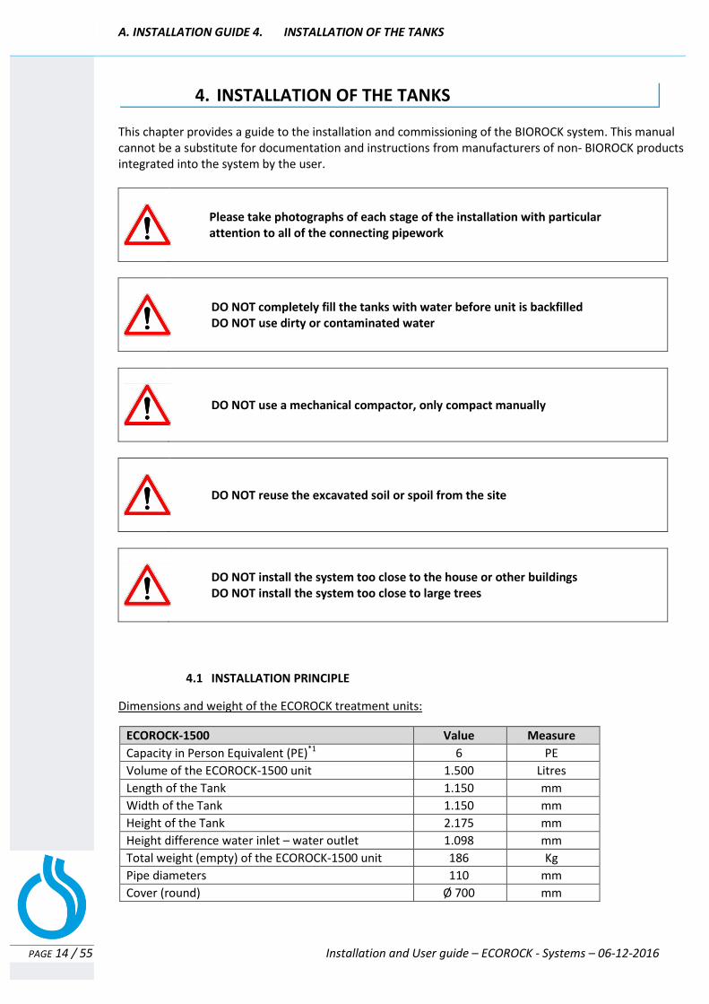
4.1 INSTALLATION PRINCIPLE
Dimensions and weight of the ECOROCK treatment units:
ECOROCK-1500 Value Measure
Capacity in Person Equivalent (PE)*1 6 PE
Volume of the ECOROCK-1500 unit 1.500 Litres
Length of the Tank 1.150 mm
Width of the Tank 1.150 mm
Height of the Tank 2.175 mm
Height difference water inlet – water outlet 1.098 mm
Total weight (empty) of the ECOROCK-1500 unit 186 Kg
Pipe diameters 110 mm
Cover (round) Ø 700 mm
A. INSTALLATION GUIDE 4. INSTALLATION OF THE TANKS
PAGE 15 / 55 Installation and User guide – ECOROCK - Systems – 06-12-2016
*1
The ca
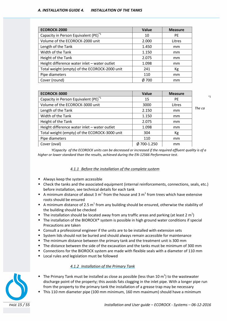
YCapacity of the ECOROCK units can be decreased or increased if the required effluent quality is of a higher or lower standard than the results, achieved during the EN-12566 Performance test.
4.1.1 Before the installation of the complete system
Always keep the system accessible Check the tanks and the associated equipment (internal reinforcements, connections, seals, etc.) before installation, see technical details for each tank A minimum distance of about 3 m1 from the house and 3 m1 from trees which have extensive roots should be ensured A minimum distance of 2.5 m1 from any building should be ensured, otherwise the stability of the building should be checked The installation should be located away from any traffic areas and parking (at least 2 m1) The installation of the BIOROCK® system is possible in high ground water conditions if special Precautions are taken Consult a professional engineer if the units are to be installed with extension sets System lids should not be buried and should always remain accessible for maintenance The minimum distance between the primary tank and the treatment unit is 300 mm The distance between the side of the excavation and the tanks must be minimum of 300 mm Connections for the BIOROCK system are made with flexible seals with a diameter of 110 mm Local rules and legislation must be followed
4.1.2 Installation of the Primary Tank
The Primary Tank must be installed as close as possible (less than 10 m1) to the wastewater discharge point of the property; this avoids fats clogging in the inlet pipe. With a longer pipe run from the property to the primary tank the installation of a grease trap may be necessary This 110 mm diameter pipe (100 mm minimum, 160 mm maximum) should have a minimum
ECOROCK-2000 Value Measure
Capacity in Person Equivalent (PE)*1 10 PE
Volume of the ECOROCK-2000 unit 2.000 Litres
Length of the Tank 1.450 mm
Width of the Tank 1.150 mm
Height of the Tank 2.075 mm
Height difference water inlet – water outlet 1.098 mm
Total weight (empty) of the ECOROCK-2000 unit 241 Kg
Pipe diameters 110 mm
Cover (round) Ø 700 mm
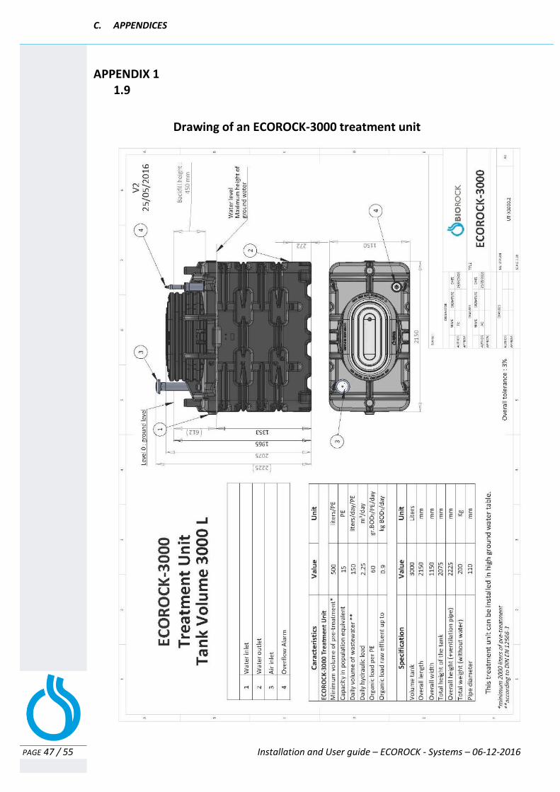
ECOROCK-3000 Value Measure
Capacity in Person Equivalent (PE)*1 15 PE
Volume of the ECOROCK-3000 unit 3000 Litres
Length of the Tank 2.150 mm
Width of the Tank 1.150 mm
Height of the Tank 2.075 mm
Height difference water inlet – water outlet 1.098 mm
Total weight (empty) of the ECOROCK-3000 unit 304 Kg
Pipe diameters 110 mm
Cover (oval) Ø 700-1.250 mm

A. INSTALLATION GUIDE 4. INSTALLATION OF THE TANKS
PAGE 16 / 55 Installation and User guide – ECOROCK - Systems – 06-12-2016
gradient of 2 % and a maximum of 4% The Primary Tank should always discharge by gravity into the BIOROCK system Install the Primary Tank allowing a gradient towards the BIOROCK system The Primary Tank should be installed away from any traffic area, unless special precautions are in place
The Primary Tank must be equipped with an efficient Effluent Filter
Installation of a Pump Well
If the effluent can’t be discharged by gravity, install a pump well & pump. The pump is required to lift the effluent (purified water) to a higher level. BIOROCK has developed an optional PE pump well with a diameter of 400 mm. The PE pump well has the same height as the ECOROCK unit. All the connections are matching with the openings at the ECOROCK units. At the end of the BIOROCK Reactor the purified waste water (effluent) is collected in the pump shaft and can be easily pumped to a higher level with a normal submersible pump.
The seals on the BIOROCK tanks are flexible and have a diameter of 110 mm The discharge pipe for the treated effluent should have a minimum gradient of 1%
4.1.3 Installation of the BIOROCK treatment unit The BIOROCK unit must be installed downstream of the Primary Tank The effluent from the Primary Tank should flow by gravity to the BIOROCK unit The gradient of the treated effluent pipe to the BIOROCK unit should be a minimum of 1%
4.2 INSTALLATION IN DRY GROUND CONDITIONS See Appendix «Installation in dry ground conditions»
Conditions for installation:
- Dry and stable ground conditions - Absence of water at the bottom of the excavation
4.2.1 Installation and digging in dry ground conditions The maximum level of top soil above the backfill is 200 mm The units must stand on a clean and stable base such as concrete In dry ground conditions pea gravel can be used Mud and other soft materials must be removed from the bottom of the excavation prior to installation A stable base must be created at the bottom of the excavation The base of the excavation should be level and compacted There must be a distance of at least 300 mm between the walls of the excavation and the

A. INSTALLATION GUIDE 4. INSTALLATION OF THE TANKS
PAGE 17 / 55 Installation and User guide – ECOROCK - Systems – 06-12-2016
units
4.2.2 Installation of the tanks in dry ground conditions Once the base of the excavation is stable, the installation can begin The Primary Tank should not be positioned horizontally; it must have a slight gradient towards the water outlet Before connecting any water or ventilation pipes, ensure that the units are perfectly installed Ensure that all levels are correct so that the wastewater can flow freely through the system Check that all connections are correctly positioned Ensure that the seals are watertight
4.2.3 Backfilling in dry ground conditions Backfill the hole with 3 to 6 mm smooth pea gravel, or lean-mix concrete whilst filling the tanks with water at the same level Do not exceed 300 mm per filling and compaction cycle Make sure that the BIOROCK® media is completely saturated with water Do not backfill with the soil removed during the excavation: roots and stones can damage the tank. Do not compact the backfill material mechanically: compact manually. Backfilling around and filling both the Primary Tank and BIOROCK unit with water should take place at the same time. Once the backfilling is finished and compacted, check the levels of the tanks again The lids or access covers of the system should be installed just above ground, level to provide easy access for maintenance. Close and secure all covers with screws Complete the backfilling once all pipework has been checked and connected.
4.3 INSTALLATION IN HIGH GROUND WATER CONDITIONS Appendix «Installation in high ground water conditions»
The ECOROCK units can be installed in high ground water conditions with special precautions. If you don’t use a BIOROCK Primary Tank, please confirm with the other manufacturer that this Primary tank is suitable for high ground water conditions.
If you don’t use a BIOROCK Primary Tank, please consult the manufacturer to ensure this Primary Tank is suitable for high ground water conditions.
The level of the water table must never exceed the level of liquid inside the Primary Tank. Extremely high water tables signify a flood risk which could cause water ingress or collapsed tanks.

A. INSTALLATION GUIDE 4. INSTALLATION OF THE TANKS
PAGE 18 / 55 Installation and User guide – ECOROCK - Systems – 06-12-2016
Perform the same work as in dry ground conditions with the additional recommendations and modifications below: For installations in a high water table area, ensure the adequate drainage of the excavation during installation Anchor the unit to the concrete slab (slab thickness should be a minimum 150 mm) The base must extend to a minimum distance of 300 mm beyond the base of the tanks on all sides If you are unsure, a qualified civil engineer should be consulted Anchoring the tanks to the base is achieved with a system using the anchoring points; these are positioned on the lower corners of the tanks
For installations in a high water table area, ensure the adequate drainage of the excavation during installation and anchor the unit to the concrete slab
Important: The tanks should be secured and anchored to the concrete base In all high ground water conditions, the backfilling should be carried out to a level of 20 cm below the tank covers. We recommend that the tanks are backfilled with (lean mix) concrete instead of a regular backfill
A. INSTALLATION GUIDE 4. INSTALLATION OF THE TANKS
PAGE 19 / 55 Installation and User guide – ECOROCK - Systems – 06-12-2016
4.4 INSTALLATION IN «DIFFICULT» AREAS AND SITES Conditions of installation: Difficult ground conditions can be unstable ground, clay, rocks, etc. If necessary, ensure the adequate drainage of the excavation during installation and anchor
the unit to the concrete slab. Solutions such as sheet piling should be used to secure the sides of the excavation. A retaining wall may be necessary to ensure that the backfill does not move in a difficult
installation.
4.4.1 Installation in difficult areas and sites
Never use heavy clay soil for the top soil level. If the top soil to be used is predominantly clay then mix it with sand. In all difficult grounds conditions the base of the excavation should be constructed from concrete with a minimum depth of 300 mm. Roots and stones can result in damage to the tank wall and should be removed. The depth to the bottom of the excavation and the concrete base for the Primary Tank must allow an incline of 2% minimum for the wastewater inlet pipe from the property to the Primary Tank.
4.4.2 Installation in difficult ground conditions
Once the base of the excavation is stable the installation can begin. Before connecting any pipe work or ventilation pipes ensure the units are perfectly installed and stable on the excavation base. Ensuring that all levels are correct is crucial if the wastewater is to flow efficiently through the system. Pay special attention to the rubber seals. The seals ensure that the system is watertight.
4.4.3 Backfilling in difficult ground conditions In all difficult ground conditions backfilling should be carried out to a level of 20 cm below the tank
covers. Concrete should be used, compacted and applied in layers of 300 mm. A retaining wall may be necessary to ensure that the backfill does not move in a difficult installation. The
thickness and structure of any retaining wall should be specified by a qualified engineer along with the method of construction and backfilling procedure.
At the same time as backfilling around the Primary Tank and BIOROCK unit both tanks should be gradually filled with clear water (increments of 300 mm)
Once the backfilling is finished and compacted, check the levels of the tanks again The various lids or access covers for the system are installed just above ground level to provide easy
access for maintenance. Position the hatches and secure them with the screws positioned on the sides. Backfilling to the surface is completed once all pipe work has been connected. With a maximum depth
of 20 cm the backfill should consist of top soil without any stones or sharp objects. When building up the final level of backfill around the covers keep in mind any future settlement of the soil.
A. INSTALLATION GUIDE 4. INSTALLATION OF THE TANKS
PAGE 20 / 55 Installation and User guide – ECOROCK - Systems – 06-12-2016
4.5 INSTALLATION UNDER ROADS, COURTYARDS OR STORAGE AREAS
Installation conditions: Roads, courtyards or storage areas: The installation will be carried out in accordance with the preceding paragraphs, taking into account the nature of the soil.
For an installation under roads, courtyards or storage areas, a distribution slab of reinforced concrete should be constructed and placed above the tanks
The concrete slab must be constructed in such a way that it does not rest on the tanks The edges of the slab must rest on the surrounding ground; the ground must be stable. If unstable ground, specific foundations should be built These foundations, the thickness of the slab distribution, the access to the lids of the tanks, the unit and sampling pipe, the reinforcement and the structure of the slab, etc., will be specified by a qualified civil engineer, based on expected traffic loads and the nature of the soil The high air outlet pipes should preferably be installed outside the concrete slab area, if this is impossible then they should be anchored in the slab.
4.6 OTHER SPECIFIC CASES 4.6.1 Incline too steep (>5%)
A retaining wall may be necessary to ensure that the backfill does not move if the incline is too steep. The thickness and structure of any retaining wall should be specified by a qualified engineer along with the method of construction and backfilling procedure. Generally, the backfill material must be compacted pea gravel or lean mix concrete applied in layers of 30 cm. (depending on ground conditions)
A detailed assessment must be carried out for all installations in difficult ground conditions. If you are not sure about the installation, always consult a local engineer
A. INSTALLATION GUIDE 5. VENTILATION AND WATER DISTRIBUTION
PAGE 21 / 55 Installation and User guide – ECOROCK - Systems – 06-12-2016
5. VENTILATION & WATER DISTRIBUTION
Never smoke in the vicinity of the installation or sewage works in general. Never enter the tanks without taking the necessary safety precautions such as ventilation, air monitoring, air supply and other procedures as required. Always have someone else on site if entering confined spaces.
Both Primary Tank & ECOROCK unit must be vented
Achieving efficient ventilation is always the responsibility of the installer as he is familiar to the implementation site and local conditions that may interfere in the system’s venting.
Make sure that the ventilation works properly. Always check the efficiency of the ventilation through the system with a smoke test prior to backfilling.
If the site is not suitable for non-electric ventilation, electric ventilation should be installed
Use as few bends as possible NEVER USE 90o bends Only use 45o bends
5.1 VENTILATION OF THE PRIMARY TANK
A Primary Tank generates malodorous gases that must be removed by effective ventilation. The Primary Tank must have a ventilation system consisting of a low air inlet and a high air outlet. The distance between the air inlet and air outlet pipe should be as far as possible from each other.
The high air outlet pipe should have a wind driven or electrical ventilator The wind driven ventilator must be located at least 400 mm above roof level, clear of all potential obstacles and located at least 1 m away from any windows or skylights We recommend a gradient of 1% to avoid any water settling in the air pipe
A. INSTALLATION GUIDE 5. VENTILATION AND WATER DISTRIBUTION
PAGE 22 / 55 Installation and User guide – ECOROCK - Systems – 06-12-2016
Only use 45o bends (never use 90o bends) The ventilation pipes must have a minimum diameter of 100 mm The Primary Tank vent pipe must be independent of the properties soil vent pipe The water inlet pipe of the Primary Tank should be plugged or capped (blocked for air) Always check the ventilation with a smoke test in representative conditions (calm weather and storms are not representative conditions)
5.2 VENTILATION OF THE ECOROCK TREATMENT UNIT
The BIOROCK treatment unit has a separate ventilation system The vent pipe for the BIOROCK unit must be independent of the properties soil vent pipe and
must not be combined with the Primary Tank vent pipe. The aeration of the both the upper level and the middle section of the treatment unit is combined The air intake is located at the front of the treatment unit The air outlet pipe should always be equipped with a wind driven or electrical ventilator The ventilation pipes must have a minimum diameter of 100 mm Only use 45o bends (never use 90o bends) Always check the ventilation with a smoke test in representative conditions
(calm weather and storms are not representative conditions)
If the ventilation is not working properly: Check the ventilation system again by following the diagram Check if the pipe work is obstructed or disconnected at any stage Check if the air outlet pipe is positioned high enough Check that the wind driven ventilator has enough capacity, otherwise change to an electric Ventilator
5.3 WATER DISTRIBUTION PIPE
Make sure the BIOROCK Media is saturated with clean water
Check and adjust the water distribution pipe to ensure an even distribution across the BIOROCK media Adjust the height/level of the water distribution pipes using the threaded supports The discharge angle can also be adjusted by twisting the pipes Make sure that the BIOROCK media is completely saturated with water DO NOT completely fill the tanks with water before unit is backfilled DO NOT use dirty or contaminated water Check the connection from the Primary Tank outlet pipe to the BIOROCK treatment unit There should not be any accumulation of water within the BIOROCK unit Water should not accumulate on top of the BIOROCK media The level of the BIOROCK media must be just under the water distribution pipe Check that the water from the Primary Tank flows by gravity into the BIOROCK unit
A. INSTALLATION GUIDE 5. VENTILATION AND WATER DISTRIBUTION
PAGE 23 / 55 Installation and User guide – ECOROCK - Systems – 06-12-2016
5.4 BIOROCK® MEDIA BIOROCK Media is an ideal carrier material for bacteria. The BIOROCK Media is clearly visible in the treatment unit. Under the water distribution system, the BIOROCK Media will have a grey colour. The BIOROCK Media is highly resistant to degradation and remains extremely stable over the long term. It is an inorganic material which does not break down over time. It requires little maintenance: Scraping and scarification is not necessary. Its structure and composition ensures unsurpassed and unique surface treatment with exceptional purification results. In normal use the BIOROCK Media should not be removed or replaced. The top layer of the BIOROCK Media may have to be rinsed after a period of time if contaminated with solids. The BIOROCK Media is an ecological, recyclable material.
For your safety always contact BIOROCK or your BIOROCK distributor for replacement or re-arrangement of BIOROCK media bags.
Used BIOROCK media can be returned to your distributor or to BIOROCK for recycling.
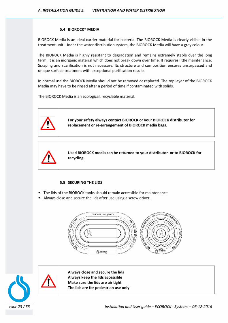
5.5 SECURING THE LIDS
The lids of the BIOROCK tanks should remain accessible for maintenance Always close and secure the lids after use using a screw driver.
Always close and secure the lids Always keep the lids accessible Make sure the lids are air tight The lids are for pedestrian use only
A. INSTALLATION GUIDE > 6. STOPPING AND RE-STARTING THE SYSTEM
PAGE 24 / 55 Installation and User guide – ECOROCK - Systems – 06-12-2016
6. STOPPING AND RESTARTING THE SYSTEM
The establishment of an efficient biomass varies. The system start-up period differs depending on the system size, its location, the temperature and especially the conditions of use. For long periods of shutdown or non-use of the system (absence periods), no special precautions are required. The sewage system will re-start as facilities are used again and will not require any particular attention. For absence periods exceeding six months, it is recommended to empty the Primary Tank and refill with fresh water. If the unit is equipped with an electric ventilator, it is best to shut it down during the absence period and to check and clean it before the restart. If a pump station is installed, it is best to commission it and clean it before the shutdown period. The BIOROCK system remains efficient after a shutdown period.
7. CONFORMITY AND WORK COMPLETION
In all cases, the owner and the installer will jointly complete the installation checklist for BIOROCK Sewage Treatment Plants (Appendix 5) and send it back to the manufacturer at the address listed. The document is attached to the user's guide. This completed document validates the warranty when received by the manufacturer.
8. RECOMMENDATIONS FOR USE AND MAINTENANCE
See the procedures in Part B of this Manual; User Guide.
9. COMPLIANCE WITH REGULATIONS AND STANDARDS
The ECOROCK units comply with all requirements of EN 12566-3 + A2, 12566-6 and the Construction Product Regulations. Performance tests for the CE marking of BIOROCK units were produced and validated by the European Platform notified as CERTIPRO (notification NB 1476) located in MOL, Belgium.

A. INSTALLATION GUIDE > 10. WARRANTY
PAGE 25 / 55 Installation and User guide – ECOROCK - Systems – 06-12-2016
10. WARRANTY
10 years warranty on the BIOROCK® media *1
25 years warranty on the BIOROCK® tanks *
2
*1 The 10 years warranty shall only apply if the annual maintenance is carried out by a BIOROCK approved installer or supervised by a trained BIOROCK Certified professional
*2 The 25 years warranty shall only apply if the installation is carried out by a BIOROCK approved installer or supervised by trained BIOROCK Certified professional
Manufacturer’s Warranty - Terms and Conditions:
Content of BIOROCK warranty: Every BIOROCK treatment plant leaving the production line is inspected and verified according to ISO 9001 standards. The guarantee covers the tanks, materials and parts. As the operation of the system is linked to the use of the products and not the manufacturing, the warranty does not apply to the function of the plants. If a defect in the manufacture of the product is acknowledged by the supplier, the guarantee is limited to the replacement of the defective parts, this excludes any other expenses. Defective equipment and associated accessories should will be made available to the manufacturer and repackaged in the original packaging if necessary. The warranty is subject to installation and operation as per the manufacturer`s instructions and in accordance with good installation practices. The warranty will not apply in the event of: - Failure to comply with the basic design data for the wastewater treatment plant; - failure to return the completed commissioning form / or failure to issue a valid notice of conformity when commissioning is complete; - Failure to follow installation instructions detailed in the Installation Guide, for the primary tank and effluent filter (including the water tightness test) and the treatment unit; - Failure to present or regularly update the maintenance reports by the user (the maintenance report can be found in the manual); - Failure to comply with other requirements, norms, local regulations or common standards; - Damage caused by any accidental or climatic events, beyond our control. Activation of the BIOROCK warranty: In order to activate the BIOROCK Warranty, the owner of the installed products must complete the approval certificate correctly (Appendix 5 "BIOROCK Installation and user guide”). This form must be completed by both the installer and person commissioning the system, it should then be returned to the address indicated on the document. Length of the BIOROCK warranty: Annual maintenance is a condition for the manufacturer’s warranty. This must be carried out by a trained and qualified contractor. The maintenance must be carried out to the manufacturer’s instructions as specified in the user guide.
A. INSTALLATION GUIDE > 10. WARRANTY
PAGE 26 / 55 Installation and User guide – ECOROCK - Systems – 06-12-2016
The owner must complete the maintenance book and keep it up-to-date by adding any maintenance and commissioning activities carried out on the BIOROCK plant. Attention: Sludge emptying documents - confirmation of emptying, receipts, dates and volumes etc issued by the contractor must also be retained. The maintenance book must be made available in the event of a complaint. BIOROCK warranty: - 10 years on the BIOROCK Media (biological part of the treatment plant).
- 25 years on BIOROCK tanks
- 2 years on electrical options, supplied by BIOROCK
Condition of delivery: In the case of incomplete delivery (missing equipment or accessories) or damage observed on delivery, these remarks / observations should be listed on the carrier delivery note or bill. The carrier and the supplier must be informed within 48 hours or 2 business days. Follow the maintenance instructions and visual controls to maintain a reliable and durable system. Please contact your dealer with any question.

B. USER GUIDE
PAGE 27 / 55 Installation and User guide – ECOROCK - Systems – 06-12-2016
B. USER GUIDE
FOR THE
BIOROCK SYSTEMS:
ECOROCK-1500 ECOROCK-2000 ECOROCK-3000

B. USER GUIDE – TABLE OF CONTENTS
PAGE 28 / 55 Installation and User guide – ECOROCK - Systems – 06-12-2016
TABLE OF CONTENTS
1. SAFETY INSTRUCTIONS .................................................................................................... 29 2. SUSTAINABLE DEVELOPMENT .......................................................................................... 30
2.1 Useful information ....................................................................................................................... 30
2.1.1. Sustainability ................................................................................................................ 30 2.1.2. Waste disposal ............................................................................................................. 30
2.2 Polyethylene and PVC .................................................................................................................. 31
2.2.1. Energy recovery ............................................................................................................ 31 2.2.2. Material recycling ......................................................................................................... 31 2.2.3. The BIOROCK Media ..................................................................................................... 31
3. OPERATING AND MAINTENANCE INSTRUCTIONS ............................................................. 32
3.1 Primary Tank and Effluent filter .................................................................................................. 33 3.2 ECOROCK Treatment Unit ............................................................................................................ 35

B. USER GUIDE > 1. SAFETY INSTRUCTIONS
PAGE 29 / 55 Installation and User guide – ECOROCK - Systems – 06-12-2016
1. Safety instructions Related to the installation and operation of an ECOROCK treatment plant
NOTE: Consult with certified professionals regarding all installation and maintenance work, and for all operations undertaken on this sewage treatment plant. Your distributor and/or your installer will advise you on how to set up a maintenance contract.
NOTE: Household wastewater contains human faeces (excrement). This means that wastewater may contain very noxious pathogenic bacteria. Under certain conditions (for instance stagnant wastewater, high temperatures etc.) these noxious pathogenic bacteria may be present in large numbers. Therefore, always use plastic gloves and proper disinfectants if you come into contact with wastewater or with parts which have been in contact with wastewater. The term wastewater also includes the final effluent (the purified wastewater from the BIOROCK® System).
NOTE: The effluent CANNOT be reused for any other purpose other than discharge into the surface water or infiltration into the soil. The water may contain traces of bacteria, which under certain circumstances (stagnant water, high temperature etc.) may grow in large numbers and be potentially harmful to human health.
NOTE: The final effluent (the “clean” water from the System) is NOT drinkable.
NOTE: Always keep the lid closed and open it only for inspections and maintenance work. Never leave the lids and inspection points unsupervised while open. Lids are for pedestrian use only.
NOTE: Do not put your head directly into any septic tank or sewage treatment plant through the manhole even to "have a look" or in an effort to find the cause of a malfunction. Noxious gases may accumulate in the system and may interfere with respiration and cause nausea, dizziness and in very extreme cases loss of consciousness.
NOTE: Do not install, repair, change or check electrical components yourself; this can be extremely dangerous due to the combination of electricity and water especially when using 230 Volt. Leave this task to a qualified electrician, who can install the system in accordance with NEN 1010. When using 12 Volt electrical accessories, there is no danger of electrocution, but contact a qualified electrician if in doubt.
NOTE: Never smoke near the work area while the operations described in this manual are being carried out, and never enter the work area without having taken all the prior precautions for ventilation and atmospheric testing as prescribed in the applicable local regulatory provisions.
NOTE: Any risks during the installation are related to excavation or handling of material. While installing the tanks, use a sling hung from the 4 corners of the upper part of the tank. Make sure that no one is in the maneuvering area, and do not position yourself under the load.

B. USER GUIDE 2. SUSTAINABILITY
PAGE 30 / 55 Installation and User guide – ECOROCK - Systems – 06-12-2016
2. SUSTAINABLE DEVELOPMENT In order to support sustainable development, BIOROCK has developed a sewage treatment plant with a very low carbon footprint. It does not need electricity, mechanical parts or chemicals to work. Selecting a product that offers a sustainable solution to the problem of waste disposal is a key factor in protecting the environment. The construction market is becoming increasingly aware of the need for environmentally sustainable solutions to issues such as sewage treatment and the disposal of effluent from off-mains systems. There is a clear shift towards responsible and sustainable products. BIOROCK® sewage treatment systems are the acknowledged leader in this rapidly changing market. All materials used in the manufacture and assembly of the BIOROCK systems equipment are corrosion-resistant to ensure a long term installation. The main components are polyethylene (Tanks), PVC (piping) and the BIOROCK media. Nearly 100% of the components can be recycled.
2.1 USEFUL INFORMATION
2.1.1 Sustainability Sustainable development is based on three factors: Protection of the environment, social progress, and economic development. Both production methods and consumption must respect both human beings and the natural environment to enable all inhabitants on Earth to meet their basic needs (food, clothing, education, work, living in a healthy environment). Education for sustainable development is fundamental: it is the main necessary step towards a general change in mindset and behavior. This change in mindset for each of us (citizens, businesses, local authorities, governments, international institutions) is necessary to address threats to the Earth (social inequality, industrial and health risks, climate change, biodiversity loss, etc.).
2.1.2 Waste disposal
Waste results from the operation of treatment systems and maintenance of drainage systems for sewage and rainwater. These are predominantly organic waste (sludge, grease, wastewater treatment plant waste, drain material, etc.) or mineral (sand treatment plant, sludge, sewage sands, etc.). Sludge produced in the Primary Tank must be removed by a licensed contractor. The used BIOROCK media can be returned to BIOROCK or to a BIOROCK Certified Partner for recycling. The effluent filter for the Primary Tank can be disposed after rinsing.

B. USER GUIDE 2. SUSTAINABILITY
PAGE 31 / 55 Installation and User guide – ECOROCK - Systems – 06-12-2016
2.2 POLYETHYLENE AND PVC
PE and PVC are recoverable using different processes
2.2.1 Energy recovery
Incineration leads to energy recovery. However it may generate pollutants and gas.
2.2.2 Material recycling Recycling plastics of this nature (PVC, PE) into granules or powder which can be sold as an alternative to virgin material in manufacturing.
2.2.3 The BIOROCK® media The BIOROCK® media is inert but if there is a need to replace some of the media the dirty bags (once removed) must be cleaned before recycling. The used BIOROCK® Media can be returned to BIOROCK for recycling.
Always use a professional waste disposal contractor to periodically remove sludge. Once removed, the sludge will be disposed safely at an approved facility.

B. USER GUIDE 3. RECOMMENDATIONS FOR OPERATION AND MAINTENANCE
PAGE 32 / 55 Installation and User guide – ECOROCK - Systems – 06-12-2016
3. OPERATING & MAINTENANCE RECOMMENDATIONS An annual service and maintenance contract should be set up for your BIOROCK system. Contact your dealer if necessary or contact us for more details about the closest dealer to you. BIOROCK highly recommends users to set up a maintenance contract with their local dealer or Certified Installer to ensure the long lasting efficiency of BIOROCK products. Completing the maintenance book together with a BIOROCK Certified Professional is a condition for warranty. However, should you be unable to get this service locally, BIOROCK can provide a maintenance planning schedule giving an overview of the maintenance procedures. This planning schedule will allow a professional in the wastewater industry to provide the maintenance service. Please check with local authorities how often the primary compartment should be emptied as this should be in line with local regulations. The summary below indicates the commissioning of your sewage treatment plant. Your sewage treatment plant can be free from any failures as the BIOROCK system does not require electricity. (In normal operation, and following the maintenance recommendations)
GENERALLY: Every year:
Visually check the water tightness of the complete system Check the ventilation Check if there are any smells exiting the tanks
PRIMARY TANK Every year:
Check the sludge level Empty the Primary Tank if the sludge level is > 50% Change the effluent filter if necessary or change after emptying the Primary Tank Take a sample of the effluent form the Primary Tank and check quality visually
ECOROCK UNIT Every year:
Clean the water distribution pipe Check and re-adjust the water distribution pipe if necessary Check the first layer of BIOROCK Media Rinse or replace the first layer of BIOROCK® Media if necessary Remove and clean the alarm Take a sample of the outgoing water (final effluent) and check for clearness and odour.
Clearness means that the water contains few suspended particles. The colour may vary from neutral to dark yellow. The odour of the water will normally be neutral to light ammonia.
Neutral Dark yellow
B. USER GUIDE 3. RECOMMENDATIONS FOR OPERATION AND MAINTENANCE
PAGE 33 / 55 Installation and User guide – ECOROCK - Systems – 06-12-2016
3.1 PRIMARY TANK AND EFFLUENT FILTER For a non-BIOROCK Primary Tank please refer to the maintenance schedule from the manufacturer of the Primary Tank that you have purchased. However, should you be unable to get information, BIOROCK can provide a maintenance planning schedule giving you an overview of the maintenance procedures. Please check how often you need to empty your Primary Tank in line with local regulations. Please check if the Primary Tank has the required efficiency that is required by BIOROCK. See page 9, Chapter 2.1.
MAINTENANCE GUIDE FOR THE PRIMARY TANK (PT) AND THE EFFLUENT FILTER (EF)
Sampling of the pre-treated waste water coming from the Primary Tank Take your first sample 6 months after commissioning, then once a year, or at the same time as the Primary Tank is emptied
Visually check the pre-treated wastewater quality Take a sample (with rubber or latex domestic use gloves) of the purified sewage water in a clean glass. The color of the water should range from light brown to yellow, from turbid to very turbid, but very
little deposit should show at the bottom of the sample after it has rested for twenty minutes The purified water may have a slight (septic) odor
If the water looks different or you find increased deposits in the pre-treated waste water, this may be caused by:
Water flowing too fast through the PT, too short retention time (hydraulic overload). Check that no rainwater run-off system passes through the installation.
The volume of the Primary Tank is too small to accommodate normal usage Incorrect disposal of harmful, toxic, anti-bacterial or non-biodegradable products into the installation You may need to call a certified septic tank cleaning company to empty the PT and to clean it
(skimming off the fats and floating matter — the surface layer). Never completely empty the PT; always leave a layer of sludge at the bottom to ensure that it continues to function correctly after it has been emptied
In all of these cases, you should consult the documents and user manuals provided by the tank manufacturer
If you notice any foul odors, these may be caused by:
The ventilation system is not working properly The ventilation system is not airtight at the T-piece of the water inlet in the PT The internal waste water system in the house is not vented properly with a soil vent pipe The inspection seals or the seals on the Primary Tank are not air- or watertight Insufficient airflow through the ventilation system; ventilation pipes too small - diameter >100 mm, a
badly positioned wind driven ventilator, etc. A block in the airflow in the tank itself, because the surface layer has become too thick (for example
fats & floating matter) or a baffle wall that is too high.
In all of these cases, you should consult the documents and user manuals provided by the manufacturer.
B. USER GUIDE 3. RECOMMENDATIONS FOR OPERATION AND MAINTENANCE
PAGE 34 / 55 Installation and User guide – ECOROCK - Systems – 06-12-2016
Effluent Filter cleaning and replacement The BIOROCK effluent filter should be checked annually and cleaned (rinsed) or replaced when required.
Open the cover at the PVC pipe that provides access to the Effluent Filter
Take the rod holding the Effluent Filter and lift it carefully to remove
Beware of flying particles
The Effluent Filter should be replaced when necessary, when its condition is no longer fit for efficient filtering of suspended solids.
Emptying of the Primary Tank The first emptying of the Primary Tank takes place, when the sludge level reaches 50% of the Primary Tank volume, unless superseded by local regulations.
Always use a certified septic tank emptier. Replace the Effluent Filter at least every two years. The frequency with which the tank is emptied may be adapted according to the nature of the
operation and how many people live in the building. It must be emptied when the sludge level reaches 50%.
The cleaning certificate, written by the certified septic tank cleaning company, must be retained by the owner in and placed in the maintenance guide.
The septic tank emptier should pressure wash the sides of the tank and the Effluent Filter to remove the accumulated fats and other matter.
The tanker, while emptying the Primary Tank, must not be parked any nearer than 4 meters (14’) from the installation to ensure and maintain stability.
Refill the Primary Tank with clean water after emptying before resuming normal operation. Further information: The quantity of sludge produced is influenced by how the unit is used (size, frequent overloads, type of waste water, routine maintenance). Each unit is different.
We estimate that an installation of 5 PE will produce a maximum of +/- 900 liters of sludge in the first year. The quantity of sludge produced will reduce over the first few years: normally after the fourth or fifth year, the residual quantities will have decreased by 40%. When emptying, the cleaner must leave a few centimeters of sludge at the bottom of the tank; the bacteria that break down the sludge are specific and take a long time to develop.
Sludge production in Primary Tank
Capacity in Person Equivalent ECOROCK-1500
6 PE ECOROCK-2000
10 PE ECOROCK-3000
15 PE
Sludge production 1.100 Liters/year 1.825 Liters/year 2.700 Liters/year

B. USER GUIDE 3. RECOMMENDATIONS FOR OPERATION AND MAINTENANCE
PAGE 35 / 55 Installation and User guide – ECOROCK - Systems – 06-12-2016
3.2 THE ECOROCK TREATMENT UNIT
The 10 years warranty shall only apply if the annual maintenance is carried out by a BIOROCK approved installer or supervised by a trained BIOROCK Certified professional
MAINTENANCE PLANNING FOR THE ECOROCK SEWAGE TREATMENT PLANT
Only take a sample from running water. Never use a sample from stagnant water
Effluent sampling: 6 months after start-up, then every year
Only take a sample from running water. Never use a sample from stagnant water Take a sample of the outgoing water (final effluent) and check for clearness and odour.
Clearness means that the water contains few suspended particles. The colour may vary from neutral to dark yellow. The odour of the water will normally be neutral to light ammonia
Sampling can be done via any sampling point or directly at the outlet of the tank Always wear rubber or latex domestic gloves when taking a sample The outgoing water should be clear. A little deposit might show at the bottom of the sampling
glass after it has rested for twenty minutes The water shouldn't have a septic or nauseating odor. It may have the characteristic smell of
fresh humus If the visual check seems to show a malfunction (turbid treated water, presence of deposits or
suspended matter, nauseating or septic odor), take the sample to a certified laboratory for testing
If the laboratory confirms a problem with the water quality check: - if the primary tank is functioning properly - the quality of the pre-treated water from the Primary Tank - if there are any fats or solids on the surface of the BIOROCK Media - the water distribution in the BIOROCK unit - if the ventilation of the Primary Tank is functioning properly - if the ventilation of the BIOROCK system is functioning properly - if the unit is correctly sized for its required capacity - the presence of harmful, toxic, antibacterial or non-biodegradable products in the
installation
If you notice the presence of increased deposits (suspended matter) in the treated waste water or if the unit is clogged up:
A prolonged overload of pollution in the installation, repeated misuse of the primary tank (late sludge removal, an inefficient effluent filter and neglect over several years) can lead to the saturation of the BIOROCK Media in the bioreactor.

B. USER GUIDE 3. RECOMMENDATIONS FOR OPERATION AND MAINTENANCE
PAGE 36 / 55 Installation and User guide – ECOROCK - Systems – 06-12-2016
Cleaning or replacement procedure for the BIOROCK® Media:
The BIOROCK Media can be removed using a metal hook or a rake. The BIOROCK media can be returned to a local BIOROCK partner. BIOROCK will arrange media recycling after use. .
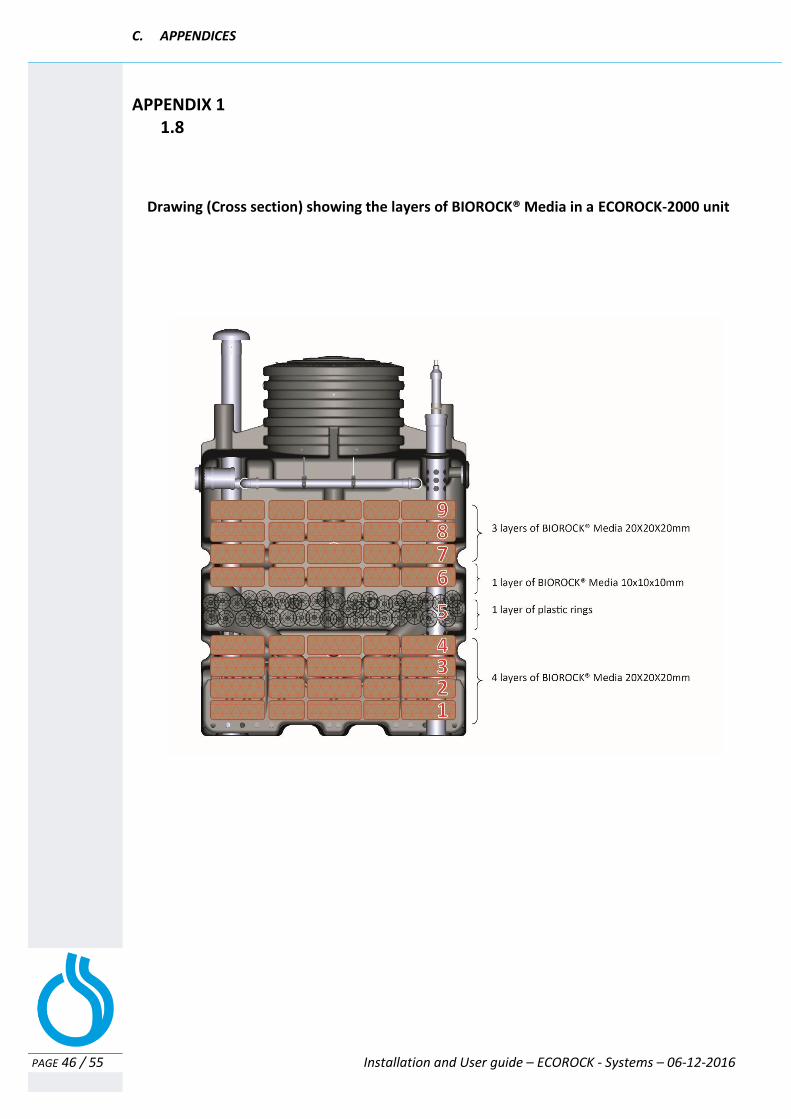
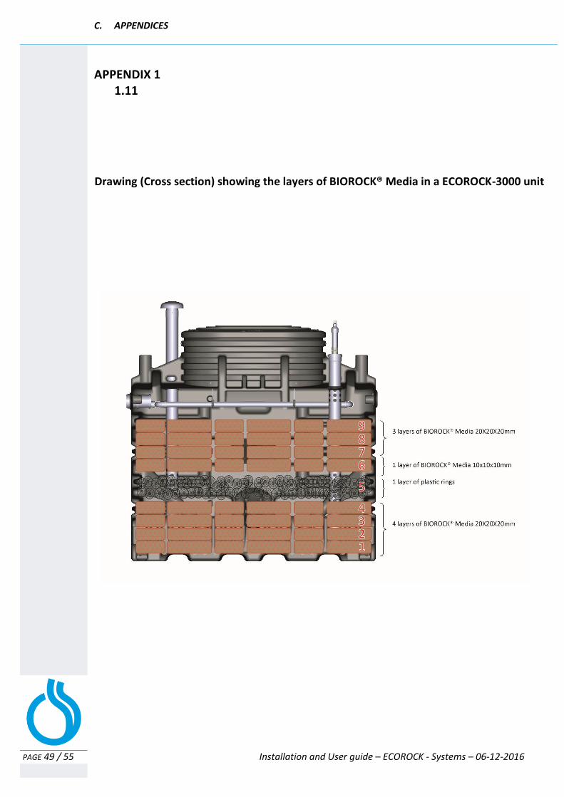
Build-up of the BIOROCK media from bottom to top:
Layers 1 to 4 Layer 5 Layer 6 Layers 7 to 9
BIOROCK® media 20x20x20 mm
plastic aeration rings BIOROCK® media
10x10x10 mm BIOROCK® media
20x20x20 mm
While replacing the bags of BIOROCK Media, make sure that each layer of bags completely covers the surface of the unit, ensure that there is no free space between the bags. The bags of BIOROCK Media should always overlap each other. Ensure that the aeration rings are put back to the same position and height. BIOROCK can quote media replacement and recycling through its network of distributors and installers. Contact us for your closest BIOROCK Certified Professional.
A well performing ECOROCK unit does not produce a bad smell, it should have a smell of fresh humus. Problems with bad smells are generally caused by a poor ventilation.
Check the alarm To be done annually Clean the float and the pipe with clean water. Visually check the alarm positioning: Lift lightly and let it go down.
If the BIOROCK Media is clogged, remove the bags of BIOROCK media until you get to clean bags If possible clean the BIOROCK media with a normal water
hose. Wash the bags in a basin of water, agitating them aggressively, so that all of the sludge that has accumulated in the bags is removed If it is impossible to clean the BIOROCK media, replace with
new bags Before returning the BIOROCK media bags, clean the inside
of the tank and if necessary the Aeration rings Carefully place the bags back in the unit as detailed below

B. USER GUIDE 3. RECOMMENDATIONS FOR OPERATION AND MAINTENANCE
PAGE 37 / 55 Installation and User guide – ECOROCK - Systems – 06-12-2016
Check water tightness of the water inlet pipe and the water distribution pipe To be done annually
Visually check the water tightness of the water inlet pipe from the Primary Tank.
Check that the water distribution pipe provides an equal distribution of water to the BIOROCK media To be done annually Clean the inside of the water distribution pipe with clean water. Preferably above an open PT.
1. Unclip the water distribution pipe and remove the pipe system from the tank 2. Adjust the height/level of the water distribution pipes using the threaded supports 3. The discharge angle can also be adjusted by twisting the pipes
Check the BIOROCK media and its possible settlement To be done annually
The BIOROCK Media may settle progressively as the water flows through it. This generally occurs after some years of usage. Should this occur, just shake the BIOROCK media bags manually and placed them back in the tank. Make sure that each layer of bags completely covers the surface of the Treatment Unit with no free space between the bags which should always overlap each other. If the inspection shows an accumulation of suspended solids at the top layer of BIOROCK media, then the BIOROCK media of the top layer may need to be cleaned more thoroughly. (see Ch. “Cleaning or replacement procedure for the BIOROCK Media”)
Any long-lasting water accumulation on the surface of the bags indicates that it is necessary to clean at least the first layer of BIOROCK media.
The frequency of cleaning and / or replacement of the BIOROCK media bags depend on the quantity and quality of effluent leaving the Primary Tank. Checking the Effluent Filter and Primary Tank on an annual basis is very important.
If you still notice the presence of fats: If flow difficulties persist after the above cleaning operations, check for an accumulation of fat in the Primary Tank and at the Effluent Filter.
2 1 3
C. APPENDICES
PAGE 38 / 55 Installation and User guide – ECOROCK - Systems – 06-12-2016
C. APPENDICES
Appendix 1: Technical drawings of the various components
1.1 Drawing of an ECOROCK-1500 treatment unit (6PE) ........................................................... 39
1.2 Aeration & Water distribution schematic of an ECOROCK-1500 (6PE) ............................... 40
1.3 Cross section of the layers of BIOROCK® Media in an ECOROCK-1500 unit ........................ 41
1.4 Drawing of an ECOROCK-1500 treatment unit (8PE) ........................................................... 42
1.5 Aeration & Water distribution schematic of an ECOROCK-1500 (8PE) ............................... 43
1.6 Drawing of an ECOROCK-2000 treatment unit .................................................................... 44
1.7 Aeration & Water distribution schematic of an ECOROCK-2000 ......................................... 45
1.8 Cross section of the layers of BIOROCK® Media in an ECOROCK-2000 unit ........................ 46
1.9 Drawing of an ECOROCK-3000 treatment Unit .................................................................... 47
1.10 Aeration & Water distribution schematic of an ECOROCK-3000 ......................................... 48
1.11 Cross section of the layers of BIOROCK® Media in an ECOROCK-3000 unit ........................ 49
Appendix 2: Installation drawings of the ECOROCK installations
2.1 Drawing (Cross section) of 1x ECOROCK-1500 plant in dry ground conditions (6PE) .......... 50
2.2 Drawing (Cross section) of 1x ECOROCK-1500 in high ground water conditions (6PE) ........ 50
2.3 Drawing (Cross section) of 1x ECOROCK-1500 plant in dry ground conditions (8PE) ............ 51
2.4 Drawing (Cross section) of 1x ECOROCK-1500 in high ground water conditions (8PE) ......... 51
2.5 Drawing (Cross section) of 1x ECOROCK-2000 plant in dry ground conditions ................... 52
2.6 Drawing (Cross section) of 1x ECOROCK-2000 in high ground water conditions ................ 52
2.7 Drawing (Cross section) of 1x ECOROCK-3000 plant in dry ground conditions ................... 53
2.8 Drawing (Cross section) of 1x ECOROCK-3000 in high ground water conditions ................ 53
Appendix 4:
REGISTRATION FORM FOR YOUR BIOROCK® PLANT ................................................................. 54
Appendix 5:
WARRANTY ............................................................................................................................................ 55
C. APPENDICES
PAGE 39 / 55 Installation and User guide – ECOROCK - Systems – 06-12-2016
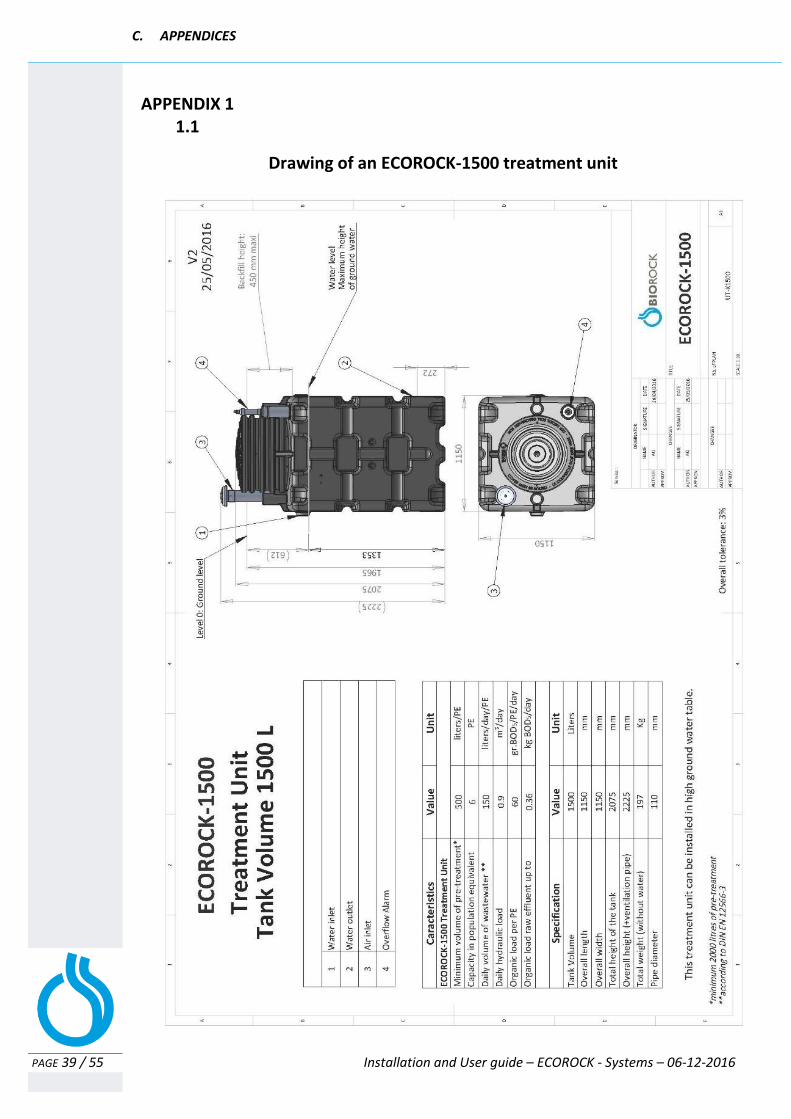
Drawing of an ECOROCK-1500 treatment unit
APPENDIX 1 1.1
C. APPENDICES
PAGE 40 / 55 Installation and User guide – ECOROCK - Systems – 06-12-2016
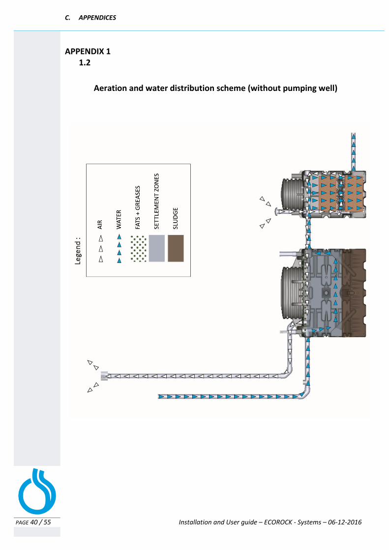
APPENDIX 1 1.2
Aeration and water distribution scheme (without pumping well)
C. APPENDICES
PAGE 41 / 55 Installation and User guide – ECOROCK - Systems – 06-12-2016
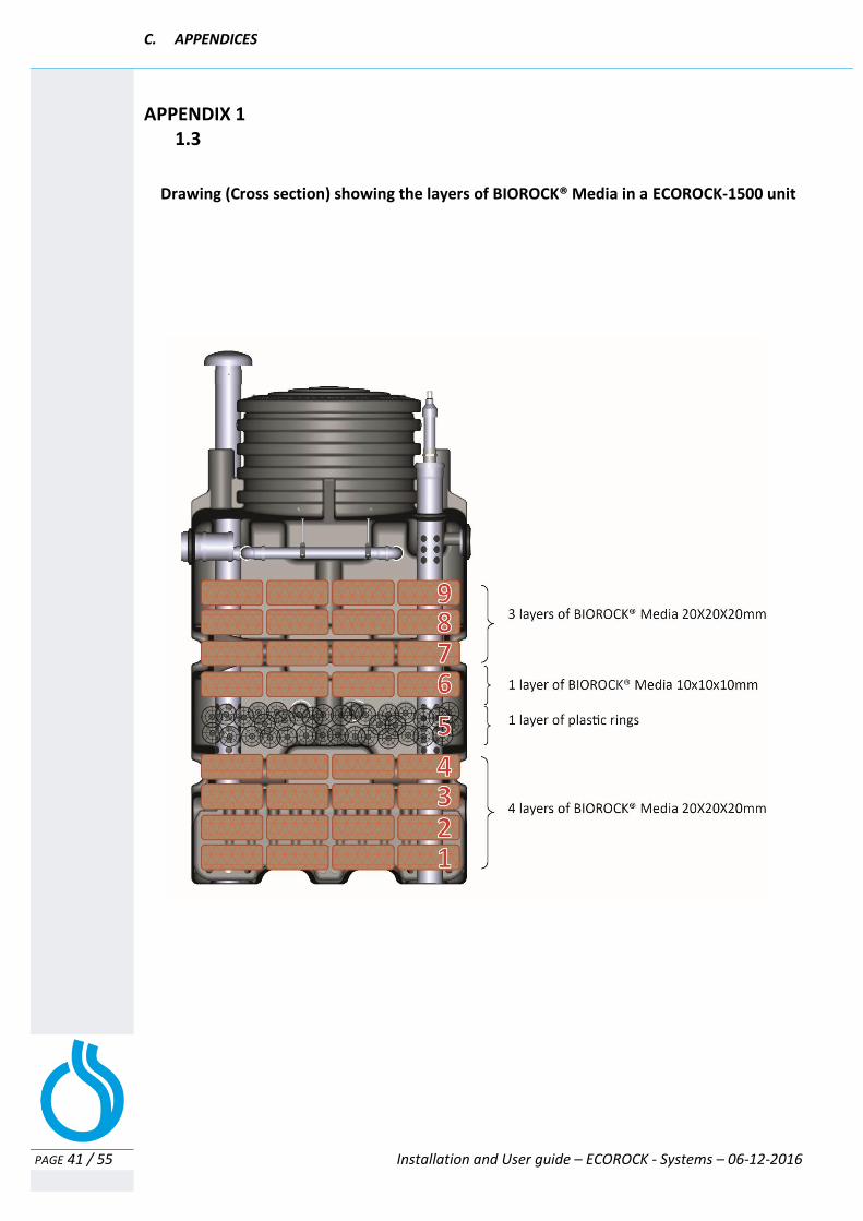
APPENDIX 1 1.3
Drawing (Cross section) showing the layers of BIOROCK® Media in a ECOROCK-1500 unit
C. APPENDICES
PAGE 42 / 55 Installation and User guide – ECOROCK - Systems – 06-12-2016
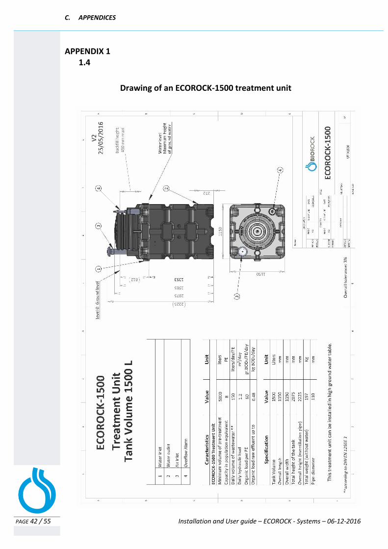
APPENDIX 1 1.4
Drawing of an ECOROCK-1500 treatment unit
C. APPENDICES
PAGE 43 / 55 Installation and User guide – ECOROCK - Systems – 06-12-2016
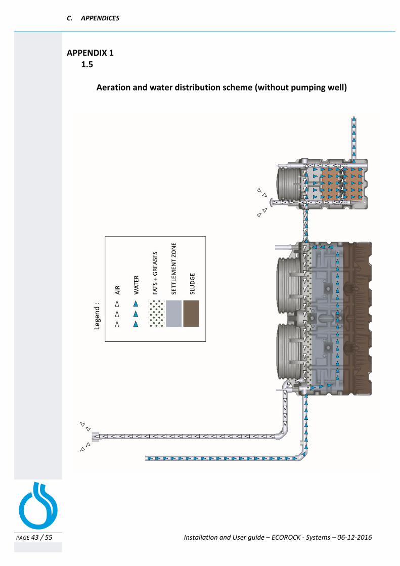
APPENDIX 1 1.5
Aeration and water distribution scheme (without pumping well)

C. APPENDICES
PAGE 44 / 55 Installation and User guide – ECOROCK - Systems – 06-12-2016
APPENDIX 1 1.6
Drawing of an ECOROCK-2000 treatment unit
C. APPENDICES
PAGE 45 / 55 Installation and User guide – ECOROCK - Systems – 06-12-2016
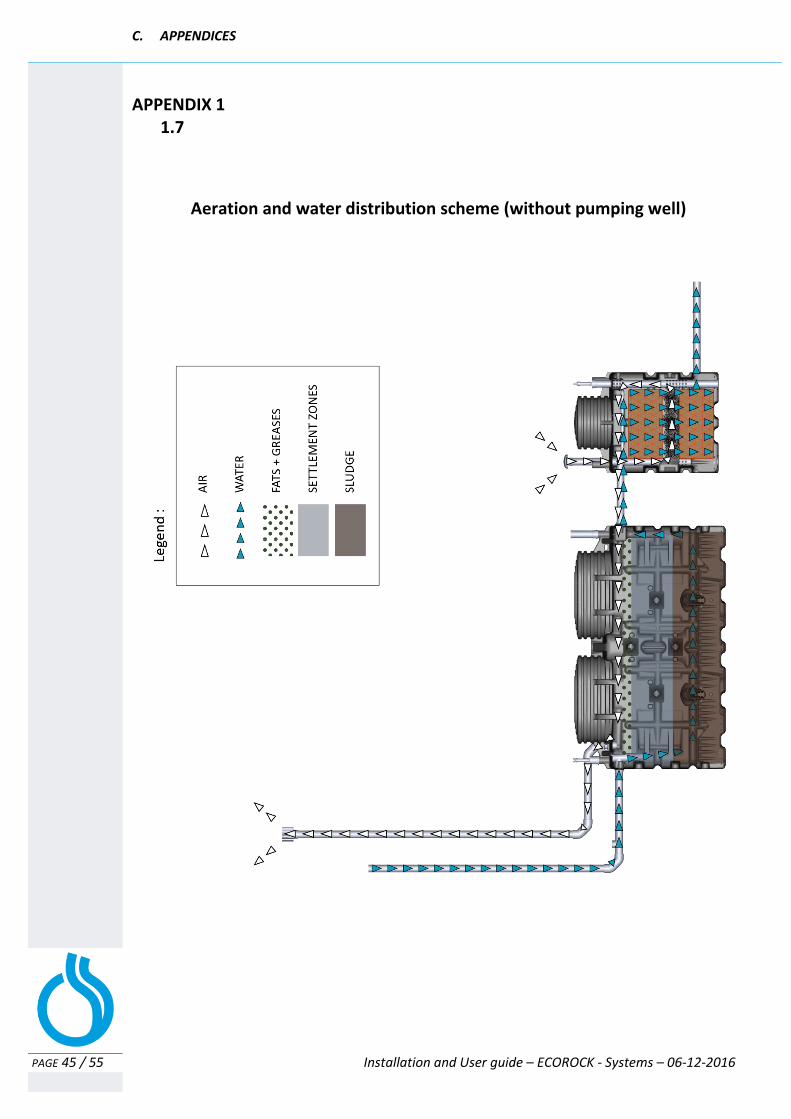
APPENDIX 1 1.7
Aeration and water distribution scheme (without pumping well)
C. APPENDICES
PAGE 46 / 55 Installation and User guide – ECOROCK - Systems – 06-12-2016
APPENDIX 1 1.8
Drawing (Cross section) showing the layers of BIOROCK® Media in a ECOROCK-2000 unit
C. APPENDICES
PAGE 47 / 55 Installation and User guide – ECOROCK - Systems – 06-12-2016
APPENDIX 1 1.9
Drawing of an ECOROCK-3000 treatment unit
C. APPENDICES
PAGE 48 / 55 Installation and User guide – ECOROCK - Systems – 06-12-2016
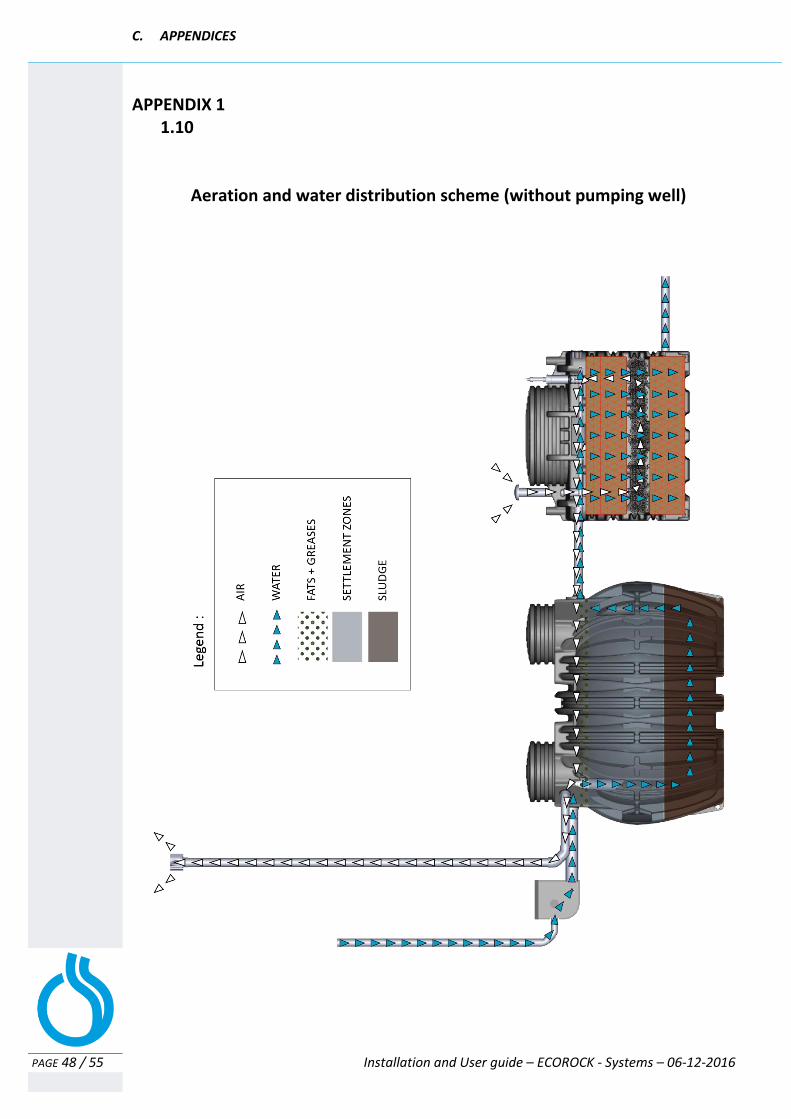
APPENDIX 1 1.10
Aeration and water distribution scheme (without pumping well)
C. APPENDICES
PAGE 49 / 55 Installation and User guide – ECOROCK - Systems – 06-12-2016
APPENDIX 1 1.11
Drawing (Cross section) showing the layers of BIOROCK® Media in a ECOROCK-3000 unit

C. APPENDICES
PAGE 50 / 55 Installation and User guide – ECOROCK - Systems – 06-12-2016
APPENDIX 1 2.1
APPENDIX 2 2.2

C. APPENDICES
PAGE 51 / 55 Installation and User guide – ECOROCK - Systems – 06-12-2016
APPENDIX 2 2.3
APPENDIX 2
2.4

C. APPENDICES
PAGE 52 / 55 Installation and User guide – ECOROCK - Systems – 06-12-2016
APPENDIX 2 2.5
APPENDIX 2 2.6

C. APPENDICES
PAGE 53 / 55 Installation and User guide – ECOROCK - Systems – 06-12-2016
APPENDIX 2 2.7
APPENDIX 2
2.8
C. APPENDICES
PAGE 54 / 55 Installation and User guide – ECOROCK - Systems – 06-12-2016
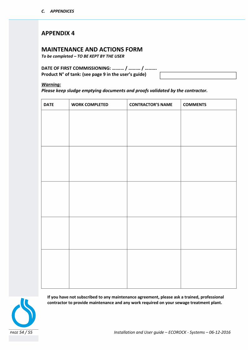
APPENDIX 4
MAINTENANCE AND ACTIONS FORM To be completed – TO BE KEPT BY THE USER
DATE OF FIRST COMMISSIONING: ….…… / …….… / ………. Product N° of tank: (see page 9 in the user’s guide)
Warning: Please keep sludge emptying documents and proofs validated by the contractor.
DATE WORK COMPLETED CONTRACTOR’S NAME COMMENTS
If you have not subscribed to any maintenance agreement, please ask a trained, professional contractor to provide maintenance and any work required on your sewage treatment plant.

C. APPENDICES
PAGE 55 / 55 Installation and User guide – ECOROCK - Systems – 06-12-2016