installation and configuration note for the catalyst 4500 series ac ... · perigos envolvidos no...
TRANSCRIPT
Installation and Configuration Note for the Catalyst 4500 Series AC Power Shelf
Product Numbers:
WS-P4502-1PSU—Catalyst 4500 AC power shelf with 2500 W power supply
PWR-4502—Redundant 2500 W power supply for AC power shelf
CAB-4502-DC-2M—2-m DC cable set
CAB-4502-DC-60-CM—60-cm DC cable set
WS-X4500-PS01—Service Access Cover
This publication describes how to install the Catalyst 4500 series AC power shelf. The AC power shelf provides additional power for switching modules that need to provide power to in-line devices such as IP telephones.
ContentsThis document contains these sections:
• Safety Overview, page 2
• Installing the AC Power Shelf, page 7
• Related Documentation, page 17
• Obtaining Documentation and Submitting a Service Request, page 17
Corporate Headquarters:
© 2005 Cisco Systems, Inc. All rights reserved.
Cisco Systems, Inc., 170 West Tasman Drive, San Jose, CA 95134-1706 USA

Safety Overview
Safety OverviewThroughout this publication, safety warnings appear in procedures that may harm you if performed incorrectly. A warning symbol precedes each warning statement.
Warning IMPORTANT SAFETY INSTRUCTIONS
This warning symbol means danger. You are in a situation that could cause bodily injury. Before you work on any equipment, be aware of the hazards involved with electrical circuitry and be familiar with standard practices for preventing accidents. Use the statement number provided at the end of each warning to locate its translation in the translated safety warnings that accompanied this device. Statement 1071
SAVE THESE INSTRUCTIONS
Waarschuwing BELANGRIJKE VEILIGHEIDSINSTRUCTIES
Dit waarschuwingssymbool betekent gevaar. U verkeert in een situatie die lichamelijk letsel kan veroorzaken. Voordat u aan enige apparatuur gaat werken, dient u zich bewust te zijn van de bij elektrische schakelingen betrokken risico's en dient u op de hoogte te zijn van de standaard praktijken om ongelukken te voorkomen. Gebruik het nummer van de verklaring onderaan de waarschuwing als u een vertaling van de waarschuwing die bij het apparaat wordt geleverd, wilt raadplegen.
BEWAAR DEZE INSTRUCTIES
Varoitus TÄRKEITÄ TURVALLISUUSOHJEITA
Tämä varoitusmerkki merkitsee vaaraa. Tilanne voi aiheuttaa ruumiillisia vammoja. Ennen kuin käsittelet laitteistoa, huomioi sähköpiirien käsittelemiseen liittyvät riskit ja tutustu onnettomuuksien yleisiin ehkäisytapoihin. Turvallisuusvaroitusten käännökset löytyvät laitteen mukana toimitettujen käännettyjen turvallisuusvaroitusten joukosta varoitusten lopussa näkyvien lausuntonumeroiden avulla.
SÄILYTÄ NÄMÄ OHJEET
Attention IMPORTANTES INFORMATIONS DE SÉCURITÉ
Ce symbole d'avertissement indique un danger. Vous vous trouvez dans une situation pouvant entraîner des blessures ou des dommages corporels. Avant de travailler sur un équipement, soyez conscient des dangers liés aux circuits électriques et familiarisez-vous avec les procédures couramment utilisées pour éviter les accidents. Pour prendre connaissance des traductions des avertissements figurant dans les consignes de sécurité traduites qui accompagnent cet appareil, référez-vous au numéro de l'instruction situé à la fin de chaque avertissement.
CONSERVEZ CES INFORMATIONS
2Installation and Configuration Note for the Catalyst 4500 Series AC Power Shelf
78-15068-04
Safety Overview
Warnung WICHTIGE SICHERHEITSHINWEISE
Dieses Warnsymbol bedeutet Gefahr. Sie befinden sich in einer Situation, die zu Verletzungen führen kann. Machen Sie sich vor der Arbeit mit Geräten mit den Gefahren elektrischer Schaltungen und den üblichen Verfahren zur Vorbeugung vor Unfällen vertraut. Suchen Sie mit der am Ende jeder Warnung angegebenen Anweisungsnummer nach der jeweiligen Übersetzung in den übersetzten Sicherheitshinweisen, die zusammen mit diesem Gerät ausgeliefert wurden.
BEWAHREN SIE DIESE HINWEISE GUT AUF.
Avvertenza IMPORTANTI ISTRUZIONI SULLA SICUREZZA
Questo simbolo di avvertenza indica un pericolo. La situazione potrebbe causare infortuni alle persone. Prima di intervenire su qualsiasi apparecchiatura, occorre essere al corrente dei pericoli relativi ai circuiti elettrici e conoscere le procedure standard per la prevenzione di incidenti. Utilizzare il numero di istruzione presente alla fine di ciascuna avvertenza per individuare le traduzioni delle avvertenze riportate in questo documento.
CONSERVARE QUESTE ISTRUZIONI
Advarsel VIKTIGE SIKKERHETSINSTRUKSJONER
Dette advarselssymbolet betyr fare. Du er i en situasjon som kan føre til skade på person. Før du begynner å arbeide med noe av utstyret, må du være oppmerksom på farene forbundet med elektriske kretser, og kjenne til standardprosedyrer for å forhindre ulykker. Bruk nummeret i slutten av hver advarsel for å finne oversettelsen i de oversatte sikkerhetsadvarslene som fulgte med denne enheten.
TA VARE PÅ DISSE INSTRUKSJONENE
Aviso INSTRUÇÕES IMPORTANTES DE SEGURANÇA
Este símbolo de aviso significa perigo. Você está em uma situação que poderá ser causadora de lesões corporais. Antes de iniciar a utilização de qualquer equipamento, tenha conhecimento dos perigos envolvidos no manuseio de circuitos elétricos e familiarize-se com as práticas habituais de prevenção de acidentes. Utilize o número da instrução fornecido ao final de cada aviso para localizar sua tradução nos avisos de segurança traduzidos que acompanham este dispositivo.
GUARDE ESTAS INSTRUÇÕES
¡Advertencia! INSTRUCCIONES IMPORTANTES DE SEGURIDAD
Este símbolo de aviso indica peligro. Existe riesgo para su integridad física. Antes de manipular cualquier equipo, considere los riesgos de la corriente eléctrica y familiarícese con los procedimientos estándar de prevención de accidentes. Al final de cada advertencia encontrará el número que le ayudará a encontrar el texto traducido en el apartado de traducciones que acompaña a este dispositivo.
GUARDE ESTAS INSTRUCCIONES
3Installation and Configuration Note for the Catalyst 4500 Series AC Power Shelf
78-15068-04

Safety Overview
Varning! VIKTIGA SÄKERHETSANVISNINGAR
Denna varningssignal signalerar fara. Du befinner dig i en situation som kan leda till personskada. Innan du utför arbete på någon utrustning måste du vara medveten om farorna med elkretsar och känna till vanliga förfaranden för att förebygga olyckor. Använd det nummer som finns i slutet av varje varning för att hitta dess översättning i de översatta säkerhetsvarningar som medföljer denna anordning.
SPARA DESSA ANVISNINGAR
4Installation and Configuration Note for the Catalyst 4500 Series AC Power Shelf
78-15068-04

Safety Overview
Aviso INSTRUÇÕES IMPORTANTES DE SEGURANÇA
Este símbolo de aviso significa perigo. Você se encontra em uma situação em que há risco de lesões corporais. Antes de trabalhar com qualquer equipamento, esteja ciente dos riscos que envolvem os circuitos elétricos e familiarize-se com as práticas padrão de prevenção de acidentes. Use o número da declaração fornecido ao final de cada aviso para localizar sua tradução nos avisos de segurança traduzidos que acompanham o dispositivo.
GUARDE ESTAS INSTRUÇÕES
Advarsel VIGTIGE SIKKERHEDSANVISNINGER
Dette advarselssymbol betyder fare. Du befinder dig i en situation med risiko for legemesbeskadigelse. Før du begynder arbejde på udstyr, skal du være opmærksom på de involverede risici, der er ved elektriske kredsløb, og du skal sætte dig ind i standardprocedurer til undgåelse af ulykker. Brug erklæringsnummeret efter hver advarsel for at finde oversættelsen i de oversatte advarsler, der fulgte med denne enhed.
GEM DISSE ANVISNINGER
5Installation and Configuration Note for the Catalyst 4500 Series AC Power Shelf
78-15068-04

Safety Overview
6Installation and Configuration Note for the Catalyst 4500 Series AC Power Shelf
78-15068-04
Installing the AC Power Shelf
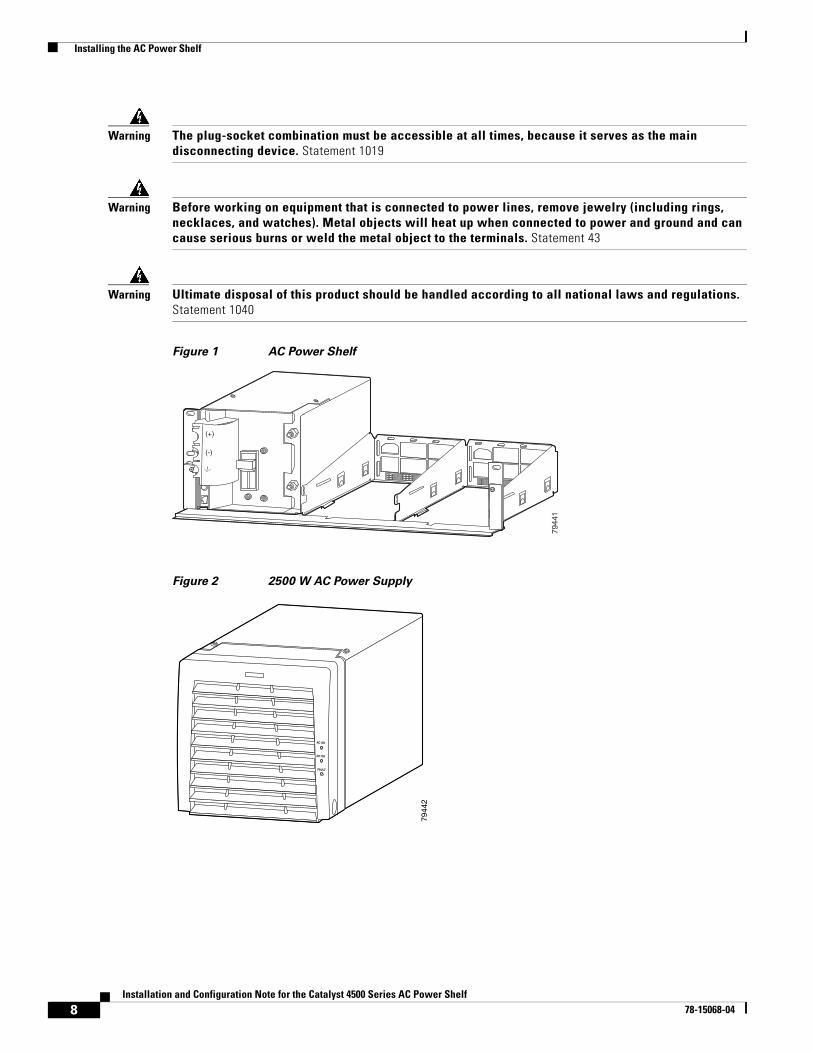
Installing the AC Power ShelfThis section describes how to install the AC power shelf (see Figure 1) in a rack and connect it to your power supplies. You can install one or two 2500 W power supplies (see Figure 2) in the AC power shelf, depending on how much power is required.
Warning Read the installation instructions before connecting the system to the power source. Statement 1004
Warning Only trained and qualified personnel should be allowed to install, replace, or service this equipment. Statement 1030
Warning This unit is intended for installation in restricted access areas. A restricted access area can be accessed only through the use of a special tool, lock and key, or other means of security. Statement 1017
Warning This equipment must be grounded. Never defeat the ground conductor or operate the equipment in the absence of a suitably installed ground conductor. Contact the appropriate electrical inspection authority or an electrician if you are uncertain that suitable grounding is available. Statement 1024
7Installation and Configuration Note for the Catalyst 4500 Series AC Power Shelf
78-15068-04
Installing the AC Power Shelf
Warning The plug-socket combination must be accessible at all times, because it serves as the main disconnecting device. Statement 1019
Warning Before working on equipment that is connected to power lines, remove jewelry (including rings, necklaces, and watches). Metal objects will heat up when connected to power and ground and can cause serious burns or weld the metal object to the terminals. Statement 43
Warning Ultimate disposal of this product should be handled according to all national laws and regulations. Statement 1040
Figure 1 AC Power Shelf
Figure 2 2500 W AC Power Supply
7944
1
(+)
(-)
AC OK
DC OK
FAULT
7944
2
8Installation and Configuration Note for the Catalyst 4500 Series AC Power Shelf
78-15068-04
Installing the AC Power Shelf
Required ToolsYou will need the following tools to perform the procedures in this section:
• Number 1 and number 2 Phillips screwdrivers to tighten the captive installation screws on most systems
• 3/16-inch flat-blade screwdriver to open the power supply release mechanism and for the captive installation screws on the supervisor engine and switching modules on some systems
• Antistatic mat or antistatic foam in case you need to remove switching modules to troubleshoot the installation
• Rack-mount kit
• Tape measure
• Level
• Your own electrostatic discharge (ESD) grounding strap or the disposable ESD strap included with the system
• 11 mm or 7/16 inch wrench or socket for the output terminal nuts
• Torque wrench and 11 mm or 7/16 inch socket (if you will be installing a strapping kit)
Rack-Mounting and Connecting the AC Power Shelf
Note Install your AC power shelf close enough to your Catalyst 4500 series switch so that you can connect the power cable to the switch. It is recommended that you install the AC power shelf directly above your Catalyst 4500 series switch or in a directly adjacent rack.
To mount the AC power shelf on an equipment rack and connect it to your switch, follow these steps:
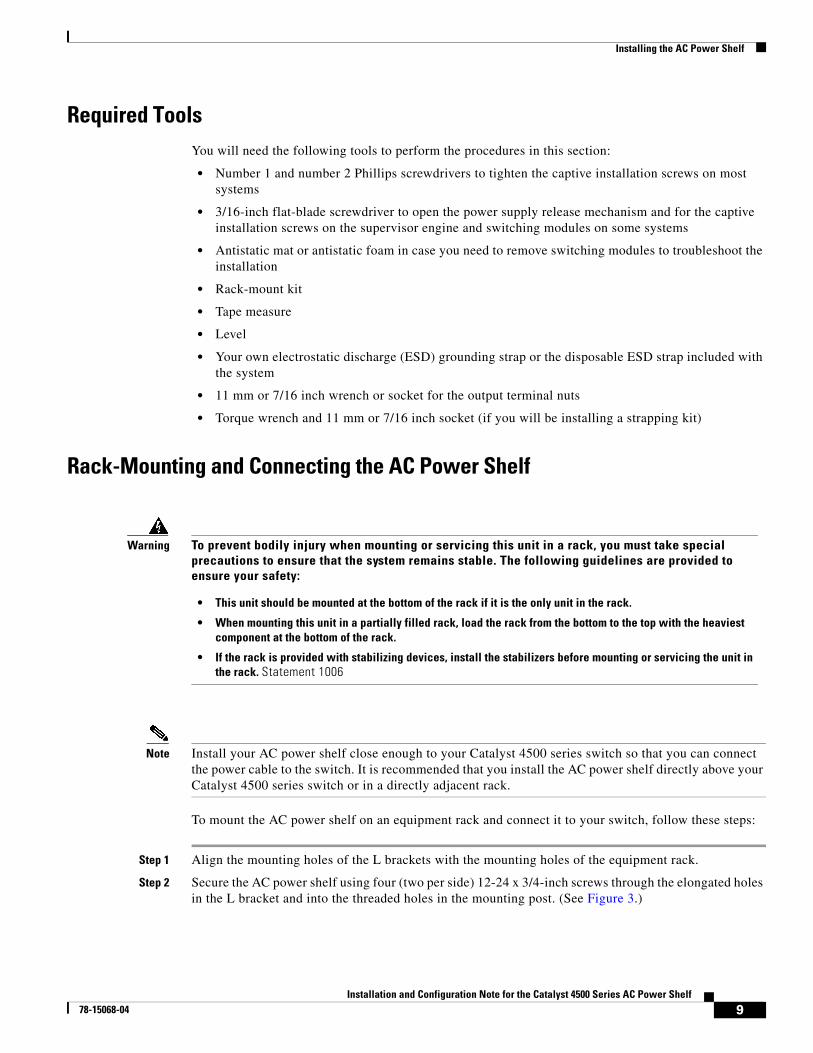
Step 1 Align the mounting holes of the L brackets with the mounting holes of the equipment rack.
Step 2 Secure the AC power shelf using four (two per side) 12-24 x 3/4-inch screws through the elongated holes in the L bracket and into the threaded holes in the mounting post. (See Figure 3.)
Warning To prevent bodily injury when mounting or servicing this unit in a rack, you must take special precautions to ensure that the system remains stable. The following guidelines are provided to ensure your safety:
• This unit should be mounted at the bottom of the rack if it is the only unit in the rack.
• When mounting this unit in a partially filled rack, load the rack from the bottom to the top with the heaviest component at the bottom of the rack.
• If the rack is provided with stabilizing devices, install the stabilizers before mounting or servicing the unit in the rack. Statement 1006
9Installation and Configuration Note for the Catalyst 4500 Series AC Power Shelf
78-15068-04
Installing the AC Power Shelf
Figure 3 Mounting the AC Power Shelf on the Rack
Step 3 Using a tape measure and a level, ensure that the AC power shelf is mounted straight and level.
Step 4 Remove the spacer bar.
Step 5 If installing a second shelf in parallel, refer to the “Installing a Second Shelf” section on page 15.
Step 6 Make sure that the power switch on the output panel is off.
Step 7 Using the CAB-4502-DC-2M or CAB-4502-DC-60CM cable set, connect the ground and power terminals on the shelf to the DC input terminals on the switch.
Step 8 Install the service access cover (WS-X4500-PS01) over the DC terminals on the power shelf as described in the following sub steps:
a. Insert the tabs on the service access cover into the slots to the left of the terminals.
b. Bend the service access cover around the terminal block, allowing the corners to poke through the slots on the cover.
7944
6Spacer bar
10Installation and Configuration Note for the Catalyst 4500 Series AC Power Shelf
78-15068-04

Installing the AC Power Shelf
Figure 4 Installing the Service Access Cover
c. Insert the tabs on the front of the service access cover into the slots to the right of the terminals.
Caution Turn off the Catalyst 4500 series switch and unplug the power cord or cords providing AC input power before removing or replacing the service access cover.
Warning This product must be connected to a power-over-ethernet (PoE) IEEE 802.3af compliant power source or an IEC60950 compliant limited power source. Statement 353
Step 9 Connect the RS-485 cable (straight-through CAT5 cable commonly used in Ethernet connections) from an RJ-45 connector on the AC power shelf output panel to the RJ-45 connector on the DC-input power supply in your Catalyst 4500 series switch. (See Figure 5.)
(+)
(-)
(+)
(-)
(+)
(-)
1376
30
11Installation and Configuration Note for the Catalyst 4500 Series AC Power Shelf
78-15068-04

Installing the AC Power Shelf
Figure 5 Connecting the RJ-485 Cable
Step 10 Install the power supplies. Refer to the “Installing a Power Supply” section on page 12.
Step 11 Power on the power switch on the AC power shelf output panel.
Installing a Power SupplyYou can install one or two power supplies into the AC power shelf. There are two slots to the right of the output panel as shown in Figure 1.
Note Do not install the power supplies until the shelf is mounted in the rack.
To install a power supply in an AC power shelf, follow these steps:
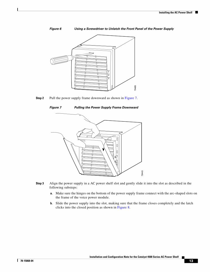
Step 1 Use a flat-blade screwdriver to unlatch the power supply frame as shown in Figure 6.
1
13
1
13
1
13
1
13
1
13
1
13
UPLINK 1UPLINK 2
ACTIVE
LINE ACTIVE LINE ACTIVE
RESETUTILIZATION
STATUS
WS-X4515 SUPERVISOR ENGINE IV
1%100%
CONSOLE
LINKEJECT
FLASH
10/100MGT
7949
1
RS-485 cable
12Installation and Configuration Note for the Catalyst 4500 Series AC Power Shelf
78-15068-04
Installing the AC Power Shelf
Figure 6 Using a Screwdriver to Unlatch the Front Panel of the Power Supply
Step 2 Pull the power supply frame downward as shown in Figure 7.
Figure 7 Pulling the Power Supply Frame Downward
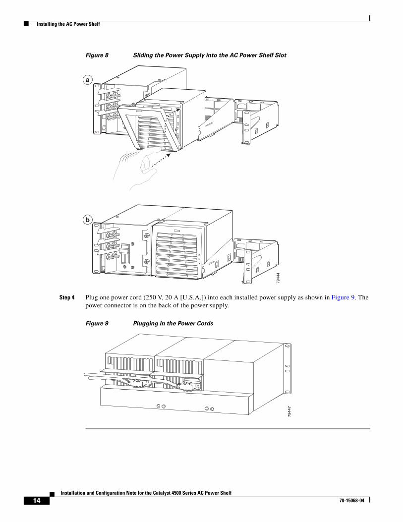
Step 3 Align the power supply in a AC power shelf slot and gently slide it into the slot as described in the following substeps:
a. Make sure the hinges on the bottom of the power supply frame connect with the arc-shaped slots on the frame of the voice power module.
b. Slide the power supply into the slot, making sure that the frame closes completely and the latch clicks into the closed position as shown in Figure 8.
AC OK
DC OK
FAULT
7948
5
7944
3
13Installation and Configuration Note for the Catalyst 4500 Series AC Power Shelf
78-15068-04
Installing the AC Power Shelf
Figure 8 Sliding the Power Supply into the AC Power Shelf Slot
Step 4 Plug one power cord (250 V, 20 A [U.S.A.]) into each installed power supply as shown in Figure 9. The power connector is on the back of the power supply.
Figure 9 Plugging in the Power Cords
7944
4
a
b
7944
7
14Installation and Configuration Note for the Catalyst 4500 Series AC Power Shelf
78-15068-04

Installing the AC Power Shelf
Installing a Second ShelfTwo voice power shelves can be connected in parallel to provide power to a Catalyst 4500 series switch. This will require a strapping kit, which can be ordered separately. To connect the shelves, follow these steps:
Step 1 Install the first shelf as described in Steps 1-4 of the “Rack-Mounting and Connecting the AC Power Shelf” section on page 9.
Step 2 If the power supplies are already installed in the first shelf, disconnect the AC power cord from each power supply or remove the power supplies from the shelf. Turning the power supply off does not disable power from the power terminals.
Warning This unit might have more than one power supply connection. All connections must be removed to de-energize the unit. Statement 1028
Step 3 Using a pair of pliers, remove the breakaway tab on the top of the output panel of the AC power shelf you just installed, and remove the breakaway tab on the bottom of the output panel of the secondary AC power shelf.
Figure 10 Locating the Breakaway Tabs
Step 4 Install the second shelf in the rack. Do not leave a gap between the shelves, install the second shelf directly on top of the first.
Step 5 Remove the shelf paralleling cover from both shelves using a Phillips screwdriver.
Step 6 Remove the nuts on the power terminals using an 11-millimeter or 7/16-inch wrench.
Step 7 Attach the strapping kit tabs to the power terminals.
9101
3Shelf parallelingcover
Bottom break away tab
Top break away tabSignal receptacle
Powerterminals
15Installation and Configuration Note for the Catalyst 4500 Series AC Power Shelf
78-15068-04

Installing the AC Power Shelf
Figure 11 Attaching the Strapping Kit
Step 8 Replace and tighten down the nuts removed in Step 5. Do not tighten more than 65 inch pounds (7 Newton meters).
Step 9 Connect the wires attached to the strapping assembly to the signalling ports on both shelves.
Warning This product must be connected to a power-over-ethernet (PoE) IEEE 802.3af compliant power source or an IEC60950 compliant limited power source. Statement 353
Step 10 Replace the shelf paralleling covers on both shelves.
Step 11 Attach the current and ground connectors as described in Step 6 to Step 8 of the “Installing the AC Power Shelf” section on page 7
1
13
1
13
1
13
1
13
1
13
1
13
UPLINK 1UPLINK 2
ACTIVE
LINE ACTIVE LINE ACTIVE
RESETUTILIZATION
STATUS
WS-X4515 SUPERVISOR ENGINE IV
1%100%
CONSOLE
LINKEJECT
FLASH
10/100MGT
9101
4
16Installation and Configuration Note for the Catalyst 4500 Series AC Power Shelf
78-15068-04

Specifications
Specifications
Related DocumentationFor more detailed installation and configuration information, refer to the following documentation:
• Catalyst 4000 Series Installation Guide
• Catalyst 4500 Series Installation Guide
• Catalyst 4000 Series Module Installation Guide
• Regulatory Compliance and Safety Information for the Catalyst 4500 Series Switches
• Software Configuration Guide—Catalyst 4000 Family, Catalyst 2948G, and Catalyst 2980G Switches
• Command Reference—Catalyst 4000 Family, Catalyst 2948G, and Catalyst 2980G Switches
• System Message Guide—Catalyst 6000 Family, Catalyst 5000 Family, Catalyst 4000 Family, Catalyst 2926G Series, Catalyst 2948G, and Catalyst 2980G Switches
Obtaining Documentation and Submitting a Service RequestFor information on obtaining documentation, submitting a service request, and gathering additional information, see the monthly What’s New in Cisco Product Documentation, which also lists all new and revised Cisco technical documentation, at:
http://www.cisco.com/en/US/docs/general/whatsnew/whatsnew.html
Table 1 AC Power Shelf Specifications
Item Specification
AC-input type Autoranging input with power factor corrector
AC-input voltage 200 to 240 VAC (±10% for full range)
AC-input current per power supply 15 A maximum at 200 VAC
AC-input frequency 50/60 Hz (nominal) (±3% for full range)
Output capacity per power supply 2600 W maximum
Output holdup time 20 ms minimum
Power shelf weight 41.9 lb (19 kg)
Power shelf dimensions height 5.13 in. (130 mm)width 17.4 in. (423 mm)length 12 in. (304 mm)
Power supply weight 9.4 lbs (4.3 kg)
Power supply dimensions height 5.13 in. (130 mm)width 5.75 in. (146.1 mm) length 10.77 in. (273.6 mm)
17Installation and Configuration Note for the Catalyst 4500 Series AC Power Shelf
78-15068-04
Subscribe to the What’s New in Cisco Product Documentation as a Really Simple Syndication (RSS) feed and set content to be delivered directly to your desktop using a reader application. The RSS feeds are a free service and Cisco currently supports RSS version 2.0.
CCSP, CCVP, the Cisco Square Bridge logo, Follow Me Browsing, and StackWise are trademarks of Cisco Systems, Inc.; Changing the Way We Work, Live, Play, and Learn, and iQuick Study are service marks of Cisco Systems, Inc.; and Access Registrar, Aironet, ASIST, BPX, Catalyst, CCDA, CCDP, CCIE, CCIP, CCNA, CCNP, Cisco, the Cisco Certified Internetwork Expert logo, Cisco IOS, Cisco Press, Cisco Systems, Cisco Systems Capital, the Cisco Systems logo, Cisco Unity, Empowering the Internet Generation, Enterprise/Solver, EtherChannel, EtherFast, EtherSwitch, Fast Step, FormShare, GigaDrive, GigaStack, HomeLink, Internet Quotient, IOS, IP/TV, iQ Expertise, the iQ logo, iQ Net Readiness Scorecard, LightStream, Linksys, MeetingPlace, MGX, the Networkers logo, Networking Academy, Network Registrar, Packet, PIX, Post-Routing, Pre-Routing, ProConnect, RateMUX, ScriptShare, SlideCast, SMARTnet, StrataView Plus, TeleRouter, The Fastest Way to Increase Your Internet Quotient, and TransPath are registered trademarks of Cisco Systems, Inc. and/or its affiliates in the United States and certain other countries.
All other trademarks mentioned in this document or Website are the property of their respective owners. The use of the word partner does not imply a partnership relationship between Cisco and any other company. (0502R)
Copyright © 2004–2005 Cisco Systems, Inc. All rights reserved.
18Installation and Configuration Note for the Catalyst 4500 Series AC Power Shelf
78-15068-04