installation and maintenance manual gpl z10000gpl z10000 – installation and maintenance manual 2 ....
TRANSCRIPT
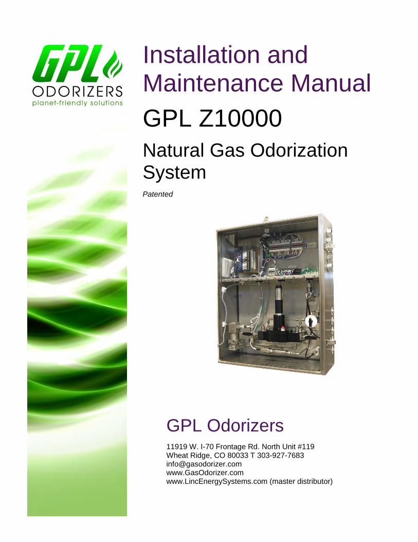
GPL Odorizers 11919 W. I-70 Frontage Rd. North Unit #119 Wheat Ridge, CO 80033 T 303-927-7683 [email protected] www.GasOdorizer.com www.LincEnergySystems.com (master distributor)
Installation and Maintenance Manual
GPL Z10000
Natural Gas Odorization System Patented
GPL Z10000 – Installation and Maintenance Manual
2
Thank you for your purchase of the GPL Z1000 Natural Gas Odorization System. In the pages to follow
you will find the Installation and Maintenance manual for this product.
Please understand that failing to adhere to these instructions may result in the void of warranty,
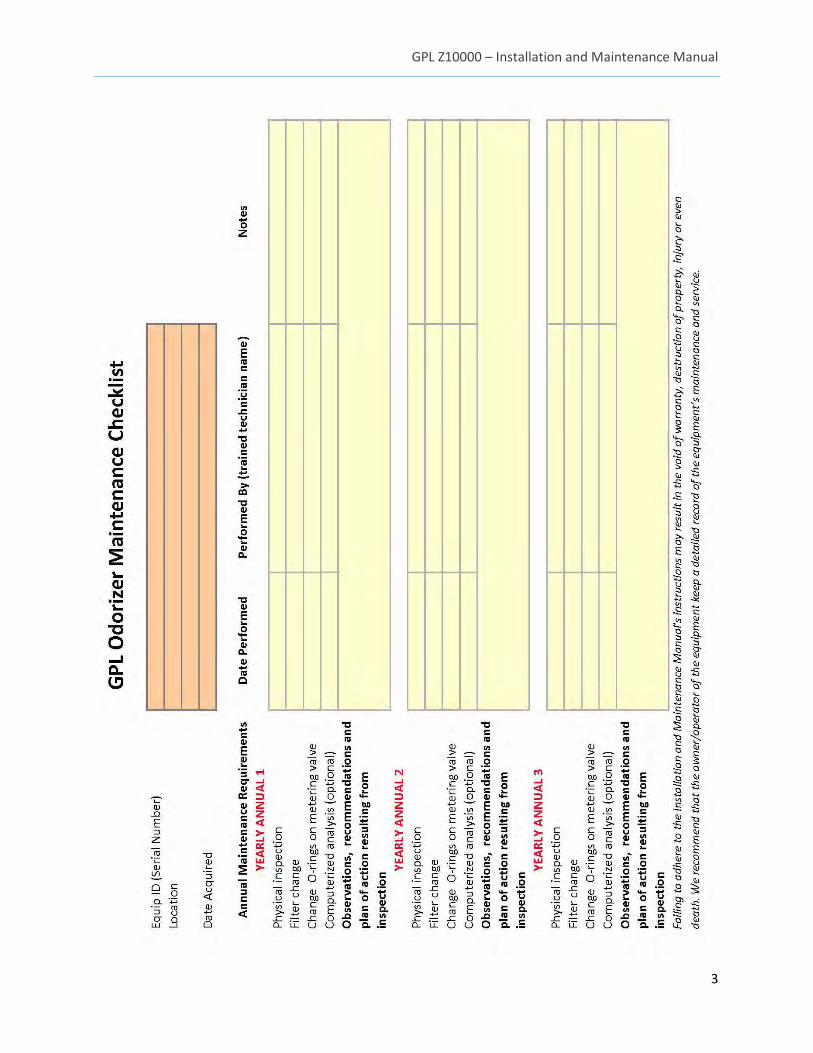
destruction of property, injury or even death. For your convenience, we have included a checklist on the
following page to document the required annual maintenance for this unit.
If you are interested in learning more about our GPL Odorizers Maintenance Program to ensure that
your unit remains functioning correctly, please call us today at (303) 927-7683. Our service contracts are
a convenient and cost-effective way to protect your warranty coverage as well as your property.
Thank you for your trust in our products.
Brian Cox
General Manager
GPL Odorizers LLC
(303) 927-7683
GPL Odorizers LLC
11919 W. I-70 Frontage Rd. North Unit #119
Wheat Ridge, Colorado 80033
GPL Z10000 – Installation and Maintenance Manual
3
GPL Z10000 – Installation and Maintenance Manual
4
Do not install, maintain, or operate this equipment without reading, understanding and following
the proper GPL Odorizers instructions. Otherwise, injury or damage or both may result.
Copyright © 2015 by GPL Odorizers LLC. All rights reserved.
This document contains proprietary information. No part of this material may be photocopied or reproduced without the
prior written consent of GPL Odorizers.
Limit of Liability
GPL Odorizers, its employees, agents, and the authors and contributors to this document specifically disclaim all liabilities and warranties, express or implied (including warranties of merchantability and fitness for a particular purpose), for the accuracy, currency, completeness, and/or reliability of the information contained herein and/or for the fitness for any particular use and/or for the performance of any material and/or equipment selected in whole or part with the user of/or in reliance on information contained herein. T h e selection of materials and equipment is at the sole risk of the user of this publication.
Note The information contained in this document is subject to change without notice.
GPL Z10000 – Installation and Maintenance Manual
5
Contents Safety Information ......................................................................................................................................... 7
General Safety Precautions ........................................................................................................................... 7
Warning Labels .............................................................................................................................................. 8
1. Specifications ........................................................................................................................................ 9
2. Overview ............................................................................................................................................. 10
2.1 Principles of Operation ..................................................................................................................... 10
2.2 Continuous Mode ............................................................................................................................. 10
2.3 Batch Mode ....................................................................................................................................... 10
2.4 System Components ......................................................................................................................... 10
2.4.1 GPL Z10000 Injector .................................................................................................................. 11
2.4.2 System Controller ...................................................................................................................... 11
2.4.3 Odorant Storage Vessel............................................................................................................. 12
3. Installation .............................................................................................................................................. 12
3.1 Site Requirements ............................................................................................................................. 12
3.1.1 Unit Location ............................................................................................................................. 12
3.1.2 Blanket Gas................................................................................................................................ 12
3.1.3 Electrical Power ........................................................................................................................ 13
3.2 Equipment and Tools ........................................................................................................................ 13
3.3 Tubing ............................................................................................................................................... 13
3.4 Wiring ................................................................................................................................................ 13
3.4.1 Electrical Connections ............................................................................................................... 13
3.4.2 Wiring Termination ................................................................................................................... 13
3.4.3 Flow Signal and Level Gauge Signal .......................................................................................... 14
3.4.4 Modbus RS-485 Wiring ............................................................................................................. 14
3.4.5 I/O Signal Verification ............................................................................................................... 14
3.4.6 External HMI (optional) ............................................................................................................. 15
3.5 Leak Testing....................................................................................................................................... 16
3.6 Unit Configuration............................................................................................................................. 16
3.6.1 Remote Configuration ............................................................................................................... 16
3.6.2 TechView ................................................................................................................................... 17
3.6.3 External HMI.............................................................................................................................. 17
GPL Z10000 – Installation and Maintenance Manual
6
3.7 Warm Start / Hydraulic Bleed ........................................................................................................... 17
4. Mechanical Overview .............................................................................................................................. 18
4.1 Solenoid Isolation Valve .................................................................................................................... 18
4.2 Positive Displacement Flow Meter ................................................................................................... 19
4.3 Hydraulic Pump Assembly ................................................................................................................. 19
4.4 Bellows Capsules ............................................................................................................................... 19
4.5 Pressure Switch ................................................................................................................................. 19
4.7 Control Boards .................................................................................................................................. 20
5. Hydraulic Pump Maintenance ................................................................................................................. 20
5.1 Maintenance cycle ............................................................................................................................ 21
5.1.1 Pump Removal .......................................................................................................................... 21
5.1.2 Piston Seal Service..................................................................................................................... 21
5.2 Pump Odorant Purge ........................................................................................................................ 22
6. Recommended Spare Parts ..................................................................................................................... 23
7. Accessories .............................................................................................................................................. 23
8. Standard Warranty .................................................................................................................................. 23
9. Factory Assistance ................................................................................................................................... 26
10. Drawings ............................................................................................................................................... 26
GPL Z10000 – Installation and Maintenance Manual
7
Safety Information Please read the entire manual before attempting to unpack, set up or operate this product. Pay careful
attention to all Warnings, Cautions, and Notes. Failure to do so could result in serious personal injury
and equipment damage.
Use of Hazard Information
If multiple hazards exist, the signal word corresponding to the greatest hazard shall be used.
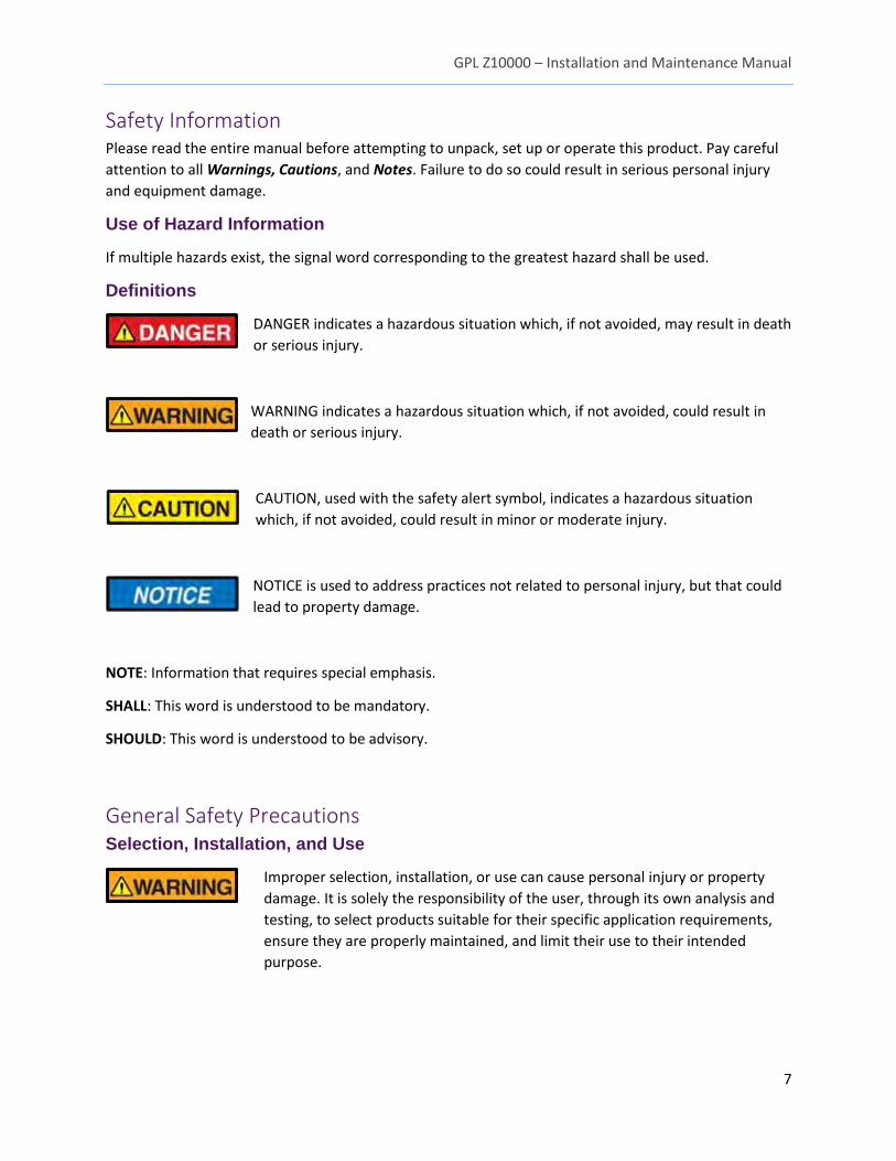
Definitions
DANGER indicates a hazardous situation which, if not avoided, may result in death
or serious injury.
WARNING indicates a hazardous situation which, if not avoided, could result in
death or serious injury.
CAUTION, used with the safety alert symbol, indicates a hazardous situation
which, if not avoided, could result in minor or moderate injury.
NOTICE is used to address practices not related to personal injury, but that could
lead to property damage.
NOTE: Information that requires special emphasis.
SHALL: This word is understood to be mandatory.
SHOULD: This word is understood to be advisory.
General Safety Precautions Selection, Installation, and Use
Improper selection, installation, or use can cause personal injury or property
damage. It is solely the responsibility of the user, through its own analysis and
testing, to select products suitable for their specific application requirements,
ensure they are properly maintained, and limit their use to their intended
purpose.
GPL Z10000 – Installation and Maintenance Manual
8
Follow proper local, state and federal regulations for proper installation and
operational requirements.
Always use caution and common sense when working with any chemical. Read
the product label and MSDS carefully and follow the instructions exactly.
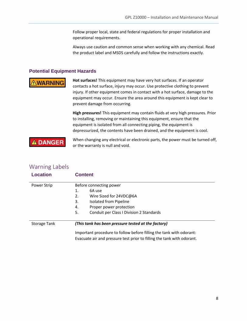
Potential Equipment Hazards
Hot surfaces! This equipment may have very hot surfaces. If an operator
contacts a hot surface, injury may occur. Use protective clothing to prevent
injury. If other equipment comes in contact with a hot surface, damage to the
equipment may occur. Ensure the area around this equipment is kept clear to
prevent damage from occurring.
High pressures! This equipment may contain fluids at very high pressures. Prior
to installing, removing or maintaining this equipment, ensure that the
equipment is isolated from all connecting piping, the equipment is
depressurized, the contents have been drained, and the equipment is cool.
When changing any electrical or electronic parts, the power must be turned off,
or the warranty is null and void.
Warning Labels Location Content
Power Strip Before connecting power 1. 6A use 2. Wire Sized for 24VDC@6A 3. Isolated from Pipeline 4. Proper power protection 5. Conduit per Class I Division 2 Standards
Storage Tank (This tank has been pressure tested at the factory)
Important procedure to follow before filling the tank with odorant:
Evacuate air and pressure test prior to filling the tank with odorant.
GPL Z10000 – Installation and Maintenance Manual
9
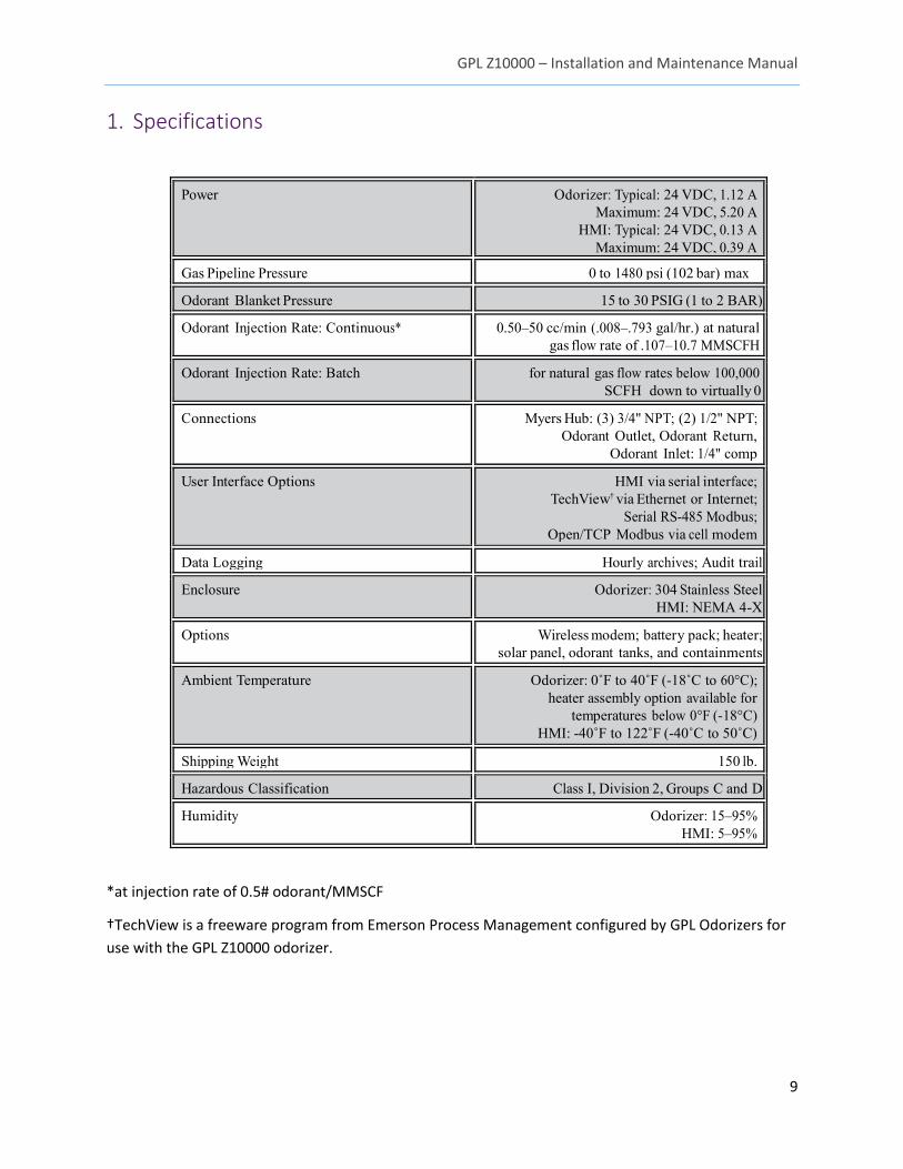
1. Specifications
Power Odorizer: Typical: 24 VDC, 1.12 A Maximum: 24 VDC, 5.20 A
HMI: Typical: 24 VDC, 0.13 A Maximum: 24 VDC, 0.39 A
Gas Pipeline Pressure 0 to 1480 psi (102 bar) max
Odorant Blanket Pressure 15 to 30 PSIG (1 to 2 BAR)
Odorant Injection Rate: Continuous* 0.50–50 cc/min (.008–.793 gal/hr.) at natural gas flow rate of .107–10.7 MMSCFH
Odorant Injection Rate: Batch for natural gas flow rates below 100,000 SCFH down to virtually 0
Connections Myers Hub: (3) 3/4" NPT; (2) 1/2" NPT; Odorant Outlet, Odorant Return,
Odorant Inlet: 1/4" comp
User Interface Options HMI via serial interface; TechView† via Ethernet or Internet;
Serial RS-485 Modbus; Open/TCP Modbus via cell modem
Data Logging Hourly archives; Audit trail
Enclosure Odorizer: 304 Stainless Steel HMI: NEMA 4-X
Options Wireless modem; battery pack; heater; solar panel, odorant tanks, and containments
Ambient Temperature Odorizer: 0˚F to 40˚F (-18˚C to 60°C); heater assembly option available for
temperatures below 0°F (-18°C) HMI: -40˚F to 122˚F (-40˚C to 50˚C)
Shipping Weight 150 lb.
Hazardous Classification Class I, Division 2, Groups C and D
Humidity Odorizer: 15–95% HMI: 5–95%
*at injection rate of 0.5# odorant/MMSCF
†TechView is a freeware program from Emerson Process Management configured by GPL Odorizers for
use with the GPL Z10000 odorizer.
GPL Z10000 – Installation and Maintenance Manual
10
2. Overview The GPL Z10000 Natural Gas Odorization System is a feature-rich, complete odorization package that
avoids the operational and functional complexities associated with other odorizers or the odorization
process. Every action is intuitive and predictable. The GPL Z10000 is a proven system, working reliably in
some of the most sensitive areas imaginable, including major cities that experience blizzard conditions
year after year. Remote locations are also accommodated as virtually everything can be taken care of via
communications features.
2.1 Principles of Operation
The GPL Z10000 automatically calculates and dispenses measured doses of odorant into natural gas
pipelines proportional to the gas flow rate.
1. An odorant storage vessel is pressurized to about 25 psi. An upstream regulator or nitrogen
source is commonly used.
2. Odorant moves from the vessel probe through the filter to the isolation valve.
3. The controller simultaneously sends pump on command and isolation valve open command
which allows the odorant to flow and get pumped through the GPL Z10000 system into the
pipeline.
4. If the controller needs to stop odorant injection into the pipeline, it simultaneously sends
pump off and isolation valve close command.
5. As the pump operates, a flow meter measures the odorant flow rate.
6. The measured flow rate is communicated to the controller, and the pump speed is adjusted
accordingly.
7. The system controller interfaces with the flow meter, gas flow information, local interface,
remote interface, etc., to maintain a constant odorant injection proportional to the gas flow
rate.
2.2 Continuous Mode
The continuous mode provides a constant flow of odorant into the stream at appropriate
proportions. Continuous mode is used for gas flow rates higher than 100 MSCFH.
2.3 Batch Mode
Batch mode periodically provides a small, metered dose of odorant, then shuts until a sufficient
volume of gas has flowed to justify another batch to achieve desired injection rates. Batch mode is
used for gas flow rates lower than 100 MSCFH.
2.4 System Components
There are three main elements to the GPL Z10000 Natural Gas Odorization System:
GPL Z10000 Injector
System controller
Odorant storage vessel
GPL Z10000 – Installation and Maintenance Manual
11
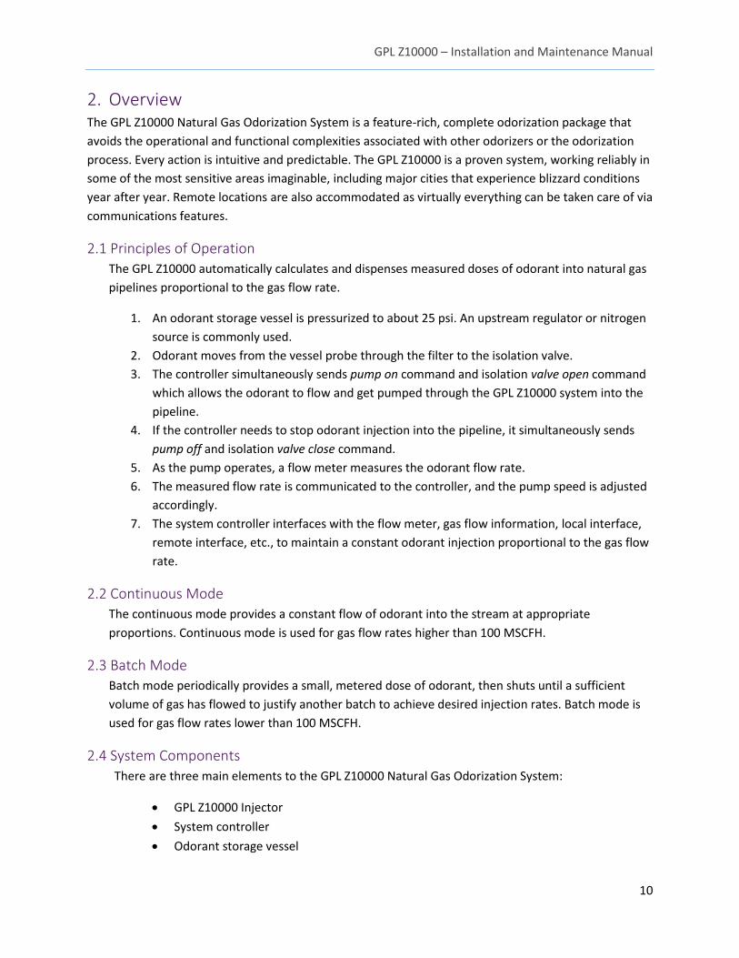
2.4.1 GPL Z10000 Injector
2.4.2 System Controller
The System Controller interfaces with the GPL Z10000 injector, precision odorant flow measurement
and gas flow information, local interface, remote interface, etc., to maintain a constant odorant
injection proportional to the gas flow rate.
GPL Z10000 – Installation and Maintenance Manual
12
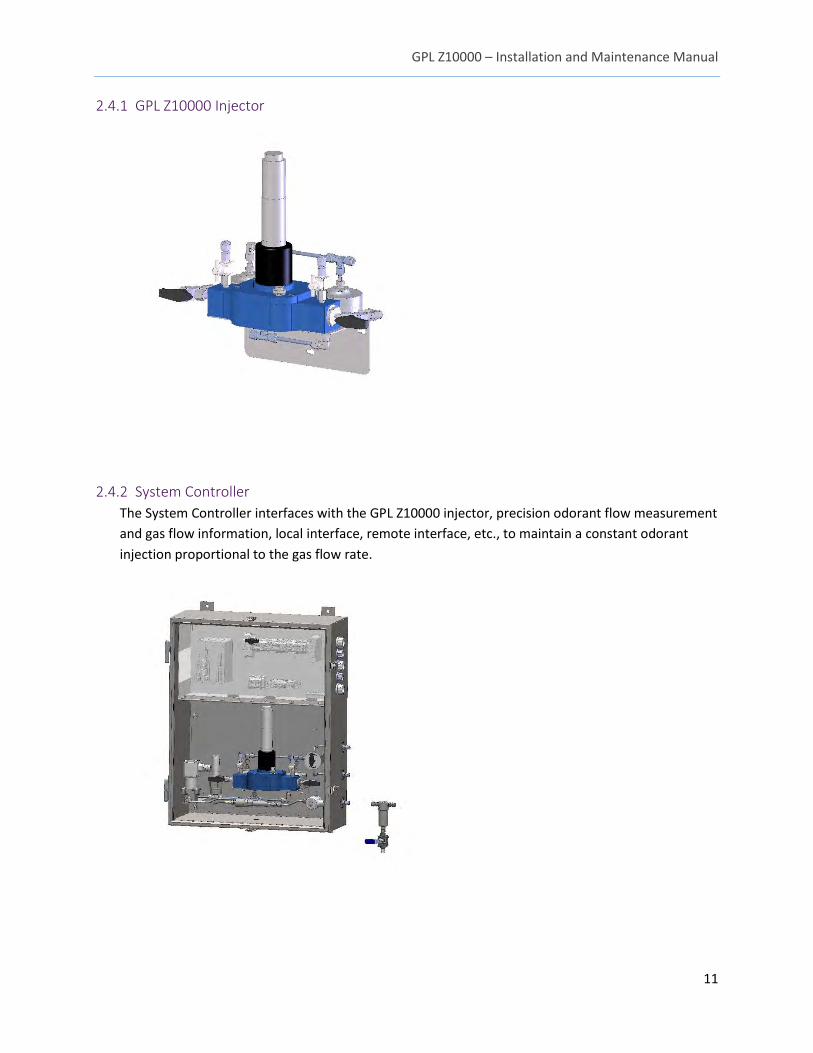
2.4.3 Odorant Storage Vessel
The blanket pressure of the odorant storage vessel should be kept low—less than 30 psi. Regulated
pipeline gas or nitrogen is commonly used. Odorant moves from the vessel probe through the filter
to the isolation valve (that automatically closes with loss of pipeline pressure).
3. Installation Qualified personnel should perform the installation by applicable state/
provincial and local codes and procedures.
3.1 Site Requirements
3.1.1 Unit Location
If possible install the GPL Z10000 at or below the odorant storage vessel. This allows further
reduction of blanket pressures on the odorant storage tank.
3.1.2 Blanket Gas
Blanket pressure on the odorant tank provides the
inlet pressure head to the pump to help prevent
cavitation
15–30 psig needed
Nitrogen or pipeline gas
Note:
The customer must supply a
pressure regulator/ relief
device on the tank.
Note:
The customer must supply a
pressure regulator/relief device
on the blanket gas port.
GPL Z10000 – Installation and Maintenance Manual
13
3.1.3 Electrical Power
Typical: 24 VDC, 1.127 Amps
Maximum: 24 VDC, 5.2 Amps
3.2 Equipment and Tools
Tools needed for installation of the GPL Z10000 include:
Hydraulic Pump Bleed Kit (GPL Odorizers P/N 6-
05488Q)
Tube Fitting Tools
Electrical Wiring Tools
3.3 Tubing
Once an appropriate location has been determined for the GPL Z10000 and the unit has been properly
mounted, install the tubing per your company’s procedures and applicable code.
3.4 Wiring
Always disconnect power before servicing connections.
Use the guidelines below to wire any necessary
connections. Please note that not every connection
described in this section is used for every site. If you have
any questions, please contact GPL Odorizers
3.4.1 Electrical Connections
1. With power off, open the enclosure and open the electronic access door.
2. Connect +24 VDC to TB-1, Terminal 1.
3. Connect -24 VDC to TB-1, Terminal 6.
4. Connect proper ground to ground bus bar located inside the enclosure.
5. Close the electronic access door.
6. Connect conduit per applicable code.
3.4.2 Wiring Termination
Alarm Output
Sends a pulse to the RTU to notify regarding an alarm state.
TB-2, Terminal 7: +, 4–28 VDC
TB-2, Terminal 6: -, 4–28 VDC
Pulse Output
Used to monitor odorant usage by sending pulses to an RTU / external counter after a set volume
Note:
A pressure switch prevents
system damage by triggering an
alarm and stopping operation of
the unit if blanket pressure
drops below recommended
value.
Note:
Field wiring used for 24VDC
input must be suitably rated.
GPL Z10000 – Installation and Maintenance Manual
14
has passed.
TB-2, Terminal 5: +, 4–28 VDC
TB-2, Terminal 6: -, 4–28 VDC
High-Speed Counter Input
Used for pulsed flow signal.
TB-2, Terminal 11: +, 4–28 VDC
TB-2, Terminal 10: –, 4–28 VDC
3.4.3 Flow Signal and Level Gauge Signal
If you are using a 4–20 mA flow signal or level gauge signal, wire the connections to the second
terminal block as follows:
Gas Flow Signal
TB-2, Terminal 12: +, 4–20 mA
TB-2, Terminal 13: -, 4–20 mA
Tank Level
TB-2, Terminal 14: +, 4–20 mA
TB-2, Terminal 13: -, 4–20 mA
3.4.4 Modbus RS-485 Wiring
Modbus RS-485 protocol is used to monitor the real-time status of the GPL Z10000 natural gas
odorizer. Wire the connections to the third terminal block as follows:
TB-3, Terminal 5: +, RS-485
TB-3, Terminal 4: -, RS-485
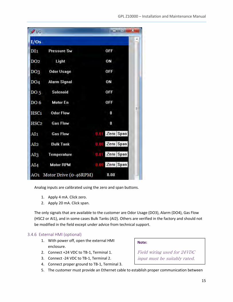
3.4.5 I/O Signal Verification
The TechView I/O page allows verification of I/O signals to the GPL Z10000. The status of DI and DO
pins can be seen and verified. See the image below for an example of the I/O screen.
Note:
Wiring the High-Speed Counter
Input to the GPL Z10000 power
strip is not recommended as
this increases the potential for
signal interference.
GPL Z10000 – Installation and Maintenance Manual
15
Analog inputs are calibrated using the zero and span buttons.
1. Apply 4 mA. Click zero.
2. Apply 20 mA. Click span.
The only signals that are available to the customer are Odor Usage (DO3), Alarm (DO4), Gas Flow
(HSC2 or AI1), and in some cases Bulk Tanks (AI2). Others are verified in the factory and should not
be modified in the field except under advice from technical support.
3.4.6 External HMI (optional)
1. With power off, open the external HMI
enclosure.
2. Connect +24 VDC to TB-1, Terminal 1.
3. Connect -24 VDC to TB-1, Terminal 2.
4. Connect proper ground to TB-1, Terminal 3.
5. The customer must provide an Ethernet cable to establish proper communication between
Note:
Field wiring used for 24VDC
input must be suitably rated.
GPL Z10000 – Installation and Maintenance Manual
16
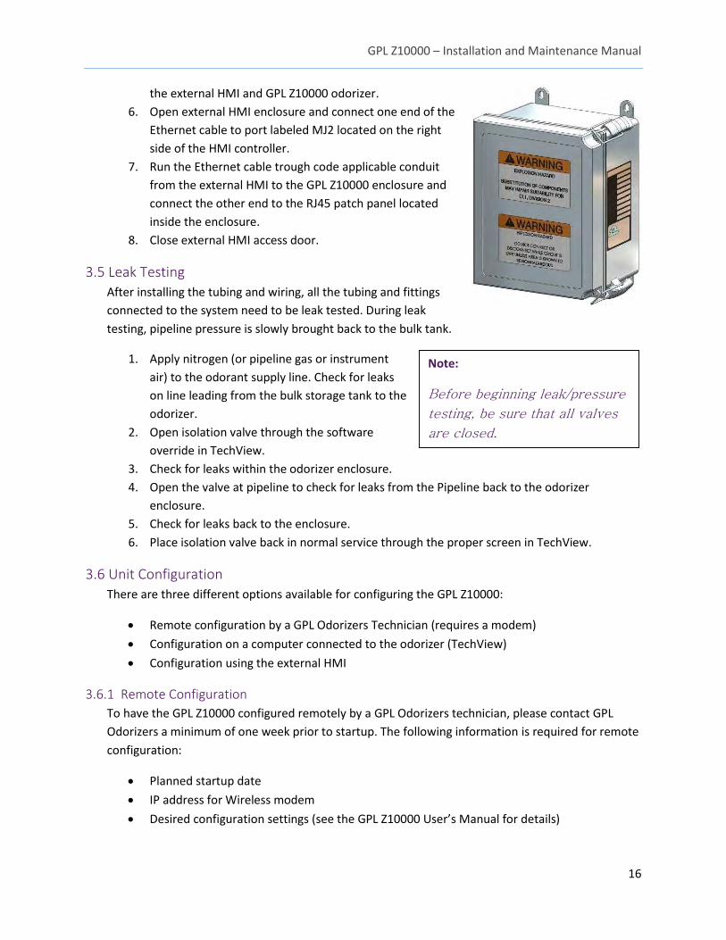
the external HMI and GPL Z10000 odorizer.
6. Open external HMI enclosure and connect one end of the
Ethernet cable to port labeled MJ2 located on the right
side of the HMI controller.
7. Run the Ethernet cable trough code applicable conduit
from the external HMI to the GPL Z10000 enclosure and
connect the other end to the RJ45 patch panel located
inside the enclosure.
8. Close external HMI access door.
3.5 Leak Testing
After installing the tubing and wiring, all the tubing and fittings
connected to the system need to be leak tested. During leak
testing, pipeline pressure is slowly brought back to the bulk tank.
1. Apply nitrogen (or pipeline gas or instrument
air) to the odorant supply line. Check for leaks
on line leading from the bulk storage tank to the
odorizer.
2. Open isolation valve through the software
override in TechView.
3. Check for leaks within the odorizer enclosure.
4. Open the valve at pipeline to check for leaks from the Pipeline back to the odorizer
enclosure.
5. Check for leaks back to the enclosure.
6. Place isolation valve back in normal service through the proper screen in TechView.
3.6 Unit Configuration
There are three different options available for configuring the GPL Z10000:
Remote configuration by a GPL Odorizers Technician (requires a modem)
Configuration on a computer connected to the odorizer (TechView)
Configuration using the external HMI
3.6.1 Remote Configuration
To have the GPL Z10000 configured remotely by a GPL Odorizers technician, please contact GPL
Odorizers a minimum of one week prior to startup. The following information is required for remote
configuration:
Planned startup date
IP address for Wireless modem
Desired configuration settings (see the GPL Z10000 User’s Manual for details)
Note:
Before beginning leak/pressure
testing, be sure that all valves
are closed.
GPL Z10000 – Installation and Maintenance Manual
17
3.6.2 TechView
Please see the GPL Z10000 User’s Manual for instructions on configuring the odorizer using
TechView.
3.6.3 External HMI
Please see the GPL Z10000 User’s Manual for instructions on configuring the odorizer using the
external HMI.
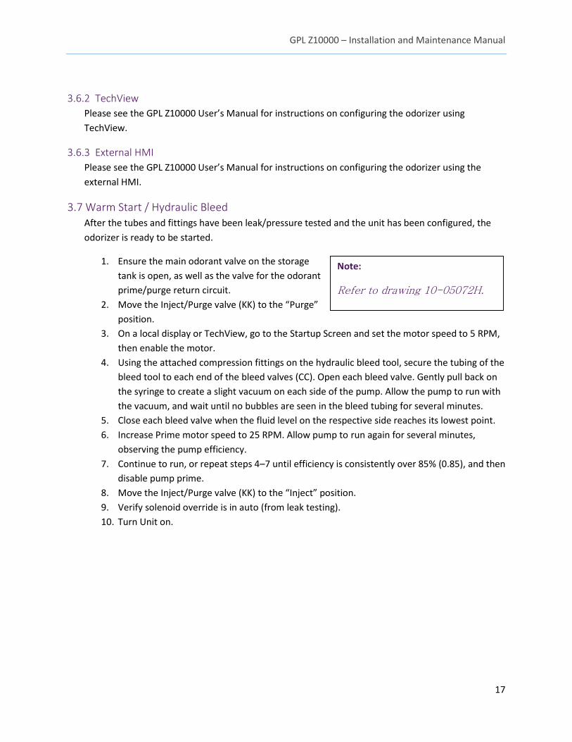
3.7 Warm Start / Hydraulic Bleed
After the tubes and fittings have been leak/pressure tested and the unit has been configured, the
odorizer is ready to be started.
1. Ensure the main odorant valve on the storage
tank is open, as well as the valve for the odorant
prime/purge return circuit.
2. Move the Inject/Purge valve (KK) to the “Purge”
position.
3. On a local display or TechView, go to the Startup Screen and set the motor speed to 5 RPM,
then enable the motor.
4. Using the attached compression fittings on the hydraulic bleed tool, secure the tubing of the
bleed tool to each end of the bleed valves (CC). Open each bleed valve. Gently pull back on
the syringe to create a slight vacuum on each side of the pump. Allow the pump to run with
the vacuum, and wait until no bubbles are seen in the bleed tubing for several minutes.
5. Close each bleed valve when the fluid level on the respective side reaches its lowest point.
6. Increase Prime motor speed to 25 RPM. Allow pump to run again for several minutes,
observing the pump efficiency.
7. Continue to run, or repeat steps 4–7 until efficiency is consistently over 85% (0.85), and then
disable pump prime.
8. Move the Inject/Purge valve (KK) to the “Inject” position.
9. Verify solenoid override is in auto (from leak testing).
10. Turn Unit on.
Note:
Refer to drawing 10-05072H.
GPL Z10000 – Installation and Maintenance Manual
18
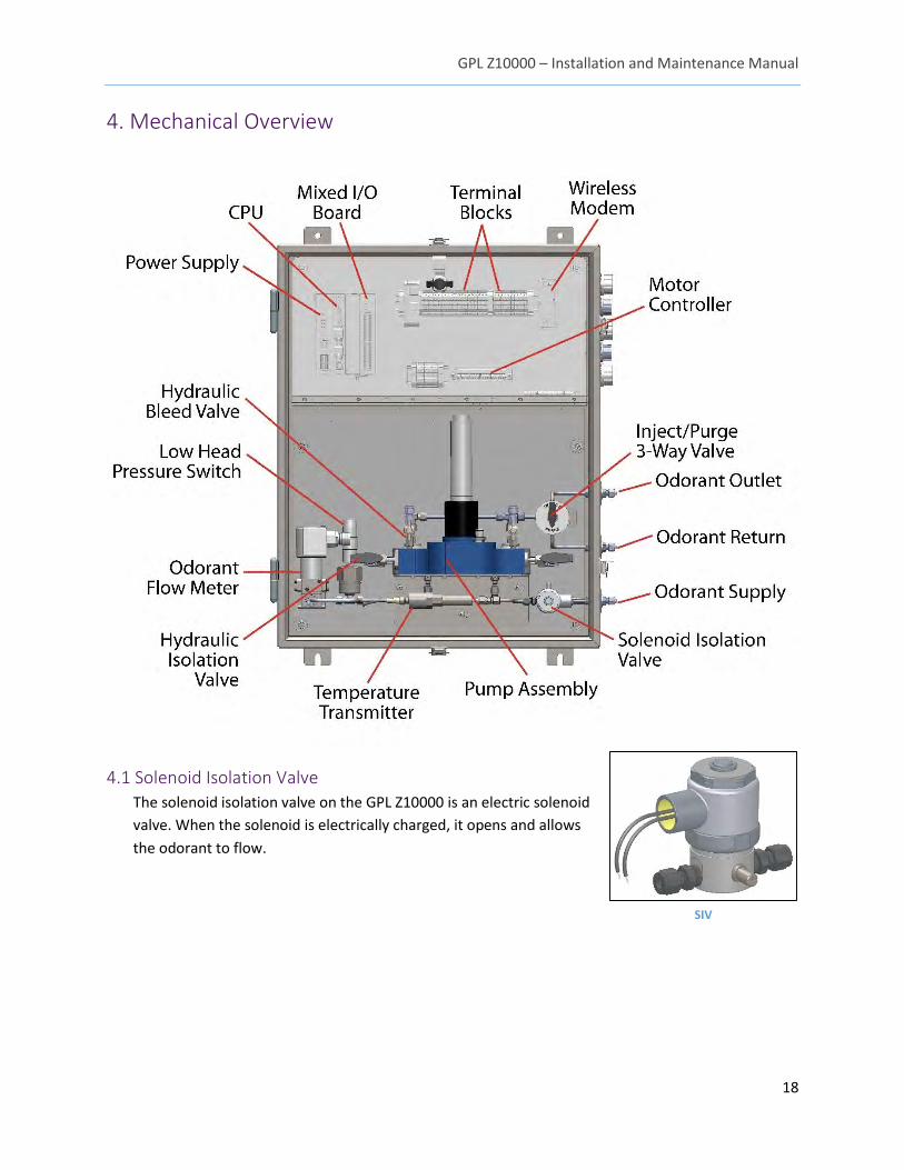
4. Mechanical Overview
4.1 Solenoid Isolation Valve
The solenoid isolation valve on the GPL Z10000 is an electric solenoid
valve. When the solenoid is electrically charged, it opens and allows
the odorant to flow.
SIV 1 SIV SIV
GPL Z10000 – Installation and Maintenance Manual
19
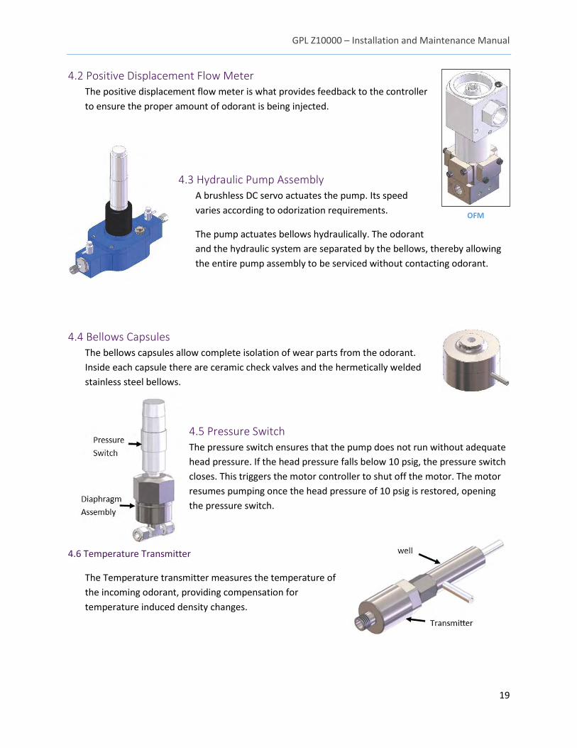
4.2 Positive Displacement Flow Meter
The positive displacement flow meter is what provides feedback to the controller
to ensure the proper amount of odorant is being injected.
4.3 Hydraulic Pump Assembly
A brushless DC servo actuates the pump. Its speed
varies according to odorization requirements.
The pump actuates bellows hydraulically. The odorant
and the hydraulic system are separated by the bellows, thereby allowing
the entire pump assembly to be serviced without contacting odorant.
4.4 Bellows Capsules
The bellows capsules allow complete isolation of wear parts from the odorant.
Inside each capsule there are ceramic check valves and the hermetically welded
stainless steel bellows.
4.5 Pressure Switch
The pressure switch ensures that the pump does not run without adequate
head pressure. If the head pressure falls below 10 psig, the pressure switch
closes. This triggers the motor controller to shut off the motor. The motor
resumes pumping once the head pressure of 10 psig is restored, opening
the pressure switch.
4.6 Temperature Transmitter
The Temperature transmitter measures the temperature of
the incoming odorant, providing compensation for
temperature induced density changes.
OFM
GPL Z10000 – Installation and Maintenance Manual
20
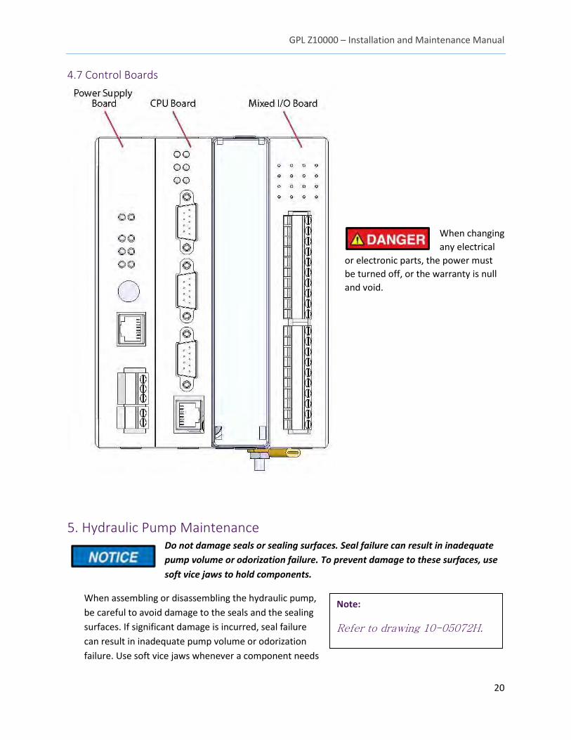
4.7 Control Boards
When changing
any electrical
or electronic parts, the power must
be turned off, or the warranty is null
and void.
5. Hydraulic Pump Maintenance Do not damage seals or sealing surfaces. Seal failure can result in inadequate
pump volume or odorization failure. To prevent damage to these surfaces, use
soft vice jaws to hold components.
When assembling or disassembling the hydraulic pump,
be careful to avoid damage to the seals and the sealing
surfaces. If significant damage is incurred, seal failure
can result in inadequate pump volume or odorization
failure. Use soft vice jaws whenever a component needs
Note:
Refer to drawing 10-05072H.
GPL Z10000 – Installation and Maintenance Manual
21
to be held, and clean and degrease all sealing surfaces before reassembly.
Unless otherwise noted, lubricate all threads with a copper grease, such as Loctite C5-A, to prevent
seizure.
Use a calcium based grease, such as JetLube 35050, on all O-rings, seals, and sealing surfaces when
assembling.
When performing maintenance, the pump should be removed from the mechatronic enclosure and
moved to a clean area.
5.1 Maintenance cycle
The hydraulic pump assembly, which includes the motor and gearbox, is designed to go without
maintenance for 3 million cycles, or 1 year, whichever comes first.
5.1.1 Pump Removal
To remove the pump from the mechatronic enclosure:
1. Ensure that the unit is turned off.
2. Open the electronic assembly door, and disconnect the wires leading from the motor/gear
box (F) to the motor controller (MM). Remove the ground wire.
3. Close the electronic assembly door and also close the two hydraulic isolation valves on
either side of the pump (AA).
4. Using an 11/16th or adjustable wrench, loosen the nuts connecting the isolation valves (AA)
to Piston chamber outlet fittings (T).
5. Loosen and remove the two #10-32 Socket Head cap screws from the bottom of the pump
(RR).
6. The pump body can now be pulled out of the mechatronic enclosure. Note that hydraulic
fluid can leak out of the pump body at this point; take care to minimize spills and drops of
the fluid.
5.1.2 Piston Seal Service
To replace the piston seals within the pump housing:
1. Using a ¼" Allen wrench, loosen and remove the 4 socket head cap screws (S) from the
pump housing lid (U).
2. The lid (U), which is bolted to the Drive shaft housing (V) and motor/gearbox (F), can now be
pulled up from the pump body. Note that the inner hydraulic chamber is filled with
hydraulic fluid and the Cam roller bearing (K) and crankshaft (X) are covered in oil. Take care
to avoid drips and spills.
3. The hydraulic fluid in the pump body can now be poured into a large bowl or container.
Dispose of the fluid in the proper manner.
4. Remove the Scotch Yoke bearing housing (J) by pulling the part straight upwards from the
body. Inspect and clean the bearing housing, and look for signs of excessive wear.
GPL Z10000 – Installation and Maintenance Manual
22
5. Remove each of the pistons (H) by pulling straight back from the cavity they are inserted in.
Take care that the pistons are not scratched or damaged during disassembly. Inspect and
clean the pistons, and look for signs of excessive wear.
6. Using a 1- 1/16" or adjustable wrench, loosen and remove the Piston Chamber outlet fittings
(T) on either side of the pump.
7. Using a 5/16" Allen wrench, loosen and remove the Hydraulic seal cartridge housings (M)
from each side of the pump body. Ensure that the O-rings that are at the end of each
housing are removed with the seal cartridges. Dispose of the used cartridges.
8. Unpackage the new Hydraulic seal cartridges and using Loctite 222, install and torque the
new housings to 5 ft. - lbs. (6.8 N-m) in each end of the pump body.
9. Reinstall the pistons (H) into each cavity, making sure to lubricate the pistons before
insertion.
10. Reinstall the Scotch Yoke bearing housing (J), making sure that each piston is reattached to
the housing.
11. Using a 1- 1/16" or adjustable wrench, install the Piston Chamber outlet fittings (T) on either
side of the pump, and torque to 1 ft-lb (1.4 N-m).
12. Fill the pump body with Hydraulic fluid #41 (6-05488R), moving the piston back and forth,
priming each chamber. This results in some hydraulic fluid being pumped out of each Piston
Chamber outlet fitting (T).
13. Reinstall the pump lid (U), which contains the crankshaft (X), cam bearing (K), and
motor/gearbox (F). Ensure the cam bearing is inside the scotch yoke bearing housing (J).
14. Align the pump lid (U), with the four holes for the ¼"-20 Socket head cap screws(S).
15. Install with Loctite 222 the 4 socket head cap screws(S), and torque to 6 ft.-lbs.
16. Move the pump assembly back into the main mechatronic enclosure.
17. Reinstall the wire leads from the motor (F) to the motor controller (MM).
18. Reinstall and tighten the two nuts from the piston chamber outlet fittings (T) to the
hydraulic isolation valves (AA).
19. Open the hydraulic isolation valves (AA).
20. Follow instructions in section 3.7 for bleeding of the hydraulics.
5.2 Pump Odorant Purge In some cases, it may be necessary to drain and purge all odorant from the GPL Z10000 assembly
and back into the bulk tank.
Do not send high-pressure purge gas (either nitrogen or pipeline gas) through
the GPL Z10000. The positive displacement flow meter can be damaged if higher
pressures are used.
1. Ensure the GPL Z10000 is in standby mode and that the startup page with isolation valve
override is open.
2. Turn the purge/injection 3-way valve (KK) to the purge position.
3. Close the odorant supply valve on the bulk storage tank.
GPL Z10000 – Installation and Maintenance Manual
23
4. Shut the blanket gas valve on the bulk storage tank.
5. Open the odorant prime/purge return valve on the bulk storage tank.
6. Change the blanket gas regulator to 5–10 psig over the current tank pressure, if blanket gas
is used to purge. (If an external source is used, make sure it is regulated to 5–10 psig over
the current blanket pressure, and tube the source after the odorant supply valve on the bulk
tank.)
7. Open the odorant line purge valve.
8. Override the solenoid valve on the startup page. This allows the gas in the odorant line
purge valve to force all odorant in the GPL Z10000 out and back into the bulk storage tank.
9. Wait several minutes to ensure all odorant has been purged into the storage tank.
10. Close the odorant line purge valve.
11. Close the odorant prime/purge return valve on the bulk storage tank.
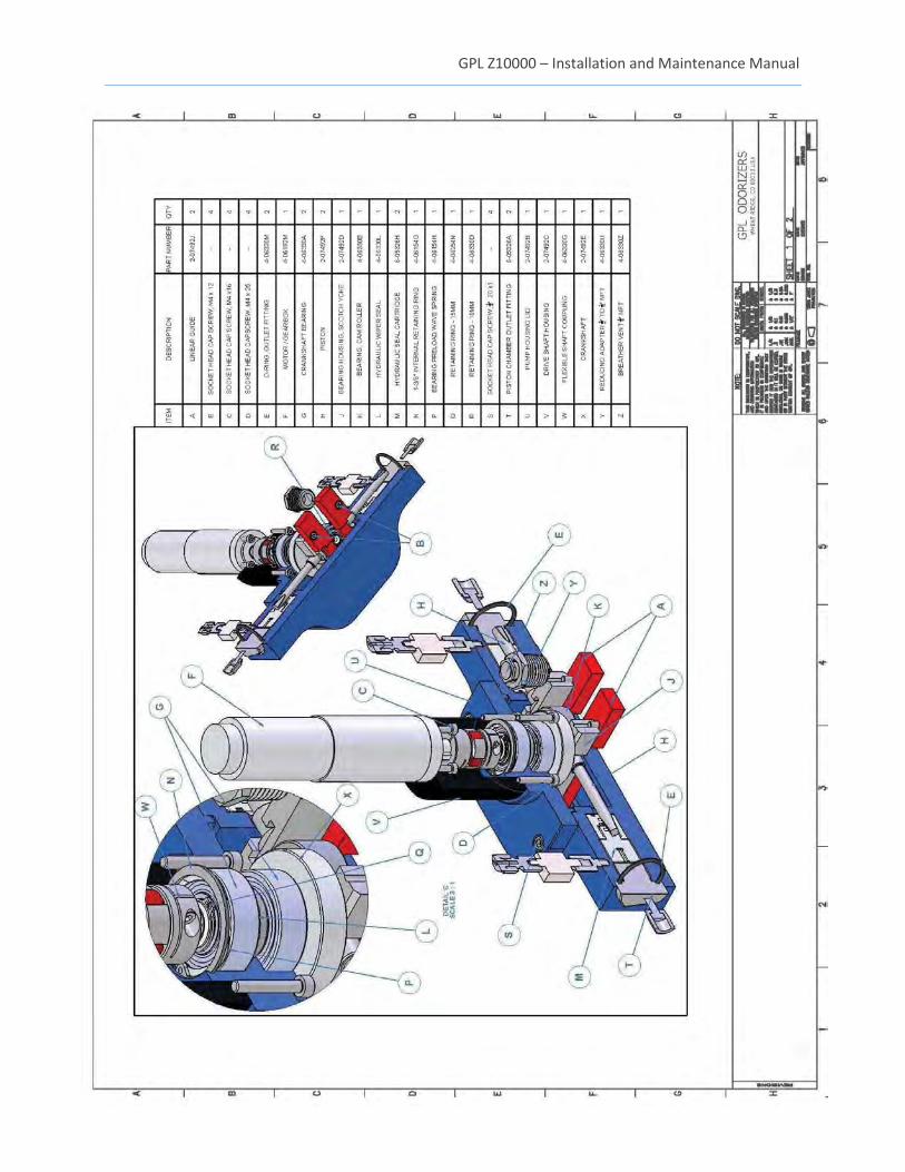
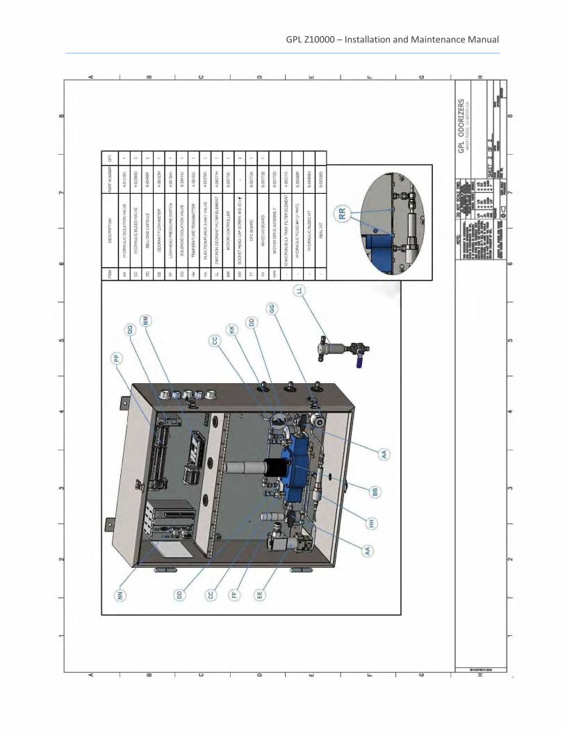
6. Recommended Spare Parts Refer to drawing 10-05072H at the end of this manual for the spare parts list.
7. Accessories
* Note: For heater accessory customer to provide fused disconnect sized in accordance with local code.
8. Standard Warranty GPL Odorizers (“Seller”) warrants products manufactured by it and supplied hereunder to be free from
defects in workmanship and, to the extent materials are selected by Seller, to be free from defects in
materials, in each case for a period as defined in the table below:
Product Line Warranty Period
GPL Odorizers Eighteen months from date of shipment or twelve
months from startup (whichever occurs first)
Odorizer Bellows Pump Module Eighteen months from date of shipment
If within such period any such products shall be proved to Seller’s satisfaction to be defective, such
products shall be repaired or replaced at Seller’s option. Seller’s sole obligation and Buyer’s exclusive
Item Part Number
Heater * 6-05568E 6-05568D
Wireless Modem 6-05568C Odorant Visual Indicator 7-04733A External HMI 7-04578K
GPL Z10000 – Installation and Maintenance Manual
24
remedy hereunder shall be such repair and replacement and shall be conditioned upon Seller’s receiving
written notice of any alleged defect within 10 days after its discovery and, at Seller’s option, return of
such product to Seller, FOB GPL Odorizers’ factory or provision of evidence (e.g., photographs) of such
defect satisfactory to Seller.
Warranty Conditions & Limitations
This Warranty shall not apply to any GPL Odorizers entry product which, in the opinion of GPL Odorizers,
has been (a) altered or repaired in a manner affecting the efficiency or performance of the unit or (b)
incorrectly installed or operated or (c) damaged in shipment or (d) damaged by flood or fire or (e) if the
serial number is missing, altered or defaced.
Any materials required to be used by Seller as provided in customer specifications or instructions are
excluded from the foregoing warranty and customer assumes sole responsibility for the selection of
such materials. Customer further acknowledges and agrees that, to the extent Customer requests that
GPL Odorizers make any recommendations with respect to materials to be used in connection with
products, Seller may rely on published reference literature, that any references based on third-party
studies may not correlate directly with the end user’s intended usage or process (i.e., chemical
composition, concentrations, temperatures, etc.), and that Customer is solely responsible for the final
determination with respect to which materials are to be used in connection with the products.
EXCEPT FOR THE LIMITED WARRANTIES SET FORTH HEREIN, SELLER HEREBY DISCLAIMS ANY AND ALL
WARRANTIES AND REPRESENTATIONS (EXPRESS OR IMPLIED, ORAL OR WRITTEN), INCLUDING ANY AND
ALL IMPLIED WARRANTIES OF MERCHANTABILITY OR FITNESS FOR ANY PURPOSE WHETHER OR NOT
SELLER KNOWS, OR HAS REASON TO KNOW, HAS BEEN ADVISED, OR IS OTHERWISE IN FACT AWARE OF
ANY SUCH PURPOSE, WHETHER ALLEGED TO ARISE BY LAW, BY REASON OF CUSTOM OR USAGE IN THE
TRADE, OR BY COURSE OF DEALING OR PERFORMANCE. Without limiting the generality of the foregoing,
Seller makes no warranty regarding ability of products sold hereunder to withstand erosion or corrosion,
or regarding material compatibility of elastomers in specific services, and no warranty made hereunder
shall apply to products which have been subjected to adverse storage.
The owner shall be responsible for maintenance of his equipment. Wear or damage caused by lack of
normal maintenance or misuse of equipment shall not be considered as defective workmanship and
material.
If a part requires replacement during the warranty period, the part must be returned to GPL Odorizers
for credit or the customer will be responsible for paying for the replacement part(s).
GPL Odorizers and its subsidiaries reserve the right to make product design changes or improvements
without notice and without imposing any obligation upon itself to install these changes or
improvements on its products previously manufactured.
This warranty is for the sole benefit of the original purchaser and is not transferable unless agreed to in
writing by GPL Odorizers.
GPL Z10000 – Installation and Maintenance Manual
25
Receiving Shipments (including loss or damage by transportation)
It is the customer’s responsibility to check for missing cartons and/or sign of damage to cartons. If
found, the customer should note missing and/or damaged boxes on the delivery receipt and have a
delivery receipt signed by the representative of the transportation company. If unpacking discloses
concealed damage from rough handling, the customer should request a concealed damage inspection
from the transportation company.
The GPL Odorizers Customer Service Department will aid your organization in any claim proceeding for
shortages or damages in shipment, but it is the receiver’s responsibility to file a claim with the carrier for
damage or loss.
Liability Limitation
IN NO EVENT, WHETHER FOR BREACH OF WARRANTY OR OTHER CONTRACT BREACH, NEGLIGENCE OR
OTHER TORT, OR ON ANY STRICT LIABILITY THEORY, SHALL GPL ODORIZERS., ITS SUBSIDIARIES OR ITS
SUPPLIERS BE LIABLE FOR ANY INCIDENTAL OR CONSEQUENTIAL DAMAGES WHATSOEVER (INCLUDING
BUT NOT LIMITED TO DAMAGES FOR LOSS OF PROFITS, BUSINESS INTERRUPTION, LOSS OF
INFORMATION, OR OTHER PECUNIARY LOSS) ARISING OUT OF THE USE OF, OR INABILITY TO USE, THE
PRODUCTS, EVEN IF GPL ODORIZERS. OR ANY OF ITS SUBSIDIARIES, HAS BEEN ADVISED OF THE
POSSIBILITY OF SUCH DAMAGES.
Customer Actions for Claims on Products during the Warranty Period
1. Contact the Customer Service Department, GPL Odorizers, Wheat Ridge, CO, Telephone: 303-
927-7683, to obtain a Return Material Authorization (RMA) number.
2. You will be sent an “RMA” and a “Decontamination Statement” that is required to be filled out
and returned with the equipment.
3. The following information must appear on the outside of the package:
RMA number is marked on the outside of the box.
Decontamination Statement filled out and attached to the outside of the box.
4. Return defective equipment FREIGHT PREPAID. Collect shipments will be refused.
5. The factory will not process warranty claims until the customer has properly accomplished the
above items.
6. The GPL Odorizers factory may accept the entire claim, a part of the claim or none of the claim if
our inspection of returned parts proves the failure was for reasons other than defective material
or factory workmanship.
Important Notes:
1. GPL Odorizers will not be responsible for damage incurred during the return shipment.
2. All returns subject to inspection and a minimum $100.00 evaluation fee for any products found
not to be defective.
3. This RMA is not authorization for credit. Credits and/or replacements will be issued upon
GPL Z10000 – Installation and Maintenance Manual
26
evaluation of returned goods.
4. RMA is valid for thirty (30) days from issue date.
9. Factory Assistance GPL Odorizers manufactures environmentally-friendly odorant injection systems for natural gas and
other gases.
Please do not return any equipment before discussing your application problem with a GPL Odorizers
representative and obtaining a Return Authorization.
GPL Odorizers has a dedicated staff of trained Service Department associates to assist customers with
any problems. Please call GPL Odorizers at 303.927.7683 and request a service representative.
For other sampling applications, your GPL Odorizers representative is eager to help you. Please feel free
to call your representative or contact GPL Odorizers to discuss your application.
GPL Odorizers LLC
11919 W. I-70 Frontage Rd. North Unit #119
Wheat Ridge, Colorado 80033
Phone: 303.927.7683
E-mail: [email protected]
10. Drawings See the following two pages.
GPL Z10000 – Installation and Maintenance Manual
27
GPL Z10000 – Installation and Maintenance Manual
28