installation and maintenance manual -...
TRANSCRIPT

Electrical Treasure ▏One-Stop Supplier Of Electrical Equipment 1
KYN28-12 Series
H.V Metal Clad Switchgear
Installation and Maintenance Manual
10/09/2015

Electrical Treasure ▏One-Stop Supplier Of Electrical Equipment 2
Always Safety First In the Switch Equipment Installation Please Read
This Manual Carefully Before Use
Switch equipment can only be installed in indoor places suitable
for the operation of electric equipment. Ensure the professional
electrical personnel for installation, operation and maintenance.
Must ensure that the site electrical equipment of the join
condition and the application of the working procedures and
safety. All about switch equipment operation, the relevant
regulations to comply with the specifications.
DANGEROUS
Pay special attention to the instructions marked the danger
signs.
Don't beyond switching equipment under normal working
conditions prescribed by the technical parameters of the load.
Instruction should be placed on all related to the installation,
operation and maintenance personnel can easily get a place.
Users full-time personnel responsible for all matters that affect
job security, and properly manage the switch devices.
If this instruction is question, SZET Co.,LTD will be glad to
provide further information.

Electrical Treasure ▏One-Stop Supplier Of Electrical Equipment 3
1. General 1.1 Overview
KYN28-12 Series H.V Metal Clad Switchgear is applicable to
three-phase ac 50 (60)Hz, 3.6 ~ 12 KV single busbar and busbar
sectionalizing power system, with functions of "five prevention".
Switchgear can be configured to remove part of the vacuum circuit
breaker and components such as vacuum contactor.
1.2 Standards and Specifications
KYN28-12 Series H.V Metal Clad Switchgear meet IEC298,
GB3906, DL404 standard, etc.
Switchgear enclosure protection grade is IP4X, when the circuit
breaker room door open, remove handcart, protection grade is
IP2X.
During the installation and operation of the system, to abide by
all the relevant IEC standards and relevant national or local
safety guideline, SZET co., LTD., should also be considered to
provide relevant information.
1.3 Service Conditions
1.3.1 Normal Working Conditions
KYN28-12 Series H.V Metal Clad Switchgea normal working
conditions are as follows:

Electrical Treasure ▏One-Stop Supplier Of Electrical Equipment 4
Indoor Environment Temperature:
The highest temperature + 40 ° C
Daily average no greater than + 35 ° C
The lowest temperature - 15 ° C
Indoor Environment Humidity:
Daily average relative humidity 95% and below
Monthly average relative humidity 90% and below
Installation site altitude 1000 m and below
Seismic intensity is not more than 8 degrees
No fire and explosion danger, no serious polluted and chemical
corrosion.
1.3.2 Special Working Conditions
The special working conditions, must consult Manufacturers.
Manufacturers and users should be agreed on special working
conditions.
Have to consider the installation place higher than 1000 m
above sea level, reduce the strength of air medium effect on the
insulation level.
If the ambient temperature exceeds the limit, on the design of
bus and branch busbar compensate or limit carrying capacity.
Install ventilation inside ark of Switchgear will be conducive to

Electrical Treasure ▏One-Stop Supplier Of Electrical Equipment 5
heat dissipation.
1.3.3 Precautions
If the switchgear operation areas of high humidity, temperature
fluctuations is bigger, faster and amplitude switchgear running in
such a climate environment, there is the risk of condensation, thus
switchgear in standby and operating conditions, users should
guarantee the heater into 24 hours a day! But in the large current
operation, can not input.
2. Technical Data 2.1 Switchgear Electrical Parameters
Nominal Voltage KV 12
Rating Insulation
Level
1min Power Frequency Withstand Voltage(RMS) KV 42
Lightning Shock Compression (Peak Value) KV 75
Rated Frequency Hz 50(60)
Main Busbar Rated Current A 630,1250,1600,2000,2500,
3150,4000
Branch Busbar Crrent Rating A 630,1250,1600,2000,2500,
3150,4000*
Thermal Stability of 4 Seconds Current (RMS) KA 16,20,25,31.5,40**
Rated Dynamic Stable Current (peak value)*** KA 40,50,63,80,100
* Need to be equipped with ventilation * * 40 KA for 3 seconds * * * Transformer short-circuit capacity should be considered separately
2.2 Performance Bearing Inside Fault Arc
KYN28-12 switchgear in design has switchgear of internal arc
Electrical Treasure ▏One-Stop Supplier Of Electrical Equipment 6
fault into consideration, according to GB3906 and IEC298 has
carried on the strict test, can effectively ensure the safety of
equipment and operating personnel.
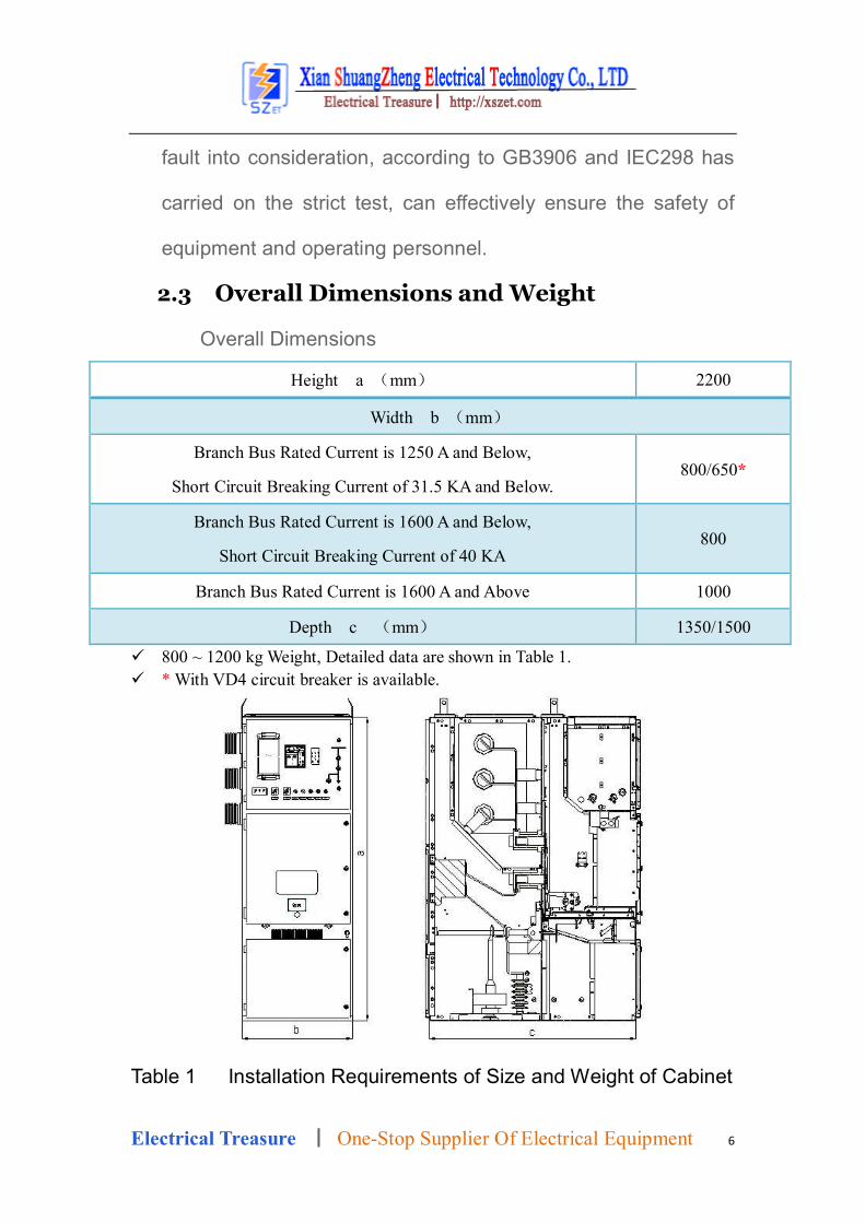
2.3 Overall Dimensions and Weight
Overall Dimensions
Height a (mm) 2200
Width b (mm)
Branch Bus Rated Current is 1250 A and Below,
Short Circuit Breaking Current of 31.5 KA and Below. 800/650*
Branch Bus Rated Current is 1600 A and Below,
Short Circuit Breaking Current of 40 KA 800
Branch Bus Rated Current is 1600 A and Above 1000
Depth c (mm) 1350/1500 800 ~ 1200 kg Weight, Detailed data are shown in Table 1. * With VD4 circuit breaker is available.
Table 1 Installation Requirements of Size and Weight of Cabinet

Electrical Treasure ▏One-Stop Supplier Of Electrical Equipment 7
Incase Equipment Movable Type Movable Type Movable Type
Depth c mm 1500 1500 1500
Width b mm 650 650 1000
Distance From the Wall mm 800 800 1200
Corridor Width * mm 1000 1100 1200
Install Channels (Indoor)
Width mm 1000 1000 1200
Length (Deep) mm 1500 1500 1500
Frame Requirements
Width mm 800 1000 1200
Height mm 2200 2200 2200
Weight (Approximation) kg 800 850 1200
Floor Bearing kg/m2 1000 1000 1000
* Depend on the most width of the switchgear.
3 Switchgear Structure 3.1 Basic Structure (FIG. 3/1)
Switchgear is composed of cabinet body and vacuum circuit
breaker handcart, this is its basic structure. switchgear and
installation of electrical components as shown in (FIG. 3/1).
Into line ark or outlet ark is basic ark scheme, and have derived
schemes, such as bus section ark or measuring tank, etc.
In addition, there are configuration stationary load switch,
vacuum contactor handcart, isolate the handcart, etc.
Install the Switchgear relying on a wall or face to face structural
details and installation equipment, contained in the order file.

Electrical Treasure ▏One-Stop Supplier Of Electrical Equipment 8
3.2 Shell and Plate
Switchgear of the shell and the clapboard is made from high
quality steel plate, has a strong resistance to oxidation and
corrosion function, and the stiffness and mechanical strength is
higher than normal low carbon steel.
The top of the three high pressure chamber is equipped with a
pressure relief plate. Appear when the internal fault, high
pressure indoor air pressure increases, because the cupboard
door has reliable seal, high pressure gas released made
pressure relief plate.
Adjacent switchgear separated by their sides, still have air
buffer layer after spell ark, can prevent the switchgear is arc
fault through melting. Low pressure chamber D assembly into
separate compartment, separated with high pressure area.
Partition to separate circuit breaker room B and C cable room,
even if the circuit breaker handcart removed (the valve will
automatically shut down) and can also prevent the operator
reach the bus room A and cable room C charged part.
Remove the bolt can remove the horizontal clapboard, facilitate
the installation of cable seal terminal.

Electrical Treasure ▏One-Stop Supplier Of Electrical Equipment 9
3.3 Small Room Inside Switchgear
3.3.1 Circuit Breaker Room (FIG. 3/1, 3/3, 3, 5, 3/6)
Circuit breaker handcart contained in the guide rail of the circuit
breaker room B, can be in the operation and test/isolation
between the two different position.
When the handcart from the run to test/isolation location moves,
valve cover automatically static contact, reverse operation is
open.
Handcart are able to operate under the condition of the switch
cupboard door close, through the observation window ON the
door can see the location of the handcart, hand car ON (circuit
breaker closing)/OFF (breaker break-brake) button, close
break-brake status indicator and energy storage/release status
indicator.
3.3.2 Handcart
Handcart can use manually move.
Framework by alloy plates assembled together, the above
circuit breakers and other equipment. A spring contact system
arm on the circuit breaker of a column, when the handcart is
inserted into the running position for electrical connection.
Handcart between switchgear, protection and control line signal,

Electrical Treasure ▏One-Stop Supplier Of Electrical Equipment 10
use one line plug connection.
Handcart just inserted switchgear/isolation position is fixed to
the experiment, at the same time also reliably connected to the
switchgear earthing system.
The position of the handcart, through the observation window or
in a low pressure chamber on the front panel handcart electrical
position indicator.
In addition to the vacuum circuit breaker, handcart can match
the vacuum contactor, isolation devices and measuring
equipment, etc
3.3.3 Busbar Room
Bus bar from one switchgear to another switchgear, through the
branch busbar and casing is fixed.
The branch of rectangle busbar with bolt connection directly to
main busbar, without any connection.
All bus and branch busbar with heat shrinkable casing cover.
Plate and the casing pipe between switchgear and switchgear
bus isolation, and be supportive.
For electric stress of switchgear, general need this support.
3.3.4 Cable Room (FIG. 3/1)

Electrical Treasure ▏One-Stop Supplier Of Electrical Equipment 11
Current transformer and earthing switch installed in the cable
room at the back. Cable room also can install lightning arrester.
L when the cable room door opened, there is enough space for
construction personnel into the rack installation cable (up 6).
Cover at the entrance of cable can use the permeability of the
base of stainless steel plate, is slotted, removable, facilitate the
site construction. Bottom plate through the primary and
secondary cable diameter changes in sealing ring opening
should be adapted to the cable, in case of small animals to
enter.
For larger humidity in cable trench, suggest using fire clay,
epoxy resin will be sealed switchgear.
3.3.5 Low Pressure Room (FIG. 3/1, 3/2)
Switchgear secondary components installed on the low
pressure room and door. Control lines trough the space, and a
cover plate, the left side of the trough to introduce and draw out
attachment between ark, the right side of the trough for laying
switchgear inside the attachment.
Low pressure room on the side panel has a line through the
hole, in order to control the power connection.
3.4 To Prevent Wrong Operation of Interlocking/Protection

Electrical Treasure ▏One-Stop Supplier Of Electrical Equipment 12
With a series of interlocking device, fundamentally to prevent a
dangerous situation and may cause serious consequences of
wrong operation, thus effectively protect the operator and
switchgear.
Interlock function is as follows:
Circuit breaker and earth switch in break-brake position,
handcart can move from the test/isolation position to the run
position.
In this state of break-brake, reverse move also ok (Machine
Interlock).
Handcart has completely in the test or run position, circuit
breaker can switch (Mechanical and Electric Interlock).
Handcart in test or run the position without the control
voltage, Circuit breaker can't switch, can only manual
break-brake (Electric Interlock).
Handcart in the run position, The line of control plug is
locked, can't pull out.
Handcart in test/isolated location or removed, Grounding
switch to switch (Machine Interlock).
Grounding switch off, Handcart can't from the test/isolation
position, move to the run position (Machine Interlock).

Electrical Treasure ▏One-Stop Supplier Of Electrical Equipment 13
In the handcart or grounding switch operating mechanism
are installed on the additional interlock,Such as locking
electromagnet,When ordering to SZET Co., LDT, request.
Figure 3/1:
KYN28-12 Into Line or Outlet Switchgear
Basic Structure Cutaway View
Separation Room
A Busbar Room B Circuit Breaker Room
C Cable Room D Low Pressure Room
Main Part
1 Bus 2 Insulator
3 The Static Contact 4 Contact Box
5 Current Transformer 6 Grounding Switch
7 Cable Termination 8 Surge Arrester
9 Zero Sequence Current Transformer 10 Circuit Breaker Handcart
10.1 Slide the Handle 10.2 To the sliding handle lock key (al)
11 Control & Protection Unit 12 Wear Casing Wall

Electrical Treasure ▏One-Stop Supplier Of Electrical Equipment 14
Main Accessories
13 Screw the Operation of the Hole 14 Cable Clamp
15.1 Cable Seal Ring 15.2 Connection Plate
16 Grounding Copper Platoon 17 The Second Plug
17.1 Locking Lever 18 Pressure Relief Plate
19 Lifting Ear 20 Transport the Car
20.1 Lock Lever 20.2 Adjust the Wheel
20.3 Guide Bar
Figure
3/3 Circuit Breaker Room Door Open,
Handcart in Test Position Figure
3/4 Circuit Breaker Handcart in the
Position to Run Into
21 Movable Door 10.3 Contact Torx Head
4 Contact Box 10.4 Contact Arm
10 Circuit Breaker Handcart

Electrical Treasure ▏One-Stop Supplier Of Electrical Equipment 15
Figure 3/5
Circuit breaker handcart Figure 3/6
After Handcart Removed, Move the Door is
Open Circuit Breaker Interior View
17 The Control Line Socket 3 The Static Contact
4 Contact Box 21 Valve
4 Transportation and Storage 4.1 Terms of Delivery
In addition to order check, good switchgear assembly, should
also comply with the corresponding IEC298, GB3906 relevant
provisions of the factory test, the correctness of the structure and
function of the correction. Bus, fasteners, accessories are separate
packing.
4.2 Packaging
The packing of the switchgear, corresponding adjustments
according to the requirement of the specific situation, such as
sailing packing or not. Maritime transport, in particular, even if it is
shipped in container, also used plastic film bag to switchgear
encapsulated, desiccant is put in the right in case of be affected
with damp be affected with damp.
4.3 Transport
Normally consist of a single switchgear transport unit,
exceptional cases, can be composed of switchgear group or

Electrical Treasure ▏One-Stop Supplier Of Electrical Equipment 16
installed back-to-back switchgear transport unit.Each
switchgear contains four lug.
Switchgear should be vertical transportation, measures
must be taken to protect the safety of personnel and equipment,
with one of the following tools to be able to do the work for
loading:
Cranes, forklift or artificial hanger.
Crane load
Rope should have enough carrying capacity, hook open
width should be≥ 30 mm
Coupling hook the rope and the Angle between the
horizontal line should stay above 60 °.
Lifting switchgear, allows for a corresponding bending lug.
4.4 Delivery and Storage Process
Switchgear arrived at the scene, the consignee has the
responsibility to (but not limited to) do the following work:
Inform my company site service engineers to join the
unpacking acceptance work.
Complete and check the arrival of the goods is damaged or
not. Switchgear certificate is correct and complete, and the
presence of the instructions. If there is any doubt, then open

Electrical Treasure ▏One-Stop Supplier Of Electrical Equipment 17
the check. If you need storage, Excessive care also add
desiccant and seal again.
Detailed records of any shortage, defects and damage in
transport, and inform the relevant authorities.
Please note that the storage process, should be placed in to
the switchgear and install material without any damage.
4.4.1 Open the Packing Cases
First of all, the roof broke open the packing cases, and then
open the side panel, around the finally removing the
switchgear and chassis coupling bolt.
Please note that the removed each socket head bolts,
should answer in a switchgear of his place, and should twist
tight.
Using four lifting lugs on the top of the cupboard, switchgear
vertical lift make it out of the chassis.
Then remove the chassis to, in the bottom of the tank into
the roll bar, reuse stick slowly move, to Then move chassis,
into the roll bar in the bottom of Switchgear, reuse stick
slowly move, moving Switchgear to install or temporary
location.
Pay attention to in the process of moving, cannot have the

Electrical Treasure ▏One-Stop Supplier Of Electrical Equipment 18
heavier impact and vibration.
4.4.2 Simple Packaging &No Packing of the Switchgear
Storage room should be dry, well ventilated.
Indoor temperature is not lower than -25 ° C
No other harmful environmental impact.
Switchgear should be upright to deposit.
Switchgear can't pile up.
Cannot remove or damage to the packaging.
Unpacked switchgear, cover loosely with plastic film to avoid
staining. Must maintain the air circulation to prevent
corrosion.
Lon inspections regularly on time, until the installation work
to begin.
4.4.3 Seaworthy Packing and Internals Has
Protective Film of the Switchgear
Transport unit stored in a dry, moistureproof prevent the
damage.
Check whether there is any damage on the packaging.
From the date of packaging, over storage period, the
protective function of packaging may be lost, if still need to
hold, should take appropriate measures.

Electrical Treasure ▏One-Stop Supplier Of Electrical Equipment 19
5. On-Site Installation Installed to ensure that the correct procedures and the highest
quality, on-site installation of switchgear shall be made by the
special training of professional personnel to carry out.
Also can inform me of the company sent engineers to the scene
to be responsible for guiding and monitoring
5.1 General Requirements of Installation Site
Distribution room should be dry, clean, the air circulation, the
door can be locked, as well as to make the wall hole and in
cable trench, the necessary preparations.
Cable conduit should be according to the specific requirements
of the cable around the work area.
Schematic diagram of 5/5 for your reference.
Distribution room ceiling height should not be less than 3000
mm, must make the pledge that we shall meet the indoor
switchgear working conditions prescribed by the IEC, including
indoor temperature condition.
5.2 Distribution Room Layout Basic Solution
KYN28-12 switchgear have "Double Sided Maintenance" and "
Single Sided Maintenance" in two ways.
KYN28-12 switchgear can be installed against the wall, to save

Electrical Treasure ▏One-Stop Supplier Of Electrical Equipment 20
area, but if the conditions permit, still suggest design distribution
room layout, according to the Double sided maintenance
consider, make the back of the switchgear cover plate to the
wall, as well as between the switchgear to the walls on both
sides, all set aside the appropriate channel installation and
maintenance.
Switchgear from wall to have enough wide channels, the
installation operation and maintenance are convenient. If the
Switchgear is face to face with the double row layout, distance
between two rows of switchgear suggest not less than 2500
mm.
5.3 Basis
Install switchgear in the distribution room on the floor of the
underlying framework or elevated auxiliary level ground, is more
appropriate.
When laying basis, shall comply with the prescribed standards,
especially the straight line and plane degrees of tolerance, this
is the perfect switchgear installation prerequisites.
Switchgear Basis construction should comply with the electric
power construction and acceptance of the provisions of the
relevant provisions in the technical specification.

Electrical Treasure ▏One-Stop Supplier Of Electrical Equipment 21
5.3.1 Distribution Room Floor As the Basis
Switchgear quantity is little, weight is lighter, can be directly
installed in the transformer room floor.
Smooth is required to install the floor, and have enough carrying
capacity.
If you need, when to install, can be inserted under the
switchgear suitable gasket.
5.3.2 Based On the Concrete Floor Frame (FIG. 5/5)
Installation
As shown in figure 5/5, switchgear based framework of
embedding, general requirements of the secondary water
measures, completion of civil construction, embedded on
the basis of frame.
Proposal shall be borne by the electric installation unit basis
framework of production and buried. The basis of the
specific engineering framework, should according to the
design department, drawing drawings processing according
to the requirement of the manufacturer.
Civil engineering construction, the switchgear foundation
level, should consider to reserve the height of the basic
framework of channel, and a slight margin, as shown in

Electrical Treasure ▏One-Stop Supplier Of Electrical Equipment 22
figure 5/6.Along the frame width, interval of 1 m to 1.5 m
pre-embedded anchoring steel plate.
Based framework is made up of channel steel and welded
frame structure, the framework of the basic requirements as
shown in figure 5/6 size, to the height of the channel steel,
no requirement, can choose # 5 or # 8 channel steel.
Basic framework of the longitudinal channel steel extension
of distance, should be consistent with the size of the
switchgear ontology framework.
After the completion of the construction foundation
engineering, by electric installation unit, will be processed
based framework on the base plane, on the basis of frame
installation.
Use adjustment. Using steel tape measure and level
calibration frame the size of the horizontal and vertical
direction, request level error is less than 1 mm per metre,
total error is not more than 3 mm.
And ask the basic framework of top surface, should be
higher than the transformer room floor elevation of about 3-5
mm. Don't allow framework level is lower than the floor
height.
Electrical Treasure ▏One-Stop Supplier Of Electrical Equipment 23
After calibration framework along with adjusting pad iron
welded together on embedded anchor plate. Finally
completed secondary grouting foundation framework of
embedding.
As shown in figure 5/5 and 5/6.In the installation phase,
basic framework should not be hit or pressure. Basic
framework of anchor and secondary water before should
perform the necessary acceptance procedures.
5.4 On-Site Installation(FIG. 5/1—5/6)
Use the strength grade of not less than 8.8 standard bolts, the
corresponding tightening torque is as follows:
Bolt (d) 6 8 10 12
Tightening Torque (Nm) 10 25 50 85
Note: Do not add any lubricating oil
The switchgear arrangement given the order, switchgear to
installation location.
Foot screws. Switchgear after all together, land or welding way
should be fixed on the basic framework, while the number of
switchgear more than 10 sets, should consider to start the
installation from the center position.
The center of the first two switchgear in place, remove the
switchgear to the base frame, calibration of horizontal and

Electrical Treasure ▏One-Stop Supplier Of Electrical Equipment 24
vertical dimensions related to, and then two switchgear pieced
together. Stitching procedure is as follows:
To shake out the position of the circuit breaker
handcart from "work" to "test/isolation" position, open
the circuit breaker room door, take off the circuit
breaker handcart line plug, and then push the repair
the car to the front of the ark, to adjust its work
platform height, right on the positioning pin hole, insert
cabinet body and lock will repair the car.
Hands hold circuit breaker handcart handle, took a
pull (charge a positioning pin, outwards on the circuit
breaker handcart to repair the car at the same time.
In place, loosen the hand, make the circuit breaker
handcart lock on repairing the car.
Hand repair the car in front of the lock handle, pull (to
the left, to repair the car locked away from the cabinet
put oneself in another's position. When the circuit
breaker handcart can easily be moved to the safety
safekeeping.
Moves, hand the car should not be pushed directly on
the circuit breaker, and should be directly promote

Electrical Treasure ▏One-Stop Supplier Of Electrical Equipment 25
repair the car. When driving car maintenance, should
be slow to act, and watch are blocked or uneven
ground level ground, fight the breaker vibration or
tilting.
Open the switchgear cable room door plank.Cable
room door open, such as blocking exists, according to
6.2.5 operation.Then remove lid pull at the back of the
switchgear
First break out the back, the top cover plate used for
pressure relief plate three nylon bolt, and then
unloaded back shroud sides, a total of 14 fixed bolt,
then back shroud can be unloaded and removed.
Switchgear before joining together, should remove the
top of the switchgear four lug and fixed screw,
assembled cabinet put oneself in another's position
before, you should also check the busbar room
clapboard or layering and the partition of ascension
ark, whether has been installed correctly.
Assemble cabinet put oneself in another's work, is to
turn around two switchgear dedicated 10 *M10 * 35
socket head bolts tighten. Switchgear of upper and

Electrical Treasure ▏One-Stop Supplier Of Electrical Equipment 26
lower right side of the plate after 10 special pull rivet
nut, all ready before they go out.
Installation, only the switchgear alignment, from the
left side of the switchgear is special bolt, screw in
adjacent cabinet put oneself in another's position of
the corresponding pull rivet nut, will first 10 bolts are in
place, with the hand screw in, and then using a
wrench, tighten them one by one operation is very
simple.
Repeat the above process, the entire row of
switchgear running spliced together. Finally will back
cover board and control cable trough cover plate is
installed in situ.
5.5 The Installation of Busbar Connection
With the barrier switchgear, busbar installation casing. with
clean, dry soft cloth to wipe the busbar, check whether there is
insulation damage. As mentioned in section 7.2, remove grease
and dirt adhesion.
Bus before the installation, should check bus bar installation
required in all kinds of accessories. Includes rectangle busbar,
Electrical Treasure ▏One-Stop Supplier Of Electrical Equipment 27
M10 hex socket screw, disc spring washer, nut, end support
frame and insulation cover, etc.
Note: the different width of the switchgear adjacent splicing, the
length of the third phase bus is not equal, in the bus were
counted, should pay special attention to!
Mistress line before the installation, should remove switchgear
at the top of the pressure relief plate, the release of plate and
screws should be properly kept.
Branch busbar connection with main bus-bar, adopt four level is
not lower than 8.8 M10 Allen, high strength bolt connection bolt
disc spring gasket must be put on both ends.
Note that the disc spring pad bell mouth, must be toward the
conductive body.
Main busbar installation, generally begins from the center of the
switchgear cabinet, the connection on both sides
First in order of the minimum phase bus bar, was fitted by root,
bolts, washers and nuts are installed, tighten by hand.
After waiting for the phase bus bar is installed in place, then use
sleeve wrench and torque wrench, in order to each bolt
tightening, mistress line bolt tightening torque of 50 N/m.

Electrical Treasure ▏One-Stop Supplier Of Electrical Equipment 28
suggest each bolt use torque wrench to check after, should be
well marked, to avoid omissions.
In the bus terminal, bolted support plate (supporting insulation
cover).
5.6 Power Cables and Control Cables Connection
The connection of the cable must be conducted in accordance
with the requirements of construction of cable around the work area.
The following procedure for your reference:
Introduction of power cable, crack at a predetermined length.
According to manufacturer's instructions to install the cable
terminal.
According to the cable core diameter, opening on the damping
ring size of the hole.
Cable through the base plate and the damping ring connected
to terminals, set into the heat shrinkable casing, received a
cable connection point.
Heating heat shrinkable casing, make its contraction, cover the
exposed part of the cable core.
Floor installation, cover tightly damping ring, with cable clamp
clamping cables.
Control cable into the left side of the line of the tank (5/2)

Electrical Treasure ▏One-Stop Supplier Of Electrical Equipment 29
Stripping cable, the cable fixed in the top slot.
Rotate the terminal row frame up, introduce the control cable
core in the low pressure room D.
According to the wiring diagram, the line of the terminal line of
the corresponding terminal.
With casing through hole (figure 5/3) line to the adjacent
switchgear.
5.7 Grounding Copper Platoon of Connection
The adjacent switchgear grounding copper platoon to connect
each other, form a unified lady grounding busbar line.
Switchgear factory have used to interconnect the short
connection copper platoon, temporary fixed on the right side of
the main grounding copper platoon.
When installation will interconnect copper platoon, through
reserved slotted between switchgear, fixed on the main
grounding copper platoon of two adjacent switchgear.
5.8 Installation Work Finish
Check switchgear paint damage, repair (see section 7.3.1).
Check bolt coupling, especially in the field installation of busbar
and grounding system of bolt, all must tighten.
Carefully clean switchgear.

Electrical Treasure ▏One-Stop Supplier Of Electrical Equipment 30
Back to dismantle cover plate during installation and wiring.
Figure 5/1 Figure 5/2 After a board and terminal board at
the end of the switchgear Switchgear Side Rear View
19 Lug 31 End Seal Plate 26 Loading line of casing in hole 27 The Embedded Nut for Switchgear Spell Ark 28 Grounding Switch Operation Handle 22.1 Grounding Switch Board 29 Hole for Switchgear Spell Ark 16.1 The Main Grounding Bus Bar Hole Derivation
Figure 5/3 Figure 5/4
Switchgear front see High voltage view (horizontal clapboard had drawn)
Low voltage compartment door Control and instrumentation
OPER.IND.
30
分合闸开关分合闸开关 储能开关仪表室照明开关 分闸灯合闸灯储能灯
PROGRAM
STEP
RESETUaux
TRIP
SQR
SQB
SQF
SPAJ140C
SPAJ140C
5A1A
1A 5A
80...256V=
18...80V_
REGISTERS
50
60
RS611 Ser.No

Electrical Treasure ▏One-Stop Supplier Of Electrical Equipment 31
23 The Control Cable Trough Cover 25 Removable Type Horizontal Clapboard 21 Guide 30 Charged Display(DXN-T)
Figure 5/5 Figure 5/6
Section of Distribution Room Arrangement
Width is 1000, 800, 650 mm Three Switchgear Based Framework
6. The Operation Of the Switchgear Only by trained professionals to carry out related work and
operating procedures.Their knowledge of switchgear, attaches
great importance to the IEC standard requirements, and other
specialized agencies and local regulations about safety
procedures, working procedures and instructions.
6.1 Starting
6.1.1 Preparation
Before on high voltage power supply, should complete the
following work:
Should be carefully checked switchgear nameplate is the

Electrical Treasure ▏One-Stop Supplier Of Electrical Equipment 32
technical data and operation required by the electric power line
technical data are consistent;
Check components such as circuit breaker, can remove the unit,
insulation parts, etc.;
Check the main grounding bus bar and ark of substation
grounding conductor connection is reliable.
Check whether the surface of paint damage, if any, is according
to repair the guidance of section 7.3.
Remove all remaining materials inside ark, irrelevant objects
and tools.
With clean, dry and soft cloth to wipe out waste inside of door of
cupboard of park of cabinet put oneself in another's position and
insulation and sealing strip, etc. According to section 7.2, wiped
the dust adhesion and grease.
Reinstall removed during installation, wiring and test plate.
Check circuit breaker pole column cover (for large current circuit
breaker is not installed) installation is correct.
Transport cap on removing the circuit breaker pole column
(when with this indication).
If need be, according to IEC 298 or GB3906 circuit power
frequency withstand voltage test. Trials should pay special

Electrical Treasure ▏One-Stop Supplier Of Electrical Equipment 33
attention to the voltage transformer and cable, etc.
Confirm the door has been locked.
Auxiliary control power supply is connected.
Use manual or electric control mode, the operation of the switch
unit tests are carried out.
Without hard cases, check the validity of the mechanical and
electrical interlocking.
Protection device for setting of switchgears, test its function with
test equipment.
Training local operators, make them understand the basic
details of the switchgear for normal operation.
Check for operation condition and the switch state of the
electrical system in the device.
According to the regulation of responsibility, it may be
necessary to check the switchgear of the adjacent area of the
following equipment: power cable, auxiliary cable, auxiliary
power supply, remote control system, grounding system,
substation equipment, the status of the distribution room.
6.1.2 Switch On
According to the provisions of the conditions of use into heater
48 hours in advance.

Electrical Treasure ▏One-Stop Supplier Of Electrical Equipment 34
Comply with all relevant safety regulations.To access the
circuit breaker and load switch in the off position.
Demolition of dangerous work area of the grounding line and
short wires.
Feed cable electricity.
According to normal procedure to switchgear feeder,
observation signals and indicator.
Several road into a line and a few switchgear group, should
check phase-sequence (see 6.3.2 section).
Depended on high voltage power supply that provides all of the
measurement and check all functions.
Note any abnormal situation.
6.2 The Operation Of the Switchgear (FIG. 6/1)
All operations in the switchgear door is closed.
6.2.1 Circuit Breaker Handcart
Manually insert the handcart from the test/isolation position to the
run position.
Insert the Plug Of the Line Of Control Line Socket
Confirm the circuit breaker in the break-brake position (if not
brake brake).
Will handle is inserted into a socket screw mechanism.

Electrical Treasure ▏One-Stop Supplier Of Electrical Equipment 35
Turn the crank clockwise until the transfer is not moving so far
(about 20 turns).
When the Handcart In the Run Position
Observation position indicator.
Pull handle, should not turn the meantime, in order to avoid
offshoring handcart position, switch does not reach the
designated position, and affect the instructions and control.
Note
Handcart are not allowed to stay in the operating position and
test/isolation position between any intermediate position.
Manual handcart from running location will be moved to the
test/isolated position.
According to the operating location into operation, operation in
reverse chronological order.
Observation position indicator.
Handcart from the test/isolation position will be moved to the car
maintenance.
Open circuit breaker room door.
Pull up line plug, the lock in the location (just) in the car.
Will repair the car pushed to the switchgear positive, through
the car height adjuster to adjust the height of the workbench, let

Electrical Treasure ▏One-Stop Supplier Of Electrical Equipment 36
its locating pin on the ark before the positioning hole, and then
the car forward, smooth positioning pin inserted into the
positioning hole, repair the car with the switchgear lock with the
lock key.
Pressure to the inside of the sliding handle, lift the handcart and
interlock switchgear, pull handcart to repair the car. Loosen the
sliding handle, the handcart lock on the workbench.
Lock key release lever operation, and to repair the car away
from the switchgear.
Handcart from maintenance within the car up to the switchgear
(test/isolation position).
The handcart from the test/isolation position will be moved to
the car sequence of operation, maintenance operations in
reverse chronological order.
6.2.2 Circuit Breaker (FIG. 6/1)
See detailed instructions for circuit breaker operating
instructions.
Spring Energy Storage
About circuit breaker with energy-storage motor, energy storage
automatically. If energy-storage motor damage, should hand
machine.

Electrical Treasure ▏One-Stop Supplier Of Electrical Equipment 37
Mechanism of circuit breaker is equipped with a hand machine,
insert the energy-storage lever pin, up and down repeatedly,
until the show has been able to energy storage conditions
(about 25).
To achieve energy storage conditions, the energy storage
mechanism automatically tripping, energy storage of leverage
further movement is invalid.
The Circuit Breaker Brake & Close
In situ or in remote control button operation, observe switch
points switching state indicator, breaker operation each cycle,
operation frequency counter is automatically +1.
Operating procedures and the corresponding relation of energy
storage conditions are shown in Table 2 and Table 3.
Energy Storage Status Indicator By Illustrations
No Energy Storage Has Energy Storage
6.2.3 Grounding Switch (FIG. 6/1)
Grounding switch has a quick closing mechanism.
Only when the handcart in the test/isolation position, grounding

Electrical Treasure ▏One-Stop Supplier Of Electrical Equipment 38
switch to operate.
After release from Switchgear door closed, and the blocking
state is allowed to close the earthing switch.
Manual Brake & Close
Will slide to the earthing switch operating at the bottom of the
hole.(if the earthing switch in the closing position, it is in this
position)
Inserted into the earthing switch lever.
Turn the crank clockwise, close the grounding switch.
Counterclockwise crank disconnect earthing switch. When the
turning Angle is about 180 °, action should be consistent.
Observe the mechanical/electrical grounding switch position
indicator.
To remove the crank, grounding switch off, right skateboard in
the open position.
6.2.4 Cable Room Door
If cable room door is equipped with mechanical or electrical
force lock, only when the earthing switch close, cable room door
are allowed to be opened, and only after the door closed cable
room, grounding switch are allowed to be brake.
Steps are As Follows:

Electrical Treasure ▏One-Stop Supplier Of Electrical Equipment 39
1. Remove the circuit breaker handcart to test position or move
out.
2. Operate grounding switch to closing position.
3. Loosen the cable with a special key room door lock, open the
cable room door.
4. After completion of maintenance, closed cable room door.
5. Operate grounding switch to break-brake position.
6. Will push breaker handcart to test or work location.
6.2.5 Electrical/Mechanical Instructions/Monitor (FIG. 6/1)
Operation of the switchgear, should observe the second area of
all the operation data and status indication, alert to any abnormal
situation.
Figure 6/1 Circuit Breaker Manual Operating Mechanism
10.1 Smooth Handle 10.10 Organization's Operations
22
10.6
13.110.1
10.5
10.8
10.7
10.12
10.11
10.10
10.9

Electrical Treasure ▏One-Stop Supplier Of Electrical Equipment 40
10.5 The Line of Control Socket 10.11 The Switch Of Mechanical Position Indicator 10.6 Line Of the Plug 10.12 Energy Storage Lever (Manual Institutions Need Only)
10.7 Mechanical ON Button 13.1 Handle Pin Screw Institutions 10.8 Energy Storage Status Indicator 22 Grounding Switch Operating Mechanism 10.9 Mechanical OFF Button
7. Maintain 7.1 Overview
Maintenance work keep switchgear trouble-free operation, and
achieve as far as possible, long service life.Closely related to do
the following work.
Check--Actual operation situation of confirmation
Maintenance--Prescribed performance measures
Repair--Restore regulation measures of running status
Note
Maintenance work can only be carried out by trained
professionals.
Their knowledge of switchgear, attaches great importance
to the IEC and other technical institutions stipulated by the
relevant safety rules and other important guidelines.
When switchgears need repair, it is better to make SZET
Co., LDT service personnel to assist processing.
Certain equipment/components (such as wear parts) of
inspection and maintenance intervals (maintenance cycle)

Electrical Treasure ▏One-Stop Supplier Of Electrical Equipment 41
depend on the length of run time, the operating frequency
and the number of open circuit fault, etc.
Some other parts maintenance cycle depends on the
specific situation of works, load level and environmental
impact (including pollution and corrosive air).
In the specific situation, must comply with this manual and
the configuration of circuit breaker and load switch
operational guidelines.
If need be, can gain more information from switchgear
technical data (e.g., special working conditions).
7.2 Inspection and Maintenance
According to the operating conditions and the site environment,
every 2 -- 5 years should make an inspection and maintenance
for the switchgear.
Inspection shall include (but not limited to) the following
contents:
According to the safety rules set by the IEC and other
institutions, isolation must carry on the work area, and
ensure the power supply will not be connected again.
Check switch device, control, interlocking, protection, the
function of the signal and other devices.

Electrical Treasure ▏One-Stop Supplier Of Electrical Equipment 42
Inspection quarantine contact surface condition, remove
from the handcart, valve, visual inspection contact. If the
silver coating on the surface of the wear and tear to
copper, severe corrosion, damage or overheating or
surface (surface discoloration), the change of contact.
Check switch accessories and auxiliary equipment, also
want to check the insulation protection board, they should
keep dry and clean.
Under the operating voltage, the equipment surface are
not allowed to appear external discharge phenomenon.
This can be according to the phenomenon such as noise,
odors, and glow.
Basic maintenance and inspection is necessary to do work,
mainly includes the following contents:
Found dirty (if in a tropical climate, salt, mold, insects, lon)
can cause pollution, carefully wipe the equipment, especially
the insulation material surface.
With dry soft cloth to wipe the little adhesion of dust.
With a soft cloth dipped slightly alkaline household cleaners,
wipe the sticky/greasy stolen goods, and then clean with
Electrical Treasure ▏One-Stop Supplier Of Electrical Equipment 43
clear water, then dry.
Components of insulating material and severe pollution, use
no halogen cleanser.
For safety, shall comply with the manufacturer's instructions
and guidelines related to SZET Co., LDT.
Trichloroethane, trichloroethylene or carbon tetrachloride is
strictly prohibited!
If an external discharge, discharge surface with a layer of
silicone membrane as a temporary repair, is often effective.
Permanent solution about this kind of problem, recommend
to the SZET Co., LDT.
Check bus bar and grounding system of bolt connection are
tight, isolation function of contact system is correct.
Handcart inserted into the system of institutions and the
contact point of lubrication or inadequate lubrication
disappears, should add lubricant.
To switchgear inside the sliding part and bearing surfaces
(such as valve, interlock and guiding system, screw
mechanism and the hand wheel, etc.) in oil. Or clean to oil,
lubricant.
Follow maintenance guidance in specific switchgear

Electrical Treasure ▏One-Stop Supplier Of Electrical Equipment 44
specifications.
7.3 Repair
7.3.1 General Repair
Immediately after finding defects repair.
By mechanical methods, such as copper brush wipe out
steel and other steel components of the paint on the
damage area of rust, grind mill around the paint layer and
gently remove the oil, then coated with anti-corrosive primer
immediately, with primer is dry coating paint. Can only use
compatible paint.
With copper brush to clean the function of the galvanized or
chrome plated white rust stain on the surface of the element,
use dry, clean, not silk soft cloth to wipe the rusty spot
particles, after installed in addition to oil, coated with primer
immediately, after dry coating paint.
Moving and rotating parts (such as axis and link) can't paint,
but be uniformly lubricant
7.3.2 Replacing Components
Component replacement please contact SZET Co., LDT.,
according to the specific situation

Electrical Treasure ▏One-Stop Supplier Of Electrical Equipment 45
7.4 Spare Parts Spare parts, there is a comprehensive list of spare parts. When
purchasing spare parts, should indicate the corresponding
switchgear or the specifications of the circuit breaker.
Table 2 Procedures and Energy Storage Conditions Corresponding Relationship (With Electric
Energy Storage Mechanism Of Circuit Breaker Handcart In Running Location)
Operating Procedures
(Switchgear Door Has Been Closed)
Operating Result
Circuit Breaker Position Storage Conditions
Then possible operation
Start the Energy-Storage Motor
Energy Storage
Automatic Energy Storage On-Off
Circuit Breaker Closing On
Off
Off-On-Off or Automatic
Reclosing Program Automatic Energy Storage Again
Circuit Breaker Off On-Off
Circuit Breaker On On
Off
Automatic Energy Storage Again Off-On-Off or Automatic
Reclosing Program
Automatic Reclosing Program Off (Automatic Energy Storage)
(With the Help Of a Protection
System Stimulate) On On-off
Off

Electrical Treasure ▏One-Stop Supplier Of Electrical Equipment 46
Automatic Energy Storage
Circuit Breaker On On
Off
Automatic Energy Storage Again Off-On-Off or Automatic
Reclosing Program
*Let the handcart in the test position (control line plug in), mechanical operation
test of the circuit breaker can be performed.