installation and operating instruction manual … · installation and operational manual...
TRANSCRIPT

Installation and Operational Manual
00122-993-01 June 8, 2010
1
Safety Instructions --------------------------------------------------------------------------------------- 2-4Control Hydraulics Specifications & Installation ------------------------------------------------- 5-7Dual Flow Control Valve Installation Instructions --------------------------------------------------- 8Hose End Assembly Instructions ----------------------------------------------------------------------- 9Mounting Instructions/Spinner Installation -------------------------------------------------------- 10-19Operating Instructions -------------------------------------------------------------------------------- 20-23Recommended Regular Maintenance ---------------------------------------------------------------- 24Hydraulic Trouble Shooting------------------------------------------------------------------------------ 25Trough Assembly Parts Drawing & Parts List -------------------------------------------------- 26-29Spinner Assembly Parts Drawing & Parts List ------------------------------------------------- 30-33Safety Interlock Device Drawing & Parts List --------------------------------------------------- 34-35Hydraulic Dual Flow Control Valve Parts Drawing & Parts List ----------------------------- 36-37Valve Stand Kit, Hydraulic Kit & Hydraulic Motor Information Parts Lists -------------------- 38Gear Pump Parts Drawing & Parts List -------------------------------------------------------------- 39Gearbox Assembly ---------------------------------------------------------------------------------------- 40Decal Group Parts Drawing & Parts List----------------------------------------------------------------- 41Name Plate Information ---------------------------------------------------------------------------------- 42Warranty ----------------------------------------------------------------------------------------------------- 43
INSTALLATION AND OPERATING INSTRUCTION MANUAL
“S” SERIES TAILGATESPREADER
INCLUDED IN THIS MANUAL:
PART NO. 00119-673-01, REV. CMarch 18, 2010
UTGS CONTRACTORSPREADER

Installation and Operational Manual
00122-993-01 June 8, 2010
ContentsSAFETY INFORMATION--------------------------------------------------------------------------------3-5
HYDRAULIC SPECS, DIAGRAMS
AN INSTALLATION INSTRUCTIONS----------------------------------------------------------------6-10
TROUGH MOUNTING INSTRUCTIONS------------------------------------------------------------11-12
SPINNER MOUNTING INSTRUCTIONS------------------------------------------------------------13-15
OPERATING INSTRUCTIONS-------------------------------------------------------------------------16-17
SPINNER SPREAD PATTERN INSTRUCTION-----------------------------------------------------19-20
RECOMMENDED MAINTENANCE------------------------------------------------------------------21
-
HYDRAULIC TROUBLESHOOT GUIDE------------------------------------------------------------22
UTGS SPREADER PARTS LISTING AND DIAGRAMS------------------------------------------23-31
UTGS SPINNER PARTS LISTING AND DIAGRAMS---------------------------------------------32-33
NAME PLATE IN FORMATION-----------------------------------------------------------------------34
WARRANTY-----------------------------------------------------------------------------------------------35
Installation and Operational Manual
00122-993-01 June 8, 2010
2
SAFETY PRECAUTIONSThe best safety device is a careful operator!
This symbol means ATTENTION!Become Alert!Your safety is involved!Please read and understand completely beforeoperating!
Improper use of this equipment canresult in serious injury. To reduce this
possibility, give complete and undividedattention to the job at hand, and follow thesesafety precautions.
Preparation
Know your controls. Read this instructionmanual. Learn how to stop the equipmentquickly in an emergency.
Do not allow children to operate machine;nor adults to operate it without proper instruc-tions.
Keep all individuals not involved in the useof the equipment a safe distance away.
Operation
Observe and shut off all equipment controlsbefore starting engine so equipment will notunintentionally operate when engine isstarted.
NOTICE:
It is the responsibility of the owner of this spreader to replace any or all safety decals whichbecome unreadable or otherwise defaced, and to apply the new decals to the spreader in asecure manner in the same location as the old decals.
Read and observe all “DANGER” and “CAUTION” safety decals appearing on equipment.
The following safety decals appear in various locations on your equipment. The sizes of thedecals shown in this manual have been reduced in order to save space. Refer to page 4 forlocation and size of safety decals on your equipment.
Always check area around machine beforeengaging or operating controls.
Always wear relatively tight and beltedclothing when operating equipment. Loosejackets, shirts, sleeves or other loose clothingshould not be worn because of the danger ofcatching them in moving parts or controls.
Stop and inspect equipment if unusual move-ment, sounds or noises are observed. Repairdamage before restarting and operating theequipment.
Disengage power to all operating equipment:(1) before leaving operator’s position, (2) beforemaking any repairs, adjustments, orcleaning, or (3) when not in use.
Take all possible precautions when leaving theequipment unattended; such as disengaging thehydraulic system from the vehicle engine, shift-ing vehicle out of gear, setting parking brake,shutting off engine and removing key.
Installation and Operational Manual
00122-993-01 June 8, 2010
3
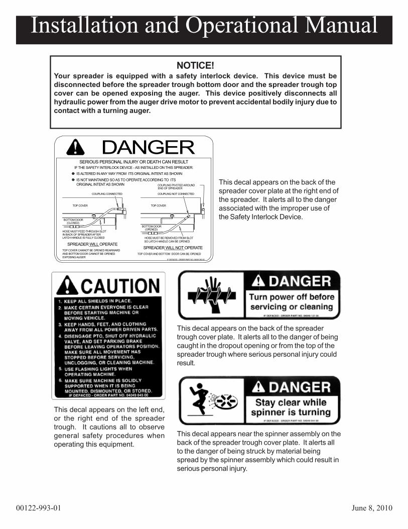
This decal appears on the left end,or the right end of the spreadertrough. It cautions all to observegeneral safety procedures whenoperating this equipment.
NOTICE!Your spreader is equipped with a safety interlock device. This device must bedisconnected before the spreader trough bottom door and the spreader trough topcover can be opened exposing the auger. This device positively disconnects allhydraulic power from the auger drive motor to prevent accidental bodily injury due tocontact with a turning auger.
DANGERSERIOUS PERSONAL INJURY OR DEATH CAN RESULT
IF THE SAFETY INTERLOCK DEVICE - AS INSTALLED ON THIS SPREADER:IS ALTERED IN ANY WAY FROM ITS ORIGINAL INTENT AS SHOWN
IS NOT MAINTAINED SO AS TO OPERATE ACCORDING TO ITS ORIGINAL INTENT AS SHOWN
SPREADER WILL OPERATESPREADER WILL NOT OPERATE
TOP COVER CANNOT BE OPENED REARWARDAND BOTTOM DOOR CANNOT BE OPENED EXPOSING AUGER
TOP COVER AND BOTTOM DOOR CAN BE OPENED
IF DEFACED - ORDER PART NO. 04049 393 00
LATCH HANDLE IS FULLY CLOSEDIN BACK OF SPREADER AFTERHOSE MUST FEED THROUGH SLOT
COUPLING CONNECTED
(CLOSED) BOTTOM DOOR
TOP COVER
HOSE MUST BE REMOVED FROM SLOT SO LATCH HANDLE CAN BE OPENED
(OPENED) BOTTOM DOOR
END OF SPREADER
COUPLING NOT CONNECTED
COUPLING PIVOTED AROUND
TOP COVER
This decal appears on the back of thespreader cover plate at the right end ofthe spreader. It alerts all to the dangerassociated with the improper use ofthe Safety Interlock Device.
This decal appears on the back of the spreadertrough cover plate. It alerts all to the danger of beingcaught in the dropout opening or from the top of thespreader trough where serious personal injury couldresult.
This decal appears near the spinner assembly on theback of the spreader trough cover plate. It alerts allto the danger of being struck by material beingspread by the spinner assembly which could result inserious personal injury.
Installation and Operational Manual
00122-993-01 June 8, 2010
4
Decal Part Number Qty. Description
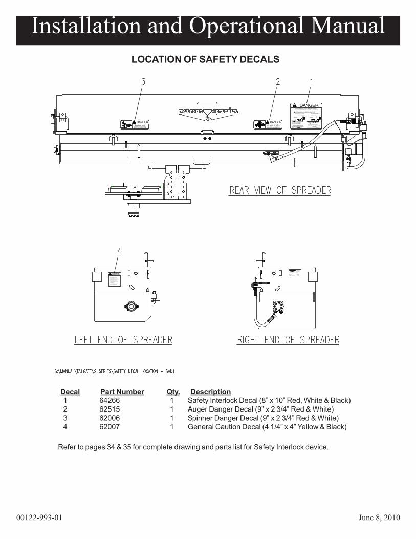
LOCATION OF SAFETY DECALS
OPERATORS POSITION. MAKE SURE ALL MOVEMENT
ALL POWER DRIVEN PARTS.
OR CLEANING MACHINE.
IF DEFACED - ORDER PART NO. 04049 045 00
WHEN IT IS BEING MOUNTED, DISMOUNTED,
5. USE FLASHING LIGHTS WHEN OPERATING MACHINE.
6. MAKE SURE MACHINE IS SOLIDLY SUPPORTED
4. DISENGAGE PTO, SHUT OFF HYDRAULIC VALVE,
HAS STOPPED BEFORE SERVICING, UNCLOGGING,
AND SET PARKING BRAKE BEFORE LEAVING
OR STORED.
CAUTION2. MAKE CERTAIN EVERYONE IS CLEAR BEFORE STARTING MACHINE OR MOVING VEHICLE.
3. KEEP HANDS, FEET, AND CLOTHING AWAY FROM
1. KEEP ALL SHIELDS IN PLACE.
DANGER
IF DEFACED - ORDER PART NO. 04049 044 00
Stay clear whilespinner is turning
DANGER
IF DEFACED - ORDER PART NO. 04049 121 00
Turn power off beforeservicing or cleaning
BOTTOM DOOR
SPREADER WILL NOT OPERATETOP COVER AND BOTTOM DOOR CAN BE OPENED
HOSE MUST FEED THROUGH SLOT
AND BOTTOM DOOR CANNOT BE OPENEDTOP COVER CANNOT BE OPENED REARWARD
SPREADER WILL OPERATE
IN BACK OF SPREADER AFTERLATCH HANDLE IS FULLY CLOSED
EXPOSING AUGERIF DEFACED - ORDER PART NO. 04049 393 00
HOSE MUST BE REMOVED FROM SLOT SO LATCH HANDLE CAN BE OPENED
(OPENED)
IF THE SAFETY INTERLOCK DEVICE - AS INSTALLED ON THIS SPREADER:IS ALTERED IN ANY WAY FROM ITS ORIGINAL INTENT AS SHOWN
DANGERIS NOT MAINTAINED SO AS TO OPERATE ACCORDING TO ITS
SERIOUS PERSONAL INJURY OR DEATH CAN RESULT
ORIGINAL INTENT AS SHOWN
COUPLING CONNECTED
BOTTOM DOOR(CLOSED)
TOP COVER
COUPLING NOT CONNECTED
COUPLING PIVOTED AROUNDEND OF SPREADER
TOP COVER
Description:P, TA, S - -, S3, - - - - - -
Part Number:
May be cove red by one or more of these patents:
3189 355
Serial Number:
0103-1323
Lindenwood, IL 61049127 Walnut Street
(888) 825-7323
00119-651-01
566953135100663332691 3851804
R
0
1 64266 1 Safety Interlock Decal (8” x 10” Red, White & Black)2 62515 1 Auger Danger Decal (9” x 2 3/4” Red & White)3 62006 1 Spinner Danger Decal (9” x 2 3/4” Red & White)4 62007 1 General Caution Decal (4 1/4” x 4” Yellow & Black)
Refer to pages 34 & 35 for complete drawing and parts list for Safety Interlock device.

Installation and Operational Manual
00122-993-01 June 8, 2010
5
CONTROL HYDRAULICS SPECIFICATIONSAND INSTALLATION
CONTROL AND HYDRAULIC SYSTEM SPECIFICATIONS:
• Hydraulic Oil ------------------------------------------- Good Grade of MS10W Hydraulic Oil which has wear, oxidation and foam inhibitors.
• Oil Filter ------------------------------------------------- 10 Micron Element In Return Line
• Relief Valve Setting ------------------------------------------------------------------ 1500 PSI
• Oil Flow ------------------------------------------------------- Conveyor (A-Port) 0-15 GPM Spinner (S-Port) 0-7 GPM

Installation and Operational Manual
00122-993-01 June 8, 2010
6
CO
NTR
OL
HYD
RA
ULI
CS
INST
ALL
ATIO
N
T
S
PA
HYD
RAU
LIC
INTE
RLO
CK

Installation and Operational Manual
00122-993-01 June 8, 2010
7
CONTROL HYDRAULICS INSTALLATION (Continued)
system.
2. Standard pump, valve, tank and hose kits make up the complete system.
3. This diagram may be used to install an entire system, or part of a system, dependingupon kits supplied, and existing components on truck.
4. Alternate proven methods and components are acceptable to suit various truck modelrequirements.
5. Hydraulic components should be kept as clean as possible during assemblyoperations.
6. Galvanized pipe and pipe fittings should not be used because flaking of galvanizing material can cause damage to major hydraulic components.
7. A pipe joint sealant, compatible with hydraulic oil, must be applied to all screwedfittings. (Teflon tape is not recommeneded.)
8. Sufficient hose should be allowed for raising dump body without kinking or stretchinghose.
9. Hose should be protected where severe wear may be caused by vibration or slidingmovement.
10. Long runs of hose should be supported by nylon ties or clamping.
11. Auger and Spinner pressure and return hoses may be reversed for proper motorrotation.
12. Three hose lines to rear of truck may be installed inside truck frame, under dump bodyfloor, and secured in place.
13. Use hose manufacturers recommendations for fitting reusable hose ends.
1. This diagram is Meyer Products complete recommended hydraulic
Installation and Operational Manual
00122-993-01 June 8, 2010
8
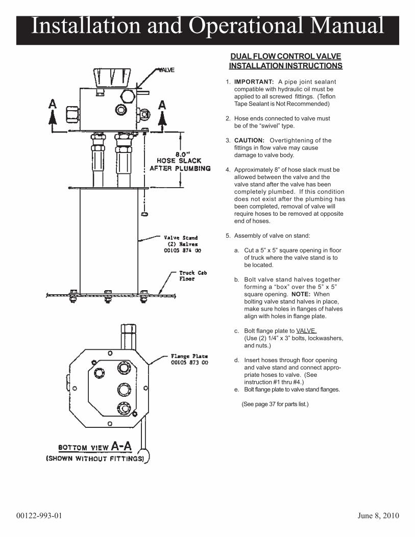
DUAL FLOW CONTROL VALVEINSTALLATION INSTRUCTIONS
1. IMPORTANT: A pipe joint sealantcompatible with hydraulic oil must beapplied to all screwed fittings. (TeflonTape Sealant is Not Recommended)
2. Hose ends connected to valve mustbe of the “swivel” type.
3. CAUTION: Overtightening of thefittings in flow valve may causedamage to valve body.
4. Approximately 8” of hose slack must beallowed between the valve and thevalve stand after the valve has beencompletely plumbed. If this conditiondoes not exist after the plumbing hasbeen completed, removal of valve willrequire hoses to be removed at oppositeend of hoses.
5. Assembly of valve on stand:
a. Cut a 5” x 5” square opening in floorof truck where the valve stand is tobe located.
b. Bolt valve stand halves togetherforming a “box” over the 5” x 5”square opening. NOTE: Whenbolting valve stand halves in place,make sure holes in flanges of halvesalign with holes in flange plate.
c. Bolt flange plate to VALVE.(Use (2) 1/4” x 3” bolts, lockwashers,and nuts.)
d. Insert hoses through floor openingand valve stand and connect appro-priate hoses to valve. (Seeinstruction #1 thru #4.)
e. Bolt flange plate to valve stand flanges.
(See page 37 for parts list.)
VALVE
Installation and Operational Manual
00122-993-01 June 8, 2010
9
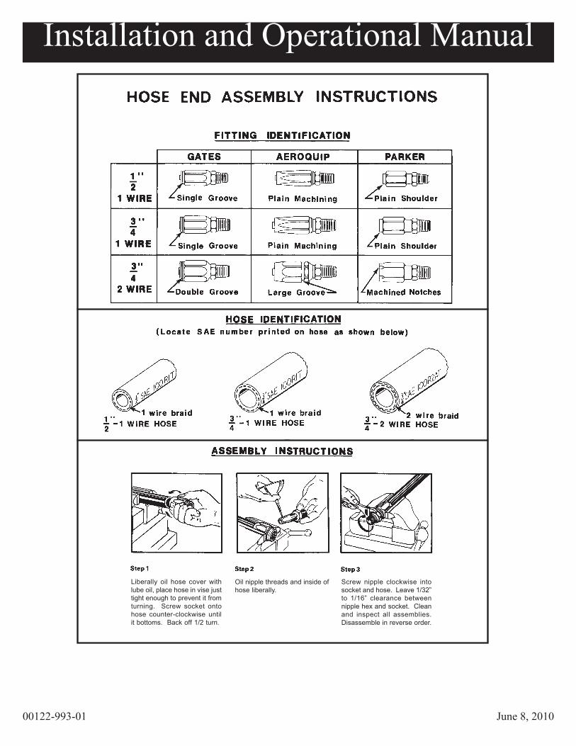
Liberally oil hose cover withlube oil, place hose in vise justtight enough to prevent it fromturning. Screw socket ontohose counter-clockwise untilit bottoms. Back off 1/2 turn.
Oil nipple threads and inside ofhose liberally.
Screw nipple clockwise intosocket and hose. Leave 1/32”to 1/16” clearance betweennipple hex and socket. Cleanand inspect all assemblies.Disassemble in reverse order.
Installation and Operational Manual
00122-993-01 June 8, 2010
10
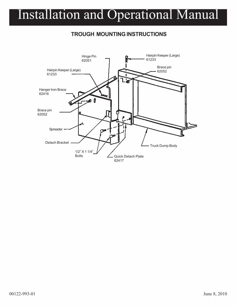
TROUGH MOUNTING INSTRUCTIONS
Hinge Pin
Hairpin Keeper (Large)
Hanger Iron Brace
Brace pin
Spreader
Detach Bracket
1/2” X 1 1/4”Bolts Quick Detach Plate
Truck Dump Body
Brace pin
Hairpin Keeper (Large)6123362051
61233
62416
62052
62052
62417

Installation and Operational Manual
00122-993-01 June 8, 2010
11
TROUGH MOUNTING INSTRUCTIONS(Continued)
GENERAL:This spreader is designed to mount rigidly on the rear of the truck dump body, below the tail-gate, and supported by brackets bolted to the rub rails of the dump body. Instructional drawingis included in this manual to show the details on page 10.
Support spreader and other heavy components solidly when positioning for mounting on truckdump body.
IMPORTANT:On occasion, due to improper handling during shipment or storage, the vertical ends of thetrough get bent in or out slightly. Be sure these are square and true before installation. Onceinstalled, the mounting brackets should prevent further deformation.
1. Position the spreader under the dump body tailgate with the auger drive housing tothe right side of the truck. The trough lip on the forward side of the spreader shouldbe as close as possible to the cross member under the floor of the dump body.
The tailgate of the dump body should lay down horizontally over the spreader, yet thespreader must be mounted up under the tailgate as high as possible.
2. Pin quick detach plates to spreader detach brackets.
3. Position quick detach plates against dump body cornerposts and clamp in a levelposition. Weld adequately to support loaded spreader trough. If bolting, is desired,drill (2) holes for 1/2” bolts simultaneously through bracket and cornerpost and boltsolidly.
4. Position hanger iron brace on brace pin located on spreader endplates.
5. Locate brace pins on dump body cornerposts approximately as shown using bracesfor exact positioning. (Braces may require bending for proper fit.)
6. Weld brace pins solidly to dump body, and retain braces at each end with hairpinkeepers.
7. Carefully remove temporary spreader positioning apparatus..
8. If there is a gap between the trough lip and the dump body rear cross member, a“spillboard” of about 3/16” x 2” steel may be welded or bolted to the forward lip of thespreader to form a seal under the dump body floor. It may have to be notched or cutto fit around tailgate latches or other obstructions on the rear of the dump body.
tailgate to prevent material spillage over the ends of the spreader.
DANGER
9. Tailgate shields (62412), if required, are bolted or welded to the inside of the

Installation and Operational Manual
00122-993-01 June 8, 2010
12
INSTALLATION OF SPINNER ASSEMBLIES ON“S” SERIES SPREADERS
(See pages 14-19.)
SUPPORT SPINNER ASSEMBLY SOLIDLY WHENMOUNTING ON SPREADER.
SPINNER ASSEMBLY PROCEDURE:
1. Attach spinner shield to spinner frame with 5/16” x 3/4” bolts and nuts.
2. Attach spinner disc to hub with 5/16” x 1 1/2” bolts, flatwashers and flange nuts.
3. Apply anti-seize compound to spinner motor shaft.
4. Mount spinner disc/hub assembly on spinner motor shaft.
5. Secure disc/hub assembly to motor shaft with proper size hardware (provided). Bolt shouldengage threads in motor shaft a minimum of 3/8” when bolt is tight.
6. Attach spinner frame assembly to spinner extension mounting bracket with (4) 3/8” X 1”bolts and flange nuts.
a. Appropriate spinner height depends on truck frame ground clearance. A shorterspinner height for light and medium duty trucks with contractor style bodies, ataller spinner height for heavy duty trucks with full size dump bodies.
7. While holding lock collar in middle notch of spinner extension mounting bracket, slidespinner hinge rod through both the mounting bracket and lock collar.
(TMS)TROUGH MOUNTED SPINNER OPTION:
1. See pages 16 through 19 for additional instructions.
MOUNTING PROCEDURES:
TRUCK SHOULD BE ON LEVEL SURFACE.
1. Install spinner assembly on spreader by sliding the hinge rod into the mounting tabs onbottom door. Insert (2) keeper pins into hinge rod. Center and lock spinner assemblybetween mounting tabs.
2. Raise and lower dump body to check spinner ground clearances. Adjustspinner height if needed. Repeat step if adjustments are made.
DANGER

Installation and Operational Manual
00122-993-01 June 8, 201013
INSTALLATION OF SPINNER ASSEMBLIES ON“S” SERIES SPREADERS
(Continued)
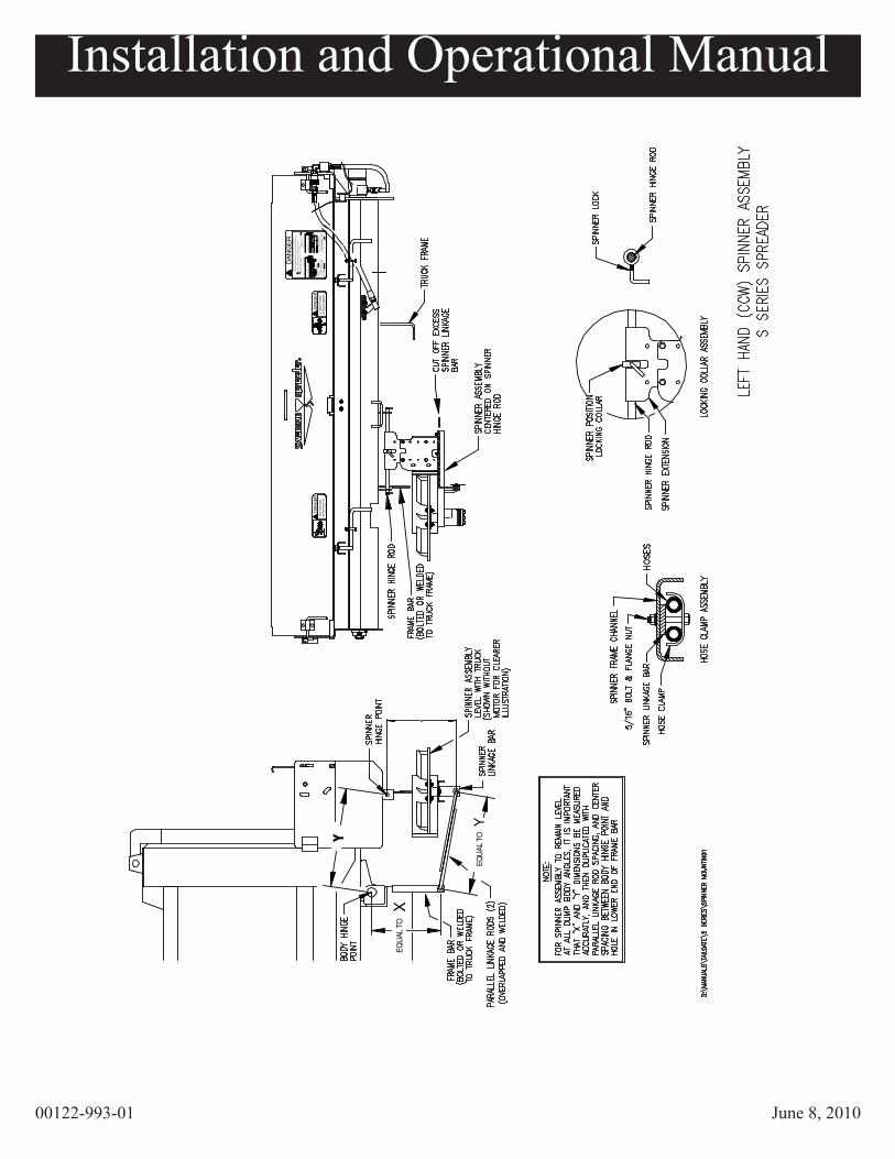
3. Position spinner linkage bar under spinner frame channel so that L-Bend aligns with truckframe. Secure linkage bar to spinner frame with 5/16” X 1” bolt and flange nut, using theinside mounting hole. (Outside mounting hole is for hydraulic hose clamp.) Cut off anyexcess linkage bar if required.
4. With spinner disc level with ground, measure and record the distance betweencenterline of spinner hinge rod(s) and centerline of hole in spinner linkage bar(s)for dimension “X”. Measure and record the space between centerline of dump body hingepins and centerline of spinner hinge rod(s) for dimension “Y”.
DIMENSION “X” ___________________
DIMENSION “Y” ___________________
5. Temporarily clamp frame bar(s) in position (hole pointing down) against truck frame.Locate mounting hole below dump body hinge pins using “X” and “Y” dimensions fromstep 5.
6. Attach parallel linkage rods to the frame bars and in the spinner linkage bar(s)with 1/2” flatwasher and keeper pins. Overlap and temporarily clamp rods together.
7. Raise and lower dump body while checking spinner for binding and leveloperation at all dump angles. Check that temporary connection bars are not moving.
8. Secure frame bar(s) to truck frame in compliance with truck manufactures recommenda-tions. Weld parallel linkage rod together. Remove all temporary clamps.
9. Attach spinner hydraulic hoses to spinner motor (use pipe thread sealant if applicable).Secure hoses to spinner frame with clamp and hardware provided.
Installation and Operational Manual
00122-993-01 June 8, 2010
14
X
EQUA
L TO
Y
EQUA
L TO
X
spinn
er is
turn
ing
Stay
clea
r whi
leDA
NGER
IF D
EFAC
ED -
ORD
ER P
ART
NO. 0
4049
044
00
servi
cing o
r clea
ning
Turn
powe
r off b
efore
DANG
ER
IF D
EFAC
ED -
ORDE
R PA
RT
NO. 0
4049
121
00
END
OF S
PREA
DER
COUP
LIN
G PI
VOTE
D A
ROUN
D
COUP
LIN
G N
OT C
ONN
ECTE
D
SERI
OUS
PER
SONA
L IN
JURY
OR
DEA
TH C
AN R
ESUL
T
IS N
OT
MAI
NTAI
NED
SO
AS
TO O
PERA
TE A
CCO
RDIN
G TO
ITS
DA
NG
ER
IS A
LTER
ED IN
ANY
WAY
FRO
M I
TS O
RIG
INAL
INTE
NT
AS S
HOW
N
IF T
HE
SAFE
TY IN
TERL
OCK
DEV
ICE
- AS
INST
ALLE
D O
N TH
IS S
PREA
DER
:
SO
LAT
CH H
AND
LE C
AN
BE O
PENE
DHO
SE M
UST
BE
REM
OVE
D FR
OM
SLO
T
IF D
EFA
CED
- ORD
ER
PART
NO.
040
49 3
93 0
0
TOP
COV
ER A
ND B
OTT
OM
DO
OR
CAN
BE
OP
ENE
D
SPRE
ADER
WIL
L NOT
OPE
RATE
BOTT
OM
DO
OR
SPRE
ADER
WIL
L OP
ERAT
ETO
P CO
VER
CAN
NOT
BE
OPE
NED
RE
ARW
ARD
AND
BOTT
OM D
OOR
CAN
NOT
BE
OPE
NED
EXPO
SIN
G AU
GER
LATC
H HA
NDL
E IS
FUL
LY C
LOS
EDIN
BAC
K O
F SP
REA
DER
AFT
ERHO
SE M
UST
FEED
THR
OUG
H S
LOT
(CLO
SED
) BO
TTO
M D
OO
R(O
PEN
ED)
COUP
LING
CON
NECT
ED
OR
IGIN
AL IN
TEN
T AS
SH
OWN
TOP
COV
ERTO
P CO
VER
Y

Installation and Operational Manual
00122-993-01 June 8, 2010
20
OPERATING INSTRUCTIONS
1. WHEN STARTING UP NEW EQUIPMENT, BE SURE EVERYONE IS STANDING CLEAR, WATCHFOR ANYTHING THAT MAY REQUIRE SHUTTING SYSTEM DOWN. EQUIPMENT MUST BESTARTED UP SLOWLY AND WATCHED FROM A SAFE DISTANCE. WATCH FOR ANYTHING THATMAY BE HITTING SOMETHING THAT IT SHOULD NOT BE HITTING, AND LISTEN FOR SOUNDSTHAT ARE ABNORMAL. CORRECT ANYTHING THAT IS ABNORMAL BEFORE CONTINUING USEOF THE EQUIPMENT.
2. BEFORE INSTALLATION, MAINTENANCE, CLEANING, OR REMOVAL OF SPREADER, ALLHYDRAULIC VALVES, PTO, AND TRUCK ENGINE MUST BE SHUT OFF.
3. WHEN SPREADER IS REMOVED FROM VEHICLE, OR NOT IN USE, THE VALVE ON-OFF LEVERSHOULD BE IN THE “OFF” POSITION. IF LEFT IN “ON” POSITION EXCESSIVE HEAT MAY OCCURIF PUMP CONTINUES TO PUMP OIL THROUGH THE HYDRAULIC VALVE. THIS THEN COULDCAUSE A HOSE TO BURST SPRAYING HOT OIL ON THOSE NEARBY.
INITIAL START UP:This spreader is equipped with a hydraulic safety interlock device designed to interrupt oil flow to the augermotor when disconnected. The spreader is shipped with the interlock device in the disconnected position andmust be connected for operating the spreader.
1. Connect hydraulic hoses to safety interlock, spreader and spinner.
2. Fill reservoir about three-fourths full with hydraulic oil. (See page 5 for type.)KEEP OIL CLEAN.
3. Start truck engine.
4. Be sure valve ON-OFF lever is in “OFF” position.
5. Keep auger and spinner knobs on valve in closed position.
6. Engage PTO and allow hydraulic oil to circulate several minutes to warm up.
7. Open both valve knobs to first position.
8. Move valve ON-OFF lever to “ON” position.
9. Examine auger and spinner to see if they are functioning properly. (They will be operating slowly.)(Left hand mounted spinner should turn in CCW rotation, and right hand mounted spinner shouldturn in CW rotation, as viewed from above spinner. Auger should turn in direction which makesauger fliting appear to move towards trough dropout opening.)
10. Open valve knobs to other positions and check to see if spinner and auger operate faster as knobs areopened, and slower as knobs are closed.
11. Turn valve knobs to closed position and move ON-OFF lever to “OFF” position.
12. Shut truck engine off.
13. Check entire hydraulic system for leaks.
14. Refill reservoir to three-fourths full.
15. Hydraulic system is now ready for use.
DANGER
Installation and Operational Manual
00122-993-01 June 8, 2010
21
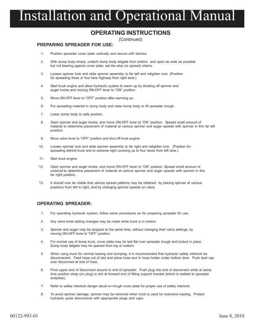
OPERATING SPREADER:
1. For operating hydraulic system, follow same procedures as for preparing spreader for use.
2. Any valve knob setting changes may be made while truck is in motion.
3. Spinner and auger may be stopped at the same time, without changing their valve settings, bymoving ON-OFF lever to “OFF” position.
4. For normal use of dump truck, cover plate may be laid flat over spreader trough and locked in place.Dump body tailgate may be opened from top or bottom.
5. When using truck for normal hauling and dumping, it is recommended that hydraulic safety interlock bedisconnected. Feed hose out of slot and place hose end in hose holder under bottom door. Push dust capover disconnect at end of hose.
6. Pivot upper end of disconnect around to end of spreader. Push plug into end of disconnect while at sametime position strap (on plug) in slot at forward end of fitting support bracket (which is welded to spreaderendplate).
7. Refer to safety interlock danger decal on trough cover plate for proper use of safety interlock.
8. To avoid spinner damage, spinner may be removed when truck is used for extensive hauling. Protecthydraulic quick disconnects with appropriate plugs and caps.
OPERATING INSTRUCTIONS(Continued)
PREPARING SPREADER FOR USE:
1. Position spreader cover plate vertically and secure with latches.
2. With dump body empty, unlatch dump body tailgate from bottom and open as wide as possiblebut not bearing against cover plate, set the stop (or spread) chains.
3. Loosen spinner lock and slide spinner assembly to far left and retighten lock. (Positionfor spreading three or four lane highway from right lane.)
4. Start truck engine and allow hydraulic system to warm up by shutting off spinner andauger knobs and moving ON-OFF lever to “ON” position.
5. Move ON-OFF lever to “OFF” position after warming up.
6. Put spreading material in dump body and raise dump body to fill spreader trough.
7. Lower dump body to safe position.
8. Open spinner and auger knobs, and move ON-OFF lever to “ON” position. Spread small amount ofmaterial to determine placement of material at various spinner and auger speeds with spinner in this far leftposition.
9. Move valve lever to “OFF” position and shut off truck engine.
10. Loosen spinner lock and slide spinner assembly to far right and retighten lock. (Position forspreading behind truck and to extreme right covering up to four lanes from left lane.)
11. Start truck engine.
12. Open spinner and auger knobs, and move ON-OFF lever to “ON” position. Spread small amount ofmaterial to determine placement of material at various spinner and auger speeds with spinner in thisfar right position.
13. It should now be visible that various spread patterns may be obtained by placing spinner at variouspositions from left to right, and by changing spinner speeds on valve.

Installation and Operational Manual
00122-993-01 June 8, 2010
Installation and Operational Manual
00122-993-01 June 8, 201022
Serious personal injury can result from beingcaught in a turning spinner. Stay clear and keepall others clear when spinner is turning.
Serious personal injury can result if hit by flyingparticles being thrown by a turning spinner.
Stand back, and keep all others back at least 50feet while spinner is turning. DO NOT ASSUMEthat particles cannot be thrown by a turningspinner just because material is not beingdropped onto the spinner; particles that have beensticking to the spinner may suddenly come looseand be thrown causing possible injury.
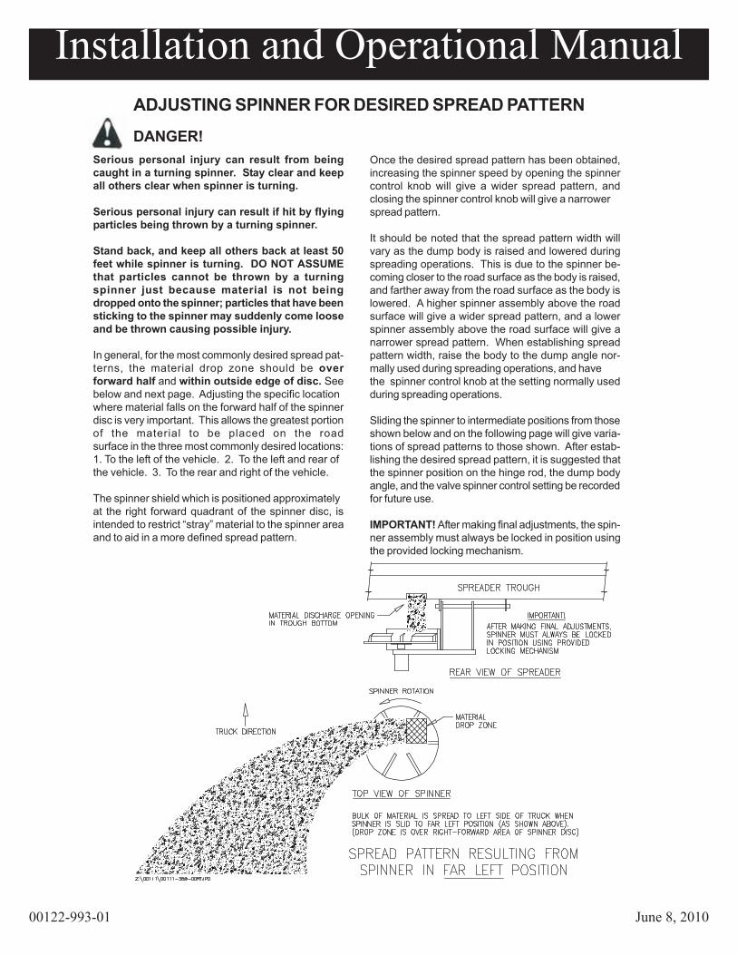
In general, for the most commonly desired spread pat-terns, the material drop zone should be overforward half and within outside edge of disc. Seebelow and next page. Adjusting the specific locationwhere material falls on the forward half of the spinnerdisc is very important. This allows the greatest portionof the material to be placed on the roadsurface in the three most commonly desired locations:1. To the left of the vehicle. 2. To the left and rear ofthe vehicle. 3. To the rear and right of the vehicle.
The spinner shield which is positioned approximatelyat the right forward quadrant of the spinner disc, isintended to restrict “stray” material to the spinner areaand to aid in a more defined spread pattern.
ADJUSTING SPINNER FOR DESIRED SPREAD PATTERN
DANGER!Once the desired spread pattern has been obtained,increasing the spinner speed by opening the spinnercontrol knob will give a wider spread pattern, andclosing the spinner control knob will give a narrowerspread pattern.
It should be noted that the spread pattern width willvary as the dump body is raised and lowered duringspreading operations. This is due to the spinner be-coming closer to the road surface as the body is raised,and farther away from the road surface as the body islowered. A higher spinner assembly above the roadsurface will give a wider spread pattern, and a lowerspinner assembly above the road surface will give anarrower spread pattern. When establishing spreadpattern width, raise the body to the dump angle nor-mally used during spreading operations, and havethe spinner control knob at the setting normally usedduring spreading operations.
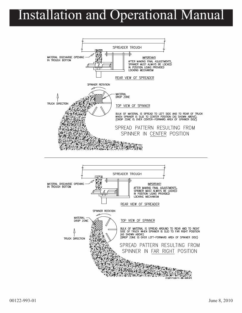
Sliding the spinner to intermediate positions from thoseshown below and on the following page will give varia-tions of spread patterns to those shown. After estab-lishing the desired spread pattern, it is suggested thatthe spinner position on the hinge rod, the dump bodyangle, and the valve spinner control setting be recordedfor future use.
IMPORTANT! After making final adjustments, the spin-ner assembly must always be locked in position usingthe provided locking mechanism.
Installation and Operational Manual
00122-993-01 June 8, 2010
23

Installation and Operational Manual
00122-993-01 June 8, 2010
24
RECOMMENDED REGULAR MAINTENANCE
SERIOUS PERSONAL INJURY CAN RESULT FROM BEING CAUGHT IN A TURNING AUGER, A TURNINGSPINNER, OR OTHER OPERATING TRUCK EQUIPMENT. BEFORE PERFORMING MAINTENANCEOPERATIONS, PARK VEHICLE ON LEVEL GROUND. SET PARKING BRAKE, SHUT OFF ALL POWER,AND SHUT OFF TRUCK ENGINE. ALWAYS REPLACE SHIELDS AND COVERS WHEN MAINTENANCE ISCOMPLETE.
1. Maintain a three-fourths full reservoir using high grade non-foaming hydraulic oil.(See page 5.)
2. Avoid getting contaminants in reservoir when filling.
3. Replace filter cartridge with new cartridge at least twice a year and more often ifnecessary. (If installed, filter condition gauge has red zone indicating whencartridge needs changing.)
4. Clean hydraulic quick disconnects before taking apart or connecting.
5. Protect hydraulic quick disconnects while in use and after taking apart with oilyrag or other suitable protection.
6. Auger bearing requires periodic greasing every 15 hours of use and more frequent greasing during periods of greater use.
7. Greasing spinner hinge rod at support pivot points is suggested.
8. Hosing down and cleaning spreader after each use, and repainting or oiling aftereach season will greatly prolong spreader life. To open bottom door and top cover,disconnect hydraulic safety interlock and pivot around to end of spreader.
9. Spreader trough should be completely emptied after each use during severe coldweather to prevent material from freezing around auger.
DANGER

Installation and Operational Manual
00122-993-01 June 8, 2010
25
valves or electric components.
CONDITION 2Slow operation of auger and/or spinner.
CAUSEa. Worn or defective pump.b. Worn or defective motor.c. Pump cavitation.d. Insufficient pump speed.
CORRECTION a. Repair of replace pump. b. Repair or replace motor. c. Refer to pump section. d. Pump capacity is 16 GPM at 1000 RPM.
Increase PTO accordingly.
CONDITION 3Erratic operation of auger and/or spinner.
CAUSEa. Low Oil.b. Worn or defective motor.c. Dirty, worn or defective flow control valve.d. Plugged filter.e. Relief valve setting too low.f. Pump cavitation.g. Air vent on reservoir tank is blocked.
CORRECTION a. Fill reservoir to a 3/4 full level. b. Repair or replace motor. c. Clean repair or replace flow control. d. Replace filter element and clean filter base. e. Adjust relief valve for 1500 PSI. f. Refer to condition 1. g. Clean or replace vent cap to admit
atmospheric pressure to inside of tank.
CONDITION 1Pump cavitation recognized by excessive noise.
CAUSEa. Air entering system through suction lines.b. Suction line kinked, twisted or too long.c. Inadequate size suction line.d. Hydraulic oil too heavy.e. Excessive pump speed. Normal pump speed
should be 1200 to 1500 RPM.
CORRECTIONa. Check line from reservoir for possible leaks.b. Install suction line as short and straight as
possible.c. Increase suction line size.d. Drain and replace with a lower viscosity
hydraulic oil.e. Pump capacity is 16 GPM at 1000 RPM.
Decrease PTO speed accordingly.
HYDRAULIC TROUBLE-SHOOTING CHART
CONDITION 4Auger and/or spinner will not operate, oroperates in wrong direction.
CAUSEa. Quick disconnects are dirty or damaged
causing incomplete connection.b. System hose connections wrong.c. Hose connections wrong, causing motors to
operate in wrong direction.d. Foreign material in valve compensator section.
CORRECTIONa. Clean or replace and properly connect.b. Refer to plumbing diagram for proper hose
connections, and reconnect.c. Refer to illustration for proper hose connections
at motor and reconnect.d. Remove compensator section and clean.
NOTE: If a motor operates in the wrong direction,reverse hose connections at motor ports(usually easier).
NOTE: Meyer Products Inc. warranty does not cover unauthorized disassembly of hydraulic pumps, motors,

Installation and Operational Manual
00122-993-01 June 8, 2010
UTGS SPREADER PARTS LISTING
AND PARTS DIAGRAMS
Installation and Operational Manual
00122-993-01 June 8, 2010
IF D
EFA
CED
- OR
DER
PART
NO
. 040
49 1
21 0
0
DA
NG
ERSt
ay c
lear
whi
lesp
inne
r is
turn
ing
IF D
EFA
CED
- OR
DER
PART
NO
. 040
49 0
44 0
0
DA
NG
ERTO
P C
OV
ER
AN
D B
OTT
OM
DO
OR
CA
N B
E O
PEN
ED
SPR
EAD
ER W
ILL
NO
T O
PER
ATE
HO
SE
MU
ST B
E R
EM
OVE
D F
RO
M S
LOT
CO
UP
LIN
G N
OT
CO
NN
ECTE
D
CO
UP
LIN
G P
IVO
TED
AR
OU
ND
IS A
LTE
RE
D IN
AN
Y W
AY
FR
OM
ITS
OR
IGIN
AL
INTE
NT
AS
SHO
WN
IF T
HE
SAFE
TY IN
TER
LOC
K D
EVIC
E - A
S IN
STA
LLED
ON
TH
IS S
PREA
DER
:
IF D
EFA
CED
- OR
DER
PART
NO
. 040
49 3
93 0
0
HO
SE
MU
ST F
EED
TH
RO
UG
H S
LOT
AN
D B
OTT
OM
DO
OR
CA
NN
OT
BE
OPE
NED
TO
P C
OV
ER
CA
NN
OT
BE
OPE
NED
REA
RW
AR
D
SPR
EAD
ER W
ILL
OPE
RA
TE
IN B
AC
K O
F SP
RE
AD
ER A
FTER
LATC
H H
AN
DLE
IS F
ULL
Y C
LOSE
D
EX
PO
SIN
G A
UG
ER
SO
LA
TCH
HA
ND
LE C
AN
BE
OPE
NED
OR
IGIN
AL
INTE
NT
AS
SHO
WN
IS N
OT
MA
INTA
INED
SO
AS
TO
OP
ERA
TE A
CC
OR
DIN
G T
O I
TS
SER
IOU
S PE
RSO
NA
L IN
JUR
Y O
R D
EATH
CA
N R
ESU
LT
BO
TTO
M D
OO
R(C
LOS
ED)
TOP
CO
VER
BO
TTO
M D
OO
R
CO
UP
LIN
G C
ON
NEC
TED
(OP
ENED
)
TOP
CO
VER
EN
D O
F SP
RE
AD
ER
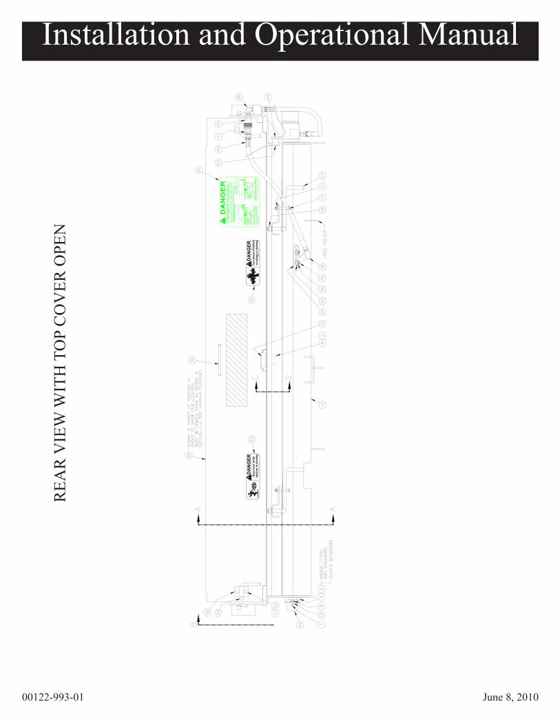
REA
R V
IEW
WIT
H T
OP
CO
VER
OPE
N

Installation and Operational Manual
00122-993-01 June 8, 2010
TOP
VIE
W W
ITH
TO
P C
OV
ER O
PEN
Installation and Operational Manual
00122-993-01 June 8, 2010
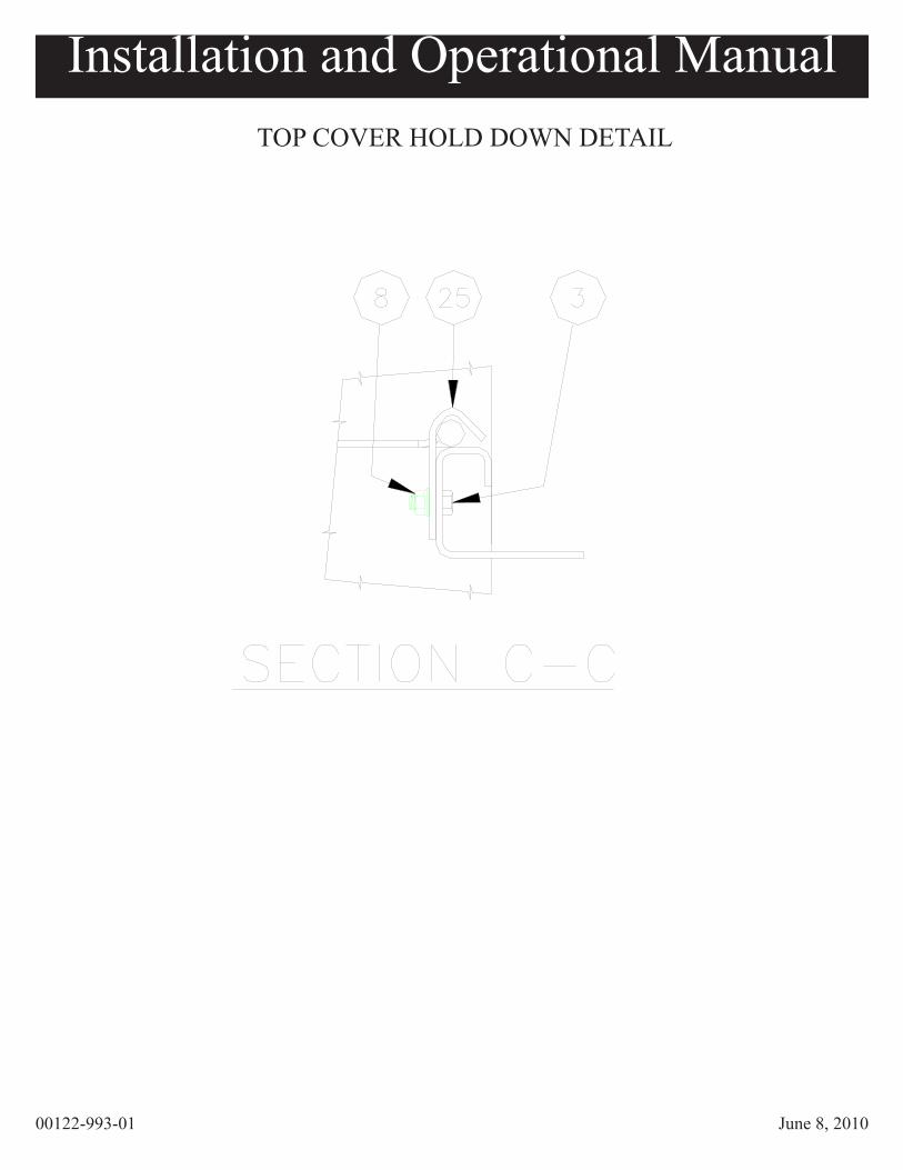
TOP COVER HOLD DOWN DETAIL
Installation and Operational Manual
00122-993-01 June 8, 2010
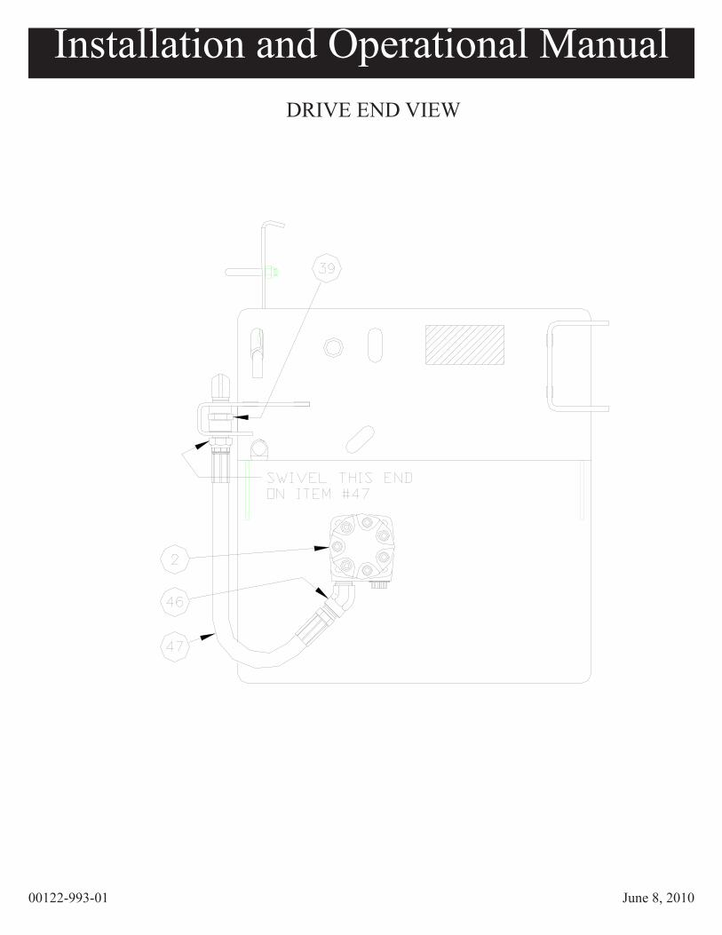
DRIVE END VIEW

Installation and Operational Manual
00122-993-01 June 8, 2010
BEARING END VIEWCROSS-SECTION
Installation and Operational Manual
00122-993-01 June 8, 2010
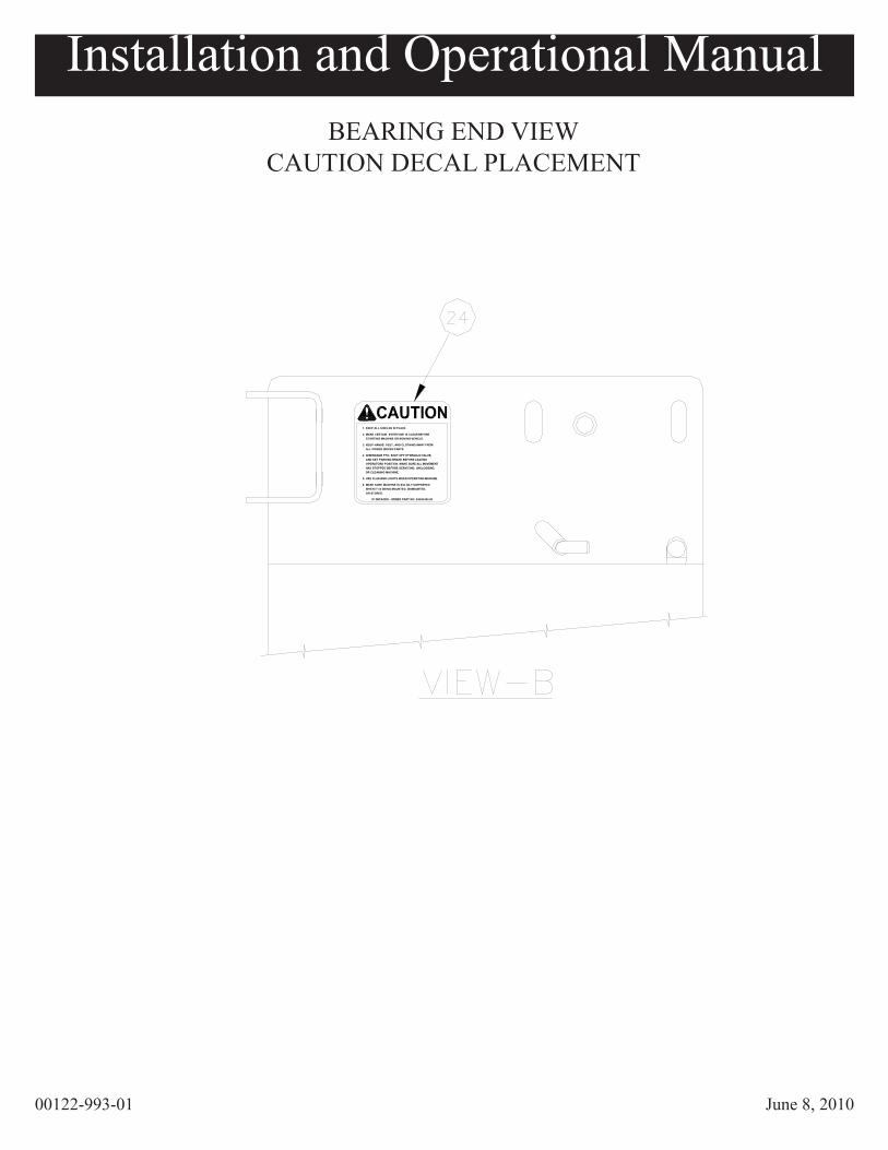
5. USE FLASHING LIGHTS WHEN OPERATING MACHINE.
6. MAKE SURE MACHINE IS SOLIDLY SUPPORTED
IF DEFACED - ORDER PART NO. 04049 045 00
WHEN IT IS BEING MOUNTED, DISMOUNTED, OR STORED.
ALL POWER DRIVEN PARTS.
4. DISENGAGE PTO, SHUT OFF HYDRAULIC VALVE,
OR CLEANING MACHINE.
OPERATORS POSITION. MAKE SURE ALL MOVEMENT HAS STOPPED BEFORE SERVICING, UNCLOGGING,
AND SET PARKING BRAKE BEFORE LEAVING
2. MAKE CERTAIN EVERYONE IS CLEAR BEFORE STARTING MACHINE OR MOVING VEHICLE.
3. KEEP HANDS, FEET, AND CLOTHING AWAY FROM
1. KEEP ALL SHIELDS IN PLACE.
BEARING END VIEWCAUTION DECAL PLACEMENT

Installation and Operational Manual
00122-994-01 July 22, 2010
User Component Description Qty per
2 64283 Motor, Hyd White 23.7 Cid 1
3 63205 Bolt, 3/8-16 X 3/4 Hh Ss 6
4 63206 Lockwasher, 3/8” Med Split Ss 4
5 62480 Washer, Felt 1 1/4id X2 1/2od 1
6 61163 Bearing, 1 1/4” 1
7 64070 Bolt, 3/8-16 X 1-3/4 Hh Ss 2
8 62473 Nut, 3/8-16 Ser Flange Ss 4
9 63681 Coupling, Drive Cs 1
10 64236 Weld, Bot Door 10g S2 Utgs Mey 1
11 62695 Bolt, 3/8-16 X 1-1/4 Hh Ss 3
12 63384 Locknut, 3/8-16 Nl Ss 9
13 63198 Bolt, 3/8-16 X 2-1/2 Hh Ss 2
14 63680 Insert, Auger 1
15 63277 Bolt, 1/2-13 X 3-1/2 Hh G8 Zp 1
16 63276 Locknut, 1/2-13 Top Lock Zp 1
17 63276 Weld, Sad/Sag Auger 1
18 64237 Cover, Anti-Flow 10g S2 1
19 63461 Keeper, Hairpin Large, Ss 2
20 64235 Weld, Top Covr 10g S2 Utgs Mey 1
22 62515 Decal, Danger (Auger) 1
23 62006 Decal, Danger (Spinner) 1
24 62007 Decal, Caution 1
25 64052 Clip, Hold-Down 10g S2 1
26 22230 Flatwasher, 3/8” U.S.S. Ss 2
27 64004 Latch, Bottom Door S3 2
28 63425 Locknut, 5/8-11 Top Lock Ss 2
29 64054 Handle, Lift S3 1
30 64384 Bracket, S2 2
1 64383 Weld, Trough Utgs S2 Magnum 1
Y, trough Utgs S2 Parts List

Installation and Operational Manual
00122-993-01 June 8, 2010
User Component Description Qty per
31 63283 Bolt, 5/16-18 X 5/8 Ca Ss 4
32 63310 Nut, 5/16-18 Ser Flange Ss 4
33 62731 Handle, Ss 2
34 62585 Weld, Coupling Plate Cs 1
35 63468 Bolt, 3/8-16 X 1 Ca Ss Sht Nk 2
36 63199 Locknut, 3/8-16 Top Lock Ss 2
37 64266 Decal, Safety Interlock 1
38 63469 Plug, 1/2” Npt (Ca9) 1
39 64263 Coupling, 1/2” Ind. Pipe 1
40 64264 Elbow, 1/2” X 90 Deg Solid 1
41 62592 Quick Disconnect, 1/2” Male 1
42 62591 Quick Disconnect, 1/2” Female 1
43 62594 Dust Cap, 1/2” 1
44 62593 Dust Plug, 1/2” 1
45 64265 Hose, 1/2” X 28” (1) Wire 1
46 64261 Elbow, 1/2” X 45 Deg 1
47 64262 Hose, 1/2” X 19” 1
48 63128 Trim, Vinyl 0.8 ft
49 64385 Cover, Bearing Shaft Hdpe 1
Y,Trough Utgs S2 Parts List (cont’d)
Installation and Operational Manual
00122-993-01 June 8, 2010
1
2
3
5
4
6
7
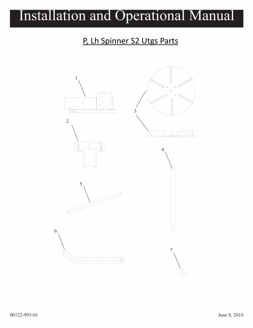
P, Lh Spinner S2 Utgs Parts

User Component Description Qty per
1 00122-983-03weld, spnr frame Utgs S2
1
NS04101-035-00
Motor, hydraulic (3 cid)1
2 00122-987-03Plate, Ext. 10g S2 Utgs
1
3 04622-002-00Disc, Poly spinner 18” ccw
1
4 00122-982-03Iron, Hanger 10g S2 Utgs
2
5 00109-374-00Rod Hinge, S3
1
NS06012-003-00
Machining, Spinner Hub1
6 06070-003-01Pin, Hinge, S3
2
NS00122-977-02
Detach, Truck2
7 06070-003-01Pin, Brace, S3
2
NS04011-001-04
Keeper, Hairpin, large ss4
NS62,769
Collar, set 1”1
P, Lh Spinner S2 Utgs Parts Listing
Installation and Operational Manual
NS = Not Shown
Installation and Operational Manual
00122-993-01 June 8, 2010
34
CALL YOUR AUTHORIZED MEYER PRODUCTS DEALER FOR PARTS AND SERVICEMEYER PRODUCTS (216) 486-1313
FAX (216) 486-9775email: [email protected]
NOTICE: INSTRUCTIONAL MATERIAL AND PARTS LISTS INCLUDED IN THIS MANUAL ARE SUBJECT TO CHANGE WITHOUT NOTICE.
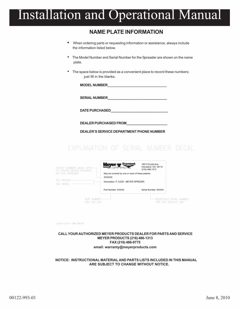
NAME PLATE INFORMATION
• When ordering parts or requesting information or assistance, always include the information listed below.
• The Model Number and Serial Number for the Spreader are shown on the name plate.
• The space below is provided as a convenient place to record these numbers; just fill in the blanks.
MODEL NUMBER________________________________
SERIAL NUMBER________________________________
DATE PURCHASED_______________________________
DEALER PURCHASED FROM______________________
DEALER’S SERVICE DEPARTMENT PHONE NUMBER
18513 Euclid Ave.Cleveland, OH 44112(216) 486-1313
Part Number: XXXXX
Description: P, SJDS - MEYER SPREDER
XXXXXX
May be covered by one or more of these patents:
Serial Number: XXXXX
Installation and Operational Manual
00122-993-01 June 8, 2010
35
SPREADER ONE YEAR WARRANTY Meyer Products (“Meyer”) warrants to the original purchaser only that it will repair, or, at the sole option of Meyer, replace any part of the new Meyer covered product which proves to be defective in workmanship or material under normal use for a period of one year from the date of delivery to the original purchaser. This warranty is not transferable or assignable. The original purchaser’s sole and exclusive remedy against Meyer and Meyer’s sole obligation for any and all claims, whether for breach of contract, warranty, tort (including negligence) or otherwise shall be limited to providing, through its Distributor/Sub Distributor network, all labor and or parts necessary to correct such defects free of charge. Any cost incurred in returning the product to the Distributor/Sub-Distributor is the responsibility of the original purchaser. The gasoline engine used in this product is covered by its own warranty as provided by the engine manufacturer. A copy of this warranty is included with the engine.
EXCLUSIONS THIS WARRANTY DOES NOT COVER PAINT, EXCEPT EXPENDABLE PARTS SUCH AS PINS, SPREADER FINS, AND OTHER NORMAL WEAR ITEMS. MEYER SHALL NOT BE LIABLE FOR ANY SPECIAL, INDIRECT OR CONSEQUENTIAL DAMAGES ARISING FROM ANY CLAIMS ARISING HEREUNDER, OR FOR DAMAGES RESULTING FROM LACK OF NECESSARY MAINTENANCE, OR FROM MISUSE, ACTS OF GOD, ALTERATION OF A MEYER PLOW, SPREADER OR PART, OR FROM USE OF PARTS OR HYDRAULIC FLUID NOT SUPPLIED BY MEYER. USE OF THE MEYER SNOWPLOW, SPREADER FOR ANY PURPOSE OTHER THAN PLOWING SNOW OR SPREADING APPROVED MATERIAL ARE EXAMPLES OF AN ABUSE AND MISUSE. THE FOREGOING WARRANTY IS EXCLUSIVE AND IN LIEU OF ALL OTHER WARRANTIES, EXPRESS OR IMPLIED, INCLUDING, BUT NOT LIMITED TO, ANY IMPLIED WARRANTY OF MERCHANTABILITY OR FITNESS FOR A PARTICULAR PURPOSE.
WARRANTY SERVICE In order to obtain service under this warranty, the original purchaser must return the Meyer claimed defective product to the Distributor/Sub-Distributor from whom the product was purchased or to any authorized Meyer Distributor/Sub-Distributor, transportation and freight charges prepaid. Only Meyer Distributor/Sub-Distributors are authorized to perform the obligations under these warranties.
GENERAL It is the responsibility of the original purchaser to establish the warranty period by verifying the original delivery date. A bill of sale, cancelled check or some other appropriate payment record may be kept for that purpose. It is recommended, but not required, that the consumer verify the original delivery date by immediately returning the attached Warranty Registration Card. No person is authorized to change this warranty or to create any warranty other than that set forth herein. This warranty gives you specific legal rights and you may also have other rights which vary from state to state. Meyer Products 18513 Euclid Avenue Cleveland, Ohio 44112 Phone (216) 486-1313 Fax (216) 486-3073 E-Mail [email protected]

Installation and Operational Manual
00122-993-01 June 8, 2010
36
IMPORTANTINFORMATION
ENCLOSED
MEYER PRODUCTS, LLC18513 EUCLID AVE.
CLEVELAND, OHIO 44112-1084
PHONE: (216) 486-1313FAX: (216) 486-9775
email:[email protected]: www.meyerproducts.com