installation and operation manual solar inverters ux-series · solar inverters ux-series . ... in...
TRANSCRIPT

© Autarco Group B.V. IM-S2.UX-EN-V1.0
Installation and Operation Manual
Solar Inverters UX-series
2 UX-series Inverters
Contact Information Autarco Group B.V. Schansoord 60 5469 DT Erp The Netherlands www.autarco.com [email protected] Other Information This manual is an integral part of the unit. Please read the manual carefully before installation, operation or maintenance. Keep this manual for future reference. Product information is subject to change without notice. All trademarks are recognized as the property of their respective owners. © Autarco Group B.V. All rights reserved.

Installation and operation manual
IM-S2-UX-EN-V1.0 3
Table of Contents 1. Introduction 4
1.1 Read this first 4 1.2 Target Audience 4 1.3 Product versions covered by this document 5
2. Preparation 5 2.1 Safety instructions 5 2.2 Package contents 6 2.3 Internal DC switch 6 2.4 Explanations of symbols on inverter 6
3. Product information 7 3.1 Overview 7 3.2 Product identification 7 3.3 Product overview 8
4. Installation 9 4.1 Safety 9 4.2 Appropriate Mounting Location 9 4.3 Mounting instructions 10 4.4 Safety clearance 11 4.5 Mounting procedure 12
5. Electrical installation 13 5.1 Grounding 13 5.2 AC connection 15 5.3 Additional Protections 18 5.4 DC connections 18 5.5 Inverter commissioning sequence 19
6. Operation 19 6.1 LED indicator lights 19 6.2 Inverter display 20 6.3 Information 20
6.3.1 Pausing on information 20 6.4 Settings 21 6.5 Advanced info 22 6.6 Advanced Settings 23
7. Monitoring setup and system registration 25 7.1 The following products are available to monitor UX series inverters: 26
8. Maintenance 28 9. Disposal 29 10. Troubleshooting 30
10.1 General 30 10.2 Internal component fault 30 10.3 Grid errors 31 10.4 System and design fault 32
11. Product specifications 34
4 UX-series Inverters
1. Introduction
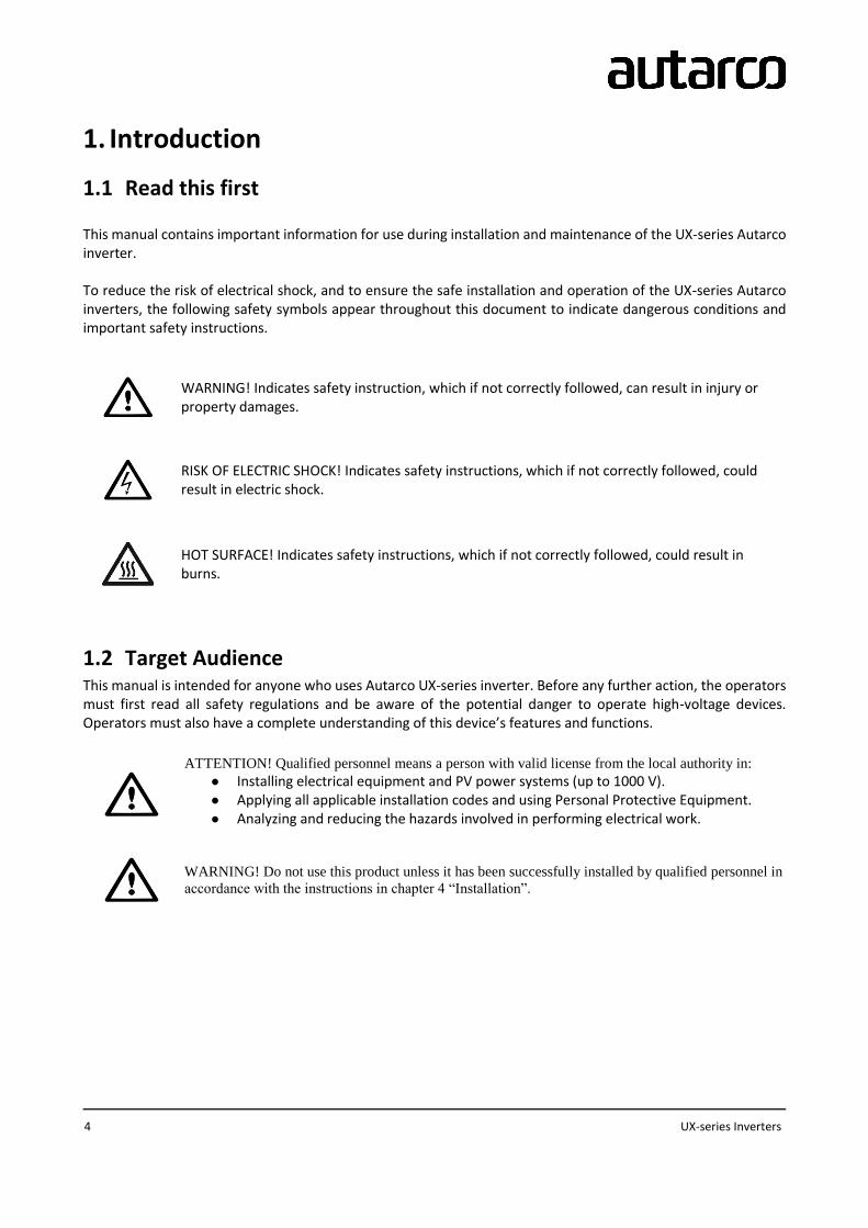
1.1 Read this first This manual contains important information for use during installation and maintenance of the UX-series Autarco inverter. To reduce the risk of electrical shock, and to ensure the safe installation and operation of the UX-series Autarco inverters, the following safety symbols appear throughout this document to indicate dangerous conditions and important safety instructions.
WARNING! Indicates safety instruction, which if not correctly followed, can result in injury or property damages.
RISK OF ELECTRIC SHOCK! Indicates safety instructions, which if not correctly followed, could result in electric shock.
HOT SURFACE! Indicates safety instructions, which if not correctly followed, could result in burns.
1.2 Target Audience This manual is intended for anyone who uses Autarco UX-series inverter. Before any further action, the operators must first read all safety regulations and be aware of the potential danger to operate high-voltage devices. Operators must also have a complete understanding of this device’s features and functions.
ATTENTION! Qualified personnel means a person with valid license from the local authority in:
● Installing electrical equipment and PV power systems (up to 1000 V). ● Applying all applicable installation codes and using Personal Protective Equipment. ● Analyzing and reducing the hazards involved in performing electrical work.
WARNING! Do not use this product unless it has been successfully installed by qualified personnel in
accordance with the instructions in chapter 4 “Installation”.

Installation and operation manual
IM-S2-UX-EN-V1.0 5
1.3 Product versions covered by this document The main purpose of this user manual is to provide instructions and detailed procedures for installing, operating, maintaining, and troubleshooting the UX-series of Autarco inverters which includes the following models:
● S2.UX40000(S)
● S2.UX50000(S)
● S2.UX50000-HV(S)
● S2.UX60000-HV(S)
● S2.UX70000-HV(S)
The “S2.” In the product code means the product is a grid-tied inverter.
The item code or SKU will include an additional number at the end. The final number references the default grid
standard and colour of inverter. For example, S2.UX50000S.1 is the 50kW model with Dutch grid standard as
default and Autarco blue cover.
If the product has an “S” at the end it comes with integrated DC switches.
Please keep this user manual available at all times in case of emergency.
2. Preparation
2.1 Safety instructions
DANGER! Do not touch any internal components whilst the inverter is in operation.
DANGER! Do not stand close to the inverter during severe weather conditions such as lighting,
etc.
Make sure you completely cover the surface of all PV arrays with opaque (dark) material before
wiring them or make sure the DC circuit breaker or equivalent DC isolator is disconnected.
This is because photovoltaic (PV) arrays create electrical energy when exposed to light, and could
cause a hazardous condition.
The UX series inverter must only be operated with PV arrays of protection class II, in accordance with IEC 61730, class A.

6 UX-series Inverters
WARNING! The PV inverter will become hot during operation; please don’t touch the heat sink or
peripheral surface during or shortly after operation.
NOTICE! Do not directly connect AC output of the inverter to any private AC equipment. The PV
inverter is designed to feed AC power directly into the public utility power grid.
WARNING! The installation, service, recycling and disposal of the inverters must be performed by
qualified personnel in compliance with national and local standards and regulations.
Please contact your dealer to get the information of authorized repair facility for any maintenance or
repairmen.
Any unauthorized actions including modification of product functionality of any form will affect the validation of warranty service; Autarco may deny the obligation of warranty service accordingly.
2.2 Package contents
Autarco UX-series inverter Mounting bracket
+ screws
12xMC4 connector pairs
(S4.MC4F/MC4M)
Instruction manual
2.3 Internal DC switch Please verify whether your Autarco UX-series inverter is equipped with internal DC switches. This switch can be found on the bottom of the inverter. If there isn’t an internal DC switch it is important to apply an external DC disconnector in order to completely disconnect the solar PV module strings from the inverter.
2.4 Explanations of symbols on inverter
10min
DANGER - HIGH ELECTRIC VOLTAGE This device is directly connected to public grid. All work to the inverter shall be carried out by qualified personnel only. There might be residual currents in inverter for up to 10 minutes because of large capacitors.
ATTENTION This device is directly connected to electricity DC generators and the public AC grid.

Installation and operation manual
IM-S2-UX-EN-V1.0 7
DANGER – HOT SURFACES The components inside the inverter will get hot during operation, DO NOT touch aluminum housing during operating.
ATTENTION In case of any work to the inverter, always refer to this manual for detailed product information.
ATTENTION This device SHALL NOT be disposed of in residential waste. Please go to Chapter 9 “Recycling and Disposal” for proper treatments.
CE MARK This equipment conforms to the basic requirements of the EU guideline governing low voltage and electromagnetic compatibility.
3. Product information
3.1 Overview Autarco UX-series grid tied inverters are state of the art, high efficiency, robust and reliable grid tied inverters at the best price quality ratio available. They are easy to install and carry a standard 10 year product warranty. Our rigorous quality control and testing facilities guarantee Autarco inverters meet the highest quality standards possible. These inverters are the key to our international track record of delivering extremely reliable solar power solutions. Key features:
● Maximum efficiency of 98.8%
● Wide MPPT voltage range
● Low turn off voltage
● High enclosure protection class IP65
● Intelligent redundant fan-cooling
● Standard ten year product warranty
● Multiple monitoring options
● Optional integrated DC switch
For full specifications please see chapter 11 “Product specifications”.
3.2 Product identification You can identify the inverter by the serial number (S/N) sticker on the side of the inverter. Important electrical specification can also be found on the label which can be found on the right side of the inverter housing. Do not remove the label or the serial number as this voids the product warranty.

8 UX-series Inverters
3.3 Product overview
A: Inverter cover B: LED light – POWER C: LED light – OPERATION D: LED light – ALARM E: LCD display 2x16 characters F: Escape key G: Up key H: Down key I: Enter key J: DC switches (optional) K: DC inputs MPPT 1-4 L: External Intelligent Fans M: Communication ports N: AC terminal block and cover
B C D
E
F G H I
J K L M N

Installation and operation manual
IM-S2-UX-EN-V1.0 9
4. Installation
4.1 Safety
DANGER! Do not install the inverter near flammable or explosive items.
WARNING! The installation must be performed by qualified personnel and in compliance with
national and local standards and regulations.
This inverter will be connected to a high voltage DC power generator and AC grid. Inappropriate
installation may also jeopardize the life span of the inverter.
The installation site must have good ventilation conditions. Direct exposure to intense sunshine is not
recommended.
4.2 Appropriate Mounting Location
The heat sink can reach a temperature of 75⁰C under operation.
● Make sure the mounting wall is strong enough to hold the weight of the inverter. ● The ambient temperature of installation site should be between -20 ⁰C and +60 ⁰C. ● Make sure of ample ventilation at installation site, insufficient ventilation may reduce the performance
of the electronic components inside the inverter and shorten the life span of the inverter. ● The inverter has fans that will intelligently cool the inverter if the internal components exceed 100⁰C.
The fan noise should not exceed 60dB.

10 UX-series Inverters
4.3 Mounting instructions
Two people are required to remove the inverter from the carton and install the inverter.
Handles are formed into the heatsink for ease of handling the inverter.
● The inverter is suitable for outdoor and indoor installation. ● Vertical installation is recommended, with a maximum inclination of 15⁰ backwards.
Max. 15⁰

Installation and operation manual
IM-S2-UX-EN-V1.0 11
4.4 Safety clearance
CAUTION! Make sure heat sinks are out of reach of children.
WARNING! When installing multiple inverters, make sure there is sufficient clearance between them. High temperatures may affect performance.
Observe the following minimum clearances to walls and other inverters
Min. 500mm Min. 500mm
Min. 500mm
Min. 500mm
12 UX-series Inverters
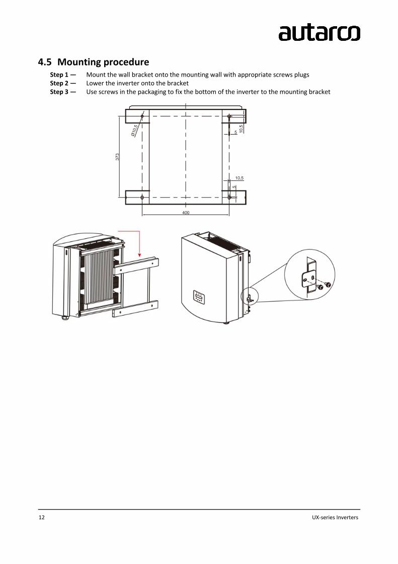
4.5 Mounting procedure Step 1 — Mount the wall bracket onto the mounting wall with appropriate screws plugs Step 2 — Lower the inverter onto the bracket Step 3 — Use screws in the packaging to fix the bottom of the inverter to the mounting bracket

Installation and operation manual
IM-S2-UX-EN-V1.0 13
5. Electrical installation
DANGER! This inverter will be connected to a high voltage DC power generator and AC grid. The installation must be performed by qualified personnel and in compliance with national and local standards and regulations
5.1 Grounding There are two options for ground protection: through grid terminal connection and external heat sink connection. If AC terminal is used to connect ground, please refer to the contents of 5.3.2. If the heat sink is used to connect the ground, please follow the steps below. 1) Prepare the grounding cable: recommended to use the 16-35mm² outdoor copper-core cable. 2) Prepare OT terminals M6
IMPORTANT! For multiple inverters in parallel, all inverters should be connected to the same ground point to eliminate the possibility of a voltage potential existing between inverters grounds.
WARNING! No matter what kind of grounding connection is adopted, it is strictly forbidden to connect the ground of the inverter with the lightning protection of the building, otherwise Autarco will not be responsible for any damage caused by lightning.
3) Strip the grounding cable insulation to the suitable length as shown in Figure 5.7.
IMPORTANT! B (insulation stripping length) is 2-3mm longer than A (OT cable terminal crimping area)

14 UX-series Inverters
4) Insert the stripped wire into the OT terminal crimping area, and use the hydraulic clamp to crimp the
terminal to the wire (as shown in Figure 5.8).
IMPORTANT! After crimping the terminal to the wire, inspect the connection to ensure the terminal is solidly crimped to the wire.
5) Remove the screw from the heat sink ground point 6) Use the screw of the ground point to attach the grounding cable. Tighten the screw securely. Torque is 3Nm (as shown as in Figure 5.9).
IMPORTANT! In order to improve the corrosion resistance of the grounding terminal, we recommend that the external grounding terminal is coated with silica gel or paint for protection after installation of the grounding cable.

Installation and operation manual
IM-S2-UX-EN-V1.0 15
5.2 AC connection
DANGER! Never connect or disconnect the connectors under load.
NOTICE! The AC connection to the electrical distribution grid must be performed only after receiving authorization from the utility that operates the grid.
The AC cable used must be dimensioned in accordance with any local and national directives on cable dimensions which specify requirements for the minimum conductor cross-section. Cable dimensioning factors are e.g.: nominal AC current, type of cable, type of routing, cable bundling, ambient temperature and maximum specified line losses. We recommend 16- 35mm2 105 ℃ cable with resistance lower than 1.5 ohm. Please make sure the resistance of cable is lower than 1.5 ohm. If the wire is longer than
20m, it's recommended to use 25-35mm cable. Refer to local electrical codes for wire sizing.
NOTE: There is no need to connect N to AC side for the UX series three-phase inverter, the ground wire can be connected to the grounding hole on the right side of the inverter heat sink.
Cable specification Copper-cored
cable
Copper clad
aluminum /
Aluminum Alloy
cable
Traverse cross sectional area (mm2 ) Range 16~35 25~35
Recommended 25 35
Cable outer diameter (mm) Range 22~32
Recommended 27
NOTE: Prepare M6 OT terminals
The steps to assemble the AC grid terminals are listed as follows:
A) Strip the end of AC cable insulating jacket about 90mm then strip the end of each wire (as shown in figure
5.17).

16 UX-series Inverters
Figure 5.17 Strip AC cable
NOTE: L2 (insulation stripping length) is 2mm-3mm longer than L1 (OT cable terminal
crimping area)
B) Strip the insulation of the wire core, insert into the cable crimping area of the OT terminal, then use a
hydraulic crimp tool to crimp it firmly. The wire must be covered with heat shrinkable tube or insulating tape.
When using the heat shrinkable tube sleeve the heat shrinkable tube over the wire before crimping the OT
terminal.
C) Remove the 4 screws on the AC terminal cover and remove the cover.
D) Remove the screw under terminal slide and pull out the terminal.
E) Insert the cable through cap nut, water proof bushing and AC terminal cover into the AC terminal and use a
socket wrench to tight the screws. The torque is 4-6Nm (as shown in figure 5.20).
L2 L1
Installation and operation manual
IM-S2-UX-EN-V1.0 17
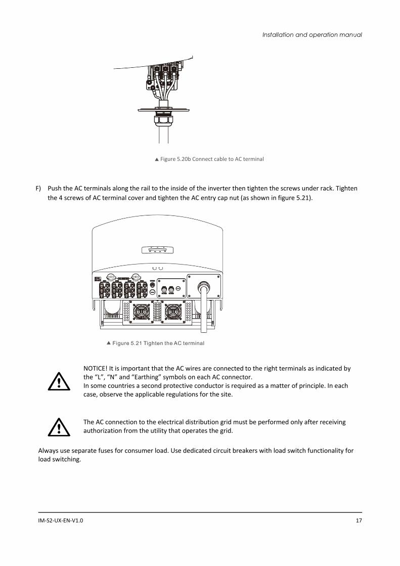
Figure 5.20b Connect cable to AC terminal
F) Push the AC terminals along the rail to the inside of the inverter then tighten the screws under rack. Tighten
the 4 screws of AC terminal cover and tighten the AC entry cap nut (as shown in figure 5.21).
NOTICE! It is important that the AC wires are connected to the right terminals as indicated by the “L”, “N” and “Earthing” symbols on each AC connector. In some countries a second protective conductor is required as a matter of principle. In each case, observe the applicable regulations for the site.
The AC connection to the electrical distribution grid must be performed only after receiving authorization from the utility that operates the grid.
Always use separate fuses for consumer load. Use dedicated circuit breakers with load switch functionality for load switching.

18 UX-series Inverters
DANGER! No consumer load should be applied between the mains circuit breaker and the inverter.
5.3 Additional Protections To protect the inverter's AC grid connection conductors, Autarco recommends installing breakers that will protect against overcurrent. The following table defines OPCD ratings for each model;
Inverter Rate Voltage (V) Rated Output (kW) OPCD: Current for
protection device (A)
S2.UX40000(S) 400V 40 80
S2.UX50000(S) 400V 50 100
S2.UX50000-HV(S) 480/500V 50 80
S2.UX60000-HV(S) 480/500V 60 80
S2.UX70000-HV(S) 540V 70 90
The Autarco inverter is equipped with an integrated Residual Current Protective Device (RCPD) and Residual Current Operated Monitor (RCOM). The RCOM will detect the leakage current and compare it with the expected value, if the leakage current exceeds the permitted range, the RCPD will disconnect the inverter from the AC load. If regulations in the country of installation stipulate an external Residual Current Device (RCD), you must use a device with a tripping threshold of 100 mA or more. A type “A” RCD can be used in accordance with our “Manufacturer’s declaration for usage of residual current devices with Autarco SX, UX and LX grid-tied inverters.”
5.4 DC connections
DANGER! Never connect or disconnect the connectors under load.
UX-series inverters have four MPP trackers. The DC characteristics of each model is shown in the table below:
Inverter MPP trackers Max DC power Max DC voltage Max. DC current per
MPPT
UX40000(S)
4
48000W
1100V
22.0A
UX50000(S) 55000W 28.5A
UX50000-HV (S) 55000W 22.0A
UX60000-HV (S) 66000W 28.5A
UX70000-HV(S) 77000W

Installation and operation manual
IM-S2-UX-EN-V1.0 19
DANGER! Do not connect the strings with an open circuit voltage greater than the Max DC voltage of the inverter.
To connect the PV generator to the inverters we use 4mm² or 6mm² PV cable and MC4 connectors. For details on how to assemble MC4 connector please refer our MC4 connector manual.
DANGER! For protection against electric shock, MC4 connectors must be isolated from the PV array while being assembled or disassembled.
DC connections must not be unplugged while under load. They can be placed in a no-load state by switching off the DC/AC converter or breaking the DC circuit interrupter. Plugging while under voltage is permitted.
CAUTION! MC4 connectors are watertight IP67 but cannot be used permanently under water. Do not lay the MC4 connectors directly on the roof surface.
If any tools or parts are used in the MC4 connector assembly other than those listed in the MC4 connector manual, neither safety nor compliance with the technical data can be guaranteed.
5.5 Inverter commissioning sequence
Turn ON Turn OFF
1. Connect AC side (if not connected yet)
2. Connect DC side (if not connected yet)
3. Switch ON both the DC switches
4. Switch ON the AC switch
1. Switch OFF the AC switch
2. Switch OFF both the DC switches
6. Operation
6.1 LED indicator lights There are three LED status indicator lights in the front panel of UX series inverters. The left POWER light (red) indicates power status of the inverter. The middle OPERATION light (green) indicates the operation status. The right ALARM light (yellow) indicates the alarm status. Table 3.1 explains their meanings.

20 UX-series Inverters
Light Status Description
POWER (red) ON The PV array provides power to the inverter
OFF The PV array does not provide power to the inverter
OPERATION (green)
ON The inverter is feeding AC power to the grid
OFF The inverter is not feeding AC power to the grid
FLASHING The inverter is initializing
ALARM (yellow)
ON There is a fault. Refer to the inverter display and chapter 10
of this manual for details
OFF The inverter is operating normally
When inverter DC switch and AC switch have been turned on the inverter will start initializing. After approx. 3 minutes the inverter will start normal operation with the inverter display showing GENERATING.
6.2 Inverter display
NOTICE! During normal operation, make sure the optional integrated DC switch is switched “on”.
The display content consists of 2 lines. During regular operation the display shows the current power and operation status alternatively for 10 seconds. Pressing the UP or DOWN buttons will manually cycle through these two displays. Pressing the ENTER button gives access to the main menu which has four sub menus:
● Information, described in detail in chapter 6.3. ● Settings, described in detail in chapter 6.4. ● Advanced information, described in detail in chapter 6.5. ● Advanced settings, described in details in chapter 6.6.
By pressing UP or DOWN keys you can cycle through these sub menus and click ENTER to go into the submenu.
6.3 Information The UX series inverters main menu provides access to operational data and information. The information is displayed by selecting "Information" from the main menu.
6.3.1 Pausing on information
By default the inverter display will scroll through the information states below. You can also press UP or DOWN keys to manually scroll through. Pressing the ENTER key will lock or unlock the current display.
(locked) (scrolling)
By pressing the ESC key returns to the main menu.
State Description
V_DC1 %VALUE% Shows the input voltage (V) of the MPPT1

Installation and operation manual
IM-S2-UX-EN-V1.0 21
I_DC1 %VALUE% A Shows the input current (A) of the MPPT1
V_DC2 %VALUE%
I_DC2 %VALUE% A
Shows the input voltage (V) of the MPPT2
Shows the input current (A) of the MPPT2
V_DC3 %VALUE%
I_DC3 %VALUE% A
Shows the input voltage (V) of the MPPT3
Shows the input current (A) of the MPPT3
V_DC4 %VALUE%
I_DC4 %VALUE% A
Shows the input voltage (V) of the MPPT4
Shows the input current (A) of the MPPT4
V_A %VALUE%
I_A %VALUE% A
Shows the voltage (V) of the grid L1
Shows the current (A) of the grid L1
V_B %VALUE%
I_B %VALUE% A
Shows the voltage (V) of the grid L2
Shows the current (A) of the grid L2
V_C %VALUE%
I_C %VALUE% A
Shows the voltage (V) of the grid L3
Shows the current (A) of the grid L3
Status: %VALUE%
Power: %VALUE% W
Shows the status of the inverter
Shows current output power (W) of the inverter
For any status other than “Generating” and “Initializing” please refer to chapter 10
for troubleshooting
Rea_Power: %VALUE% Var
App_Power: %VALUE% VA
Shows the real power generated
Shows the apparent power generated
Grid frequency
F_Grid %VALUE% Hz Shows current frequency (Hz) of the grid
Total Energy
%VALUE% kWh Shows total energy output (kWh)
This Month: %VALUE% kWh
Last Month: %VALUE% kWh
Total energy output in this month (kWh)
Total energy output of last month (kWh)
Today: %VALUE% kWh
Yesterday: %VALUE% kWh
Total energy output in this day (kWh)
Total energy output of yesterday (kWh)
Inverter S/N Serial ID of the inverter
Work Mode:
DRM Number:
Demand response mode (only relevant for some markets)
The demand response number (1-8) of the inverter
6.4 Settings The following options are available under the Settings submenu:
Set Time and Date
Press UP/DOWN keys to set change element
Press ENTER key to move to next element
Press ESC key to save date and return

22 UX-series Inverters
Set Address
Assign a number (##) to the inverter to distinguish between multiple inverters when
using parallel communication with WIFI-BOX or GPRS-BOX
Press UP/DOWN keys to set change number
Press ENTER key to save the setting
Press ESC key to return.
Changing the Address when using WIFI-STICK or LAN-
STICK may result in monitoring to stop working.
Restore Settings Delete alarm messages that have been generated
6.5 Advanced info
WARNING! Access to this section of the menu is for Autarco qualified and accredited technicians
only. Unauthorized access will void the product and system warranty.
Screen can be scrolled through with UP/DOWN keys to see the information as per the table below. Press ENTER key to enter a submenu. Press ESC key to go back to the main menu.
Alarm Messages
The display shows the 100 latest alarm messages (see Figure 7.6).
Press UP/DOWN keys to cycle through alarm messages
Press ESC key to return
Running Message This function is for maintenance personnel to get running message such as
internal temperature, Standard NO. etc.
Screens can be scrolled manually by pressing the UP/DOWN keys.
Version The screen shows the operating software version of the inverter
Daily Energy
The function is for checking the energy generation for selected day.
Press DOWN key to move the cursor to day, month and year, press UP key to
change the digit.
Press ENTER after the date is fixed.
Press UP/DOWN key to move one date from another.
Monthly Energy
The function is for checking the energy generation for selected month.
Press DOWN key to move the cursor, press UP key to change the digit.
Press ENTER after the month/year is fixed.
Press UP/DOWN key to move one date from another.
Yearly Energy
The function is for checking the energy generation for selected year.
Press DOWN key to move the cursor, press UP key to change the digit.
Press ENTER after the month/year is fixed.
Press UP/DOWN key to move one date from another.
Daily Record The screen shows history of changing settings. Only for maintenance
personnel.
Communication data The screen shows information interpretable to qualified technicians only

Installation and operation manual
IM-S2-UX-EN-V1.0 23
Warning Message Internal data of the inverter
6.6 Advanced Settings
WARNING! Access to this section of the menu is for Autarco qualified and accredited technicians
only. Unauthorized access will void the product warranty and any kWh Guarantee.
Screen can be scrolled through with UP/DOWN keys to see the information as per the table below. Press ENTER key to enter a submenu. Press ESC key to go back to the main menu.
Select grid standard
WARNING! Set GRID OFF (see below) before changing this
setting.
Press UP/DOWN keys to cycle through available standards
Press ENTER key to save the setting - Press ESC key to cancel and return
When selecting User defined the following upper and lower values have to be
set for voltage and frequency:
OV-G-V1: 236---335V
OV-G-V1-T: 0.1---9s
OV-G-V2: 248---341V
OV-G-V2-T: 0.1---1s
UN-G-V1: 173---236V
UN-G-V1-T: 0.1---9s
UN-G-V2: 132---219V
UN-G-V2-T: 0.1---1s
OV-G-F1: 50.2-53Hz(60.2-63Hz)
OV-G-F1-T: 0.1---9s
OV-G-F2: 51-53Hz(61-63Hz)
OV-G-F2-T: 0.1---9s
UN-G-F1: 47-49.5Hz(57-59.5Hz)
UN-G-F1-T: 0.1---9s
UN-G-F2: 47-49Hz(57-59Hz)
UN-G-F2-T: 0.1---9s
Press UP/DOWN keys to scroll through these values
Press ENTER key to edit the selected value
Press UP/DOWN keys to change the selected value
Press ENTER key to save and return
Press ESC key to cancel and return
WARNING! Set GRID ON (see below) before new standard
is activated.
WARNING! Please note that the User-Def standard is not to
be used without the agreement of the local grid authority.

24 UX-series Inverters
Grid ON/OFF
Press UP/DOWN keys to cycle through grid ON/OFF options
Press ENTER key to save
Press ESC key to return
Clear Energy
Reset the inverters total kWh output to zero.
Using this function without previous approval from Autarco will void any existing kWh Guarantees.
New Password
Change the password to enter Advanced Info and Advanced Settings. Enter the
current password before setting a new password. Press the DOWN key to
move the cursor, Press the UP key to change the digit. Press the ENTER key to
execute the setting. Press the ESC key to return to the previous menu.
Power Control
Inverter output active power and reactive power control can be set through this
menu if the grid is unbalanced:
1. Set output power 2. Set reactive power 3. Out_P with restore
4. Rea_P with restore
5. Select PF curve
Calibrate Energy
Maintenance or replacement could clear or cause a different value for total
energy. Use this function to allow user to revise the value of total energy to the
same value as before.
Press the DOWN key to move the cursor, Press the UP key to revise the value.
Press the ENTER key to execute the setting. Press the ESC key to return to the
previous menu.
Special Settings
Special settings can switch off functions temporarily for testing purposes.
These tests should only be done by qualified Autarco personnel or trained
installers when requested to do so. Submenu includes:
1. Grid Filter Set 2. Relay_Protect Set 3. ILeak_Protect Set 4. GROUND_Protect Set 5. GRID INTF.02 Set 6. MPPT Parallel Mode
7. Cnst. Voltage Mode
8. L/FRT Set 9. IgZero_COMP. Set 10. PI Set 11. IgADCheckPRO Set 12. NoSmallPulse Set
STD Mode Settings
STD Mode Settings are used when demand response is required by grid
operators.
1. Working Mode Set
2. Power Rate Limit
3. Freq Derate Set
4. 10mins Voltage Set

Installation and operation manual
IM-S2-UX-EN-V1.0 25
5. Initial Settings
Restore Settings Restore Settings resets the inverter to factory defaults.
HMI Updater Selecting HMI Updater will show the current software version the LCD screen
is based on.
Reset HMI This function is used to reset the HMI software.
Debug parameter Shows debug parameters.
Fan test Test intelligent fan
Power parameter
This function is used to calibrate inverter output energy. It will not impact the
energy count for inverter with RGM.
Using this function without previous approval from Autarco will void any existing kWh Guarantees.
7. Monitoring setup and system registration The UX inverters have the following communication ports:
● COM1: Green 4 pin connector RS485 ● COM2 and COM3: Cable glands and cover with following connection points behind:
o 2 x RJ45 connections o 1 x RS485 terminal block
COM2 and COM3 are RJ-45 connectors suitable for connecting multiple inverters in daisy chain configuration and connecting them to a WIFI-box, GPRS-box or other data logger.

26 UX-series Inverters
7.1 The following products are available to monitor UX series inverters:
Product Port Communication Method
Connection To:
IOT Capability
# Inverters per product
Parallel Connection
S2.WIFI-STICK COM1 WIFI Router N 1 N
S2.WIFI-BOX COM2 & COM3
WIFI OR LAN Router N 10 Y, Cabled (RJ45)
S2.LAN-STICK COM1 Cabled (RJ45)
Router N 1 N
S2.ZWAVE-STICK
COM1 Z-wave Z-wave Gateway
Y 1 N
S2.GPRS-STICK COM1 Sim Data Cellular network
N 1 N
S2.GPRS-BOX COM2 & COM3
Sim Data Cellular network
N 10 Y, Cabled (RJ45)
PC or Data Logger
COM2 Terminal block
Local PC or Data Logger
N 1 N

Installation and operation manual
IM-S2-UX-EN-V1.0 27
Steps for using RJ45 connections for RS485 Communications:
1. Use a network wire stripper to strip the insulation layer off the communication cable. Using the standard wire sequence referenced in TIA/EIA 568B, separate the wires in the cable. Use a network cable tool to trim the wire. Flatten the wire in the order shown in the figure below.
2. Insert the wire into the RJ45 connector then crimp the connector with the crimping tool.
3. Remove the cap nut from the waterproof cable glands labeled COM2 and COM3 at the bottom of the
inverter. Remove the plug from the fitting.
4. Insert the RJ45 connector into the RJ45 port in the inverter maintenance chamber. 5. Replace the cap nuts for COM2/3 and tighten firmly.
Please refer to related instructions of communication products for further installation instructions.
Complete monitoring setup at my.autarco

28 UX-series Inverters
8. Maintenance
CAUTION! Do not touch the heat sink when the inverter is in operation. Turn OFF the inverter (see
section 5.5) and allow for cooling down before cleaning.
CAUTION! Never use any solvents, abrasives or corrosive materials to clean the inverter.
The UX-series inverters require general maintenance to be performed once per year. Impurities such as dust and dirt accumulation on the heat sink may negatively affect the inverter’s ability to dissipate heat. Any dirt or dust can be removed with a cloth or soft brunch.
If the fan does not work properly, the inverter will not be cooled effectively and inverter efficiency may be reduced. Broken fans should be replaced following process below:
①、Disconnect the AC power.
②、Turn the DC switch to "OFF" position.
③、Wait for 10 minutes at least.
4、 Remove the 4 screws on the fan plate and pull out the fan assembly slowly.

Installation and operation manual
IM-S2-UX-EN-V1.0 29
5、 Disconnect the fan connector carefully and take out the fan.
6、 Clean or replace the fan. Assemble the fan on the rack.
7、 Connect the electrical wire and reinstall the fan assembly. Restart the inverter.
9. Disposal To comply with European Directive 2002/96/EC on waste Electrical and Electronic Equipment and its implementation as national law, electrical equipment that has reached the end of its life must be collected separately and returned to an approved recycling facility. Ignoring this EU Directive may have severe effects on the environment and your health.
30 UX-series Inverters
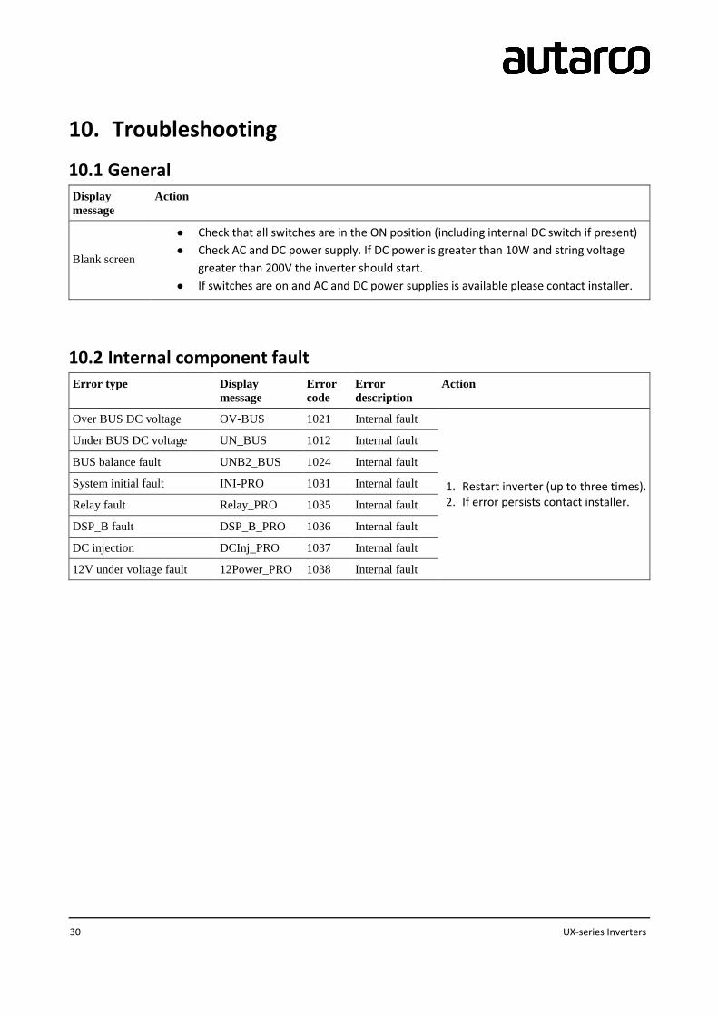
10. Troubleshooting
10.1 General
Display
message
Action
Blank screen
● Check that all switches are in the ON position (including internal DC switch if present)
● Check AC and DC power supply. If DC power is greater than 10W and string voltage
greater than 200V the inverter should start.
● If switches are on and AC and DC power supplies is available please contact installer.
10.2 Internal component fault
Error type Display
message
Error
code
Error
description
Action
Over BUS DC voltage OV-BUS 1021 Internal fault
1. Restart inverter (up to three times). 2. If error persists contact installer.
Under BUS DC voltage UN_BUS 1012 Internal fault
BUS balance fault UNB2_BUS 1024 Internal fault
System initial fault INI-PRO 1031 Internal fault
Relay fault Relay_PRO 1035 Internal fault
DSP_B fault DSP_B_PRO 1036 Internal fault
DC injection DCInj_PRO 1037 Internal fault
12V under voltage fault 12Power_PRO 1038 Internal fault

Installation and operation manual
IM-S2-UX-EN-V1.0 31
10.3 Grid errors
Error
type
Display
message
Error
code
Error
description Action
Over
voltage
OV-G-
V 1010
Grid
voltage
exceeds the
standard set
in the
inverter
1. Wait to see if the grid voltage returns within limits. 2. If problem persists, check whether the grid standard is set
correctly in Advanced Setting). 3. Check V_AC, grid voltage, in Information display of inverter (see
6.4) and perform independent measurement of grid voltage to confirm that the inverter reading is correct. If the measured voltage is outside the local grid standard limits, please contact your local utility as it may require monitoring and adjustment
4. With agreement from utility it is possible to set a user defined voltage range (see 6.7).
Under
voltage
UN-G-
V 1011
Grid
voltage is
below the
standard set
in the
inverter
Over
frequency OV-G-F 1012
Grid
frequency
exceeds the
standard set
in the
inverter.
1. Wait to see if the grid frequency returns within limits. 2. If a problem persists, check whether the grid standard is set
correct in Advanced Settings (see 6.7). 3. Check grid frequency, in Information display of inverter (see 6.4)
and perform independent measurement of grid frequency to confirm that the inverter reading is correct. If the measured frequency is outside the local grid standard limits, please contact your local utility as it may require monitoring and adjustment.
4. With agreement from utility it is possible to set a user defined frequency range (see 6.7).
Under
frequency
UN-G-
V 1013
Grid
frequency is
below the
standard set
in the
inverter.
Grid
impedance G-IMP 1014
High grid
impedance
1. Wait to see if the grid returns within limits. 2. If problem persists please contact your local utility as it may
require monitoring and adjustment.
No Grid NO
Grid 1015
The inverter
cannot
detect a
grid.
1. Check your AC power connections, fuses and switches. 2. Restart the inverter. 3. Call your local grid to resolve the black out.

32 UX-series Inverters
10.4 System and design fault
Error type Display
message
Error
code Error description Action
Over DC
voltage OV-DC 1020
The DC input of the solar
strings exceeds the
inverters limits.
1. Restart inverter (up to three times). 2. Contact installer to:
a. Perform independent measurement of string voltage to confirm that the inverter reading is correct.
3. Rewire strings so that string voltage is within accepted range.
Over
temperature TEM-PRO 1032
The internal temperature
of inverter exceeds limits.
1. Check location of inverter. Ensure it has adequate ventilation and is not exposed to direct sunlight.
2. Contact installer to replace inverter in case problem persists.
Short circuit
fault SHORT-PRO 1030
A short circuit has been
detected in the system.
1. Restart inverter (up to three times). 2. Call installer to:
a. Check for pinched, crimped or otherwise damaged cables and connections.
b. Check all switches for short circuit. 3. If error persists contact Autarco for replacement inverter.
Ground fault GROUND-
PRO 1033
Current flow detected
through ground conductor.
1. Restart inverter (up to three times). 2. Call installer to:
a. Check if there is any current on the ground conductor using a clamp meter.
b. Check for pinched, crimped or otherwise damaged cables and connections.
3. If error persists contact Autarco for replacement inverter.
Current
leakage ILeak_PRO 1034
A current leak has been
detected.
1. Restart inverter (up to three times). 2. Call installer to:
a. Check if there is any current on the ground conductor using a clamp meter.

Installation and operation manual
IM-S2-UX-EN-V1.0 33
b. Check for pinched, crimped or otherwise damaged cables and connections.
3. If error persists contact Autarco for replacement inverter.

34 UX-series Inverters
11. Product specifications
UX40000(S) UX50000(S) UX50000-HV UX60000-HV UX70000-HV
Input
Max. DC voltage (V) 1100
MPPT voltage range (V) 200-1000
Turn on voltage (V) 200
Turn off voltage (V) 200
Number of MPP trackers 4
Max. DC current per MPPT (A) 22.0 28.5 22.0 28.5 28.5
Number of DC connections per MPPT 3
Total number of strings 12
DC connection type MC4
Output
Nominal AC power (W) 40000 50000 50000 60000 70000
Max. AC power (W) 44000 50000 55000 66000 77000
Nominal AC current (A) 58.0 72.2 60.2/57.7 72.2/69.3 74.8
Max. AC current (A) 66.9 83.3 66.2 80 82.3
Power connection Three phase
Grid voltage range According to EN50438 VDE 0126-1-1, UL1741, G59/3, AS4777
Grid frequency range According to EN50438 VDE 0126-1-1, UL1741, G59/3, AS4777

Installation and operation manual
IM-S2-UX-EN-V1.0 35
Power factor (at rated output power) 0.8 …1… 0.8
Harmonic distortion at nominal output <3%
AC connector OT Terminal connectors
Overvoltage category OVC II
I (MAINS), OVC II (PV)
Power consumption
Nighttime power consumption (W) < 1
Standby power consumption (W) 6
Efficiencies
Max. efficiency >98.8% >99.0%
Euro efficiency >98.4% >98.5%
MPPT efficiency 99.9% 99.9%
UX40000(S) UX50000(S) UX50000-HV UX60000-HV UX70000-HV
Safety protection
Internal overvoltage protection Yes
DC Insulation monitoring Yes
Earth fault protection Yes
Grid monitoring According to VDE 0126-1-1, UL1741, G83/2, AS4777
Earth fault current monitoring According to VDE 0126-1-1, UL1741, G83/2, AS4777
DC current monitoring According to VDE 0126-1-1, UL1741, G83/2, AS4777
Islanding protection According to VDE 0126-1-1, UL1741, G83/2, AS4777
CE- compliant According to EN61000-6-2, EN61000-6-4, AS3100, IEC62109

36 UX-series Inverters
General data
Dimensions (W x H x D) (mm) 630 x 700 x 357
Weight 63kg 68kg
Installation environment Indoor or outdoor
Mounting Wall bracket
Operating temperature range (°C) -25°C to 60°C
Max. relative humidity 100%
Maximum altitude 4000m
IP protection rating IP65 according to EN60529
Isolation type Transformerless
Cooling concept
Natural
convection
Intelligent
redundant fan-
cooling
Natural
convection
Intelligent
redundant fan-cooling
Noise level (dB) < 30 < 60 < 30 < 60
LED indicators 3
LCD display 16 x 2 character
Communication interfaces 4 pins RS485 connector 2 RJ45 connector 2 group of terminal block
Optional interfaces Wi-Fi 802.11, RS232, RJ45, GPRS
Standard warranty 10 years
Integrated DC switch Optional