installation and operation manual - wood...
TRANSCRIPT

Tel +1.360.650.1111
Fax +1.360.650.1166
www.woodstone-corp.com
WOOD STONE CORPORATION1801 W. Bakerview Rd.
Bellingham, WA 98226 USA
PHOENIX OVENStone Hearth Oven
Gas-Fired, Gas/Wood Combination Models
PHOENIX 3030 WS-PX-3030-RFG
PHOENIX 4343 WS-PX-4343-RFG-(W)
PHOENIX 4355 WS-PX-4355-RFG-(W)
PHOENIX 4836 WS-PX-4836-RFG
DOC NO M0029.09 REVISED SEPTEMBER 2017
Installation and Operation Manual
Phoenix Installation and Operation Manual
PG 2 OF 40
M0029.09 SEPTEMBER 2017
An ongoing program of product improvement may require us to change specifications without notice.
WOOD STONE CORPORATION1801 W. Bakerview Rd.Bellingham, WA 98226 USA
TEL +1.360.650.1111FAX +1.360.650.1166
E-MAIL [email protected]
TABLE OF CONTENTS
TABLE OF CONTENTS
Phoenix � � � � � � � � � � � � � � � � � � 3
Cautions & Warnings � � � � � � � � � 4
SPECIFICATIONS
PX-3030 � � � � � � � � � � � � � � � � 5
PX-4343 � � � � � � � � � � � � � � � � 6
PX-4355 � � � � � � � � � � � � � � � � 7
PX-4836 � � � � � � � � � � � � � � � � 8
Installation Clearances � � � � � � � � 9
Moving & Placing the Oven� � � � � 10
Venting � � � � � � � � � � � � � � � � � 11
Lifting the Oven � � � � � � � � � � � � 12
Exploded Parts Diagram � � � � � � 14
Assembly � � � � � � � � � � � � � � � 15
Utility Connections � � � � � � � � � � 21
Installation Clearances � � � � � � � 23
Storage Box Installation � � � � � � � 24
Disassembly � � � � � � � � � � � � � � 25
Controller � � � � � � � � � � � � � � � 27
Initial Start-Up � � � � � � � � � � � � � 28
Daily Operation � � � � � � � � � � � � 29
Maintenance � � � � � � � � � � � � � 30
Troubleshooting Guide� � � � � � � � 31
Wood Burning � � � � � � � � � � � � � 32
Fuelwood Facts � � � � � � � � � � � � 34
100-120 VAC Wire Diagram � � � � 35
200-240 VAC Wire Diagram � � � � 37
Limited Warranty � � � � � � � � � � � 39
Phoenix Installation and Operation Manual
PG 3 OF 40
M0029.09 SEPTEMBER 2017
An ongoing program of product improvement may require us to change specifications without notice.
WOOD STONE CORPORATION1801 W. Bakerview Rd.Bellingham, WA 98226 USA
TEL +1.360.650.1111FAX +1.360.650.1166
E-MAIL [email protected]
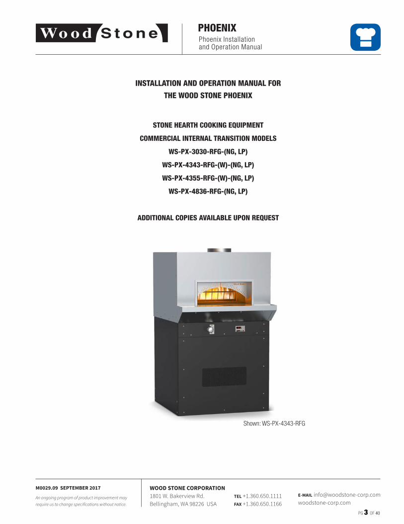
PHOENIX
INSTALLATION AND OPERATION MANUAL FOR
THE WOOD STONE PHOENIX
STONE HEARTH COOKING EQUIPMENT
COMMERCIAL INTERNAL TRANSITION MODELS
WS-PX-3030-RFG-(NG, LP)
WS-PX-4343-RFG-(W)-(NG, LP)
WS-PX-4355-RFG-(W)-(NG, LP)
WS-PX-4836-RFG-(NG, LP)
ADDITIONAL COPIES AVAILABLE UPON REQUEST
Shown: WS-PX-4343-RFG
Phoenix Installation and Operation Manual
PG 4 OF 40
M0029.09 SEPTEMBER 2017
An ongoing program of product improvement may require us to change specifications without notice.
WOOD STONE CORPORATION1801 W. Bakerview Rd.Bellingham, WA 98226 USA
TEL +1.360.650.1111FAX +1.360.650.1166
E-MAIL [email protected]
CAUTIONS & WARNINGS
WOOD STONE PHOENIX GAS OVEN
INSTALLATION AND OPERATING INSTRUCTIONS
DO NOT THROW THIS MANUAL AWAY
IT IS RECOMMENDED THAT THIS OVEN BE INSTALLED, MAINTAINED AND SERVICED BY AUTHORIZED PROFESSIONALS.
IMPORTANT: Consult your local gas supplier for a statement outlining a procedure to be followed in the event you smell gas. Post the statement in a prominent location.
RETAIN THIS MANUAL FOR FUTURE REFERENCEAdditional copies of this manual are available at woodstone-corp�com�
For prompt responses to service/maintenance questions, call your local distributor�
FOR YOUR SAFETY: Do not store or use gasoline or other flammable vapors or liquids in the vicinity of this or any other appliance.
WARNING: Improper installation, adjustment, alteration, service or maintenance can result in property damage, injury or death. Read the installation, operation and maintenance instructions thoroughly before installing or servicing this equipment.
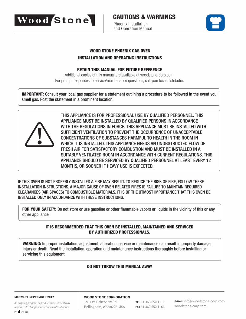
IF THIS OVEN IS NOT PROPERLY INSTALLED A FIRE MAY RESULT. TO REDUCE THE RISK OF FIRE, FOLLOW THESE INSTALLATION INSTRUCTIONS. A MAJOR CAUSE OF OVEN RELATED FIRES IS FAILURE TO MAINTAIN REQUIRED CLEARANCES (AIR SPACES) TO COMBUSTIBLE MATERIALS. IT IS OF THE UTMOST IMPORTANCE THAT THIS OVEN BE INSTALLED ONLY IN ACCORDANCE WITH THESE INSTRUCTIONS.
THIS APPLIANCE IS FOR PROFESSIONAL USE BY QUALIFIED PERSONNEL. THIS APPLIANCE MUST BE INSTALLED BY QUALIFIED PERSONS IN ACCORDANCE WITH THE REGULATIONS IN FORCE. THIS APPLIANCE MUST BE INSTALLED WITH SUFFICIENT VENTILATION TO PREVENT THE OCCURRENCE OF UNACCEPTABLE CONCENTRATIONS OF SUBSTANCES HARMFUL TO HEALTH IN THE ROOM IN WHICH IT IS INSTALLED. THIS APPLIANCE NEEDS AN UNOBSTRUCTED FLOW OF FRESH AIR FOR SATISFACTORY COMBUSTION AND MUST BE INSTALLED IN A SUITABLY VENTILATED ROOM IN ACCORDANCE WITH CURRENT REGULATIONS. THIS APPLIANCE SHOULD BE SERVICED BY QUALIFIED PERSONNEL AT LEAST EVERY 12 MONTHS, OR SOONER IF HEAVY USE IS EXPECTED.
!
Phoenix Installation and Operation Manual
PG 5 OF 40
M0029.09 SEPTEMBER 2017
An ongoing program of product improvement may require us to change specifications without notice.
WOOD STONE CORPORATION1801 W. Bakerview Rd.Bellingham, WA 98226 USA
TEL +1.360.650.1111FAX +1.360.650.1166
E-MAIL [email protected]
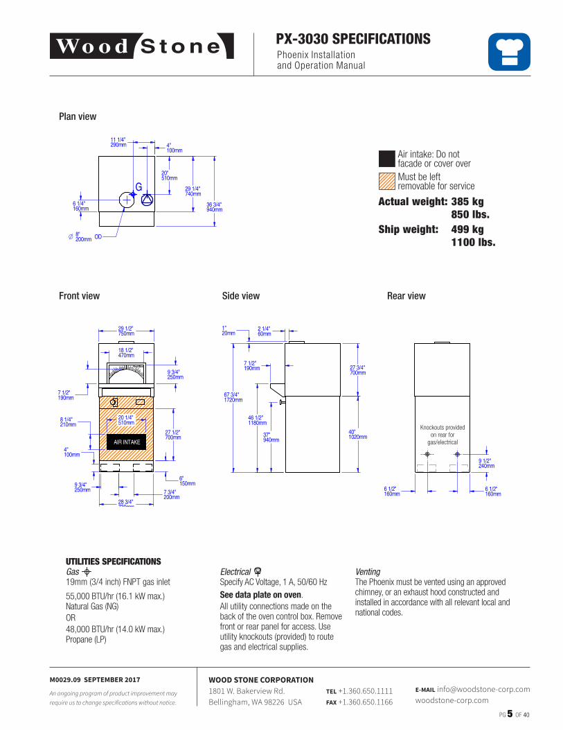
PX-3030 SPECIFICATIONS
ElectricalSpecify AC Voltage, 1 A, 50/60 HzSee data plate on oven�All utility connections made on the back of the oven control box� Remove front or rear panel for access� Use utility knockouts (provided) to route gas and electrical supplies�
VentingThe Phoenix must be vented using an approved chimney, or an exhaust hood constructed and installed in accordance with all relevant local and national codes�
UTILITIES SPECIFICATIONSGas19mm (3/4 inch) FNPT gas inlet
55,000 BTU/hr (16�1 kW max�) Natural Gas (NG)OR48,000 BTU/hr (14�0 kW max�) Propane (LP)
Actual weight: 385 kg 850 lbs.Ship weight: 499 kg 1100 lbs.
Plan view
Side view Rear viewFront view
Knockouts provided on rear for
gas/electrical
Air intake: Do not facade or cover overMust be leftremovable for service
REV:
LEGEND:
PART #: WS-BL-3030-RFG
Bistro Commercial Series - 3030General Arrangement
4/19/2013 bena 2DWN BY:SHEET:
Bellingham, WA 360/650-1111 www.woodstone-corp.com
DIMENSIONS ARE IN INCHESTOLERANCES: LINEAR ±1/2 [±10mm], ANGULAR ±2°
UNLESS NOTED OTHERWISE
\\woodstone.net\dfs\CAD\0 Pn\WS Top Level\WS-BL-3030_General_Arrangement-2.dft
THE INFORMATION CONTAINED IN THIS DRAWING IS THESOLE PROPERTY OF WOOD STONE CORPORATION
ANY REPRODUCTION OR USE IN PART OR AS A WHOLEWITHOUT THE WRITTEN PERMISSION OF WOOD STONE IS
PROHIBITED
AN ONGOING PROGRAM OF PRODUCT IMPROVEMENTMAY REQUIRE US TO CHANGE SPECIFICATIONS
WITHOUT NOTICE.
DATE:
G
120VAC, 4A
GAS INLET: 3/4" NPT
55,000 BTU, NG
42,000 BTU, LP
1 of 1
AIR INTAKE
G
36 3/4"940mm
6 1/4"160mm
O 8"200mm OD
6 1/2"160mm
6 1/2"160mm
27 3/4"700mm
37"940mm
46 1/2"1180mm
7 1/2"190mm
67 3/4"1720mm
2 1/4"60mm
1"20mm
18 1/2"470mm
9 3/4"250mm
7 1/2"190mm
4"100mm
29 1/2"750mm
29 1/4"740mm
27 1/2"700mm
28 3/4"730mm
6"150mm
7 3/4"200mm
9 3/4"250mm
40"1020mm
9 1/2"240mm
20 1/4"510mm
8 1/4"210mm
11 1/4"290mm 4"
100mm
20"510mm
Phoenix Installation and Operation Manual
PG 6 OF 40
M0029.09 SEPTEMBER 2017
An ongoing program of product improvement may require us to change specifications without notice.
WOOD STONE CORPORATION1801 W. Bakerview Rd.Bellingham, WA 98226 USA
TEL +1.360.650.1111FAX +1.360.650.1166
E-MAIL [email protected]
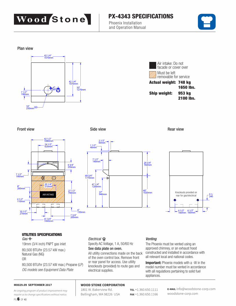
PX-4343 SPECIFICATIONS
UTILITIES SPECIFICATIONSGas 19mm (3/4 inch) FNPT gas inlet
80,500 BTU/hr (23�57 kW max�) Natural Gas (NG)OR
80,500 BTU/hr (23�57 kW max�) Propane (LP)OG models see Equipment Data Plate
Actual weight: 748 kg 1650 lbs.Ship weight: 953 kg 2100 lbs.
Plan view
Side view Rear viewFront view
Air intake: Do not facade or cover overMust be leftremovable for service
Knockouts provided on rear for gas/electrical
REV:
LEGEND:
PART #: Bistro Commercial Series - 4343
Bistro Commercial Series - 4343 General Arrangement
9/17/2013 bena 1DWN BY:SHEET:
Bellingham, WA 360/650-1111 www.woodstone-corp.com
DIMENSIONS ARE IN INCHESTOLERANCES: LINEAR ±1/2 [±10mm], ANGULAR ±2°
UNLESS NOTED OTHERWISE
\\woodstone.net\dfs\CAD\0 Pn\WS Top Level\WS-BL-4343_General_Arrangement-1.dft
THE INFORMATION CONTAINED IN THIS DRAWING IS THESOLE PROPERTY OF WOOD STONE CORPORATION
ANY REPRODUCTION OR USE IN PART OR AS A WHOLEWITHOUT THE WRITTEN PERMISSION OF WOOD STONE IS
PROHIBITED
AN ONGOING PROGRAM OF PRODUCT IMPROVEMENTMAY REQUIRE US TO CHANGE SPECIFICATIONS
WITHOUT NOTICE.
DATE:
G
120VAC, 2A
GAS INLET: 3/4" NPT80,500 BTU, NG68,000 BTU, LP
1 of 1
AIR INTAKE
G
6 1/2"160mm
47 1/4"1200mm
37"940mm
2 1/2"60mm
1 1/2"40mm
6"150mm
27 1/2"700mm
24 1/2"620mm
9 3/4"250mm
42 1/2"1080mm
41 3/4"1060mm
10"250mmOD
7 1/2"190mm
42 1/4"1070mm
7 1/2"190mm
7 1/2"190mm
50"1270mm
4 1/2"110mm
10 1/2"270mm
7 3/4"200mm
9 1/4"240mm
6 1/2"160mm
29 3/4"760mm
40"1020mm
69 3/4"1770mm
8"200mm
20 1/4"510mm
42 1/4"1070mm
VentingThe Phoenix must be vented using an approved chimney, or an exhaust hood constructed and installed in accordance with all relevant local and national codes�
Important: Phoenix models with a -W in the model number must be vented in accordance with all regulations pertaining to solid fuel appliances�
ElectricalSpecify AC Voltage, 1 A, 50/60 HzSee data plate on oven.All utility connections made on the back of the oven control box� Remove front or rear panel for access� Use utility knockouts (provided) to route gas and electrical supplies�
Phoenix Installation and Operation Manual
PG 7 OF 40
M0029.09 SEPTEMBER 2017
An ongoing program of product improvement may require us to change specifications without notice.
WOOD STONE CORPORATION1801 W. Bakerview Rd.Bellingham, WA 98226 USA
TEL +1.360.650.1111FAX +1.360.650.1166
E-MAIL [email protected]
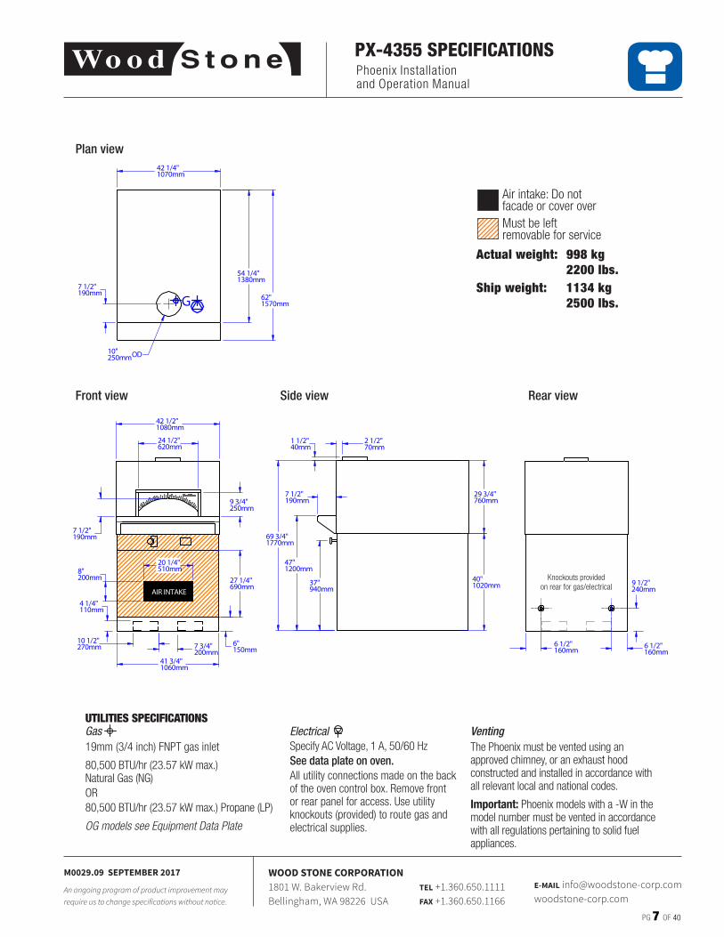
PX-4355 SPECIFICATIONS
UTILITIES SPECIFICATIONSGas 19mm (3/4 inch) FNPT gas inlet
80,500 BTU/hr (23�57 kW max�) Natural Gas (NG)OR80,500 BTU/hr (23�57 kW max�) Propane (LP)
OG models see Equipment Data Plate
Actual weight: 998 kg 2200 lbs.Ship weight: 1134 kg 2500 lbs.
Plan view
Side view Rear viewFront view
Knockouts provided on rear for gas/electrical
Air intake: Do not facade or cover overMust be leftremovable for service
REV:
LEGEND:
PART #: WS-BL-4355
Bistro Commercial Series - 4355General Arrangement
9/18/2013 bena 1DWN BY:SHEET:
Bellingham, WA 360/650-1111 www.woodstone-corp.com
DIMENSIONS ARE IN INCHESTOLERANCES: LINEAR ±1/2 [±10mm], ANGULAR ±2°
UNLESS NOTED OTHERWISE
\\woodstone.net\dfs\CAD\0 Pn\WS Top Level\WS-BL-4355_General_Arrangement-1.dft
THE INFORMATION CONTAINED IN THIS DRAWING IS THESOLE PROPERTY OF WOOD STONE CORPORATION
ANY REPRODUCTION OR USE IN PART OR AS A WHOLEWITHOUT THE WRITTEN PERMISSION OF WOOD STONE IS
PROHIBITED
AN ONGOING PROGRAM OF PRODUCT IMPROVEMENTMAY REQUIRE US TO CHANGE SPECIFICATIONS
WITHOUT NOTICE.
DATE:
G
120VAC, 4A
GAS INLET: 3/4" NPT80,500 BTU, NG68,000 BTU, LP
1 of 1
AIR INTAKE
G
54 1/4"1380mm
24 1/2"620mm
6"150mm
6 1/2"160mm
6 1/2"160mm
1 1/2"40mm
69 3/4"1770mm
7 1/2"190mm
47"1200mm
37"940mm
7 1/2"190mm
29 3/4"760mm
2 1/2"70mm
42 1/2"1080mm
41 3/4"1060mm
62"1570mm
7 1/2"190mm
9 3/4"250mm
10"250mmOD
4 1/4"110mm
7 3/4"200mm
10 1/2"270mm
27 1/4"690mm
40"1020mm
9 1/2"240mm
8"200mm
20 1/4"510mm
42 1/4"1070mm
VentingThe Phoenix must be vented using an approved chimney, or an exhaust hood constructed and installed in accordance with all relevant local and national codes�
Important: Phoenix models with a -W in the model number must be vented in accordance with all regulations pertaining to solid fuel appliances�
ElectricalSpecify AC Voltage, 1 A, 50/60 HzSee data plate on oven.All utility connections made on the back of the oven control box� Remove front or rear panel for access� Use utility knockouts (provided) to route gas and electrical supplies�
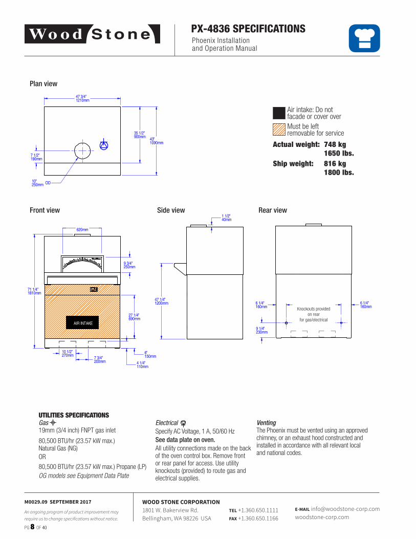
Plan view
Side view Rear viewFront view
Knockouts provided on rear
for gas/electrical
Air intake: Do not facade or cover overMust be leftremovable for service
Phoenix Installation and Operation Manual
PG 8 OF 40
M0029.09 SEPTEMBER 2017
An ongoing program of product improvement may require us to change specifications without notice.
WOOD STONE CORPORATION1801 W. Bakerview Rd.Bellingham, WA 98226 USA
TEL +1.360.650.1111FAX +1.360.650.1166
E-MAIL [email protected]
PX-4836 SPECIFICATIONS
Actual weight: 748 kg 1650 lbs.Ship weight: 816 kg 1800 lbs.
UTILITIES SPECIFICATIONSGas 19mm (3/4 inch) FNPT gas inlet
80,500 BTU/hr (23�57 kW max�) Natural Gas (NG)OR
80,500 BTU/hr (23�57 kW max�) Propane (LP)OG models see Equipment Data Plate
VentingThe Phoenix must be vented using an approved chimney, or an exhaust hood constructed and installed in accordance with all relevant local and national codes�
ElectricalSpecify AC Voltage, 1 A, 50/60 HzSee data plate on oven.All utility connections made on the back of the oven control box� Remove front or rear panel for access� Use utility knockouts (provided) to route gas and electrical supplies�
REV:
LEGEND:
PART #: 001-504836
4836 Bistro - Wood BurningGeneral Arrangement
10/4/2013 bena ADWN BY:SHEET:
Bellingham, WA 360/650-1111 www.woodstone-corp.com
DIMENSIONS ARE IN INCHESTOLERANCES: LINEAR ±1/2 [±10mm], ANGULAR ±2°
UNLESS NOTED OTHERWISE
\\woodstone.net\dfs\CAD\0 Pn\WS Top Level\WS-BL-4836-W_General_Arrangement-0.dft
THE INFORMATION CONTAINED IN THIS DRAWING IS THESOLE PROPERTY OF WOOD STONE CORPORATION
ANY REPRODUCTION OR USE IN PART OR AS A WHOLEWITHOUT THE WRITTEN PERMISSION OF WOOD STONE IS
PROHIBITED
AN ONGOING PROGRAM OF PRODUCT IMPROVEMENTMAY REQUIRE US TO CHANGE SPECIFICATIONS
WITHOUT NOTICE.
DATE:
120VAC, 2A
1 of 1
AIR INTAKE
43"1090mm
7 1/2"190mm
10"250mm OD
71 1/4"1810mm
9 3/4"250mm
24 1/2"620mm
6"150mm
47 1/4"1200mm
47 3/4"1210mm
1 1/2"40mm
9 1/4"230mm
6 1/4"160mm
6 1/4"160mm
35 1/2"900mm
10 1/2"270mm
7 3/4"200mm 4 1/4"
110mm
27 1/4"690mm
Phoenix Installation and Operation Manual
PG 9 OF 40
M0029.09 SEPTEMBER 2017
An ongoing program of product improvement may require us to change specifications without notice.
WOOD STONE CORPORATION1801 W. Bakerview Rd.Bellingham, WA 98226 USA
TEL +1.360.650.1111FAX +1.360.650.1166
E-MAIL [email protected]
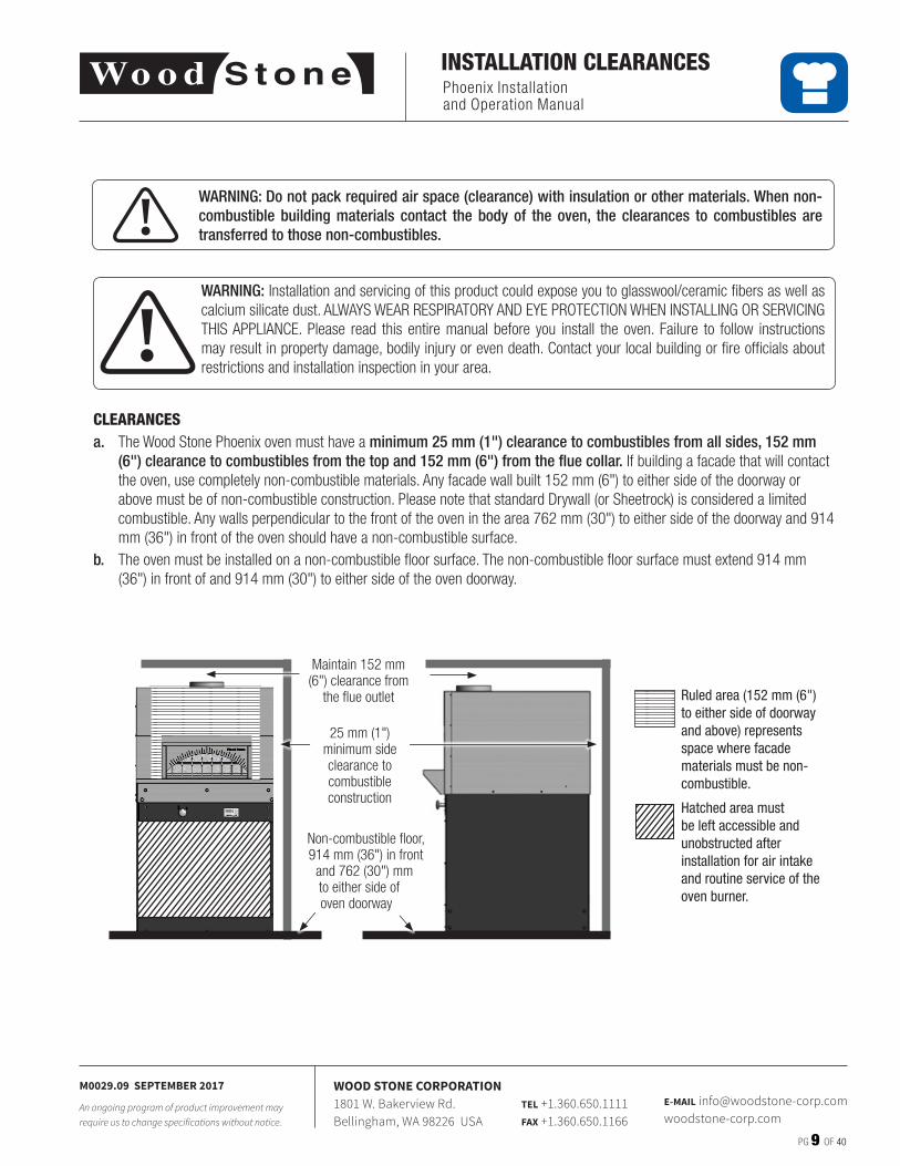
INSTALLATION CLEARANCES
CLEARANCES a. The Wood Stone Phoenix oven must have a minimum 25 mm (1") clearance to combustibles from all sides, 152 mm
(6") clearance to combustibles from the top and 152 mm (6") from the flue collar. If building a facade that will contact the oven, use completely non-combustible materials� Any facade wall built 152 mm (6") to either side of the doorway or above must be of non-combustible construction� Please note that standard Drywall (or Sheetrock) is considered a limited combustible� Any walls perpendicular to the front of the oven in the area 762 mm (30") to either side of the doorway and 914 mm (36") in front of the oven should have a non-combustible surface�
b. The oven must be installed on a non-combustible floor surface� The non-combustible floor surface must extend 914 mm (36") in front of and 914 mm (30") to either side of the oven doorway�
!WARNING: Installation and servicing of this product could expose you to glasswool/ceramic fibers as well as calcium silicate dust� ALWAYS WEAR RESPIRATORY AND EYE PROTECTION WHEN INSTALLING OR SERVICING THIS APPLIANCE� Please read this entire manual before you install the oven� Failure to follow instructions may result in property damage, bodily injury or even death� Contact your local building or fire officials about restrictions and installation inspection in your area�
! WARNING: Do not pack required air space (clearance) with insulation or other materials. When non-combustible building materials contact the body of the oven, the clearances to combustibles are transferred to those non-combustibles.
Maintain 152 mm (6") clearance from
the flue outlet Ruled area (152 mm (6") to either side of doorway and above) represents space where facade materials must be non-combustible.
Hatched area must be left accessible and unobstructed after installation for air intake and routine service of the oven burner.
25 mm (1") minimum side clearance to combustible construction
Non-combustible floor, 914 mm (36") in front
and 762 (30") mm to either side of oven doorway
Phoenix Installation and Operation Manual
PG 10 OF 40 M0029.09 SEPTEMBER 2017
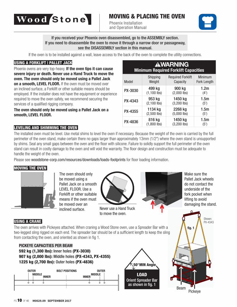
MOVING & PLACING THE OVEN
Minimum Required Forklift Capacities
ModelShipping Weight
Required Forklift Capacity
Minimum Fork Length
PX-3030 499 kg(1,100 lbs)
900 kg(2,000 lbs)
1.2m (4')
PX-4343 953 kg(2,100 lbs)
1450 kg(3,200 lbs)
1.5m (5')
PX-4355 1134 kg(2,500 lbs)
2268 kg(5,000 lbs)
1.5m (5')
PX-4836 816 kg(1,800 lbs)
1450 kg(3,200 lbs)
1.5m (5')
WARNING
The oven should only be moved using a Pallet Jack on a smooth LEVEL FLOOR. Use a Forklift or other suitable means if the oven must be moved over an inclined surface.
Ü Ü
Make sure the Pallet Jack wheels do not contact the underside of the fork pocket when lifting to avoid damaging the stand.
PICKEYE CAPACITIES PER BEAM592 kg (1,300 lbs): Inner holes (PX-3030)907 kg (2,000 lbs): Middle holes (PX-4343, PX-4355)1225 kg (2,700 lbs): Outer holes (PX-4836)
INNER INNERMIDDLE MIDDLE
OUTER OUTERBOLT POSITIONS
Never use a Hand Truck to move the oven.
LOADOrient Spreader Baras shown in fig. 1
50°MIN Angle
PickeyeBeam
Shown: PX-4343
fig. 1
If you received your Phoenix oven disassembled, go to the ASSEMBLY section.If you need to disassemble the oven to move it through a narrow door or passageway,
see the DISASSEMBLY section in this manual.
If the oven is to be installed against a wall, leave access to the back of the oven to complete the utility connections�
USING A CRANE.The oven arrives with Pickeyes attached� When craning a Wood Stone oven, use a Spreader Bar with a two-legged sling rigged on each end� The spreader bar should be of a sufficient length to keep the sling from contacting the oven, and oriented as shown in fig 1�
LEVELING AND SHIMMING THE OVEN.The installed oven must be level� Use metal shims to level the oven if necessary� Because the weight of the oven is carried by the full perimeter of the oven stand, make certain there no gaps larger than approximately 13mm (1/2") where the oven stand is unsupported by shims� Seal any small gaps between the oven and the floor with silicone� Failure to solidly support the full perimeter of the oven stand can result in costly damage to the oven and will void the warranty� The floor design and construction must be adequate to handle the weight of the oven� Please see woodstone-corp.com/resources/downloads/loads-footprints for floor loading information�
MOVING THE OVEN.
USING A FORKLIFT | PALLET JACKPhoenix ovens are very top-heavy� If the oven tips it can cause severe injury or death. Never use a Hand Truck to move the oven. The oven should only be moved using a Pallet Jack on a smooth, LEVEL FLOOR. If the oven must be moved over an inclined surface, a Forklift or other suitable means should be employed� If the installer does not have the equipment or experience required to move the oven safely, we recommend securing the services of a qualified rigging company�The oven should only be moved using a Pallet Jack on a smooth, LEVEL FLOOR.
Phoenix Installation and Operation Manual
PG 11 OF 40
M0029.09 SEPTEMBER 2017
An ongoing program of product improvement may require us to change specifications without notice.
WOOD STONE CORPORATION1801 W. Bakerview Rd.Bellingham, WA 98226 USA
TEL +1.360.650.1111FAX +1.360.650.1166
E-MAIL [email protected]
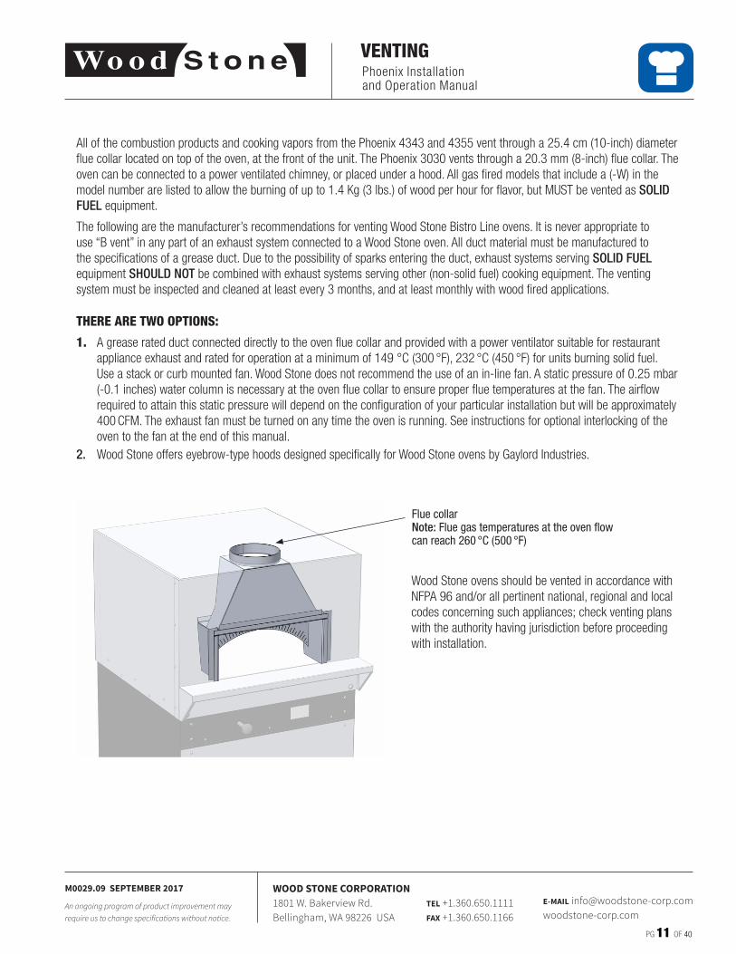
VENTING
Wood Stone ovens should be vented in accordance with NFPA 96 and/or all pertinent national, regional and local codes concerning such appliances; check venting plans with the authority having jurisdiction before proceeding with installation�
All of the combustion products and cooking vapors from the Phoenix 4343 and 4355 vent through a 25�4 cm (10-inch) diameter flue collar located on top of the oven, at the front of the unit� The Phoenix 3030 vents through a 20�3 mm (8-inch) flue collar� The oven can be connected to a power ventilated chimney, or placed under a hood� All gas fired models that include a (-W) in the model number are listed to allow the burning of up to 1�4 Kg (3 lbs�) of wood per hour for flavor, but MUST be vented as SOLID FUEL equipment�
The following are the manufacturer’s recommendations for venting Wood Stone Bistro Line ovens� It is never appropriate to use “B vent” in any part of an exhaust system connected to a Wood Stone oven� All duct material must be manufactured to the specifications of a grease duct� Due to the possibility of sparks entering the duct, exhaust systems serving SOLID FUEL equipment SHOULD NOT be combined with exhaust systems serving other (non-solid fuel) cooking equipment� The venting system must be inspected and cleaned at least every 3 months, and at least monthly with wood fired applications�
THERE ARE TWO OPTIONS:
1. A grease rated duct connected directly to the oven flue collar and provided with a power ventilator suitable for restaurant appliance exhaust and rated for operation at a minimum of 149 °C (300 °F), 232 °C (450 °F) for units burning solid fuel� Use a stack or curb mounted fan� Wood Stone does not recommend the use of an in-line fan� A static pressure of 0�25 mbar (-0�1 inches) water column is necessary at the oven flue collar to ensure proper flue temperatures at the fan� The airflow required to attain this static pressure will depend on the configuration of your particular installation but will be approximately 400 CFM� The exhaust fan must be turned on any time the oven is running� See instructions for optional interlocking of the oven to the fan at the end of this manual�
2. Wood Stone offers eyebrow-type hoods designed specifically for Wood Stone ovens by Gaylord Industries�
Flue collarNote: Flue gas temperatures at the oven flow can reach 260 °C (500 °F)
Phoenix Installation and Operation Manual
PG 12 OF 40
M0029.09 SEPTEMBER 2017
An ongoing program of product improvement may require us to change specifications without notice.
WOOD STONE CORPORATION1801 W. Bakerview Rd.Bellingham, WA 98226 USA
TEL +1.360.650.1111FAX +1.360.650.1166
E-MAIL [email protected]
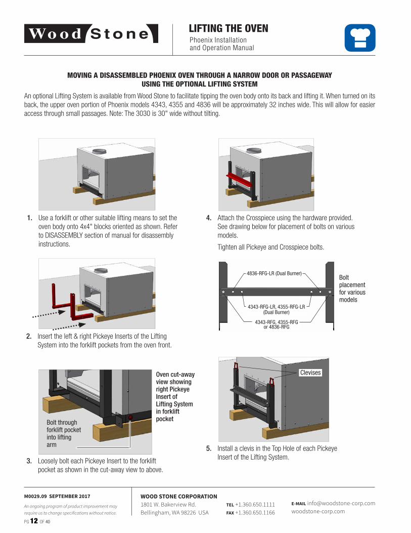
LIFTING THE OVEN
1. Use a forklift or other suitable lifting means to set the oven body onto 4x4" blocks oriented as shown� Refer to DISASSEMBLY section of manual for disassembly instructions�
Oven cut-away view showing right Pickeye Insert of Lifting System in forklift pocketBolt through
forklift pocket into lifting arm
2. Insert the left & right Pickeye Inserts of the Lifting System into the forklift pockets from the oven front�
3. Loosely bolt each Pickeye Insert to the forklift pocket as shown in the cut-away view to above�
MOVING A DISASSEMBLED PHOENIX OVEN THROUGH A NARROW DOOR OR PASSAGEWAY USING THE OPTIONAL LIFTING SYSTEM
An optional Lifting System is available from Wood Stone to facilitate tipping the oven body onto its back and lifting it� When turned on its back, the upper oven portion of Phoenix models 4343, 4355 and 4836 will be approximately 32 inches wide� This will allow for easier access through small passages� Note: The 3030 is 30" wide without tilting�
4. Attach the Crosspiece using the hardware provided� See drawing below for placement of bolts on various models�
Tighten all Pickeye and Crosspiece bolts�
Bolt placement for various models
4343-RFG, 4355-RFG or 4836-RFG
4343-RFG-LR, 4355-RFG-LR (Dual Burner)
4836-RFG-LR (Dual Burner)
Clevises
5. Install a clevis in the Top Hole of each Pickeye Insert of the Lifting System�
Phoenix Installation and Operation Manual
PG 13 OF 40M0029.09 SEPTEMBER 2017
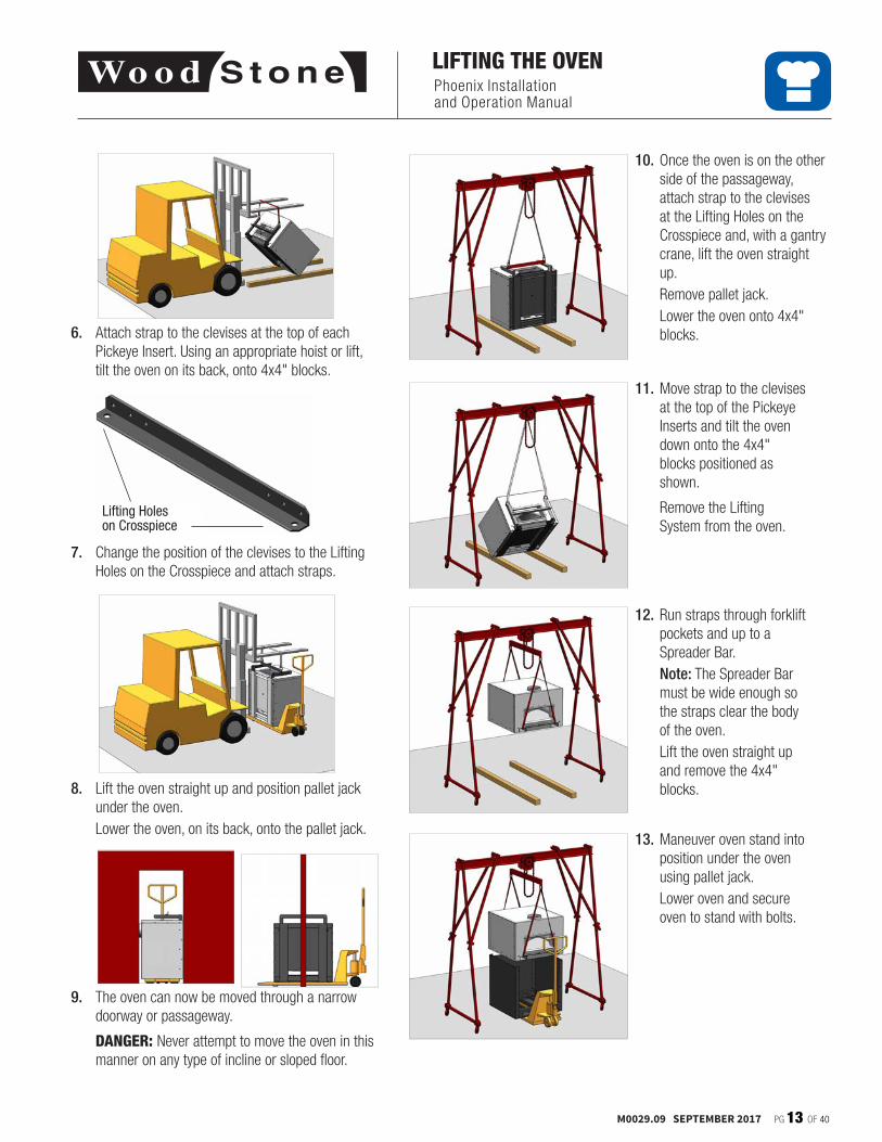
LIFTING THE OVEN
6. Attach strap to the clevises at the top of each Pickeye Insert� Using an appropriate hoist or lift, tilt the oven on its back, onto 4x4" blocks�
7. Change the position of the clevises to the Lifting Holes on the Crosspiece and attach straps�
Lifting Holes on Crosspiece
8. Lift the oven straight up and position pallet jack under the oven�
Lower the oven, on its back, onto the pallet jack�
9. The oven can now be moved through a narrow doorway or passageway�
DANGER: Never attempt to move the oven in this manner on any type of incline or sloped floor�
10. Once the oven is on the other side of the passageway, attach strap to the clevises at the Lifting Holes on the Crosspiece and, with a gantry crane, lift the oven straight up�
Remove pallet jack� Lower the oven onto 4x4"
blocks�
11. Move strap to the clevises at the top of the Pickeye Inserts and tilt the oven down onto the 4x4" blocks positioned as shown�
Remove the Lifting System from the oven�
12. Run straps through forklift pockets and up to a Spreader Bar�
Note: The Spreader Bar must be wide enough so the straps clear the body of the oven�
Lift the oven straight up and remove the 4x4" blocks�
13. Maneuver oven stand into position under the oven using pallet jack�
Lower oven and secure oven to stand with bolts�
Phoenix Installation and Operation Manual
PG 14 OF 40
M0029.09 SEPTEMBER 2017
An ongoing program of product improvement may require us to change specifications without notice.
WOOD STONE CORPORATION1801 W. Bakerview Rd.Bellingham, WA 98226 USA
TEL +1.360.650.1111FAX +1.360.650.1166
E-MAIL [email protected]
EXPLODED PARTS DIAGRAM
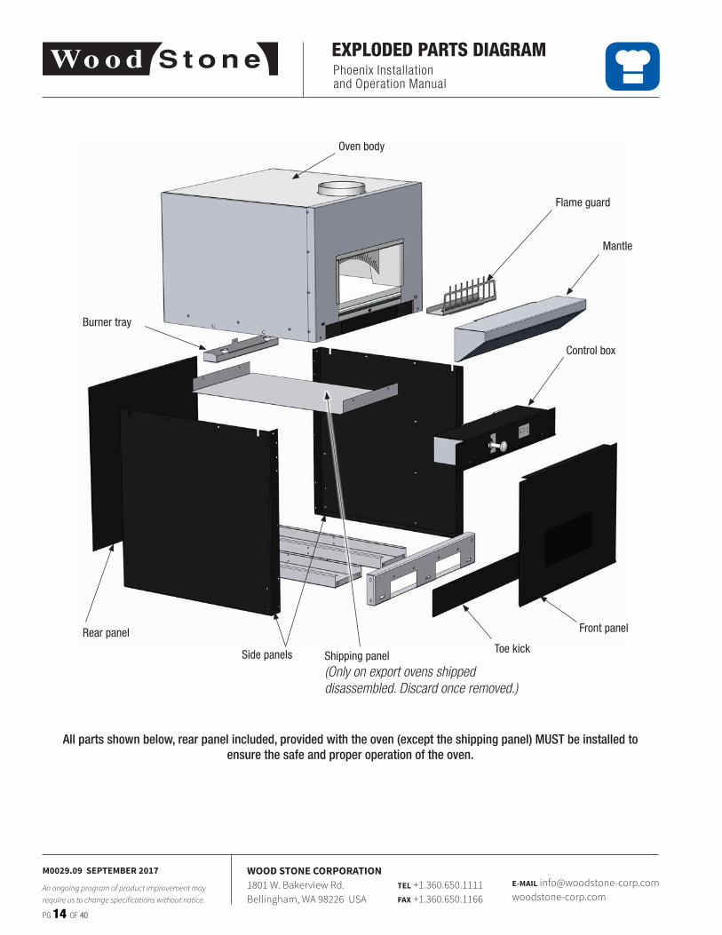
All parts shown below, rear panel included, provided with the oven (except the shipping panel) MUST be installed to ensure the safe and proper operation of the oven.
Oven body
Control box
Flame guard
Burner tray
Front panel
Toe kickRear panel
Shipping panel(Only on export ovens shipped disassembled. Discard once removed.)
Side panels
Mantle
Phoenix Installation and Operation Manual
PG 15 OF 40
M0029.09 SEPTEMBER 2017
An ongoing program of product improvement may require us to change specifications without notice.
WOOD STONE CORPORATION1801 W. Bakerview Rd.Bellingham, WA 98226 USA
TEL +1.360.650.1111FAX +1.360.650.1166
E-MAIL [email protected]
ASSEMBLY
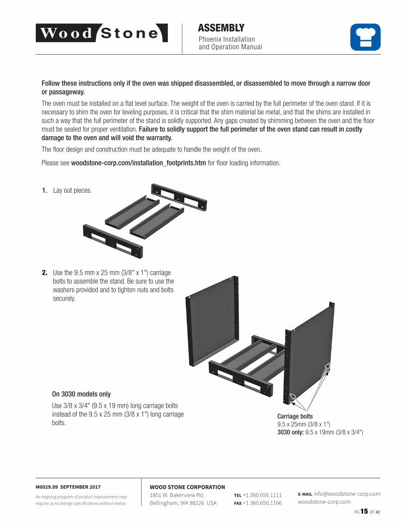
Follow these instructions only if the oven was shipped disassembled, or disassembled to move through a narrow door or passageway.
The oven must be installed on a flat level surface� The weight of the oven is carried by the full perimeter of the oven stand� If it is necessary to shim the oven for leveling purposes, it is critical that the shim material be metal, and that the shims are installed in such a way that the full perimeter of the stand is solidly supported� Any gaps created by shimming between the oven and the floor must be sealed for proper ventilation� Failure to solidly support the full perimeter of the oven stand can result in costly damage to the oven and will void the warranty.
The floor design and construction must be adequate to handle the weight of the oven�
Please see woodstone-corp.com/installation_footprints.htm for floor loading information�
2. Use the 9�5 mm x 25 mm (3/8" x 1") carriage bolts to assemble the stand� Be sure to use the washers provided and to tighten nuts and bolts securely�
1. Lay out pieces�
Carriage bolts9�5 x 25mm (3/8 x 1")3030 only: 9�5 x 19mm (3/8 x 3/4")
On 3030 models only
Use 3/8 x 3/4" (9�5 x 19 mm) long carriage bolts instead of the 9�5 x 25 mm (3/8 x 1") long carriage bolts�
Phoenix Installation and Operation Manual
PG 16 OF 40
M0029.09 SEPTEMBER 2017
An ongoing program of product improvement may require us to change specifications without notice.
WOOD STONE CORPORATION1801 W. Bakerview Rd.Bellingham, WA 98226 USA
TEL +1.360.650.1111FAX +1.360.650.1166
E-MAIL [email protected]
ASSEMBLY
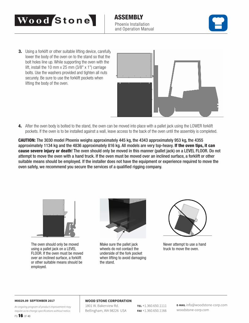
3. Using a forklift or other suitable lifting device, carefully lower the body of the oven on to the stand so that the bolt holes line up� While supporting the oven with the lift, install the 10 mm x 25 mm (3/8" x 1") carriage bolts� Use the washers provided and tighten all nuts securely� Be sure to use the forklift pockets when lifting the body of the oven�
4. After the oven body is bolted to the stand, the oven can be moved into place with a pallet jack using the LOWER forklift pockets� If the oven is to be installed against a wall, leave access to the back of the oven until the assembly is completed�
CAUTION: The 3030 model Phoenix weighs approximately 445 kg, the 4343 approximately 953 kg, the 4355 approximately 1134 kg and the 4836 approximately 816 kg. All models are very top-heavy. If the oven tips, it can cause severe injury or death! The oven should only be moved in this manner (pallet jack) on a LEVEL FLOOR. Do not attempt to move the oven with a hand truck. If the oven must be moved over an inclined surface, a forklift or other suitable means should be employed. If the installer does not have the equipment or experience required to move the oven safely, we recommend you secure the services of a qualified rigging company.
Make sure the pallet jack wheels do not contact the underside of the fork pocket when lifting to avoid damaging the stand.
Never attempt to use a hand truck to move the oven.
The oven should only be moved using a pallet jack on a LEVEL FLOOR. If the oven must be moved over an inclined surface, a forklift or other suitable means should be employed.
Phoenix Installation and Operation Manual
PG 17 OF 40
M0029.09 SEPTEMBER 2017
An ongoing program of product improvement may require us to change specifications without notice.
WOOD STONE CORPORATION1801 W. Bakerview Rd.Bellingham, WA 98226 USA
TEL +1.360.650.1111FAX +1.360.650.1166
E-MAIL [email protected]
ASSEMBLY
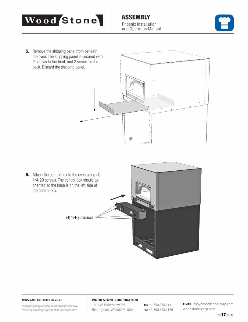
5. Remove the shipping panel from beneath the oven� The shipping panel is secured with 2 screws in the front, and 2 screws in the back� Discard the shipping panel�
6. Attach the control box to the oven using (4) 1/4-20 screws� The control box should be oriented so the knob is on the left side of the control box�
(4) 1/4-20 screws
Phoenix Installation and Operation Manual
PG 18 OF 40
M0029.09 SEPTEMBER 2017
An ongoing program of product improvement may require us to change specifications without notice.
WOOD STONE CORPORATION1801 W. Bakerview Rd.Bellingham, WA 98226 USA
TEL +1.360.650.1111FAX +1.360.650.1166
E-MAIL [email protected]
ASSEMBLY
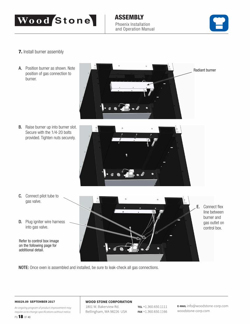
7. Install burner assembly
Radiant burnerA. Position burner as shown� Note position of gas connection to burner�
B. Raise burner up into burner slot� Secure with the 1/4-20 bolts provided� Tighten nuts securely�
C. Connect pilot tube to gas valve�
E. Connect flex line between burner and gas outlet on control box�
D. Plug igniter wire harness into gas valve�
NOTE: Once oven is assembled and installed, be sure to leak-check all gas connections�
Refer to control box image on the following page for additional detail.
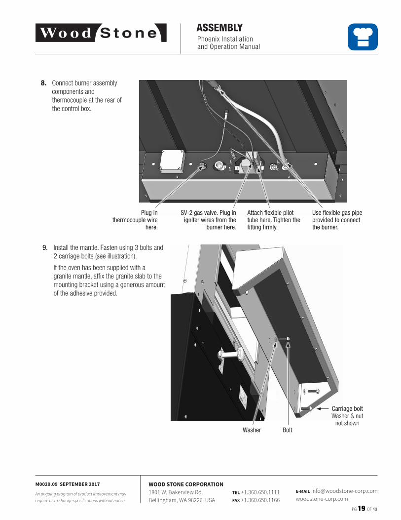
9. Install the mantle� Fasten using 3 bolts and 2 carriage bolts (see illustration)�
If the oven has been supplied with a granite mantle, affix the granite slab to the mounting bracket using a generous amount of the adhesive provided�
Carriage boltWasher & nut
not shownWasher Bolt
Phoenix Installation and Operation Manual
PG 19 OF 40
M0029.09 SEPTEMBER 2017
An ongoing program of product improvement may require us to change specifications without notice.
WOOD STONE CORPORATION1801 W. Bakerview Rd.Bellingham, WA 98226 USA
TEL +1.360.650.1111FAX +1.360.650.1166
E-MAIL [email protected]
ASSEMBLY
8. Connect burner assembly components and thermocouple at the rear of the control box�
Plug in thermocouple wire
here.
SV-2 gas valve. Plug in igniter wires from the
burner here.
Attach flexible pilot tube here. Tighten the fitting firmly.
Use flexible gas pipe provided to connect the burner.
Phoenix Installation and Operation Manual
PG 20 OF 40
M0029.09 SEPTEMBER 2017
An ongoing program of product improvement may require us to change specifications without notice.
WOOD STONE CORPORATION1801 W. Bakerview Rd.Bellingham, WA 98226 USA
TEL +1.360.650.1111FAX +1.360.650.1166
E-MAIL [email protected]
ASSEMBLY
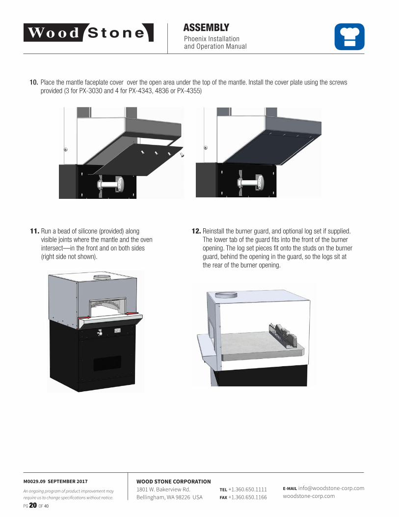
11. Run a bead of silicone (provided) along visible joints where the mantle and the oven intersect—in the front and on both sides (right side not shown)�
12. Reinstall the burner guard, and optional log set if supplied� The lower tab of the guard fits into the front of the burner opening� The log set pieces fit onto the studs on the burner guard, behind the opening in the guard, so the logs sit at the rear of the burner opening�
10. Place the mantle faceplate cover over the open area under the top of the mantle� Install the cover plate using the screws provided (3 for PX-3030 and 4 for PX-4343, 4836 or PX-4355)
Phoenix Installation and Operation Manual
PG 21 OF 40
M0029.09 SEPTEMBER 2017
An ongoing program of product improvement may require us to change specifications without notice.
WOOD STONE CORPORATION1801 W. Bakerview Rd.Bellingham, WA 98226 USA
TEL +1.360.650.1111FAX +1.360.650.1166
E-MAIL [email protected]
UTILITY CONNECTIONS
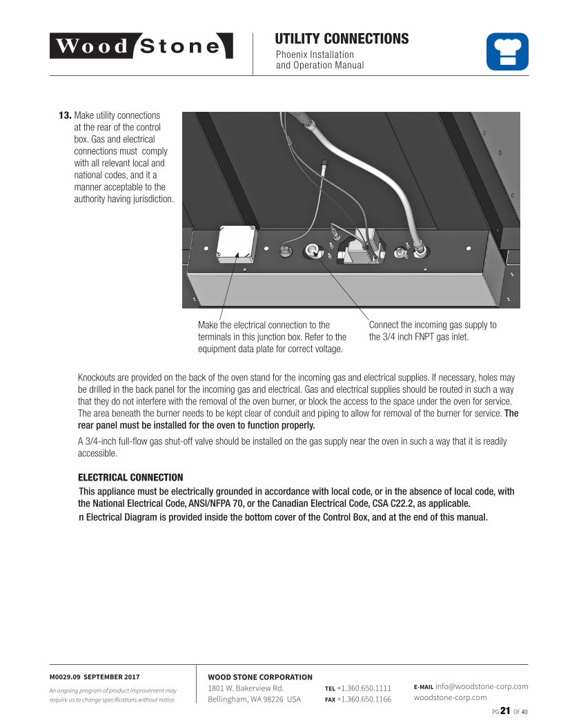
Make the electrical connection to the terminals in this junction box� Refer to the equipment data plate for correct voltage�
Connect the incoming gas supply to the 3/4 inch FNPT gas inlet�
Knockouts are provided on the back of the oven stand for the incoming gas and electrical supplies� If necessary, holes may be drilled in the back panel for the incoming gas and electrical� Gas and electrical supplies should be routed in such a way that they do not interfere with the removal of the oven burner, or block the access to the space under the oven for service� The area beneath the burner needs to be kept clear of conduit and piping to allow for removal of the burner for service� The rear panel must be installed for the oven to function properly.
A 3/4-inch full-flow gas shut-off valve should be installed on the gas supply near the oven in such a way that it is readily accessible�
ELECTRICAL CONNECTIONThis appliance must be electrically grounded in accordance with local code, or in the absence of local code, with the National Electrical Code, ANSI/NFPA 70, or the Canadian Electrical Code, CSA C22.2, as applicable.n Electrical Diagram is provided inside the bottom cover of the Control Box, and at the end of this manual.
13. Make utility connections at the rear of the control box� Gas and electrical connections must comply with all relevant local and national codes, and it a manner acceptable to the authority having jurisdiction�
Phoenix Installation and Operation Manual
PG 22 OF 40
M0029.09 SEPTEMBER 2017
An ongoing program of product improvement may require us to change specifications without notice.
WOOD STONE CORPORATION1801 W. Bakerview Rd.Bellingham, WA 98226 USA
TEL +1.360.650.1111FAX +1.360.650.1166
E-MAIL [email protected]
UTILITY CONNECTIONS
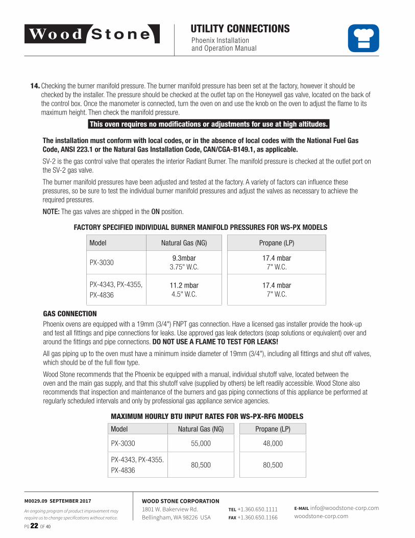
Model Natural Gas (NG) Propane (LP)
PX-30309.3mbar
3�75" W�C�17.4 mbar
7" W�C�
PX-4343, PX-4355,PX-4836
11.2 mbar4�5" W�C�
17.4 mbar7" W�C�
14. Checking the burner manifold pressure� The burner manifold pressure has been set at the factory, however it should be checked by the installer� The pressure should be checked at the outlet tap on the Honeywell gas valve, located on the back of the control box� Once the manometer is connected, turn the oven on and use the knob on the oven to adjust the flame to its maximum height� Then check the manifold pressure�
This oven requires no modifications or adjustments for use at high altitudes.
The installation must conform with local codes, or in the absence of local codes with the National Fuel Gas Code, ANSI 223.1 or the Natural Gas Installation Code, CAN/CGA-B149.1, as applicable.
SV-2 is the gas control valve that operates the interior Radiant Burner� The manifold pressure is checked at the outlet port on the SV-2 gas valve�
The burner manifold pressures have been adjusted and tested at the factory� A variety of factors can influence these pressures, so be sure to test the individual burner manifold pressures and adjust the valves as necessary to achieve the required pressures�
NOTE: The gas valves are shipped in the ON position�
GAS CONNECTIONPhoenix ovens are equipped with a 19mm (3/4") FNPT gas connection� Have a licensed gas installer provide the hook-up and test all fittings and pipe connections for leaks� Use approved gas leak detectors (soap solutions or equivalent) over and around the fittings and pipe connections� DO NOT USE A FLAME TO TEST FOR LEAKS!
All gas piping up to the oven must have a minimum inside diameter of 19mm (3/4"), including all fittings and shut off valves, which should be of the full flow type�
Wood Stone recommends that the Phoenix be equipped with a manual, individual shutoff valve, located between the oven and the main gas supply, and that this shutoff valve (supplied by others) be left readily accessible� Wood Stone also recommends that inspection and maintenance of the burners and gas piping connections of this appliance be performed at regularly scheduled intervals and only by professional gas appliance service agencies�
MAXIMUM HOURLY BTU INPUT RATES FOR WS-PX-RFG MODELS
Model Natural Gas (NG) Propane (LP)
PX-3030 55,000 48,000
PX-4343, PX-4355�PX-4836
80,500 80,500
FACTORY SPECIFIED INDIVIDUAL BURNER MANIFOLD PRESSURES FOR WS-PX MODELS
Phoenix Installation and Operation Manual
PG 23 OF 40
M0029.09 SEPTEMBER 2017
An ongoing program of product improvement may require us to change specifications without notice.
WOOD STONE CORPORATION1801 W. Bakerview Rd.Bellingham, WA 98226 USA
TEL +1.360.650.1111FAX +1.360.650.1166
E-MAIL [email protected]
UTILITY CONNECTIONS
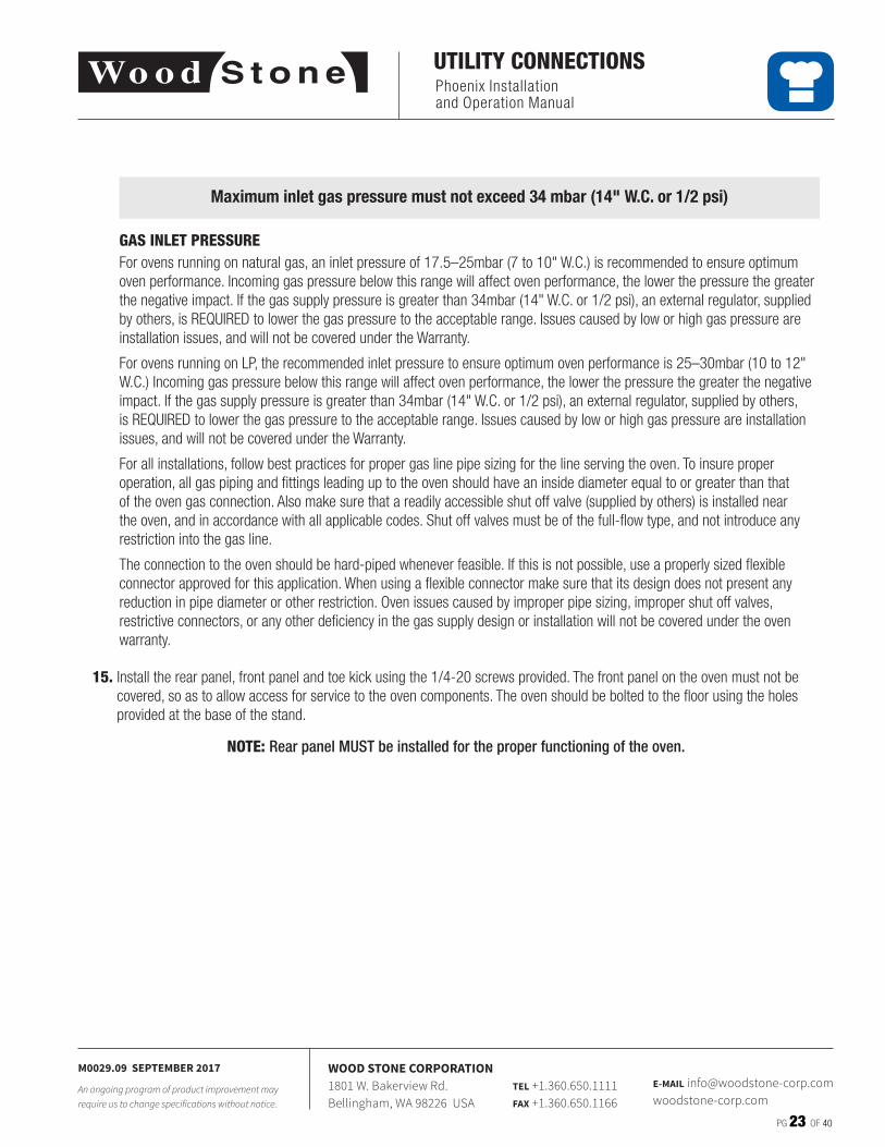
Maximum inlet gas pressure must not exceed 34 mbar (14" W.C. or 1/2 psi)
GAS INLET PRESSUREFor ovens running on natural gas, an inlet pressure of 17�5–25mbar (7 to 10" W�C�) is recommended to ensure optimum oven performance� Incoming gas pressure below this range will affect oven performance, the lower the pressure the greater the negative impact� If the gas supply pressure is greater than 34mbar (14" W�C� or 1/2 psi), an external regulator, supplied by others, is REQUIRED to lower the gas pressure to the acceptable range� Issues caused by low or high gas pressure are installation issues, and will not be covered under the Warranty�
For ovens running on LP, the recommended inlet pressure to ensure optimum oven performance is 25–30mbar (10 to 12" W�C�) Incoming gas pressure below this range will affect oven performance, the lower the pressure the greater the negative impact� If the gas supply pressure is greater than 34mbar (14" W�C� or 1/2 psi), an external regulator, supplied by others, is REQUIRED to lower the gas pressure to the acceptable range� Issues caused by low or high gas pressure are installation issues, and will not be covered under the Warranty�
For all installations, follow best practices for proper gas line pipe sizing for the line serving the oven� To insure proper operation, all gas piping and fittings leading up to the oven should have an inside diameter equal to or greater than that of the oven gas connection� Also make sure that a readily accessible shut off valve (supplied by others) is installed near the oven, and in accordance with all applicable codes� Shut off valves must be of the full-flow type, and not introduce any restriction into the gas line�
The connection to the oven should be hard-piped whenever feasible� If this is not possible, use a properly sized flexible connector approved for this application� When using a flexible connector make sure that its design does not present any reduction in pipe diameter or other restriction� Oven issues caused by improper pipe sizing, improper shut off valves, restrictive connectors, or any other deficiency in the gas supply design or installation will not be covered under the oven warranty�
15. Install the rear panel, front panel and toe kick using the 1/4-20 screws provided� The front panel on the oven must not be covered, so as to allow access for service to the oven components� The oven should be bolted to the floor using the holes provided at the base of the stand�
NOTE: Rear panel MUST be installed for the proper functioning of the oven.
Phoenix Installation and Operation Manual
PG 24 OF 40
M0029.09 SEPTEMBER 2017
An ongoing program of product improvement may require us to change specifications without notice.
WOOD STONE CORPORATION1801 W. Bakerview Rd.Bellingham, WA 98226 USA
TEL +1.360.650.1111FAX +1.360.650.1166
E-MAIL [email protected]
STORAGE BOX INSTALLATION
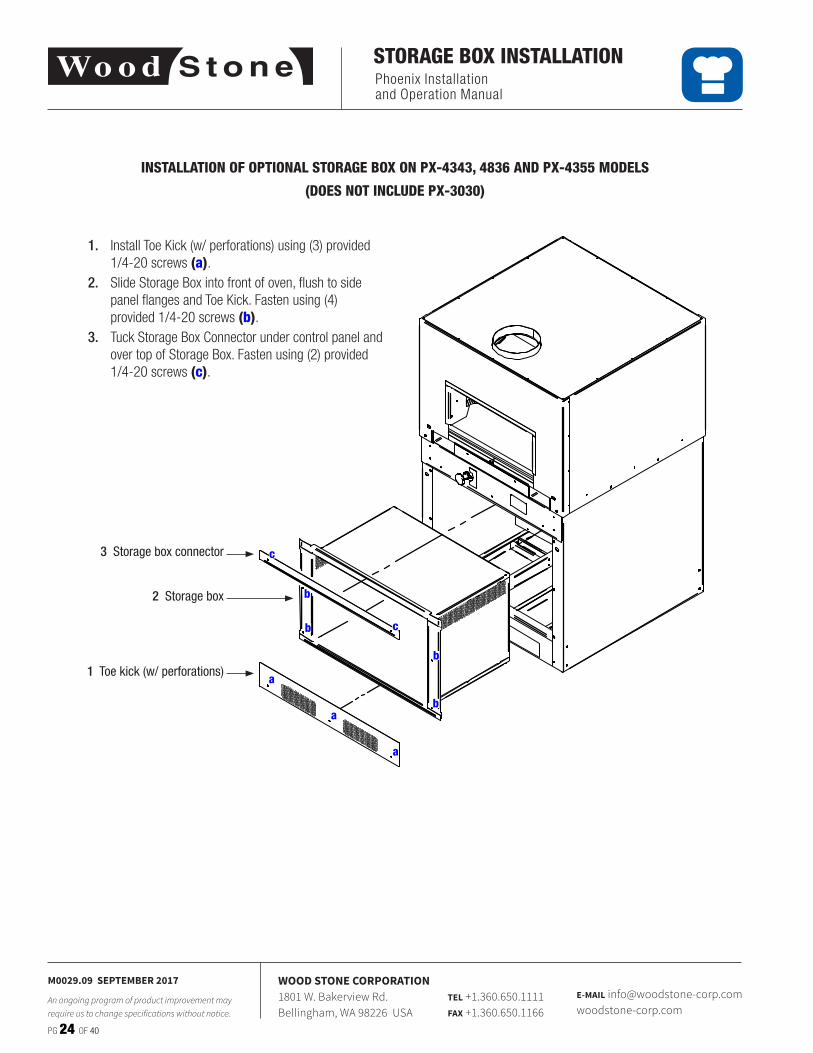
INSTALLATION OF OPTIONAL STORAGE BOX ON PX-4343, 4836 AND PX-4355 MODELS
(DOES NOT INCLUDE PX-3030)
File Location: \\woodstone.net\dfs\CAD\0_Ovens\z_BenA_Prelim\Bistro_Box\WS-BL-4343.dft
REV:
DATE:
PART #: Bistro Commercial Series - 4343
6/11/2013 benaDWN BY:
SHEET:
Bistro Commercial Series - 4343 General Arrangement
01 of 1
Item Part Number Rev Description Material Qty
1 002-434310 6 Storage Box 1
2 1640571 0 Storage Box Connector Stainless Steel, 304 1
3 1640572 0 Toe Kick w/Perf Stainless Steel, 304 1
2 Storage box
1 Toe kick (w/ perforations)
3 Storage box connector
1. Install Toe Kick (w/ perforations) using (3) provided 1/4-20 screws (a)�
2. Slide Storage Box into front of oven, flush to side panel flanges and Toe Kick� Fasten using (4) provided 1/4-20 screws (b)�
3. Tuck Storage Box Connector under control panel and over top of Storage Box� Fasten using (2) provided 1/4-20 screws (c)�
b
a
a
a
b
b
b
c
c
Phoenix Installation and Operation Manual
PG 25 OF 40
M0029.09 SEPTEMBER 2017
An ongoing program of product improvement may require us to change specifications without notice.
WOOD STONE CORPORATION1801 W. Bakerview Rd.Bellingham, WA 98226 USA
TEL +1.360.650.1111FAX +1.360.650.1166
E-MAIL [email protected]
DISASSEMBLY
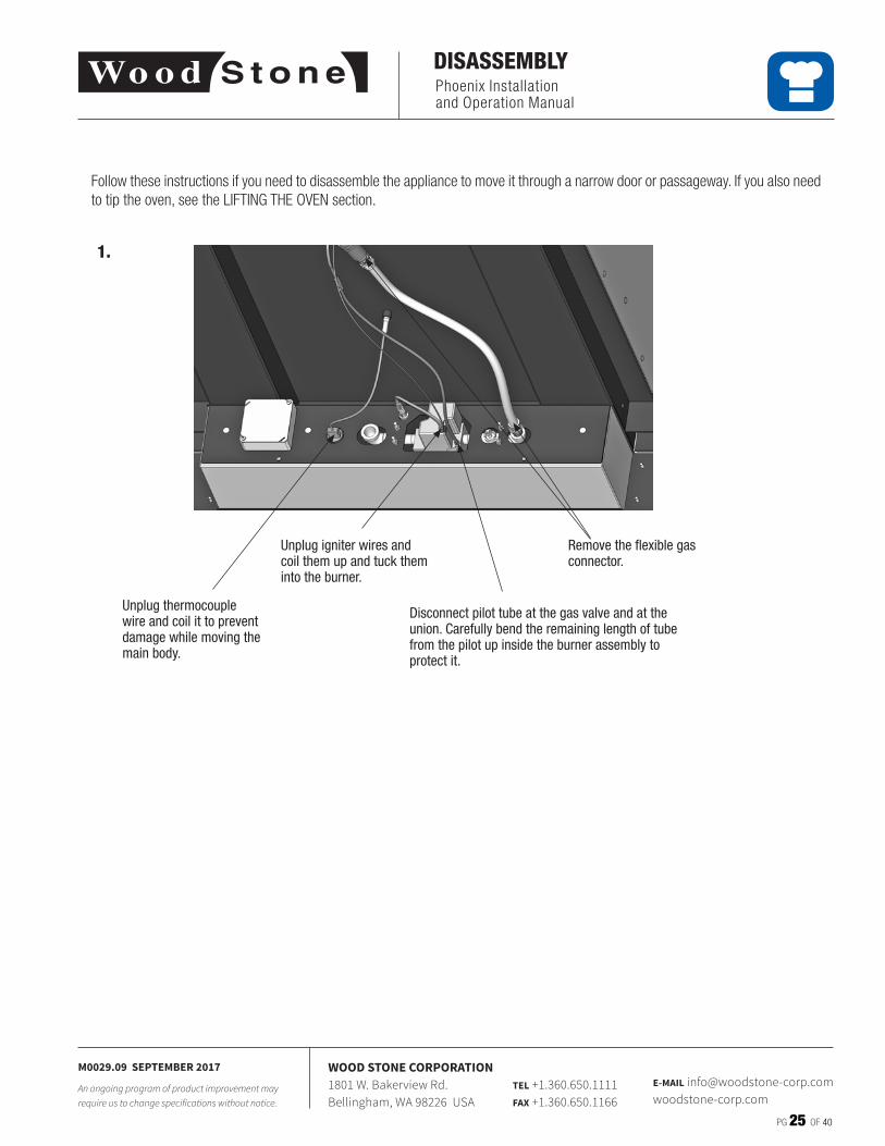
Follow these instructions if you need to disassemble the appliance to move it through a narrow door or passageway� If you also need to tip the oven, see the LIFTING THE OVEN section�
Unplug thermocouple wire and coil it to prevent damage while moving the main body.
Unplug igniter wires and coil them up and tuck them into the burner.
Disconnect pilot tube at the gas valve and at the union. Carefully bend the remaining length of tube from the pilot up inside the burner assembly to protect it.
Remove the flexible gas connector.
1.
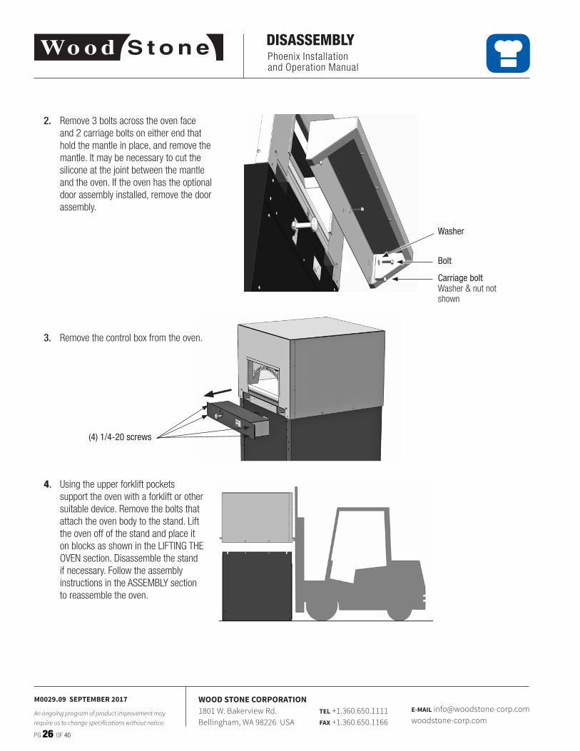
2. Remove 3 bolts across the oven face and 2 carriage bolts on either end that hold the mantle in place, and remove the mantle� It may be necessary to cut the silicone at the joint between the mantle and the oven� If the oven has the optional door assembly installed, remove the door assembly�
Carriage boltWasher & nut not shown
Washer
Bolt
Phoenix Installation and Operation Manual
PG 26 OF 40
M0029.09 SEPTEMBER 2017
An ongoing program of product improvement may require us to change specifications without notice.
WOOD STONE CORPORATION1801 W. Bakerview Rd.Bellingham, WA 98226 USA
TEL +1.360.650.1111FAX +1.360.650.1166
E-MAIL [email protected]
DISASSEMBLY
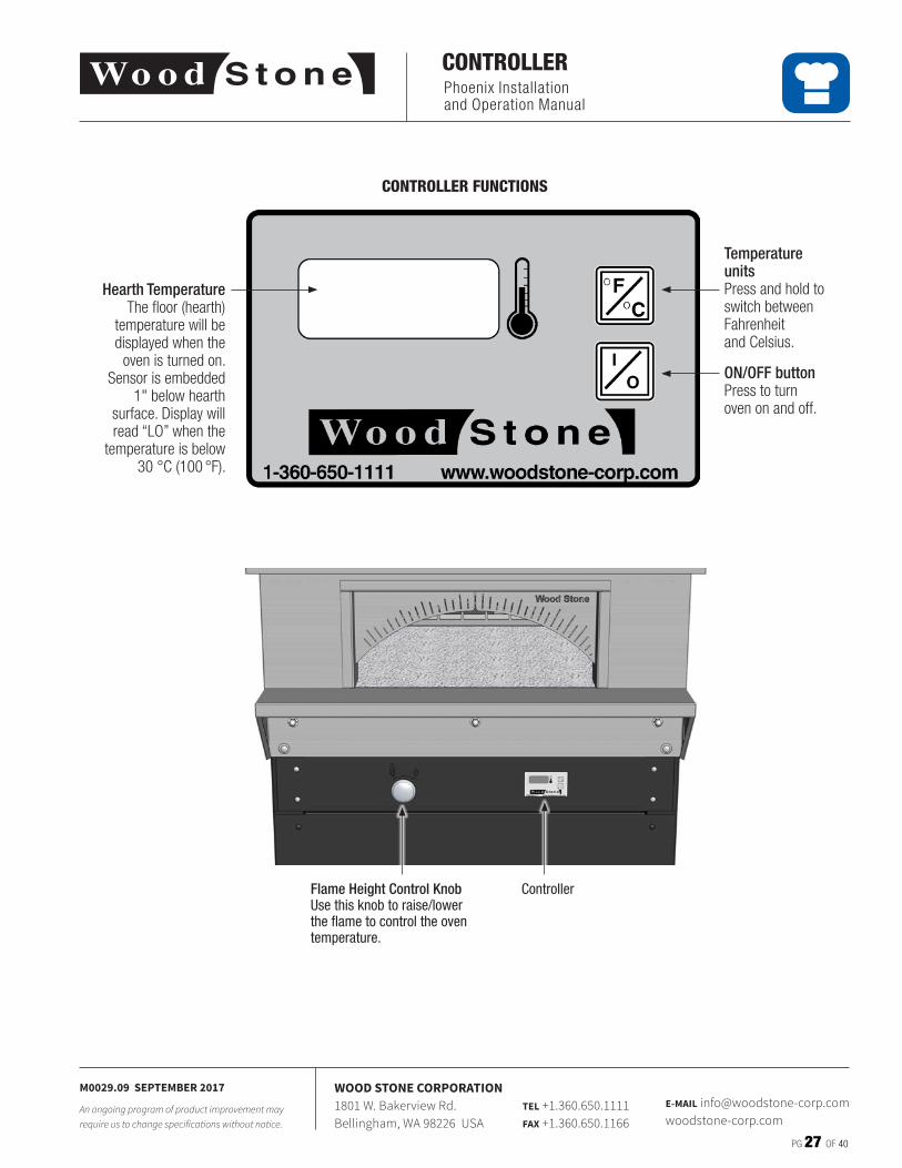
3. Remove the control box from the oven�
(4) 1/4-20 screws
4. Using the upper forklift pockets support the oven with a forklift or other suitable device� Remove the bolts that attach the oven body to the stand� Lift the oven off of the stand and place it on blocks as shown in the LIFTING THE OVEN section� Disassemble the stand if necessary� Follow the assembly instructions in the ASSEMBLY section to reassemble the oven�
Phoenix Installation and Operation Manual
PG 27 OF 40
M0029.09 SEPTEMBER 2017
An ongoing program of product improvement may require us to change specifications without notice.
WOOD STONE CORPORATION1801 W. Bakerview Rd.Bellingham, WA 98226 USA
TEL +1.360.650.1111FAX +1.360.650.1166
E-MAIL [email protected]
CONTROLLER
CONTROLLER FUNCTIONS
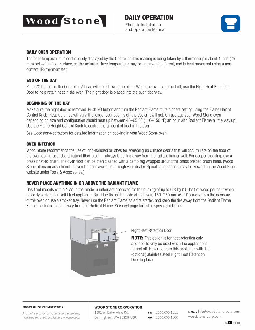
ON/OFF buttonPress to turn oven on and off�
Temperature unitsPress and hold to switch between Fahrenheit and Celsius�
Hearth TemperatureThe floor (hearth)
temperature will be displayed when the
oven is turned on� Sensor is embedded
1" below hearth surface� Display will read “LO” when the
temperature is below 30 °C (100 °F)�
Flame Height Control KnobUse this knob to raise/lower the flame to control the oven temperature.
Controller

Phoenix Installation and Operation Manual
PG 28 OF 40
M0029.09 SEPTEMBER 2017
An ongoing program of product improvement may require us to change specifications without notice.
WOOD STONE CORPORATION1801 W. Bakerview Rd.Bellingham, WA 98226 USA
TEL +1.360.650.1111FAX +1.360.650.1166
E-MAIL [email protected]
INITIAL START-UP
INITIAL OVEN START-UP
IMPORTANT: If at any time you feel that either or both of the burners are not operating properly, turn the oven off and call for service� Before servicing, disconnect the electrical supply at the breaker and turn off the gas supply at the appliance’s individual gas shutoff valve� In the event of a power failure, no attempt should be made to operate the oven�
Your oven was cured at the factory� However in the course of shipment, storage on site, etc� the ceramic materials will have absorbed moisture� It is critical that the initial oven Start-Up Procedure below be followed to ensure that this moisture is driven from the ceramic in a controlled fashion� This will minimize cracking and prevent damage to the oven that could otherwise occur by bringing the oven to temperature rapidly the first time it is used�
Occasionally, through the course of the initial start-up, as the oven heats up it is possible that you will see some water dripping from the sides of the oven as moisture is driven out of the ceramic� This is not a defect in the oven, and once the oven has been fully saturated with heat, the moisture will be driven fully from the oven�
This initial oven start-up procedure need only be followed the first time the oven is fired and/or if the oven has not been used for an extended period of time�
FIRST DAY1. Make sure exhaust fan is properly wired and interlocked to the appliance�2. Make sure main gas supply is ON (valve parallel with gas line)�3. Push I/O button on Controller� The exhaust fan should come on as well� It may take a while for the gas to purge all the air
from the gas lines�4. Once the burner ignites, make sure the flame is at its lowest setting and allow the appliance to operate at this setting for
about 1 hour�5. After 1 hour, using the Flame Height Control Knob, raise Radiant Flame to “2” on the Flame Height Index Scale�6. After 4 hours a raise to “3” on the Flame Height Index Scale and allow the appliance to run until it reaches a temperature of
260 °C (500 °F)� This will take approximately 3–4 hours�
NOTE: Small “crazing” cracks will occur with normal heating and cooling� They will not affect the performance or durability of the oven� If cracks of 3 mm (1/8") wide or more develop, contact Wood Stone for evaluation�
For more information regarding Flame Height Control, go to the Resource Center section of our web site at:www.woodstone-corp.com
Flame Height Index Scale
Flame Height Control Knob
FLAME HEIGHT INDICATORComprised of two parts
Phoenix Installation and Operation Manual
PG 29 OF 40
M0029.09 SEPTEMBER 2017
An ongoing program of product improvement may require us to change specifications without notice.
WOOD STONE CORPORATION1801 W. Bakerview Rd.Bellingham, WA 98226 USA
TEL +1.360.650.1111FAX +1.360.650.1166
E-MAIL [email protected]
DAILY OPERATION
DAILY OVEN OPERATIONThe floor temperature is continuously displayed by the Controller� This reading is being taken by a thermocouple about 1 inch (25 mm) below the floor surface, so the actual surface temperature may be somewhat different, and is best measured using a non-contact (IR) thermometer�
END OF THE DAYPush I/O button on the Controller� All gas will go off, even the pilots� When the oven is turned off, use the Night Heat Retention Door to help retain heat in the oven� The night door is placed into the oven doorway�
BEGINNING OF THE DAYMake sure the night door is removed� Push I/O button and turn the Radiant Flame to its highest setting using the Flame Height Control Knob� Heat-up times will vary, the longer your oven is off the cooler it will get� On average your Wood Stone oven depending on size and configuration should heat up between 43–65 °C (110–150 °F) an hour with Radiant Flame all the way up� Use the Flame Height Control Knob to control the amount of heat in the oven�
See woodstone-corp�com for detailed information on cooking in your Wood Stone oven�
OVEN INTERIORWood Stone recommends the use of long-handled brushes for sweeping up surface debris that will accumulate on the floor of the oven during use� Use a natural fiber brush—always brushing away from the radiant burner well� For deeper cleaning, use a brass bristled brush� The oven floor can be then cleaned with a damp rag wrapped around the brass bristled brush head� (Wood Stone offers an assortment of oven brushes available through your dealer� Specification sheets may be viewed on the Wood Stone website under Tools & Accessories�)
NEVER PLACE ANYTHING IN OR ABOVE THE RADIANT FLAMEGas fired models with a “-W” in the model number are approved for the burning of up to 6�8 kg (15 lbs�) of wood per hour when properly vented as a solid fuel appliance� Build the fire on the side of the oven, 150–250 mm (6–10") away from the doorway of the oven or use a smoker tray� Never use the Radiant Flame as a fire starter, and keep the fire away from the Radiant Flame� Keep all ash and debris away from the Radiant Flame� See next page for ash disposal guidelines�
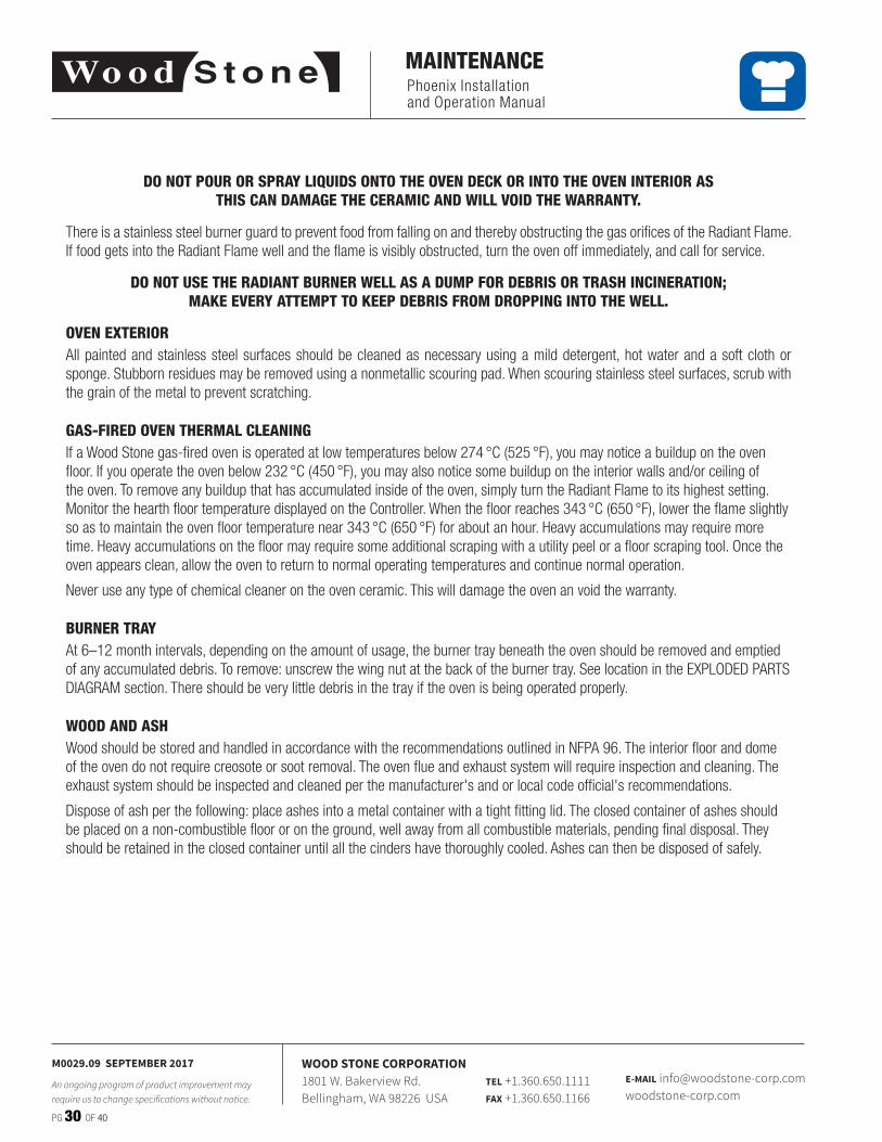
Night Heat Retention Door
NOTE: This option is for heat retention only, and should only be used when the appliance is turned off� Never operate this appliance with the (optional) stainless steel Night Heat Retention Door in place�
Phoenix Installation and Operation Manual
PG 30 OF 40
M0029.09 SEPTEMBER 2017
An ongoing program of product improvement may require us to change specifications without notice.
WOOD STONE CORPORATION1801 W. Bakerview Rd.Bellingham, WA 98226 USA
TEL +1.360.650.1111FAX +1.360.650.1166
E-MAIL [email protected]
MAINTENANCE
DO NOT POUR OR SPRAY LIQUIDS ONTO THE OVEN DECK OR INTO THE OVEN INTERIOR AS THIS CAN DAMAGE THE CERAMIC AND WILL VOID THE WARRANTY.
There is a stainless steel burner guard to prevent food from falling on and thereby obstructing the gas orifices of the Radiant Flame� If food gets into the Radiant Flame well and the flame is visibly obstructed, turn the oven off immediately, and call for service�
DO NOT USE THE RADIANT BURNER WELL AS A DUMP FOR DEBRIS OR TRASH INCINERATION; MAKE EVERY ATTEMPT TO KEEP DEBRIS FROM DROPPING INTO THE WELL.
OVEN EXTERIORAll painted and stainless steel surfaces should be cleaned as necessary using a mild detergent, hot water and a soft cloth or sponge� Stubborn residues may be removed using a nonmetallic scouring pad� When scouring stainless steel surfaces, scrub with the grain of the metal to prevent scratching�
GAS-FIRED OVEN THERMAL CLEANINGIf a Wood Stone gas-fired oven is operated at low temperatures below 274 °C (525 °F), you may notice a buildup on the oven floor� If you operate the oven below 232 °C (450 °F), you may also notice some buildup on the interior walls and/or ceiling of the oven� To remove any buildup that has accumulated inside of the oven, simply turn the Radiant Flame to its highest setting� Monitor the hearth floor temperature displayed on the Controller� When the floor reaches 343 °C (650 °F), lower the flame slightly so as to maintain the oven floor temperature near 343 °C (650 °F) for about an hour� Heavy accumulations may require more time� Heavy accumulations on the floor may require some additional scraping with a utility peel or a floor scraping tool� Once the oven appears clean, allow the oven to return to normal operating temperatures and continue normal operation�
Never use any type of chemical cleaner on the oven ceramic� This will damage the oven an void the warranty�
BURNER TRAYAt 6–12 month intervals, depending on the amount of usage, the burner tray beneath the oven should be removed and emptied of any accumulated debris� To remove: unscrew the wing nut at the back of the burner tray� See location in the EXPLODED PARTS DIAGRAM section� There should be very little debris in the tray if the oven is being operated properly�
WOOD AND ASHWood should be stored and handled in accordance with the recommendations outlined in NFPA 96� The interior floor and dome of the oven do not require creosote or soot removal� The oven flue and exhaust system will require inspection and cleaning� The exhaust system should be inspected and cleaned per the manufacturer's and or local code official's recommendations�
Dispose of ash per the following: place ashes into a metal container with a tight fitting lid� The closed container of ashes should be placed on a non-combustible floor or on the ground, well away from all combustible materials, pending final disposal� They should be retained in the closed container until all the cinders have thoroughly cooled� Ashes can then be disposed of safely�
Phoenix Installation and Operation Manual
PG 31 OF 40
M0029.09 SEPTEMBER 2017
An ongoing program of product improvement may require us to change specifications without notice.
WOOD STONE CORPORATION1801 W. Bakerview Rd.Bellingham, WA 98226 USA
TEL +1.360.650.1111FAX +1.360.650.1166
E-MAIL [email protected]
TROUBLESHOOTING GUIDE
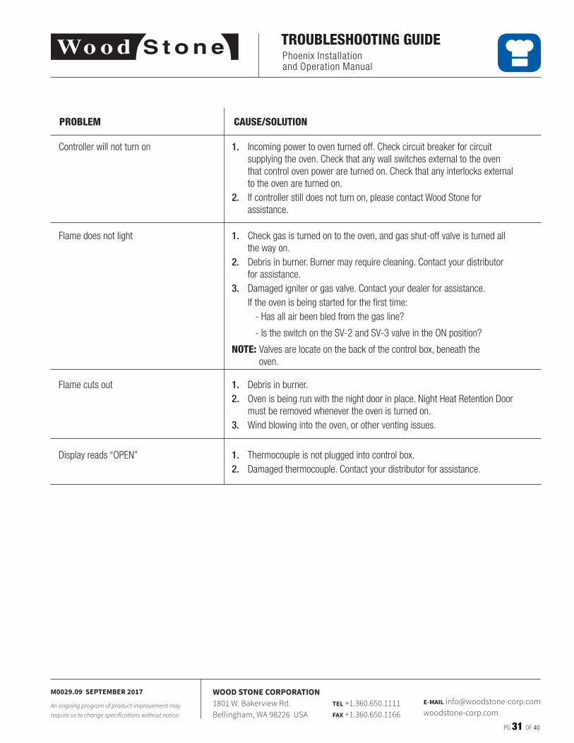
Controller will not turn on
Flame does not light
Flame cuts out
Display reads “OPEN”
1. Incoming power to oven turned off� Check circuit breaker for circuit supplying the oven� Check that any wall switches external to the oven that control oven power are turned on� Check that any interlocks external to the oven are turned on�
2. If controller still does not turn on, please contact Wood Stone for assistance�
1. Debris in burner�2. Oven is being run with the night door in place� Night Heat Retention Door
must be removed whenever the oven is turned on�3. Wind blowing into the oven, or other venting issues�
1. Thermocouple is not plugged into control box�2. Damaged thermocouple� Contact your distributor for assistance�
PROBLEM CAUSE/SOLUTION
1. Check gas is turned on to the oven, and gas shut-off valve is turned all the way on�
2. Debris in burner� Burner may require cleaning� Contact your distributor for assistance�
3. Damaged igniter or gas valve� Contact your dealer for assistance� If the oven is being started for the first time:
- Has all air been bled from the gas line?
- Is the switch on the SV-2 and SV-3 valve in the ON position?
NOTE: Valves are locate on the back of the control box, beneath the oven�
Phoenix Installation and Operation Manual
PG 32 OF 40
M0029.09 SEPTEMBER 2017
An ongoing program of product improvement may require us to change specifications without notice.
WOOD STONE CORPORATION1801 W. Bakerview Rd.Bellingham, WA 98226 USA
TEL +1.360.650.1111FAX +1.360.650.1166
E-MAIL [email protected]
WOOD BURNING
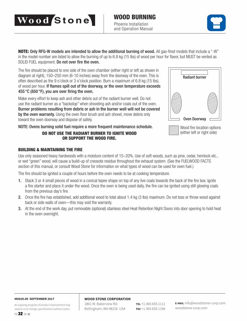
NOTE: Only RFG-W models are intended to allow the additional burning of wood. All gas-fired models that include a “-W” in the model number are listed to allow the burning of up to 6�8 kg (15 lbs) of wood per hour for flavor, but MUST be vented as SOLID FUEL equipment� Do not over fire the oven.
Wood fire location options (either left or right side)
Oven Doorway
Radiant burner
The fire should be placed to one side of the oven chamber (either right or left as shown in diagram at right), 150–250 mm (6-10 inches) away from the doorway of the oven� This is often described as the 9 o’clock or 3 o’clock position� Burn a maximum of 6�8 kg (15 lbs)� of wood per hour� If flames spill out of the doorway, or the oven temperature exceeds 455 °C (850 °F), you are over firing the oven.
Make every effort to keep ash and other debris out of the radiant burner well� Do not use the radiant burner as a “backstop” when shoveling ash and/or coals out of the oven� Burner problems resulting from debris or ash in the burner well will not be covered by the oven warranty. Using the oven floor brush and ash shovel, move debris only toward the oven doorway and dispose of safely�
NOTE: Ovens burning solid fuel require a more frequent maintenance schedule.
DO NOT USE THE RADIANT BURNER TO IGNITE WOOD OR SUPPORT THE WOOD FIRE.
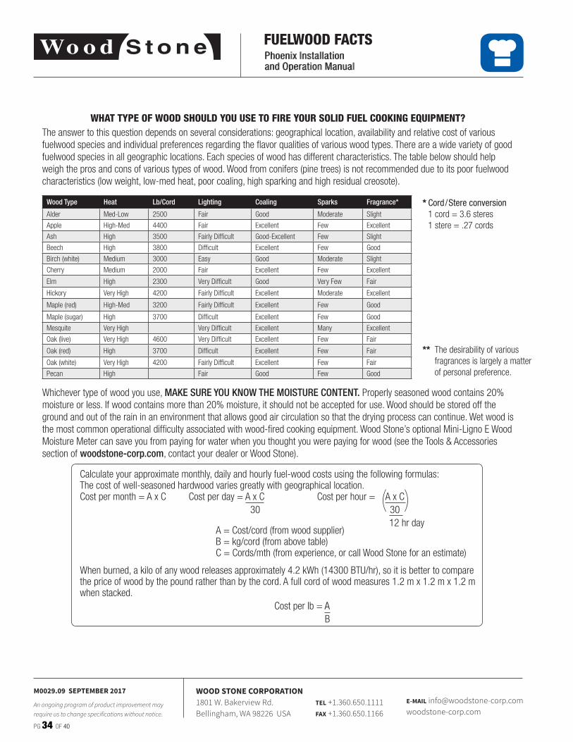
BUILDING & MAINTAINING THE FIREUse only seasoned heavy hardwoods with a moisture content of 15–20%� Use of soft woods, such as pine, cedar, hemlock etc�, or wet “green” wood, will cause a build-up of creosote residue throughout the exhaust system� (See the FUELWOOD FACTS section of this manual, or consult Wood Stone for information on what types of wood can be used for oven fuel�)
The fire should be ignited a couple of hours before the oven needs to be at cooking temperature�
1. Stack 3 or 4 small pieces of wood in a conical tepee shape on top of any live coals towards the back of the fire box� Ignite a fire starter and place it under the wood� Once the oven is being used daily, the fire can be ignited using still glowing coals from the previous day’s fire�
2. Once the fire has established, add additional wood to total about 1�4 kg (3 lbs) maximum� Do not toss or throw wood against back or side walls of oven—this may void the warranty�
3. At the end of the work day, put removable (optional) stainless steel Heat Retention Night Doors into door opening to hold heat in the oven overnight�
Phoenix Installation and Operation Manual
PG 33 OF 40
M0029.09 SEPTEMBER 2017
An ongoing program of product improvement may require us to change specifications without notice.
WOOD STONE CORPORATION1801 W. Bakerview Rd.Bellingham, WA 98226 USA
TEL +1.360.650.1111FAX +1.360.650.1166
E-MAIL [email protected]
WOOD BURNING
As with all commercial cooking equipment exhaust systems, a regular inspection and cleaning schedule is needed to prevent the possibility of a hood or duct fire� The frequency of inspection and cleaning will depend on hours of use and type and quality of wood used as fuel� Only use hardwood species dried to a moisture content of 20% or less�
CREOSOTE: FORMATION AND NEED FOR REMOVALWhen wood is burned slowly, it produces tar and other organic vapors, which combine with expelled moisture to form creosote� The creosote vapors condense in the relatively cool oven flue of a slow-burning fire� As a result, creosote residue accumulates in the duct� When ignited, this creosote makes an extremely hot fire�
The duct serving this oven should be inspected at least twice a month during the first two months of operation to establish a rate of creosote buildup and necessary cleaning schedule� If creosote or soot has accumulated, it should be removed to reduce the risk of a flue fire�
The interior floor and dome of the oven do not require creosote or soot removal� The oven flue and exhaust system will require inspection and cleaning� The exhaust system must be inspected and cleaned per the manufacturer’s and or local code official’s recommendations� Wood Stone recommends cleaning and inspection at least monthly on any ventilation system serving solid fuel equipment.
DO NOT USE THE RADIANT BURNER TO IGNITE WOOD OR SUPPORT THE WOOD FIRE.
Wood should be stored and handled in accordance with the recommendations outlined in NFPA 96.
DISPOSE OF ASH PER THE FOLLOWING: 1. Place ashes into a metal container with a tight fitting lid�2. Place the closed container of ashes on a non-combustible floor or on the ground�3. Place the closed container of ashes well away from all combustible materials, pending final disposal�4. Retain the ashes in the closed container until all the cinders have thoroughly cooled� Ashes can then be disposed of safely�
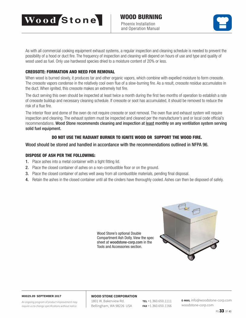
Wood Stone’s optional Double Compartment Ash Dolly. View the spec sheet at woodstone-corp.com in the Tools and Accessories section.
Phoenix Installation and Operation Manual
PG 34 OF 40
M0029.09 SEPTEMBER 2017
An ongoing program of product improvement may require us to change specifications without notice.
WOOD STONE CORPORATION1801 W. Bakerview Rd.Bellingham, WA 98226 USA
TEL +1.360.650.1111FAX +1.360.650.1166
E-MAIL [email protected]
Phoenix Installation and Operation Manual
FUELWOOD FACTS
WHAT TYPE OF WOOD SHOULD YOU USE TO FIRE YOUR SOLID FUEL COOKING EQUIPMENT?The answer to this question depends on several considerations: geographical location, availability and relative cost of various fuelwood species and individual preferences regarding the flavor qualities of various wood types� There are a wide variety of good fuelwood species in all geographic locations� Each species of wood has different characteristics� The table below should help weigh the pros and cons of various types of wood� Wood from conifers (pine trees) is not recommended due to its poor fuelwood characteristics (low weight, low-med heat, poor coaling, high sparking and high residual creosote)�
Whichever type of wood you use, MAKE SURE YOU KNOW THE MOISTURE CONTENT. Properly seasoned wood contains 20% moisture or less� If wood contains more than 20% moisture, it should not be accepted for use� Wood should be stored off the ground and out of the rain in an environment that allows good air circulation so that the drying process can continue� Wet wood is the most common operational difficulty associated with wood-fired cooking equipment� Wood Stone’s optional Mini-Ligno E Wood Moisture Meter can save you from paying for water when you thought you were paying for wood (see the Tools & Accessories section of woodstone-corp.com, contact your dealer or Wood Stone)�
** The desirability of various fragrances is largely a matter of personal preference�
Calculate your approximate monthly, daily and hourly fuel-wood costs using the following formulas:The cost of well-seasoned hardwood varies greatly with geographical location�Cost per month = A x C Cost per day = A x C Cost per hour = A x C 30 30 12 hr day A = Cost/cord (from wood supplier) B = kg/cord (from above table) C = Cords/mth (from experience, or call Wood Stone for an estimate)
When burned, a kilo of any wood releases approximately 4�2 kWh (14300 BTU/hr), so it is better to compare the price of wood by the pound rather than by the cord� A full cord of wood measures 1�2 m x 1�2 m x 1�2 m when stacked� Cost per lb = A B
( )
* Cord / Stere conversion 1 cord = 3�6 steres 1 stere = �27 cords
Wood Type Heat Lb/Cord Lighting Coaling Sparks Fragrance*
Alder Med-Low 2500 Fair Good Moderate Slight
Apple High-Med 4400 Fair Excellent Few Excellent
Ash High 3500 Fairly Difficult Good-Excellent Few Slight
Beech High 3800 Difficult Excellent Few Good
Birch (white) Medium 3000 Easy Good Moderate Slight
Cherry Medium 2000 Fair Excellent Few Excellent
Elm High 2300 Very Difficult Good Very Few Fair
Hickory Very High 4200 Fairly Difficult Excellent Moderate Excellent
Maple (red) High-Med 3200 Fairly Difficult Excellent Few Good
Maple (sugar) High 3700 Difficult Excellent Few Good
Mesquite Very High Very Difficult Excellent Many Excellent
Oak (live) Very High 4600 Very Difficult Excellent Few Fair
Oak (red) High 3700 Difficult Excellent Few Fair
Oak (white) Very High 4200 Fairly Difficult Excellent Few Fair
Pecan High Fair Good Few Good
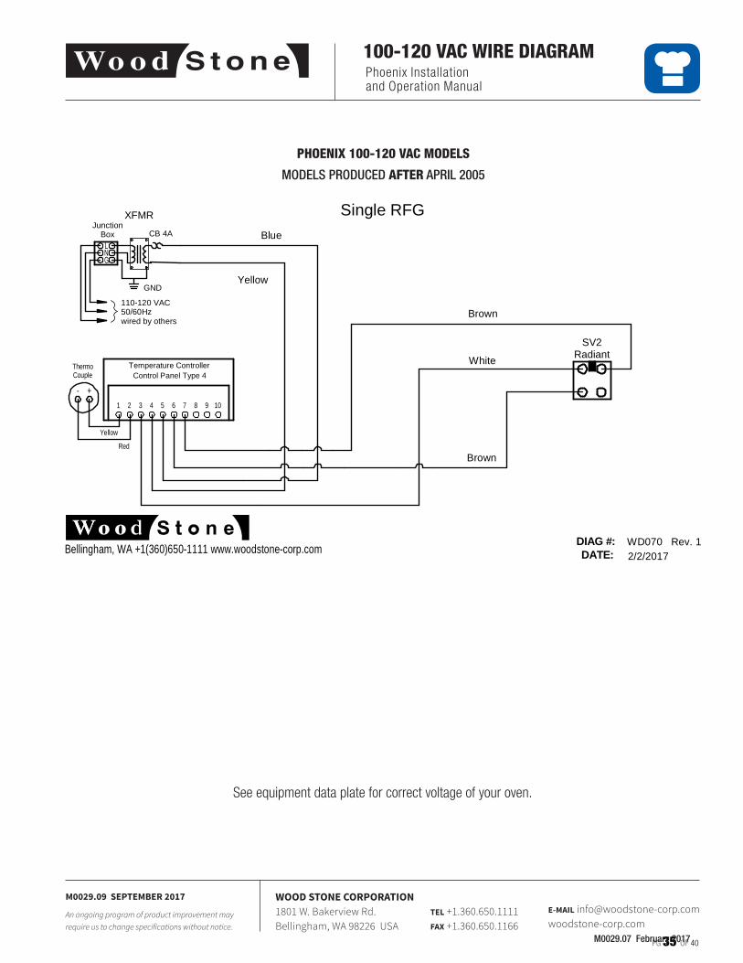
Phoenix Installation and Operation Manual
PG 35 OF 40
M0029.09 SEPTEMBER 2017
An ongoing program of product improvement may require us to change specifications without notice.
WOOD STONE CORPORATION1801 W. Bakerview Rd.Bellingham, WA 98226 USA
TEL +1.360.650.1111FAX +1.360.650.1166
E-MAIL [email protected]
100-120 VAC WIRE DIAGRAM
M0029.07 February 2017
PHOENIX 100-120 VAC MODELS
MODELS PRODUCED AFTER APRIL 2005
Single RFG
DATE:DIAG #: WD070 Rev. 1
2/2/2017Bellingham, WA +1(360)650-1111 www.woodstone-corp.com
RadiantSV2
JunctionBox
LNG
CB 4A
GND
XFMR
110-120 VAC50/60Hzwired by others
White
Brown
Brown
Blue
Yellow
Temperature ControllerControl Panel Type 4
10987654321
Yellow
Red
+-
ThermoCouple
See equipment data plate for correct voltage of your oven�
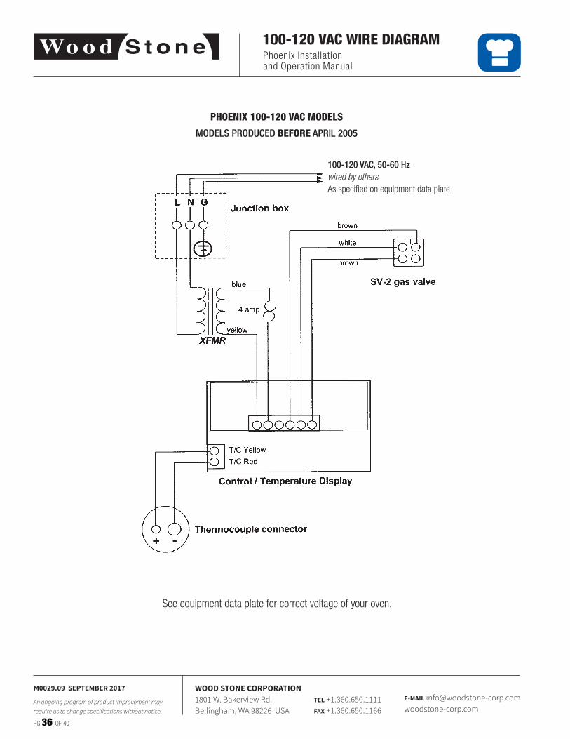
Phoenix Installation and Operation Manual
PG 36 OF 40
M0029.09 SEPTEMBER 2017
An ongoing program of product improvement may require us to change specifications without notice.
WOOD STONE CORPORATION1801 W. Bakerview Rd.Bellingham, WA 98226 USA
TEL +1.360.650.1111FAX +1.360.650.1166
E-MAIL [email protected]
100-120 VAC WIRE DIAGRAM
PHOENIX 100-120 VAC MODELS
MODELS PRODUCED BEFORE APRIL 2005
100-120 VAC, 50-60 Hzwired by othersAs specified on equipment data plate
See equipment data plate for correct voltage of your oven�
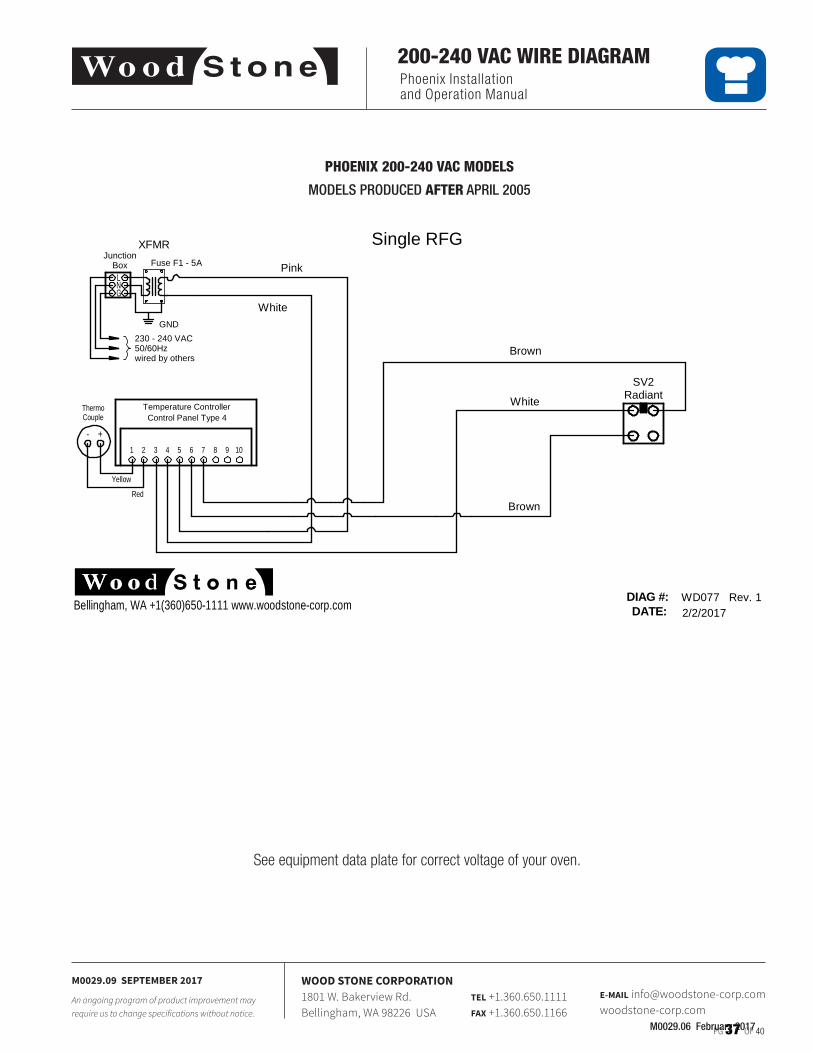
Phoenix Installation and Operation Manual
PG 37 OF 40
M0029.09 SEPTEMBER 2017
An ongoing program of product improvement may require us to change specifications without notice.
WOOD STONE CORPORATION1801 W. Bakerview Rd.Bellingham, WA 98226 USA
TEL +1.360.650.1111FAX +1.360.650.1166
E-MAIL [email protected]
200-240 VAC WIRE DIAGRAM
M0029.06 February 2017
See equipment data plate for correct voltage of your oven�
PHOENIX 200-240 VAC MODELS
MODELS PRODUCED AFTER APRIL 2005
Single RFG
DATE:DIAG #: WD077 Rev. 1
2/2/2017Bellingham, WA +1(360)650-1111 www.woodstone-corp.com
RadiantSV2
JunctionBox
LNG
Fuse F1 - 5A
GND
XFMR
230 - 240 VAC50/60Hzwired by others
White
Brown
Brown
Pink
White
Temperature ControllerControl Panel Type 4
10987654321
Yellow
Red
+-
ThermoCouple
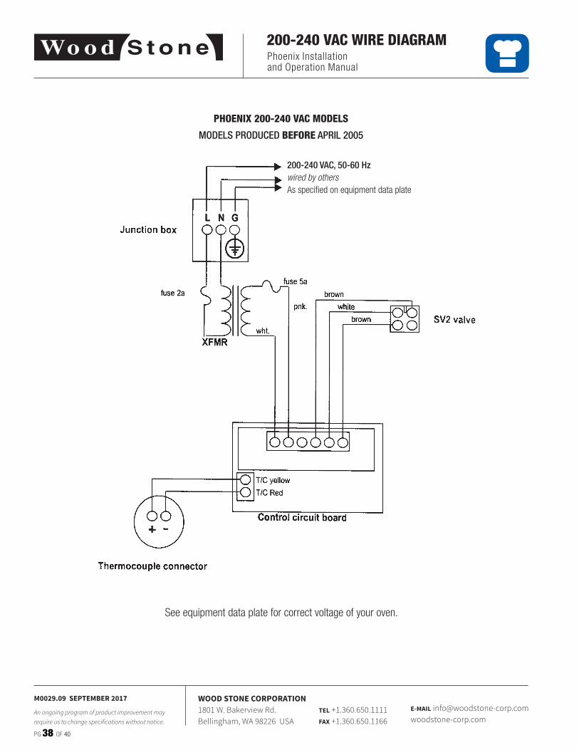
Phoenix Installation and Operation Manual
PG 38 OF 40
M0029.09 SEPTEMBER 2017
An ongoing program of product improvement may require us to change specifications without notice.
WOOD STONE CORPORATION1801 W. Bakerview Rd.Bellingham, WA 98226 USA
TEL +1.360.650.1111FAX +1.360.650.1166
E-MAIL [email protected]
200-240 VAC WIRE DIAGRAM
PHOENIX 200-240 VAC MODELS
MODELS PRODUCED BEFORE APRIL 2005
200-240 VAC as specified on dataplate
See equipment data plate for correct voltage of your oven�
200-240 VAC, 50-60 Hzwired by othersAs specified on equipment data plate

Phoenix Installation and Operation Manual
PG 39 OF 40
M0029.09 SEPTEMBER 2017
An ongoing program of product improvement may require us to change specifications without notice.
WOOD STONE CORPORATION1801 W. Bakerview Rd.Bellingham, WA 98226 USA
TEL +1.360.650.1111FAX +1.360.650.1166
E-MAIL [email protected]
LIMITED WARRANTY
WOOD STONE WARRANTS ITS EQUIPMENT TO THE ORIGINAL PURCHASER AGAINST DEFECTS IN MATERIAL OR MANUFACTURE FOR A PERIOD OF ONE YEAR FROM THE ORIGINAL
DATE OF PURCHASE, SUBJECT TO THE FOLLOWING EXCLUSIONS AND LIMITATIONS.
CONTACT YOUR LOCAL DISTRIBUTOR FOR WARRANTY SERVICE
EXCLUSIONSThe warranties provided by Wood Stone do not apply in the following instances:1� In the event that the equipment is improperly installed� Proper installation is the responsibility of the installer; proper installation
procedures are prescribed by the Wood Stone Installation and Operation Manual�2� In the event the equipment is improperly or inadequately maintained� Proper maintenance is the responsibility of the user; proper
maintenance procedures are prescribed in the Wood Stone Installation and Operation Manual� Burner problems resulting from debris or ash in the burner well will not be covered by the warranty� Call with questions regarding maintenance frequency�
3� In the event that the failure or malfunction of the appliance or any part thereof is caused by abnormal or improper use or is otherwise not attributable to defect in material or manufacture�
4� In the event that the appliance, by whatever cause, has been materially altered from the condition in which it left the factory�5� In the event that the rating plate has been removed, altered or obliterated�6� On parts that would be normally worn or replaced under normal conditions�7� Normal cracking due to expansion and contraction stress relief in the ceramic firebox�8� In wood-fired equipment configurations, in the event that pressed log products of any type have been burned in the equipment�9� In coal-fired oven configurations, in the event any type of coal other than anthracite coal fuel has been used� 10� Damage resulting from the use of chemical cleaning products in the oven, as well as any damage from liquids or chemicals, including
water, being poured or sprayed into the oven�
If any oral statements have been made regarding this appliance, such statements do not constitute warranties and are not part of the contract of sale� This Limited Warranty constitutes the complete, final and exclusive statement with regard to warranties�
THIS LIMITED WARRANTY IS EXCLUSIVE AND IN LIEU OF ALL OTHER WARRANTIES WHETHER WRITTEN, ORAL OR IMPLIED, INCLUDING, BUT NOT LIMITED TO, ANY WARRANTY OF MERCHANTABILITY OR FITNESS FOR PARTICULAR PURPOSE OR WARRANTY AGAINST LATENT DEFECTS.
LIMITATIONS OF LIABILITYIn the event of warranty claim or otherwise, the sole obligation of Wood Stone shall be the repair and/or replacement, at the option of Wood Stone, of the appliance or component or part thereof� Such repair or replacement shall be at the expense of Wood Stone with the exception of travel over 100 miles or two hours, overtime, and holiday charges which shall be at the expense of the purchaser� Any repair or replacement under this warranty does not constitute an extension of the original warranty for any period of the appliance or for any component or part thereof� Parts to be replaced under this warranty will be repaired or replaced at the option of Wood Stone with new or functionally operative parts� The liability of Wood Stone on any claim of any kind, including claims based on warranty, expressed or implied, contract, negligence, strict liability or any other theories shall be solely and exclusively the repair or replacement of the product as stated herein, and such liability shall not include, and purchaser specifically renounces any rights to recover, special, incidental, consequential or other damages of any kind whatsoever, including, but not limited to, injuries to persons or damage to property, loss of profits or anticipated profits, or loss of use of the product�
TO SECURE WARRANTY SERVICEIf you claim a defect covered by this Limited Warranty, contact your local distributor�

PG 40 OF 40 M0029.09 SEPTEMBER 2017
Tel +1.360.650.1111
Fax +1.360.650.1166
www.woodstone-corp.com
WOOD STONE CORPORATION1801 W. Bakerview Rd.
Bellingham, WA 98226 USA
An ongoing program of product improvement may require us to change specifications without notice.