installation and operational instructions for roba -ds ... · roba®-ds coupling for measurement...
TRANSCRIPT

Installation and Operational Instructions for ROBA®-DS Coupling for Measurement Flange Connection Type 9_10._ _ _ _0 Sizes 16F / 16 / 64 / 300 / 500 / 850 (B.9110.EN)
19/10/2017 TK/GH/WT/SU Chr. Mayr GmbH + Co. KG Eichenstraße 1, D-87665 Mauerstetten, Germany Tel.: +49 8341 804-0, Fax: +49 8341 804-421 Page 1 of 14 www.mayr.com, E-Mail: [email protected]
Please read these Operational Instructions carefully and follow them accordingly!
Ignoring these Instructions may lead to malfunctions or to coupling failure, resulting in damage to other parts.
Contents:
Page 1: - Contents - Safety and Guideline Signs - Safety Regulations
Page 2: - Coupling Illustrations Type 9110._ _ _00
Page 3: - Coupling Illustrations Type 9110._ _ 0_0
Page 4: - Coupling Illustrations Type 9110._ _ 330
Page 5: - Coupling Illustrations Type 9210._ _ _00
Page 6: - Parts List
Page 7: - Technical Data
Page 8: - Overview of Screws and Tightening Torques
Page 9: - Transmittable Torques of the Shrink Disk Hubs
Page 10: - Function - Application - Design - State of Delivery - Coupling Application Field - Storage - General Installation Guidelines - Max. Screw-in Depths for Customer-side Screws - Hub Installation
Page 11: - Assignment of the Torque Transducers - Installation of the Coupling in the Drive Line - Type 9110._ _ _00 - Type 9110._ _ 0_0
Page 12: - Installation of the Coupling in the Drive Line - Type 9110._ _ 330 - Type 9210._ _ _00 - Disk Pack Installation
Page 13: - Coupling Alignment - Permitted Shaft Misalignments - Maintenance - Disposal
Page 14: - Malfunctions / Breakdowns
Safety and Guideline Signs
CAUTION
Danger of injury to personnel and damage to machines.
Please Observe! Guidelines on important points.
Safety Regulations
These Installation and Operational Instructions (I + O) are part of the coupling delivery. Please keep them handy and near to the coupling at all times.
It is forbidden to start initial operation of the product until you have ensured that all applicable EU directives and directives for the machine or system, into which the product has been installed, have been fulfilled. At the time these Installation and Operational Instructions go to print, the ROBA®-DS couplings accord with the known technical specifications and are operationally safe at the time of delivery. Without a conformity evaluation, this product is not suitable for use in areas where there is a high danger of explosion. This statement is based on the ATEX directive.
CAUTION If the ROBA®-DS couplings are modified.
The relevant standards for safety and / or installation conditions are ignored.
User-implemented Protective Measures
Cover all moving parts to protect against seizure, dust or foreign body impact.
To prevent injury or damage, only professionals and specialists should work on the devices, following the relevant standards and directives. Please read the Installation and Operational Instructions carefully prior to installation and initial operation of the device.
These Safety Regulations are user hints only and may not be complete!

Installation and Operational Instructions for ROBA®-DS Coupling for Measurement Flange Connection Type 9_10._ _ _ _0 Sizes 16F / 16 / 64 / 300 / 500 / 850 (B.9110.EN)
19/10/2017 TK/GH/WT/SU Chr. Mayr GmbH + Co. KG Eichenstraße 1, D-87665 Mauerstetten, Germany Tel.: +49 8341 804-0, Fax: +49 8341 804-421 Page 2 of 14 www.mayr.com, E-Mail: [email protected]
Type 9110._ _ _00
Side 1 Side 2
Fig. 1
1 1
16
16
6
6
10
9
1.1 1.1
6
13 13
11
16
16
9
6 6
5
5
16
16 16
16
16
9
9 94
9
12
3
3
331.2 1.2
10
6
Without hub
Module 1, sleeve
Measurement flange
Without hub
Shrink disk hub clamping external
Shrink disk hub clamping external
Module 1, connection plate
Sizes 16F to 300
Sizes 500 / 850
The shrink disk hub (side 1) with module 1 is supplied as a finished assembly.
Installation and Operational Instructions for ROBA®-DS Coupling for Measurement Flange Connection Type 9_10._ _ _ _0 Sizes 16F / 16 / 64 / 300 / 500 / 850 (B.9110.EN)
19/10/2017 TK/GH/WT/SU Chr. Mayr GmbH + Co. KG Eichenstraße 1, D-87665 Mauerstetten, Germany Tel.: +49 8341 804-0, Fax: +49 8341 804-421 Page 3 of 14 www.mayr.com, E-Mail: [email protected]
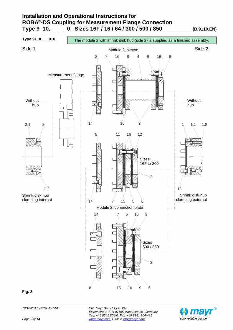
Type 9110. _ _0_0
Side 1 Side 2
Fig. 2
2 1
16
16
12
95
1.1
11
7
2.2 13
14
8
14
7
15
7 6
15
9
15
16 16
5
16
9 94
6
6
3
3
32.1 1.2
8
14
8
Without hub
Module 2, sleeve
Measurement flange
Without hub
Shrink disk hub clamping internal
Shrink disk hub clamping external
Module 2, connection plate
Sizes 16F to 300
Sizes 500 / 850
The module 2 with shrink disk hub (side 2) is supplied as a finished assembly.
Installation and Operational Instructions for ROBA®-DS Coupling for Measurement Flange Connection Type 9_10._ _ _ _0 Sizes 16F / 16 / 64 / 300 / 500 / 850 (B.9110.EN)
19/10/2017 TK/GH/WT/SU Chr. Mayr GmbH + Co. KG Eichenstraße 1, D-87665 Mauerstetten, Germany Tel.: +49 8341 804-0, Fax: +49 8341 804-421 Page 4 of 14 www.mayr.com, E-Mail: [email protected]
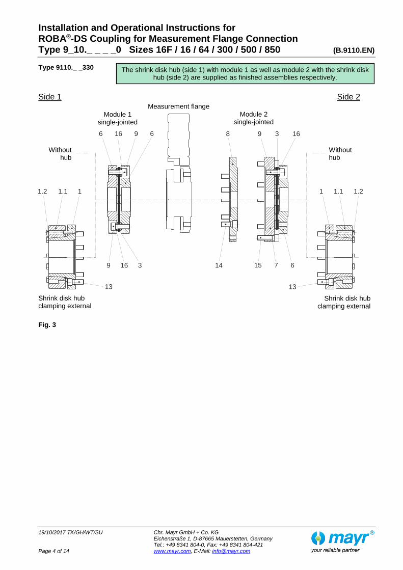
Type 9110._ _330
Side 1 Side 2
Fig. 3
1 11.1 1.1
13 13
6
16
16
3
9 6
9
1.2 1.2
9 1638
14 15 7 6
Without hub
Module 1 single-jointed
Measurement flange
Without hub
Shrink disk hub clamping external
Shrink disk hub clamping external
Module 2 single-jointed
The shrink disk hub (side 1) with module 1 as well as module 2 with the shrink disk hub (side 2) are supplied as finished assemblies respectively.

Installation and Operational Instructions for ROBA®-DS Coupling for Measurement Flange Connection Type 9_10._ _ _ _0 Sizes 16F / 16 / 64 / 300 / 500 / 850 (B.9110.EN)
19/10/2017 TK/GH/WT/SU Chr. Mayr GmbH + Co. KG Eichenstraße 1, D-87665 Mauerstetten, Germany Tel.: +49 8341 804-0, Fax: +49 8341 804-421 Page 5 of 14 www.mayr.com, E-Mail: [email protected]
Type 9210._ _ _00
Side 1 Side 2
Fig. 4
1 11.1 1.1
13 13
1.2 1.2
16
16
6
6
10
9
6
11
16
16
9
5
5
16 12
3
3
10
6
Without hub
Measurement flange
Without hub
Shrink disk hub clamping external
Shrink disk hub clamping external
Module 1, connection plate
Sizes 16F to 300
Sizes 500 / 850
The shrink disk hub (side 1) with module 1 is supplied as a finished assembly.

Installation and Operational Instructions for ROBA®-DS Coupling for Measurement Flange Connection Type 9_10._ _ _ _0 Sizes 16F / 16 / 64 / 300 / 500 / 850 (B.9110.EN)
19/10/2017 TK/GH/WT/SU Chr. Mayr GmbH + Co. KG Eichenstraße 1, D-87665 Mauerstetten, Germany Tel.: +49 8341 804-0, Fax: +49 8341 804-421 Page 6 of 14 www.mayr.com, E-Mail: [email protected]
Parts List (Only use mayr ® original parts)
Item Name
1 Shrink disk hub / clamping external
1.1 Shrink disk
1.2 Hexagon head screw
2 Shrink disk hub / clamping internal
2.1 Shrink disk
2.2 Cap screw
3 Disk pack
4 Sleeve
5 Connection plate
6 Flange MF
7 Flange
8 Adaptor flange MF
9 Cap screw
10 Hexagon head screw (only on Sizes 16F, 16, 64 and 300)
11 Cap screw (only on Sizes 16F, 16, 64 and 300)
12 Hexagon nut (only on Sizes 16F, 16, 64 and 300)
13 Cap screw
14 Cap screw
15 Cap screw
16 Washer

Installation and Operational Instructions for ROBA®-DS Coupling for Measurement Flange Connection Type 9_10._ _ _ _0 Sizes 16F / 16 / 64 / 300 / 500 / 850 (B.9110.EN)
19/10/2017 TK/GH/WT/SU Chr. Mayr GmbH + Co. KG Eichenstraße 1, D-87665 Mauerstetten, Germany Tel.: +49 8341 804-0, Fax: +49 8341 804-421 Page 7 of 14 www.mayr.com, E-Mail: [email protected]
Table 1: Technical Data for Type 9110._ _ _ _0
ROBA®-DS Size 16F 16 64 300 500 850
Sensor measuring range [Nm] 50 / 100 200 500 / 1000 2000 / 3000 5000 10000
Minimum hub bore (Items 1 and 2) d min [mm] 25 H6 25 H6 45 H6 50 H6 60 H6 70 H6
Maximum hub bore (Items 1 and 2) d max [mm] 45 H6 45 H6 70 H6 85 H6 100 H6 120 H6
Coupling nominal torque TKN Valid for changing load direction as well as for max. permitted shaft misalignment
[Nm] 190 300 1100 3500 5800 9500
Coupling peak torque TKS Valid for unchanging load direction, max. load cycle ≤ 105
[Nm] 285 450 1650 5250 8700 14250
Max. speed 1) n max [rpm] 18000 18000 15000 12000 10000 8000
Distance dimension S [mm] 7.1 0.1 4.6 0.1 6.8 0.15 11.2 0.15 12 0.15 14 0.15
Axial displacement ΔKa Only permitted as a static or virtually static value.
[mm] ±1.1 ±0.8 ±1.1 ±1.2 ±1.4 ±1.6
Max. permitted radial misalignment ΔKr
With connection plate [mm] 0.30 0.20 0.25 0.25 0.35 0.40
Max. permitted radial misalignment ΔKr
With sleeve [mm] 1.0 0.7 1.0 1.25 1.35 1.7
Max. permitted angular misalignment ΔKw (per disk pack)
[°] 1.0 0.7 0.6 0.5 0.5 0.5
1) For speeds more than 5000 rpm, a limitation of the misalignment to max. 30 % is necessary. The values then correspond to the permitted misalignment values on Type 9210._ _ _00 acc. Table 2.
Table 2: Technical Data for Type 9210._ _ _00
ROBA®-DS Size 16F 16 64 300 500 850
Sensor measuring range [Nm] 50 / 100 200 500 / 1000 2000 / 3000 5000 10000
Minimum hub bore (Items 1 and 2) d min [mm] 25 H5 25 H5 45 H5 50 H5 60 H5 70 H5
Maximum hub bore (Items 1 and 2) d max [mm] 45 H5 45 H5 70 H5 85 H5 100 H5 120 H5
Coupling nominal torque TKN Valid for changing load direction as well as for max. permitted shaft misalignment
[Nm] 190 300 1100 3500 5800 9500
Coupling peak torque TKS Valid for unchanging load direction, max. load cycle ≤ 105
[Nm] 285 450 1650 5250 8700 14250
Max. speed n max [rpm] 30000 30000 25000 20000 16000 13000
Distance dimension S [mm] 7.1 0.1 4.6 0.1 6.8 0.15 11.2 0.15 12 0.15 14 0.15
Max. permitted axial displacement ΔKa Only permitted as a static or virtually static value.
[mm] ±0.2 ±0.2 ±0.3 ±0.4 ±0.4 ±0.5
Max. permitted radial misalignment ΔKr [mm] 0.06 0.06 0.08 0.08 0.11 0.13
Max. permitted angular misalignment ΔKw (per disk pack)
[°] 0.3 0.2 0.2 0.16 0.16 0.16

Installation and Operational Instructions for ROBA®-DS Coupling for Measurement Flange Connection Type 9_10._ _ _ _0 Sizes 16F / 16 / 64 / 300 / 500 / 850 (B.9110.EN)
19/10/2017 TK/GH/WT/SU Chr. Mayr GmbH + Co. KG Eichenstraße 1, D-87665 Mauerstetten, Germany Tel.: +49 8341 804-0, Fax: +49 8341 804-421 Page 8 of 14 www.mayr.com, E-Mail: [email protected]
Table 3: Overview of Screws and Respective Tightening Torques
ROBA®-DS Size 16F 16 64 300 500 850
Hexagon head screws Item 1.2 Tightening torque
M5 x 30
6 Nm
M5 x 30
6 Nm
M8 x 55
24 Nm
M8 x 60
35 Nm
M10 x 70
56 Nm
M12 x 80
93 Nm
Cap screws Item 2.2 Tightening torque
M5 x 18
6 Nm
M5 x 18
6 Nm
M8 x 30
24 Nm
M8 x 30
35 Nm
M10 x 40
56 Nm
M12 x 40
93 Nm
Cap screws Item 9 2) Tightening torque
M5 x 18
8.5 Nm
M5 x 16
8.5 Nm
M8 x 25
35 Nm
M12 x 35
120 Nm
M16 x 40
240 Nm
M20 x 45
450 Nm
Hexagon head screws Item 10 2) Tightening torque
M5 x 18
8.5 Nm
M5 x 16
8.5 Nm
M8 x 25
35 Nm
M12 x 35
120 Nm -
- -
Cap screws Item 11 / Hexagon nut Item 12 Tightening torque
M5 x 35 M5
8.5 Nm
M5 x 32 M5
8.5 Nm
M8 x 45 M8
35 Nm
M12 x 65 M12
120 Nm
- -
Cap screws Item 13 2) 3) Tightening torque
M8 x 14
34 Nm
M8 x 14
34 Nm
M10 x 20
67 Nm
M12 x 30
135 Nm
M14 x 30
220 Nm
M16 x 40
340 Nm
Cap screws Item 14 2) 3) Tightening torque
M8 x 25
34 Nm
M8 x 25
34 Nm
M10 x 20
67 Nm
M12 x 30
135 Nm
M14 x 35
220 Nm
M16 x 35
340 Nm
Cap screws Item 15 2) Tightening torque
M8 x 16
34 Nm
M8 x 16
34 Nm
M8 x 25
37 Nm
M12 x 40
127 Nm
M12 x 50
127 Nm
M14 x 50
174 Nm
2) The screws (Items 9, 10, 13, 14 and 15) must be protected using a screw-securing product, e.g. Loctite 243. 3) For this, please also observe the guidelines in the Installation Instructions of the measurement flange manufacturer.

Installation and Operational Instructions for ROBA®-DS Coupling for Measurement Flange Connection Type 9_10._ _ _ _0 Sizes 16F / 16 / 64 / 300 / 500 / 850 (B.9110.EN)
19/10/2017 TK/GH/WT/SU Chr. Mayr GmbH + Co. KG Eichenstraße 1, D-87665 Mauerstetten, Germany Tel.: +49 8341 804-0, Fax: +49 8341 804-421 Page 9 of 14 www.mayr.com, E-Mail: [email protected]
Table 4: Transmittable Torques of the Shrink Disk Hubs (Items 1 and 2) - Dependent on Bore -
The values refer to the max. speed on Type 9110.- and are valid for the tolerance constellation H6 / h6. At max. speed on Type 9210.- , the transmittable torque reduces by approx. 30 % and is valid for the tolerance constellation H5 / h5.
Size
Bore 16F 16 64 300 500 850
Ø25 320 320 - - - -
Ø28 368 368 - - - -
Ø30 403 403 - - - -
Ø32 442 442 - - - -
Ø35 506 506 - - - -
Ø38 579 579 - - - -
Ø40 632 632 - - - -
Ø42 689 689 - - - -
Ø45 782 782 1452 - - -
Ø50 - - 1681 3101 - -
Ø55 - - 1943 3472 - -
Ø60 - - 2241 3883 4679 -
Ø65 - - 2577 4340 5136 -
Ø68 - - 2797 4637 5430 -
Ø70 - - 2953 4845 5635 7726
Ø75 - - - 5402 6177 8354
Ø80 - - - 6016 6768 9088
Ø85 -- -- - 6687 7411 9850
Ø90 - - - 8107 10670
Ø100 - - - - 9674 12500
Ø110 - - - - - 14606
Ø120 - - - - - 17008
Attention! Please observe the permitted coupling torques of the coupling size used.

Installation and Operational Instructions for ROBA®-DS Coupling for Measurement Flange Connection Type 9_10._ _ _ _0 Sizes 16F / 16 / 64 / 300 / 500 / 850 (B.9110.EN)
19/10/2017 TK/GH/WT/SU Chr. Mayr GmbH + Co. KG Eichenstraße 1, D-87665 Mauerstetten, Germany Tel.: +49 8341 804-0, Fax: +49 8341 804-421 Page 10 of 14 www.mayr.com, E-Mail: [email protected]
Function – Application
The ROBA®-DS coupling is a shaft connection for torsionally rigid, backlash-free torque transmission while at the same time compensating for shaft misalignments, for the connection to measurement flanges. The coupling compensates for axial, radial and angular shaft misalignments, whereby the total sum of misalignments must not exceed 100%. Type 9110._ _ _ _0 (standard design / Figs. 1 to 3):
Balance quality G 2.5 at n = 3000 rpm Type 9210._ _ _00 (design for high speeds / Fig. 4):
Individual parts are manufactured to a higher level of accuracy (Quality IT5).
Balance quality G 2.5 at n = 5000 rpm
Design
ROBA®-DS disk pack couplings of the Type series 9110.- and 9210.- are especially designed for the attachment of HBM torque transducers or similar measurement flanges. Different types of construction and flexible combination possibilities allow the integration of measurement flanges in almost every test stand and drive constellation.
State of Delivery
The ROBA®-DS couplings are manufacturer-assembled in units ready for installation (see pages 2 to 5). The disks are made of stainless steel. All other parts are blank and conserved.
All screw connections must be checked or pre-tensioned during the final installation to a torque value according to Table 3.
Coupling Application Field
+10 °C to +80 °C.
For this, please observe the guidelines in the Installation Instructions of the measurement flange manufacturer.
Storage
To avoid corrosion, the coupling must be stored in dry rooms protected from the weather. Preservative oil can be used for pro-tecting (treating) the coupling.
General Installation Guidelines
The maximum bore diameters according to Tables 1 and 2 must not be exceeded.
Shaft tolerance requirement: h6 on Type 9110._ _ _ _0, h5 on Type 9210._ _ _00
The shaft surfaces should be finely turned or ground (Ra = 0.8 μm).
The required yield point for the shafts used is at least 350 N/mm² (St60, St70, C45, C60).
For better joining, the hub (Items 1 / 2) can be heated up to max. 60 °C.
All screw connections to be mounted by the operator, with the exception of the tensioning screws (Items 1.2 and 2.2), must be protected using a screw-securing product, e.g. Loctite 243.
The operator is responsible for providing the screws for one side of the measurement flange connection. The required tightening torques can be seen in the Installation Instructions of the measurement flange manufacturer. Please observe the maximum screw-in depths for the screw connection to the hub (2) or flange MF (6) acc. Table 5.
Table 5: Maximum Screw-in Depths for Customer-side Screws
ROBA®-DS Size
Hub (Item 2)
Flange MF (Item 6)
16F 12 mm 9 mm
16 12 mm 9 mm
64 15 mm 15 mm
300 20 mm 21 mm
500 24 mm 24 mm
850 29 mm 28 mm
Hub Installation
The force transmission of the shrink disk hubs takes place via frictional locking. The contact surfaces between the shrink disk (Items 1.1 / 2.1) and the hub (Items 1 / 2) are greased manufacturer-side.
The hub bores and the shaft ends must be completely grease-free during installation. Greasy or oily bores or shafts do not transmit the maximum coupling torque. The transmittable torques dependent on the bore are listed in Table 4.
The shafts must not have a keyway.
For joining the hub (Items 1 / 2), the shrink disk (Items 1.1 / 2.1) must be completely relaxed; if necessary, loosen the screws (Items 1.2 / 2.2) by several thread turns.
No appreciable forces must be transferred via the disk packs (3) while mounting the hub (1).
1. Mount the hubs (Items 1 / 2) onto the shafts using a suitable device and bring them into the correct position.
2. Tighten the tensioning screws (Items 1.2 / 2.2) using a torque wrench evenly and one after the other in 3 to max. 6 tightening sequences to the torque stated in Table 3.
3. Check the tightening torque produced after 5 to 10 operating hours.

Installation and Operational Instructions for ROBA®-DS Coupling for Measurement Flange Connection Type 9_10._ _ _ _0 Sizes 16F / 16 / 64 / 300 / 500 / 850 (B.9110.EN)
19/10/2017 TK/GH/WT/SU Chr. Mayr GmbH + Co. KG Eichenstraße 1, D-87665 Mauerstetten, Germany Tel.: +49 8341 804-0, Fax: +49 8341 804-421 Page 11 of 14 www.mayr.com, E-Mail: [email protected]
Table 6: Assignment of the Torque Transducers
Measurement flange by HBM
ROBA®-DS Size
TB2
500 Nm 64
1000 Nm 64
2000 Nm 300
3000 Nm 300
5000 Nm 500
10000 Nm 850
T10FS
100 Nm 16F
200 Nm 16
500 Nm 64
1000 Nm 64
2000 Nm 300
3000 Nm 300
5000 Nm 500
10000 Nm 850
T12
100 Nm 16F
200 Nm 16
500 Nm 64
1000 Nm 64
2000 Nm 300
3000 Nm 300
5000 Nm 500
10000 Nm 850
T40 4)
200 Nm 16
500 Nm 64
1000 Nm 64
2000 Nm 300
3000 Nm 300
T40B
50 Nm 16F
100 Nm 16F
200 Nm 16
500 Nm 64
1000 Nm 64
2000 Nm 300
3000 Nm 300
5000 Nm 500
10000 Nm 850
4) Measurement flanges Size T40 cannot be combined with module 2.
Installation of the Coupling in the Drive Line
Type 9110._ _ _00 (Fig. 1)
1. Mount the hub (1) including the completely mounted module 1 onto the shaft using a suitable device, bring it into the correct position and secure it following the instructions in the section 'Hub Installation'.
2. Produce a screw connection between the flange MF (6) and the measurement flange. Please observe the specifications of the measurement flange manufacturer regarding the screws and the tightening torques required for the connection.
3. Mount the single hub (1) onto the shaft and do not clamp it yet. Loosen the cap screws (1.2) and pull the shrink disk (1.1) back, so that the cap screws (13) and the measurement flange can be screwed together.
4. Produce a screw connection with the measurement flange, observing the tightening torque for cap screws (13) acc. Table 3. The cap screws (13) must be protected using a screw-securing product, e.g. Loctite 243.
5. Secure the exactly positioned hub (1) using the shrink disk (1.1) and the cap screws (1.2) according to section 'Hub Installation'.
6. Check the tightening torques produced after 5 to 10 operating hours.
7. Before initial operation: Align the input and the output precisely.
Type 9110._ _0_0 (Fig. 2)
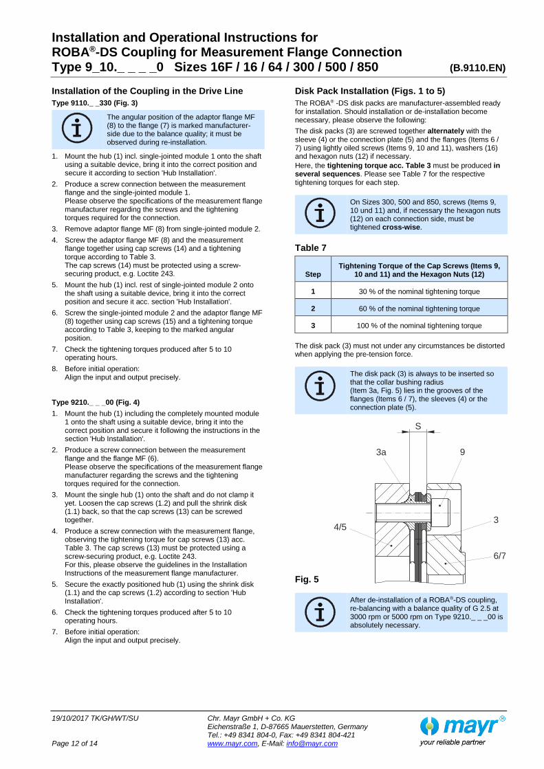
The angular position of the adaptor flange MF (8) to the flange (7) is marked manufacturer-side due to the balance quality; it must be observed during re-installation.
1. Mount the hub (2) onto the shaft, bring it into the correct position and secure it according to section 'Hub Installation'.
2. Produce a screw connection between the measurement flange and the hub (2). Please observe the specifications of the measurement flange manufacturer regarding the screws and the tightening torques required for the connection.
3. Remove adaptor flange MF (8) from module 2.
4. Screw the adaptor flange MF (8) and the measurement flange together using cap screws (14) and a tightening torque according to Table 3. The cap screws (14) must be protected using a screw-securing product, e.g. Loctite 243.
5. Mount the hub (1) including the rest of module 2 onto the shaft using a suitable device, bring it into the correct position and secure it according to section 'Hub Installation'.
6. Screw module 2 and the adaptor flange MF (8) together using cap screws (15) and a tightening torque according to Table 3, keeping to the marked angular position.
7. Check the tightening torques produced after 5 to 10 operating hours.
8. Before initial operation: Align the input and the output precisely.
Installation and Operational Instructions for ROBA®-DS Coupling for Measurement Flange Connection Type 9_10._ _ _ _0 Sizes 16F / 16 / 64 / 300 / 500 / 850 (B.9110.EN)
19/10/2017 TK/GH/WT/SU Chr. Mayr GmbH + Co. KG Eichenstraße 1, D-87665 Mauerstetten, Germany Tel.: +49 8341 804-0, Fax: +49 8341 804-421 Page 12 of 14 www.mayr.com, E-Mail: [email protected]
6/7
4/53
3a 9
S
Installation of the Coupling in the Drive Line
Type 9110._ _330 (Fig. 3)
The angular position of the adaptor flange MF (8) to the flange (7) is marked manufacturer-side due to the balance quality; it must be observed during re-installation.
1. Mount the hub (1) incl. single-jointed module 1 onto the shaft using a suitable device, bring it into the correct position and secure it according to section 'Hub Installation'.
2. Produce a screw connection between the measurement flange and the single-jointed module 1. Please observe the specifications of the measurement flange manufacturer regarding the screws and the tightening torques required for the connection.
3. Remove adaptor flange MF (8) from single-jointed module 2.
4. Screw the adaptor flange MF (8) and the measurement flange together using cap screws (14) and a tightening torque according to Table 3. The cap screws (14) must be protected using a screw-securing product, e.g. Loctite 243.
5. Mount the hub (1) incl. rest of single-jointed module 2 onto the shaft using a suitable device, bring it into the correct position and secure it acc. section 'Hub Installation'.
6. Screw the single-jointed module 2 and the adaptor flange MF (8) together using cap screws (15) and a tightening torque according to Table 3, keeping to the marked angular position.
7. Check the tightening torques produced after 5 to 10 operating hours.
8. Before initial operation: Align the input and output precisely.
Type 9210._ _ _00 (Fig. 4)
1. Mount the hub (1) including the completely mounted module 1 onto the shaft using a suitable device, bring it into the correct position and secure it following the instructions in the section 'Hub Installation'.
2. Produce a screw connection between the measurement flange and the flange MF (6). Please observe the specifications of the measurement flange manufacturer regarding the screws and the tightening torques required for the connection.
3. Mount the single hub (1) onto the shaft and do not clamp it yet. Loosen the cap screws (1.2) and pull the shrink disk (1.1) back, so that the cap screws (13) can be screwed together.
4. Produce a screw connection with the measurement flange, observing the tightening torque for cap screws (13) acc. Table 3. The cap screws (13) must be protected using a screw-securing product, e.g. Loctite 243. For this, please observe the guidelines in the Installation Instructions of the measurement flange manufacturer.
5. Secure the exactly positioned hub (1) using the shrink disk (1.1) and the cap screws (1.2) according to section 'Hub Installation'.
6. Check the tightening torques produced after 5 to 10 operating hours.
7. Before initial operation: Align the input and output precisely.
Disk Pack Installation (Figs. 1 to 5)
The ROBA® -DS disk packs are manufacturer-assembled ready for installation. Should installation or de-installation become necessary, please observe the following:
The disk packs (3) are screwed together alternately with the sleeve (4) or the connection plate (5) and the flanges (Items 6 / 7) using lightly oiled screws (Items 9, 10 and 11), washers (16) and hexagon nuts (12) if necessary.
Here, the tightening torque acc. Table 3 must be produced in several sequences. Please see Table 7 for the respective tightening torques for each step. On Sizes 300, 500 and 850, screws (Items 9,
10 und 11) and, if necessary the hexagon nuts (12) on each connection side, must be tightened cross-wise.
Table 7
Step Tightening Torque of the Cap Screws (Items 9,
10 and 11) and the Hexagon Nuts (12)
1 30 % of the nominal tightening torque
2 60 % of the nominal tightening torque
3 100 % of the nominal tightening torque
The disk pack (3) must not under any circumstances be distorted when applying the pre-tension force. The disk pack (3) is always to be inserted so
that the collar bushing radius (Item 3a, Fig. 5) lies in the grooves of the flanges (Items 6 / 7), the sleeves (4) or the connection plate (5).
Fig. 5 After de-installation of a ROBA®-DS coupling,
re-balancing with a balance quality of G 2.5 at 3000 rpm or 5000 rpm on Type 9210._ _ _00 is absolutely necessary.

Installation and Operational Instructions for ROBA®-DS Coupling for Measurement Flange Connection Type 9_10._ _ _ _0 Sizes 16F / 16 / 64 / 300 / 500 / 850 (B.9110.EN)
19/10/2017 TK/GH/WT/SU Chr. Mayr GmbH + Co. KG Eichenstraße 1, D-87665 Mauerstetten, Germany Tel.: +49 8341 804-0, Fax: +49 8341 804-421 Page 13 of 14 www.mayr.com, E-Mail: [email protected]
Coupling Alignment
Exact coupling alignment reduces the reaction forces and therefore increases the lifetime of the coupling and the shaft bearing. We recommend alignment of the coupling (of the shaft ends) using a dial gauge or laser. In order to prevent axial distortion of the disk packs, the dimension "S" (Fig. 5, acc. Tables 1 and 2) must be maintained with aligned angular and radial shaft misalignments.
Permitted Shaft Misalignments
The ROBA®-DS coupling compensates for angular, axial and radial shaft misalignments (Fig. 7) without losing its backlash-free function. However, the permitted shaft misalignments indicated in the Technical Data must not simultaneously reach their maximum value. If more than one kind of misalignment takes place simultaneously, they influence each other. This means that the permitted misalignment values are dependent on one another, see Fig. 6. The sum total of the actual misalignments in percent of the maximum value must not exceed 100 % (see Fig. 6 and the following example).
Fig. 6
Example:
ROBA®-DS Size 300, Type 9210.11100
Axial displacement occurrence ΔKa = 0.16 mm equals 40 % of the permitted maximum value ΔKa = 0.4 mm Angular misalignment occurrence in the disk pack ΔKw = 0.048° equals 30 % of the permitted maximum value ΔKw = 0.16°. => permitted radial misalignment ΔKr = 30 % of the maximum value ΔKr = 0.08 mm => ΔKr = 0.024 mm Axial Radial Angular displacement misalignment misalignment
Fig. 7 On standard design Type 9110._ _ _ _0 and for
speeds > 5000 rpm, a limitation of the misalignment to max. 30 % is necessary. This will ensure that the machine runs far more smoothly. The permitted misalignment values for Type 9210._ _ _00 stated in Table 2 are already the reduced values.
Maintenance
ROBA®-DS couplings are mainly maintenance-free.
The following maintenance and inspection intervals are to be maintained:
1.) Visual inspection, inspection of the installation parameters (misalignment and tightening torques) and the coupling running behaviour before initial operation.
2.) Visual inspection, torsional backlash, inspection of the misalignment and the tightening torques, coupling running behaviour after 1000 h, at the latest after 3 months.
3.) If no irregularities or wear are found during the second maintenance and inspection interval, further inspection intervals can, with unchanged operating parameters, take place after 4000 operating hours or after maximum 12 months.
In extreme coupling ambient or operating conditions, the maintenance and inspection intervals should be shortened.
Disposal
All steel components: Steel scrap (Code No. 160117)
20
30%
25%
75%
0%
50%
20
40%
40
30%
60
60
80
80
100
100
ΔK a
ΔK
w
2x Δ
K w
ΔK
r
Δ Kw [%] Angular misalignment
Δ Ka [%] Axial displacement
Δ K
r [%
] R
ad
ial m
isalig
nm
en
t

Installation and Operational Instructions for ROBA®-DS Coupling for Measurement Flange Connection Type 9_10._ _ _ _0 Sizes 16F / 16 / 64 / 300 / 500 / 850 (B.9110.EN)
19/10/2017 TK/GH/WT/SU Chr. Mayr GmbH + Co. KG Eichenstraße 1, D-87665 Mauerstetten, Germany Tel.: +49 8341 804-0, Fax: +49 8341 804-421 Page 14 of 14 www.mayr.com, E-Mail: [email protected]
Malfunctions / Breakdowns
Malfunction Possible Causes Solutions
Changes in running noise and / or vibration
occurrence
Incorrect alignment, incorrect installation
1) Set the system out of operation.
2) Find / resolve the cause of incorrect alignment.
3) Check the coupling for wear.
Loose connecting screws, minor fretting corrosion under the screw head and on the disk pack
1) Set the system out of operation.
2) Check the coupling parts and replace if damaged.
3) Tighten the connecting screws to the specified torque.
4) Check the alignment and correct if necessary.
Tensioning screws for axial securement of the hubs are loose
1) Set the system out of operation.
2) Check the coupling alignment.
3) Tighten the tensioning screws for axial securement of the hubs to the specified torque.
4) Check the coupling for wear.
Disk pack breakage
Disk pack breakage due to high load impacts /
overload
1) Set the system out of operation.
2) Dismantle the coupling and remove the remainders of the disk packs.
3) Check the coupling parts and replace if damaged.
4) Find the cause of overload and remove it.
Operating parameters are not appropriate for the coupling
performance
1) Set the system out of operation.
2) Check the operating parameters and select a suitable coupling (observe installation space).
3) Install a new coupling.
4) Check the alignment.
Incorrect operation of the system unit
1) Set the system out of operation.
2) Dismantle the coupling and remove the remainders of the disk packs.
3) Check the coupling parts and replace if damaged.
4) Train and advise operating personnel.
Disk packs / connecting screws cracks or breakage
Drive vibrations
1) Set the system out of operation.
2) Dismantle the coupling and remove the remainders of the disk packs.
3) Check the coupling parts and replace if damaged.
4) Check the alignment and correct if necessary.
5) Find the cause of vibration and remove it.
mayr ® will take no responsibility or guarantee for replacement parts and accessories which have not been delivered by mayr ®, or for damage resulting from the use of these products.