installation and operational instructions for roba-stop -m
TRANSCRIPT

Installation and operational instructions for ROBA-stop®-M Brake Type 891. _ _ _ . _ Sizes 2 – 500 (B.8.1.EN)
2/11/2015 TK/KE/GC/GF Chr. Mayr GmbH + Co. KG Eichenstraße 1, D-87665 Mauerstetten, Germany Tel.: +49 8341 804-0, Fax: +49 8341 804-421 Page 1 of 21 www.mayr.com, E-Mail: [email protected] your reliable partner
Please read these Operational Instructions carefully and follow them accordingly! Ignoring these Instructions may lead to malfunctions or to brake failure, resulting in damage to other parts.
These Installation and Operational Instructions (I + O) are part of the brake delivery. Please keep them handy and near to the brake at all times.
Contents:
Page 1: - Contents
Page 2: - Guidelines on EU Directives
- Safety and Guideline Signs
Page 3: - Safety Regulations
Page 4: - Safety Regulations
Page 5: - Safety Regulations
Page 6: - Definition braking torques
- Run-in Procedure
Page 7: - Brake Illustrations
- Parts List
- Technical Data
Page 8: - Table 1: Technical Data (Dependent on Size)
- Table 2: Technical Data (Dependent on Size)
- Table 3: Technical Data (Dependent on Size)
Page 9: - Table 4: Technical Data (Dependent on Size)
- Table 5: Technical Data (Dependent on Size)
Page 10: - Table 6: Technical Data (Dependent on Size)
- Table 7: Technical Data (Dependent on Size)
- Design
- Function
- Scope of Delivery / State of Delivery
Page 11: - Installation Conditions
- Run-in Procedure
- Installation
Page 12: - Braking Torque Adjustment
- Brake Inspection
- Hand Release Installation
Page 13: - Switching Times
- Torque-Time Diagram
- Table 8: Switching Times (Dependent on Size)
Page 14: - Electrical Connection and Wiring
Page 15: - Electrical Connection and Wiring
Page 16: - Permitted Friction Work
- Friction Power Diagrams for Types 891.01_._ and 891. 21_._
Page 17: - Friction Power Diagrams for Type 891.10_._
Page 18: - Air Gap Inspection
- Maintenance
Page 19: - Disposal
Page 20: - Malfunctions / Breakdowns
Page 21: - Malfunctions / Breakdowns

Installation and operational instructions for ROBA-stop®-M Brake Type 891. _ _ _ . _ Sizes 2 – 500 (B.8.1.EN)
2/11/2015 TK/KE/GC/GF Chr. Mayr GmbH + Co. KG Eichenstraße 1, D-87665 Mauerstetten, Germany Tel.: +49 8341 804-0, Fax: +49 8341 804-421 Page 2 of 21 www.mayr.com, E-Mail: [email protected] your reliable partner
Safety and Guideline Signs
DANGER
Immediate and impending danger which can lead to severe physical injuries or to death.
WARNING
Possibly dangerous situation, which can lead to severe physical injuries or to death.
CAUTION
Danger of injury to personnel and damage to machines.
Please Observe! Guidelines on important points.
Guidelines on the Declaration of Conformity
A conformity evaluation has been carried out for the product (electromagnetic safety brake) in terms of the EC Low Volt-age Directive 2006/95/EC. The Declaration of Conformity is laid out in writing in a separate document and can be re-quested if required.
Guidelines on the EMC Directive (2004/108/EC) The product cannot be operated independently according to the EMC directive. Due to their passive state, brakes are also non-critical equipment according to the EMC. Only after integration of the product into an overall system can this be evaluated in terms of the EMC. For electronic equipment, the evaluation has been verified for the individual product in laboratory conditions, but not in the overall system.
Guidelines on the Machinery Directive (2006/42/EC) The product is a component for installation into machines according to the machinery directive 2006/42/EC. The brakes can fulfil the specifications for safety-related applications in coordination with other elements. The type and scope of the required measures result from the machine risk analysis. The brake then becomes a machine component and the machine manufacturer assesses the conformity of the safety device to the directive. It is forbidden to start use of the product until you have ensured that the machine accords with the regulations stated in the directive.
Guidelines on the EU Directive on the Restriction of the Use of Certain Hazardous Substances in Electrical and Electronic Equipment The electromagnetic brake as well as the rectifiers / microswitches / proximity switches required for control / self-monitor-ing fulfil the requirements laid down in the EU Directive 2011/65/EC (RoHS). (Restrictions on the use of certain hazardous substances, such as lead (0.1 %), mercury (0.1 %), cadmium (0.01 %), hex-avelent chromium (0.1 %), polybrominated biphenyls (PBB) (0.1 %), polybrominated diphenylethers (PBDE) (0.1 %))
Guidelines on the ATEX Directive Without a conformity evaluation, this product is not suitable for use in areas where there is a high danger of explosion. For application of this product in areas where there is a high danger of explosion, it must be classified and marked accord-ing to directive 94/9/EC.

Installation and operational instructions for ROBA-stop®-M Brake Type 891. _ _ _ . _ Sizes 2 – 500 (B.8.1.EN)
2/11/2015 TK/KE/GC/GF Chr. Mayr GmbH + Co. KG Eichenstraße 1, D-87665 Mauerstetten, Germany Tel.: +49 8341 804-0, Fax: +49 8341 804-421 Page 3 of 21 www.mayr.com, E-Mail: [email protected] your reliable partner
Safety Regulations These Safety Regulations are user hints only and may not be complete!
General Guidelines
DANGER
Danger of death! Do not touch voltage-carrying lines and components.
Brakes may generate further risks, among other things:
Hand injuries
Danger of sei-zure
Contact with hot surfaces
Magnetic fields
Severe injury to people and damage to objects may result if:
the electromagnetic brake is used incorrectly.
the electromagnetic brake is modified.
the relevant standards for safety and / or installation condi-tions are ignored.
During the risk assessment required when designing the machine or system, the dangers involved must be evaluated and removed by taking appropriate protective measures.
To prevent injury or damage, only professionals and spe-cialists are allowed to work on the devices. They must be fa-miliar with the dimensioning, transport, installation, initial opera-tion, maintenance and disposal according to the relevant stand-ards and regulations.
Before product installation and initial operation, please read the Installation and Operational In-structions carefully and observe the Safety Regulations. Incorrect operation can cause in-jury or damage.
At the time these Installation and Operational Instructions go to print, the electromagnetic brakes accord with the known technical specifications and are operationally safe at the time of delivery.
Technical data and specifications (Type tags and documen-tation) must be followed.
The correct connection voltage must be connected accord-ing to the Type tag and wiring guidelines.
Check electrical components for signs of damage before putting them into operation. Never bring them into contact with water or other fluids.
Please observe the EN 60204-1 requirements for electrical connection when using in machines.
Only carry out installation, maintenance and repairs in a de-energised, disengaged state and secure the system against inadvertent switch-on.
Guidelines for Electromagnetic Compatibility (EMC)
In accordance with the EMC directives 2004/108/EC, the individ-ual components produce no emissions. However, functional components e.g. mains-side energisation of the brakes with rec-tifiers, phase demodulators, ROBA®-switch devices or similar controls can produce disturbance which lies above the allowed
limit values. For this reason it is important to read the Installation and Opera-tional Instructions very carefully and to keep to the EMC Direc-tives.
Application Conditions
The catalogue values are guideline values which have been determined in test facilities. It may be necessary to carry out your own tests for the intended application. When dimension-ing the brakes, please remember that installa-
tion situations, braking torque fluctuations, permitted friction work, run-in behaviour and wear as well as general ambient conditions can all affect the given values. These factors should therefore be carefully assessed, and alignments made accordingly.
Mounting dimensions and connection dimensions must be adjusted according to the size of the brake at the place of installation.
The magnetic coils are designed for a relative duty cycle of 100%.
The braking torque is dependent on the present run-in con-dition of the brake.
The brakes are only designed for dry running. The torque is lost if the friction surfaces come into contact with oil, grease, water or similar substances or foreign bodies.
The surfaces of the outer components have been phos-phated manufacturer-side to form a basic corrosion protec-tion.
CAUTION The rotors may rust up and block in corrosive ambient conditions and/or after long periods of storage. The user is responsible for taking appropriate countermeasures.
Dimensioning
Attention! When dimensioning the brake, please take into consideration whether a load torque is present when selecting the protection. Load torques reduce the deceleration torque available. Load torques may increase the output speed:
during a possible processing time in the controls during the brake downtime
When calculating the friction work, please observe that the brake nominal torque is subject to a tolerance.

Installation and operational instructions for ROBA-stop®-M Brake Type 891. _ _ _ . _ Sizes 2 – 500 (B.8.1.EN)
2/11/2015 TK/KE/GC/GF Chr. Mayr GmbH + Co. KG Eichenstraße 1, D-87665 Mauerstetten, Germany Tel.: +49 8341 804-0, Fax: +49 8341 804-421 Page 4 of 21 www.mayr.com, E-Mail: [email protected] your reliable partner
Safety Regulations These Safety Regulations are user hints only and may not be complete!
Climate Conditions
The ROBA-stop®-M is suitable for applications with an ambient temperature of between -20 °C and +40 °C.
CAUTION Reduction in braking torque possible Condensation can form on the brake and cause a loss in braking torque: due to fast changes in temperature at temperatures of around or under
freezing point The user is responsible for taking appropriate countermeasures (e.g. forced convection, heating, drain screw).
CAUTION Brake malfunction possible Condensation can form on the brake and cause malfunctions: at temperatures around or under freezing
point, the brake can freeze over and not release any more.
The user is responsible for taking appropriate countermeasures (e.g. forced convection, heating, drain screw).
The system function must be checked by the user after longer downtimes. at high temperatures and in high humidity or with occurring
dampness, the rotor can seize up to the armature disk or the bearing shield / the flange plate after longer downtimes.
Intended Use
mayr ®-brakes have been developed, manufactured and tested in compliance with the DIN VDE 0580 standard and in accord-ance with the EU Low Voltage Directive as electromagnetic com-ponents. During installation, operation and maintenance of the product, the requirements for the standard must be observed. mayr®-brakes are for use in machines and systems and must only be used in the situations for which they are ordered and confirmed. Using them for any other purpose is not allowed.
Earthing Connection
The brake is designed for Protection Class I. This protection co-vers not only the basic insulation, but also the connection of all conductive parts to the protective conductor (PE) on the fixed in-stallation. If the basic insulation fails, no contact voltage will re-main. Please carry out a standardised inspection of the protec-tive conductor connections to all contactable metal parts!
Class of Insulation F (+155 °C)
The insulation components on the magnetic coils are manufac-tured at least to class of insulation F (+155 °C).
Protection
(mechanical) IP54 for Types 891._ _ _ .0/2/3: When installed, dust-proof and protected against contact as well as against water spray from any direction (dependent on cus-tomer-side mounting method).
(mechanical) IP65 for Types 891._ _ _ .1: When installed, dust-proof and protected against contact as well as against jet water from a nozzle coming from any direction (de-pendent on customer-side mounting method).
(electrical) IP54: Dust-proof and protected against contact as well as against water spray from any direction.
Brake Storage
Store the brakes in a horizontal position, in dry rooms and dust and vibration-free.
Relative air humidity < 50 %.
Temperature without major fluctuations within a range from –20 °C up to +60 °C.
Do not store in direct sunlight or UV light.
Do not store aggressive, corrosive substances (solvents / acids / lyes / salts / oils / etc.) near to the brakes.
For longer storage of more than 2 years, special measures are required (please contact the manufacturer). Storage acc. DIN EN 60721-3-1 (including the limitations / addi-tions described above): 1K3; 1Z1; 1B1; 1C2; 1S3; 1M1
Handling
Before installation, the brake must be inspected and found to be in proper condition. The brake function must be inspected both once attachment has taken place as well as after longer system downtimes, in order to prevent the drive starting up against possibly seized lin-ings.
User-implemented Protective Measures:
Please cover moving parts to protect against injury through seizure.
Place a cover on the magnetic part to protect against in-jury through high temperatures.
Protection circuit: When using DC-side switching, the coil must be protected by a suitable protection circuit according to VDE 0580, which is integrated in mayr®-rectifiers. To protect the switching contact from consumption when using DC-side switching, additional protective measures may be necessary (e.g. series connection of switching contacts). The switching contacts used should have a minimum con-tact opening of 3 mm and should be suitable for inductive load switching. Please make sure on selection that the rated voltage and the rated operating current are sufficient. Depending on the application, the switching contact can also be protected by other protection circuits (e.g. mayr ®-spark quenching unit, half-wave and bridge rectifiers), alt-hough this may of course then alter the switching times.
Install additional protective measures against corrosion if the brake is subject to extreme ambient conditions or is in-stalled in open air conditions, unprotected from the weather.
Take precautions against freeze-up of the friction sur-faces in high humidity and at low temperatures.

Installation and operational instructions for ROBA-stop®-M Brake Type 891. _ _ _ . _ Sizes 2 – 500 (B.8.1.EN)
2/11/2015 TK/KE/GC/GF Chr. Mayr GmbH + Co. KG Eichenstraße 1, D-87665 Mauerstetten, Germany Tel.: +49 8341 804-0, Fax: +49 8341 804-421 Page 5 of 21 www.mayr.com, E-Mail: [email protected] your reliable partner
Safety Regulations These Safety Regulations are user hints only and may not be complete!
Standards, Directives and Regulations Used
DIN VDE 0580 Electromagnetic devices and compo-nents, general specifications
2006/95/EC Low Voltage Directive
CSA C22.2 No. 14-2010 Industrial Control Equipment
UL 508 (Edition 17) Industrial Control Equipment
EN ISO 12100 Safety of machinery – General princi-ples for design - Risk assessment and risk reduction
DIN EN 61000-6-4 Interference emission
DIN EN 61000-6-2 Interference immunity
Liability
The information, guidelines and technical data in these documents were up to date at the time of printing. Demands on previously delivered brakes are not valid. Liability for damage and operational malfunctions will not be taken if:
- the Installation and Operational Instructions are ignored or ne-glected.
- the brakes are used inappropriately.
- the brakes are modified.
- the brakes are worked on unprofessionally.
- the brakes are handled or operated incorrectly.
Guarantee
The guarantee conditions correspond with the Chr. Mayr GmbH + Co. KG sales and delivery conditions.
Mistakes or deficiencies are to be reported to mayr ® at once!
CE Identification
according to the Low Voltage Directive 2006/95/EC
Conformity Markings
in terms of the Canadian and American approval
Identification
mayr® components are clearly marked and described on the Type tag:
Product name Serial number Article number Approval number (if available)
CE marking Size/Type Voltage Power Braking torque DataMatrix code only for voltages > 72V (CE identification with ID number of the respective inspection authority, only for type examination tested brakes)
®
C US

Installation and operational instructions for ROBA-stop®-M Brake Type 891. _ _ _ . _ Sizes 2 – 500 (B.8.1.EN)
2/11/2015 TK/KE/GC/GF Chr. Mayr GmbH + Co. KG Eichenstraße 1, D-87665 Mauerstetten, Germany Tel.: +49 8341 804-0, Fax: +49 8341 804-421 Page 6 of 21 www.mayr.com, E-Mail: [email protected] your reliable partner
Safety-relevant Applications
Brakes which are used in safety-related applications are to be selected in accordance with the risk assessment EN ISO 12100 and furthermore in accordance with EN ISO 13849-1 through identification of the safety function.
This is in principle the task of the system manufacturer.
Roba-stop®-M standard designs with safety parameters:
Type 891.10_._ Nominal torque holding brake
Type 891.01_._ 100% nominal torque standard
Type 891.02_._ 84% nominal torque
Type 891.02_._ 68% nominal torque
Type 891.01_._ 112% nominal torque standard
Type 891.01_._ 125% nominal torque standard
Safety parameters can be requested if required. In case of deviating designs, please consult with mayr® power transmission directly.
Definition of the Braking Torques
Static braking torque
Effectively averaged, fully developed torque at slipping brake with smallest speed values. Guideline value: n = 3 [1/min]
Dynamic braking torque
Effectively averaged, fully developed torque in a braking procedure from the output speed up to standstill.
For correct evaluation, a sufficient slip time is required (sliding speed between 1 m/s and 10 m/s).
The permitted friction work and speed values must not be exceeded.
Run-in procedure / Conditioning of the friction lining pairing
The stated brake nominal torques are valid for a run-in / conditioned state of the friction lining pairing in standard climate conditions.
Conditioning of the friction lining pairing
Conditioning is necessary in new condition
during the operation of the system
Please carry out condition-ing of the friction lining pairing through dynamic braking procedures of the system.
Recommendation:
Approx. Please carry out approx. 5 dynamic braking procedures
at 50 % of the permitted speed nmax
at 25 % of the permitted friction work Qr zul.
A generally valid definition of the parameters required for the conditioning is not possible due to the different
application possibilities.
The frequency of the friction lining pairing conditioning and the torque inspection must be determined by the user depending on the application.
Regular conditioning is not possible
Dimension with a correspondingly higher safety
Recommendation: Si ≥ 2.0
Please observe: The dynamic dimensioning must be taken into account separately
EMERGENCY STOP After brake run-in procedure!
Installation and operational instructions for ROBA-stop®-M Brake Type 891. _ _ _ . _ Sizes 2 – 500 (B.8.1.EN)
2/11/2015 TK/KE/GC/GF Chr. Mayr GmbH + Co. KG Eichenstraße 1, D-87665 Mauerstetten, Germany Tel.: +49 8341 804-0, Fax: +49 8341 804-421 Page 7 of 21 www.mayr.com, E-Mail: [email protected] your reliable partner
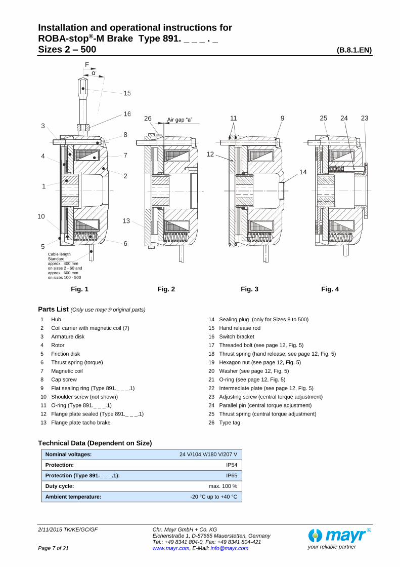
Fig. 1 Fig. 2 Fig. 3 Fig. 4
Parts List (Only use mayr original parts)
1 Hub 14 Sealing plug (only for Sizes 8 to 500)
2 Coil carrier with magnetic coil (7) 15 Hand release rod
3 Armature disk 16 Switch bracket
4 Rotor 17 Threaded bolt (see page 12, Fig. 5)
5 Friction disk 18 Thrust spring (hand release; see page 12, Fig. 5)
6 Thrust spring (torque) 19 Hexagon nut (see page 12, Fig. 5)
7 Magnetic coil 20 Washer (see page 12, Fig. 5)
8 Cap screw 21 O-ring (see page 12, Fig. 5)
9 Flat sealing ring (Type 891._ _ _.1) 22 Intermediate plate (see page 12, Fig. 5)
10 Shoulder screw (not shown) 23 Adjusting screw (central torque adjustment)
11 O-ring (Type 891._ _ _.1) 24 Parallel pin (central torque adjustment)
12 Flange plate sealed (Type 891._ _ _.1) 25 Thrust spring (central torque adjustment)
13 Flange plate tacho brake 26 Type tag
Technical Data (Dependent on Size)
Nominal voltages: 24 V/104 V/180 V/207 V
Protection: IP54
Protection (Type 891._ _ _.1): IP65
Duty cycle: max. 100 %
Ambient temperature: -20 °C up to +40 °C
232425
12
11 9
14
Cable length Standard approx.. 400 mm on sizes 2 - 60 and approx.. 600 mm on sizes 100 - 500
Air gap “a”
13
26
5
10
1
4
3
15
16
8
7
2
6
F
α

Installation and operational instructions for ROBA-stop®-M Brake Type 891. _ _ _ . _ Sizes 2 – 500 (B.8.1.EN)
2/11/2015 TK/KE/GC/GF Chr. Mayr GmbH + Co. KG Eichenstraße 1, D-87665 Mauerstetten, Germany Tel.: +49 8341 804-0, Fax: +49 8341 804-421 Page 8 of 21 www.mayr.com, E-Mail: [email protected] your reliable partner
Table 1: Technical Data (Dependent on Size)
Size
Nominal torque Standard brake
Type 891._ 1 _ . _ M2
[Nm]
Nominal torque Holding brake
Type 891.10 _ . _ M2
[Nm]
Max. Speed
nmax
[rpm]
PN Electrical
nominal power
[W]
Electrical Connection
cross-section
[mm2]
Mass without flange plate, without hand release
[kg]
2 2 4 6000 19 2 x 0.56 0.76
4 4 8 5000 25 2 x 0.56 1.1
8 8 16 4000 29 2 x 0.56 1.8
16 16 32 3500 38 2 x 0.88 3.4
32 32 64 3000 46 2 x 0.88 4.5
60 60 100 3000 69 2 x 0.88 7.4
100 100 180 3000 88 2 x 0.88 13.6
150 150 250 1500 98 2 x 0.88 19.2
250 250 450 1500 120 2 x 0.88 33.3
500 500 800 1) 1500 152 2 x 0.88 38
1) Brake operation from 700 Nm only possible with overexcitation.
Table 2: Technical data (dependent on size)
Size
Nominal air gap "a"
+0.1 / -0.05
Maximum permitted air gap "a" after
wear
Inspec-tion di-
mension "x"
Numberof turns "Y" on the hex-agon nuts (19)
Fixing screw Item 8 (Fig. 1)
Design with-out flange
plate
Design with flange plate
Tighten-ing
torque
(Fig. 2) (Fig. 2) (Fig. 5) (Fig. 5) (Item 12/13) (Item 12/13)
[mm] [mm] [mm] DIN DIN [Nm]
2 0.15 0.4 0.9 +0.1 1.7 3 x M4 x 45 6912 3 x M4 x 50 EN ISO
4762 2.5
4 0.15 0.4 0.9 +0.1 1.7 3 x M4 x 45 6912 3 x M4 x 50 EN ISO
4762 2.5
8 0.2 0.45 1.1 +0.1 1.5 3 x M5 x 50 6912 3 x M5 x 55 6912 5.0
16 0.2 0.7 1.6 +0.1 2.0 3 x M6 x 60 6912 3 x M6 x 65 6912 9.0
32 0.2 0.7 1.8 +0.1 2.0 3 x M6 x 60 6912 3 x M6 x 70 EN ISO
4762 9.0
60 0.25 0.8 2.2 +0.1 2.0 3 x M8 x 75 6912 3 x M8 x 85 EN ISO
4762 22
100 0.3 0.9 2.2 +0.1 1.6 3 x M8 x 80 EN ISO
4762 3 x M8 x 90
EN ISO 4762
22
150 0.3 0.9 2.2 +0.1 1.6 3 x M8 x 100 EN ISO
4762 3 x M8 x 110
EN ISO 4762
22
250 0.35 0.95 2.4 +0.1 1.5 3 x M10 x 110 EN ISO
4762 3 x M10 x 130
EN ISO 4762
45
500 0.4 +0.2 1.0 2.4 +0.1 1.5 6 x M10 x 110 EN ISO
4762 6 x M10 x 130
EN ISO 4762
45
Table 3: Technical data (dependent on size)
Hand release force [N] at
Release an-gle
""
Min. width of the counter friction
surface
Tightening torque shoulder
screw Item 10 (Fig. 1)
Through hole (coil carrier back)
[mm]
Size Type 891.0/2
Type 891.1
[°]
[mm] [Nm] Type 891._ _ _.0
Type 891._ _ _.1
Type 891._ _ _.2
2 20 26 6 5 0.5 16.5 Brake closed 23.5 H7
4 35 45 7 6 0.5 18 Brake closed 28.5 H7
8 70 90 7 6 1.5 22 22 H8 32.5 H7
16 100 125 7 7 2.0 33 22 H8 40.5 H7
32 130 170 8 8 2.0 36 28 H8 52.5 H7
60 220 300 10 8 3.5 38 32 H8 60 H7
100 260 340 12 10 8.0 48 42 H8 75.5 H7
150 290 350 13 12 8.0 55 48 H8 82.5 H7
250 350 430 10 14 18.5 65 52 H8 92 H7
500 310 470 10 19 18.5 85 62 H8 131 H7

Installation and operational instructions for ROBA-stop®-M Brake Type 891. _ _ _ . _ Sizes 2 – 500 (B.8.1.EN)
2/11/2015 TK/KE/GC/GF Chr. Mayr GmbH + Co. KG Eichenstraße 1, D-87665 Mauerstetten, Germany Tel.: +49 8341 804-0, Fax: +49 8341 804-421 Page 9 of 21 www.mayr.com, E-Mail: [email protected] your reliable partner
Table 4: Technical data (dependent on size)
Valid for standard brakes type 891.0_ _._ and 891.2_ _._
Size
Mass moment of inertia J Hub + rotor on dmax [kgm2]
Friction work Qr 0.1 (per 0.1 mm wear)
[J]
Friction work Qr ges. (max. possible friction work related to nominal air gap)
[J]
Rotor thickness
“new”
[mm]
Minimum rotor thick-ness
(limit value for braking torque 100 %)
[mm]
Type 891.0_ _._
Type 891.2_ _._
2 0.12 x 10 -4 0.1 x 10 -4 35 x 10 6 95 x 10 6 6.05 5.8
4 0.21 x 10 -4 0.17 x 10 -4 40 x 10 6 100 x 10 6 6.05 5.8
8 0.67 x 10 -4 0.58 x 10 -4 65 x 10 6 162 x 10 6 6.9 6.65
16 1.74 x 10 -4 1.53 x 10 -4 100 x 10 6 500 x 10 6 8.0 7.5
32 4.48 x 10 -4 4.1 x 10 -4 130 x 10 6 600 x 10 6 10.4 9.9
60 6.74 x 10 -4 – 130 x 10 6 700 x 10 6 11.15 10.6
100 16.54 x 10 -4 – 140 x 10 6 840 x 10 6 14.0 13.4
150 31.68 x 10 -4 – 150 x 10 6 950 x 10 6 15.5 14.9
250 61.82 x 10 -4 – 160 x 10 6 1000 x 10 6 17 16.4
500 222.6 x 10 -4 – 200 x 10 6 1200 x 10 6 18.5 17.9
The stated values Qr 0.1 and Qr ges. are only reference values for specific friction work values < 0.5 J/mm2 and sliding speeds < 10 m/s.
Table 5: Technical data (dependent on size)
Valid for holding brakes Type 891.1_ _._
Size
Mass moment of inertia J Hub + rotor on dmax
[kgm2]
Friction work Qr 0.1 (per 0.1 mm wear)
[J]
Friction work Qr ges. (max. possible friction work related to nominal air gap)
[J]
Rotor thickness “new”
[mm]
2 0.12 x 10 -4 7 x 10 6 7 x 10 6 6.05
4 0.21 x 10 -4 8 x 10 6 8 x 10 6 6.05
8 0.67 x 10 -4 13 x 10 6 13 x 10 6 6.9
16 1.74 x 10 -4 20 x 10 6 20 x 10 6 8.0
32 4.48 x 10 -4 30 x 10 6 45 x 10 6 10.4
60 6.74 x 10 -4 65 x 10 6 130 x 10 6 11.15
100 16.54 x 10 -4 70 x 10 6 170 x 10 6 14.0
150 31.68 x 10 -4 75 x 10 6 300 x 10 6 15.5
250 61.82 x 10 -4 80 x 10 6 350 x 10 6 17
500 222.6 x 10 -4 85 x 10 6 500 x 10 6 18.5
The stated values Qr 0.1 and Qr ges. are only reference values for specific friction work values < 0.5 J/mm2 and sliding speeds < 10 m/s.

Installation and operational instructions for ROBA-stop®-M Brake Type 891. _ _ _ . _ Sizes 2 – 500 (B.8.1.EN)
2/11/2015 TK/KE/GC/GF Chr. Mayr GmbH + Co. KG Eichenstraße 1, D-87665 Mauerstetten, Germany Tel.: +49 8341 804-0, Fax: +49 8341 804-421 Page 10 of 21 www.mayr.com, E-Mail: [email protected] your reliable partner
Table 6: Technical Data (Dependent on Size)
Size
Permitted hub bores for standard brake Type 891.0_ _._ und 891.2_ _._
Permitted hub bores for holding brake Type 891.10 _._
Keyway – JS9 Keyway – P9 Keyway – JS9 Keyway – P9
DIN 6885/1 DIN 6885/3 DIN 6885/1 DIN 6885/3 DIN 6885/1 DIN 6885/3 DIN 6885/1 DIN 6885/3
2 8 – 13 13 – 15 8 – 13 13 – 15 8 – 13 13 – 15 8 – 13 13 – 15
4 10 – 13 13 – 15 10 – 13 13 – 15 10 – 13 13 – 15 10 – 13 13 – 15
8 11 – 18 18 – 20 11 – 18 18 – 20 11 – 18 18 – 20 11 – 18 18 – 20
16 14 – 22 22 – 25 14 – 20 20 – 22 14 – 22 22 – 25 14 – 20 20 – 22
32 19 – 30 – 19 – 28 28 – 30 19 – 30 – 19 – 28 28 – 30
60 22 – 32 32 – 35 22 – 32 – 22 – 32 32 – 35 22 – 32 –
100 24 – 42 42 – 45 24 – 42 42 – 45 24 – 42 42 – 45 24 – 42 42 – 45
150 30 – 45 45 – 50 30 – 45 45 – 50 30 – 45 45 – 50 30 – 45 45 – 50
250 40 2) – 55 55 – 60 40 2) – 50 50 – 55 40 – 55 – 40 – 50 50 – 55
500 50 2) – 75 75 – 80 50 2) – 75 75 – 80 50 – 75 – 50 – 75 –
2) Minimum bore not permitted for braking torque adjustment = 125 %.
Table 7: Technical data (dependent on size)
Braking torque [Nm] with tolerance
+40 % / -20 % 4)
Size
125 % Type
891._8_._
112 % Type
891._7_._
Standard brake 100 % Type
891._1_._
84 % Type
891._2_._
68 % Type
891._3_._
50 % Type
891._4_._
34 % Type
891._5_._
Holding brake Type
891.10_._
2 2.5 2.2 2 1.7 1.4 1 0.7 4
4 5 4.5 4 3.4 2.8 2 1.4 8
8 10 9 8 6.8 5.5 4 2.8 16
16 20 18 16 13.5 11 8 5.5 32
32 40 36 32 27 22 16 11 64
60 75 68 60 51 42 30 21 100
100 125 110 100 85 70 50 180
150 185 165 150 125 100 75 250
250 312 280 250 215 180 125 450
500 700 3) 600 500 400 350 250 200 800 5)
3) Brake operation as holding brake. 4) For restricted braking torque tolerances please contact mayr® power transmission. 5) Brake operation from 700 Nm only possible with overexcitation.
1. Design
ROBA-stop®-M brakes are spring applied, electromagnetic safety brakes, which apply a defined braking effect after the voltage is switched off or after a voltage failure.
2. Function
The ROBA-stop®-M brake is a spring applied, electromagnetic safety brake. Spring applied function (brake): In de-energised condition, thrust springs (6) press against the ar-mature disk (3). The rotor (4) is held between the armature disk (3) and the friction disk (5), the flange plate (12 or 13 / depend-ent on Type) or the customer-side machine wall via frictional locking. The braking torque is introduced into the drive line via the tooth-ing of the rotor (4) and the hub (1). Electromagnetic function (release): Due to the magnetic force of the coil in the coil carrier (2), the ar-mature disk (3) is attracted against the spring pressure to the coil carrier (2). The brake is released and the brake rotor (4) with the hub (1) can rotate freely.
Safety brakes: The ROBA-stop®-M brake brakes reliably and safely in the event of a power switch-off, a power failure or an EMERGENCY STOP.
3. Scope of Delivery / State of Delivery
Please check the scope of delivery as well as the state of deliv-ery immediately after receiving the goods. mayr ® will take no responsibility for belated complaints. Please report transport damage immediately to the deliverer. Please report incomplete delivery and obvious defects immedi-ately to the manufacturer.

Installation and operational instructions for ROBA-stop®-M Brake Type 891. _ _ _ . _ Sizes 2 – 500 (B.8.1.EN)
2/11/2015 TK/KE/GC/GF Chr. Mayr GmbH + Co. KG Eichenstraße 1, D-87665 Mauerstetten, Germany Tel.: +49 8341 804-0, Fax: +49 8341 804-421 Page 11 of 21 www.mayr.com, E-Mail: [email protected] your reliable partner
4. Installation Conditions
The eccentricity of the shaft end in relation to the mounting pitch circle must not exceed 0.2 mm.
The positional tolerance of the threads for the cap screws (8) must not exceed 0.2 mm.
The axial run-out deviation of the screw-on surface to the shaft must not exceed the permitted axial run-out tolerance of 0.08 mm for Sizes 2 to 8, of 0.1 mm for Sizes 16 to 250, and of 0.125 mm for Size 500, according to DIN 42955. The reference diameter is the pitch circle diameter for se-curement of the brakes. Larger deviations can lead to a drop in torque, to continu-ous grinding of the rotor (4) and to overheating.
The tolerances of the hub bore (1) and the shaft must be selected so that the hub toothing (1) is not widened. Widen-ing of the toothing leads to the rotor (4) jamming on the hub (1) and therefore to brake malfunctions. Recommended hub – shaft tolerance H7/k6. The max. permitted joining temperature of 200 °C must not be exceeded.
The rotor (4) and brake surfaces must be oil and grease-free.
A suitable counter friction surface (steel or cast iron) must be used. Sharp-edged interruptions on the friction surfaces must be avoided.
For holding brakes: (Task: Holding application with EMERGENCY STOP function)
Surface quality in the fric-tion area of the friction surface between Ra = 1.6 µm up to Ra = 3.2 µm
For dynamic applica-tions: (Task: Frequent dynamic braking)
Surface quality in the fric-tion area of the friction surface Ra = 1.6 µm.
Attention!
When machining grey cast iron, please make sure that the cast tips are removed.
The toothings of the hub (1) and the rotor (3) must not be
oiled or greased.
Friction value-increasing surface treatments are not permit-ted.
Dimensioning of the key connection according to the re-quirements shaft diameter, transmittable torque and operat-ing conditions must be carried out. For this, the correspond-ing user data must be known or the customer must carry out the dimensioning according to the valid calculation ba-sis DIN 6892. For the calculation, a hub quality of Re = 230 N/mm2 should be used for Sizes 2 and 4 and of Re = 300 N/mm2 should be used for Sizes 8 to 500. The length of the key should lie over the entire hub.
For the dimensioning of the key connections, the permitted tensions common in machine construction must be consid-ered. During initial operation, check whether the key is in-serted correctly and whether the brake is secured to the correct tightening torque acc. Table 2.
Please abstain from using cleaning agents containing sol-vents, as they could affect the friction material.
Protect the rotor from rusting up / seizing up against the bearing shield / the flange plate (customer-side). We recommend tried and tested anti-corrosion measures for the mounting surface:
dry, oil-free phosphate layers
Hard chromium and nitriding
Run-in Procedure
Please carry out conditioning of the friction lining pairing before initial operation of the system (see “Run-in procedure / Condi-tioning of the friction lining pairing”, page 6)
5. Installation (Figs. 1 and 2)
5.1. Mount the hub (1) onto the shaft, bring it into the correct position and secure it axially (e.g. using a locking ring).
5.2. If necessary (dependent on Type), insert the O-ring (11) into the axial groove of the flange plate (12).
5.3. If necessary (dependent on Type), guide the friction disk (5) or flange plate (12/13) over the shaft and attach it to the machine wall (observe the bore alignments in the friction disk (5) or flange plate (12/13) to the threaded bores in the machine wall).
In the delivery of Sizes 150 and 250, three ad-ditional (shorter) cap screws are included in addition to the fixing screws (8). These additional screws must only be used for attaching the flange plate (12/13) by the cus-tomer, when personal protection acc. to the B 10d value is required. For this, 3 stepped bores can be found in the flange plates. Tight-ening torque like Item 8 of the respective Size acc. Table 3.
5.4. Measure the rotor thickness and compare with the values in Tables 4/5. Push the rotor (4) onto the hub (1) by hand (the rotor collar should be facing away from the machine wall or friction disk (5) or flange plate (12/13)). The rotor toothing must lie over the entire length of the hub (1). Check that the toothing moves easily. Do not cause any damage!
5.5. If necessary, install the hand release acc. section 8 on page 12.
5.6. If necessary (dependent on Type), insert the O-ring (11) into the axial groove of the coil carrier (2).
5.7. Push the rest of the brake over the hub (1) and the rotor collar (4) (the fixing holes should align with the bores on the friction disk (5), the flange plate (12/13) or the machine wall). The shoulder screws (10) prevent the individual compo-nents from falling apart. They do not affect the brake function and must not be re-moved during installation.
5.8. Secure the brake evenly all around using the cap screws (8) inc. the manufacturer-side mounted flat sealing rings (9 / dependent on Type) with a torque wrench and a tight-ening torque (acc. Table 2).

Installation and operational instructions for ROBA-stop®-M Brake Type 891. _ _ _ . _ Sizes 2 – 500 (B.8.1.EN)
2/11/2015 TK/KE/GC/GF Chr. Mayr GmbH + Co. KG Eichenstraße 1, D-87665 Mauerstetten, Germany Tel.: +49 8341 804-0, Fax: +49 8341 804-421 Page 12 of 21 www.mayr.com, E-Mail: [email protected] your reliable partner
6. Braking Torque Adjustment
The ROBA-stop®-M brakes are set manufacturer-side to the braking torque stipulated on order. Different braking torque adjustments can be made using different spring configurations (6) in the coil carrier (2) (see Table 7). The respective thrust spring set (6) for the requested braking torque adjustment (acc. Table 7) is to be installed at the place of manufacture. If installation by the user is unavoidable, the required thrust spring set (6) must be ordered stating the exact construction size and braking torque adjustment values. Thrust Springs (6) Replacement: (Attention: The brake must be load-free)
In order to replace the thrust springs (6), the brake must be un-screwed from the motor bearing shield or from the machine wall.
6.1. Remove the fixing screws (8).
6.2. Unscrew the shoulder screws (10) from the coil carrier (2) and remove the armature disk (3). Attention: The thrust springs (6) press against the arma-ture disk (3). In order to remove the shoulder screws (10), the armature disk (3) must be pressed against the coil car-rier (2) to avoid immediate relaxation of the thrust springs (6).
CAUTION It is possible that the thrust springs relax suddenly.
This might lead to internal and external bruis-ing.
The thrust springs (6) press against the arma-ture disk (3). In order to remove the shoulder screws (10), the armature disk (3) must be pressed against the coil carrier (2), if neces-sary using an auxiliary tool, to avoid immedi-ate relaxation of the thrust springs (6).
Observe the installation position of the armature disk (3), or en-sure that no thrust springs (6) fall out.
6.3. Replace the thrust springs (6).
Attention:
Insert the new thrust spring set (6) in symmetrical order.
6.4. Place the armature disk (3) onto the coil carrier (2) or the thrust springs (6) (observe installation position; use fixing screws (8) as a centring aid if necessary on Sizes 2 – 60).
6.5. Press the armature disk (3) down against the spring force and screw in the shoulder screws (10) up to their limits using a tightening torque acc. Table 3.
6.6. Screw the brake onto the motor bearing shield or the ma-chine wall using fixing screws (8). (Please observe the tightening torque acc. Table 2).
7. Brake Inspection (before brake initial operation)
- Braking torque inspection: Please compare the requested braking torque with the torque stated on the Type tag (26).
- Carry out a release inspection: by energising the brake or manually with the hand release (de-pendent on Type).
The braking torque is not achieved until after the run-in proce-dure has been carried out. See page 6 “Definition of the braking torques”.
8. Hand Release Installation (see Figs. 1 and 5)
For Type 891._ _ _.1, installation of the hand release is only pos-sible if a request for hand release is stated on the brake order form (completely enclosed coil carrier (2)).
CAUTION
For hand release installation, the brake must be dismantled and de-energised.
Procedural Method:
8.1. Put the thrust springs (18) onto the threaded bolts (17). The threaded bolts (17) come manufacturer-side assembled with a key as tension element and secured with adhesive up to Size M60. This connection must not be loosened.
8.2. Push the threaded bolts (17) with thrust springs (18) from the inside (you should be facing the magnetic coil (7)) into the hand release bores in the coil carrier (2).
8.3. (Only on sealed hand release (Type 891._ _ _.1): Push the O-rings (21) over the threaded bolts (17) and in-sert them into the coil carrier (2) recesses. Avoid crushing the O-rings (21).
8.4. (Only on sealed hand release (Type 891._ _ _.1): Push the intermediate plates (22) over the threaded bolts (17).
8.5. Mount the switch bracket (16), add the washers (20) and lightly screw on the self-locking hexagon nuts (19).
8.6. Tighten both hexagon nuts (19) until the armature disk (3) lies evenly against the coil carrier (2).
8.7. Loosen both hexagon nuts (19) by "Y" turns (see Table 2), thereby producing an air gap between the armature disk (3) and the coil carrier (2). This gives you inspection dimension "x".
CAUTION An uneven adjustment dimension on the hand release or incorrect adjustment can cause the brake to malfunction or the braking function to be lost.
8.8. After installing the release cover, screw the hand release rod (15) into the switch bracket (16) and tighten it. The hand release rod (15) must be protected against loos-ening using a screw-securing product, e.g. Loctite 243.
Fig. 5
The inspection dimension "x" (Fig. 5) is only used for hand release adjustment in disman-tled condition.
21 22 16 20 19
Y
7
2
17
18
3
Inspection dimen-sion "x"

Installation and operational instructions for ROBA-stop®-M Brake Type 891. _ _ _ . _ Sizes 2 – 500 (B.8.1.EN)
2/11/2015 TK/KE/GC/GF Chr. Mayr GmbH + Co. KG Eichenstraße 1, D-87665 Mauerstetten, Germany Tel.: +49 8341 804-0, Fax: +49 8341 804-421 Page 13 of 21 www.mayr.com, E-Mail: [email protected] your reliable partner
9. Switching Times
Diagram 1 Diagram 2 Switching times for brake operation with coil nominal voltage Switching times for brake operation with overexcitation voltage Key MBr = Braking torque ML = Load torque
t1 = Connection time t11 = Response delay on connection
t2 = Separation time
tO = Overexcitation time UN = Coil nominal voltage
UH = Holding voltage UO = Overexcitation voltage
Table 8: Switching times
Switching times 1) Sizes
2 4 8 16 32 60 100 150 250 500 1000 Nominal torque (100 %) M2 [Nm] 2 4 8 16 32 60 100 150 250 500 1000
Connection time DC-side switching t1 [ms] 10 18 20 30 50 55 68 80 100 100 180
AC-side switching t1 [ms] 100 160 220 320 400 500 640 730 1100 1100 1200
Response delay
on connection DC-side switching t11 [ms] 6 12 16 25 35 35 38 40 50 30 70
AC-side switching t11 [ms] 80 130 175 240 300 350 400 450 700 700 750
Separation time 2) t2 [ms] 33 36 54 84 120 180 216 264 348 480 336 3)
Nominal torque (84 %) M2 [Nm] 1.7 3.4 6.8 13.5 27 51 85 125 215 400 840
Connection time DC-side switching t1 [ms] 16 29 32 48 80 88 109 128 160 160 288
AC-side switching t1 [ms] 160 256 352 512 640 800 1024 1168 1760 1760 1920
Response delay
on connection DC-side switching t11 [ms] 9.6 19 26 40 56 56 61 64 80 48 112
AC-side switching t11 [ms] 128 208 280 384 480 560 640 720 1120 1120 1200
Separation time t2 [ms] 24 26 39 61 87 130 157 191 252 348 235 3)
Nominal torque (68 %) M2 [Nm] 1.4 2.8 5.5 11 22 42 70 100 180 350 680
Connection time DC-side switching t1 [ms] 22 40 44 66 110 121 150 176 220 220 396
AC-side switching t1 [ms] 220 352 484 704 880 1100 1408 1606 2420 2420 2640
Response delay
on connection DC-side switching t11 [ms] 13 26 35 55 77 77 84 88 110 66 154
AC-side switching t11 [ms] 176 286 385 528 660 770 880 990 1540 1540 1650
Separation time t2 [ms] 21 23 34 53 75 113 135 165 218 300 203 3)
1) Standard brakes with a braking torque adjustment of 34% and 50 % have substantially longer connection times t1 and must not be used
for switching time-relevant applications. 2) The separation time t2 of holding brakes is 1.4 times longer than the separation time of standard brakes (100 %). 3) Value for operation with overexcitation
MBr
0,1 x MBr
ML
t11
t1 t2
U
M
t
t
UN
UO
MBr
0,1 x MBr
ML
t11
t1t2
tOU
M
t
t
UH

Installation and operational instructions for ROBA-stop®-M Brake Type 891. _ _ _ . _ Sizes 2 – 500 (B.8.1.EN)
2/11/2015 TK/KE/GC/GF Chr. Mayr GmbH + Co. KG Eichenstraße 1, D-87665 Mauerstetten, Germany Tel.: +49 8341 804-0, Fax: +49 8341 804-421 Page 14 of 21 www.mayr.com, E-Mail: [email protected] your reliable partner
10. Electrical Connection and Wiring
DC current is necessary for operation of the brake. The coil volt-age is indicated on the Type tag as well as on the brake body and is designed according to the DIN IEC 60038 (±10 % toler-ance). Operation can take place with alternating voltage using a rectifier or another suitable DC power supply. The connection possibilities can vary dependent on the brake equipment. Please follow the exact connections according to the Wiring Diagram. The manufacturer and the user must observe the applicable reg-ulations and standards (e.g. DIN EN 60204-1 and DIN VDE 0580). Their observance must be guaranteed and double-checked!
Earthing Connection
The brake is designed for Protection Class I. This protection co-vers therefore not only the basic insulation, but also the connec-tion of all conductive parts to the protective conductor (PE) on the fixed installation. If the basic insulation fails, no contact volt-age will remain. Please carry out a standardised inspection of the protective conductor connections to all contactable metal parts!
Device Fuses
To protect against damage from short circuits, please add suita-ble device fuses to the mains cable.
Switching Behaviour
The reliable operational behaviour of a brake is to a large extent dependent on the switching mode used. Furthermore, the switch-ing times are influenced by the temperature and the air gap be-tween the armature disk and the coil carrier (dependent on the wear condition of the linings).
Magnetic Field Build-up
When the voltage is switched on, a magnetic field is built up in the brake coil, which attracts the armature disk to the coil carrier and releases the brake. Field Build-up with Normal Excitation
If the magnetic coil is energised with nominal voltage, the coil current does not immediately reach its nominal value. The coil in-ductivity causes the current to increase slowly as an exponential function. Accordingly, the build-up of the magnetic field takes place more slowly and the braking torque drop (curve 1) is also delayed. Field Build-up with Overexcitation
A quicker drop in braking torque is achieved if the coil is tempo-rarily placed under a higher voltage than the nominal voltage, as the current then increases more quickly. Once the brake is re-leased, it needs to be switched over to the nominal voltage (curve 2). The relationship between overexcitation and separa-tion time t2 is roughly indirectly proportional, meaning that at dou-bled nominal voltage the separation time t2 for release of the brake is halved. The ROBA®-(multi)switch fast acting rectifier and phase demodulator work on this principle.
Operation with overexcitation requires an inspection of : - the required overexcitation time* - as well as the RMS coil capacity** with a cycle frequency higher than 1 cycle per minute.
* Overexcitation time tO
Increased wear, and therefore an increasing air gap as well as coil heating lengthen the separation times t2 for the brake. For this reason, at least double the separation time t2 at nominal volt-age must be selected as overexcitation time tO on each brake size. The spring forces also influence the brake separation times t2: Higher spring forces increase the separation times t2 and lower spring forces reduce the separation times t2. The changes in the separation times t2 due to the spring configuration can be seen in the adjoining Diagram.
Spring force (braking torque adjustment) < 100 %: The overexcitation time tO is less than the doubled separation time t2 on each brake size. Example: Braking torque adjustment = 34 % => Trennzeit t2 = 50
% --> Overexcitation time tO = 200 % x 50 % = 100 % t2
Spring force (braking torque adjustment) = 100 %: The overexcitation time tO is the doubled separation time t2 on each brake size.
Spring force (braking torque adjustment) > 100 %: The overexcitation time tO is higher than the doubled separation time t2 on each brake size. Example: Braking torque adjustment = 125 % => separation time t2
= 120 % --> Overexcitation time tO = 200 % x 120 % = 240 % t2
P PN The coil capacity P must not be larger than PN. Otherwise the coil may fail due to thermic overload.
Key and Calculations:
P [W] RMS coil capacity dependent on switching fre-quency, overexcitation, reduction in capacity and duty cycle
P =PO × tO + PH × tH
T
PN [W] Coil nominal capacity (catalogue values, Type tag)
PO [W] Coil capacity on overexcitation
PO = (UO
UN
)2
× PN
PH [W] Coil capacity at reduced capacity
PH = (UH
UN
)2
× PN
tO [s] Overexcitation time
tH [s] Time of operation with reduction in capacity
ton [s] Time with voltage
toff [s] Time without voltage
T [s] Total time (tO + tH + toff)
UO [V] Overexcitation voltage (bridge voltage)
UH [V] Holding voltage (half-wave voltage)
UN [V] Coil nominal voltage
1
t
1
t
2
2I M MBr
IN
IO

Installation and operational instructions for ROBA-stop®-M Brake Type 891. _ _ _ . _ Sizes 2 – 500 (B.8.1.EN)
2/11/2015 TK/KE/GC/GF Chr. Mayr GmbH + Co. KG Eichenstraße 1, D-87665 Mauerstetten, Germany Tel.: +49 8341 804-0, Fax: +49 8341 804-421 Page 15 of 21 www.mayr.com, E-Mail: [email protected] your reliable partner
Time Diagram:
Separation time t2 of the brake dependent on the spring con-figuration
Magnetic Field Removal
AC-side Switching
The power circuit is inter-rupted in front of the rectifier. The magnetic field slowly re-duces. This delays the rise in braking torque. When switching times are not important, please switch AC-side, as no protective measures are necessary for coil and switching contacts.
AC-side switching means low-noise switching; however, the brake engagement time is longer (approx. 6-10 times longer than with DC-side switching), use for non-critical braking times. DC-side Switching
The power circuit is inter-rupted between the rectifier and the coil as well as mains-side. The magnetic field re-duces extremely quickly. This causes a quick rise in braking torque. When switching DC-side, high voltage peaks are produced in the coil, which can lead to wear on the contacts from sparks and to destruction of the insulation.
DC-side switching means short brake engagement times (e.g. for EMERGENCY STOP operation); however, louder switching noises.
Protection Circuit
When using DC-side switching, the coil must be protected by a suitable protection circuit according to VDE 0580, which is inte-grated in mayr®-rectifiers. To protect the switching contact from consumption when using DC-side switching, additional protective measures are necessary (e.g. series connection of switching contacts). The switching contacts used should have a minimum contact opening of 3 mm and should be suitable for inductive load switching. Please make sure on selection that the rated volt-age and the rated operating current are sufficient. Depending on the application, the switching contact can also be protected by other protection circuits (e.g. mayr ®-spark quench-ing unit, half-wave and bridge rectifiers), although this may of course then alter the switching times.
0
U
t
UO
U
=U
H
N
T
toffton
tO tH
S1
F1
LN
1 2 3 4 5 6 7 8
20/017.000.2
200 - 500V~
200 - 300V~ R:
IN OUT
U– = 0,45×U~
+–S DC
ROBA -switch
I = 1,8A–max
0.05-2sec 0 -10MΩ Ω
t:
R R
Coil
F1: external fuse
S1
F1
LN
1 2 3 4 5 6 7 8
20/017.000.2
200 - 500V~
200 - 300V~ R:
IN OUT
U– = 0,45×U~
+–S DC
ROBA -switch
I = 1,8A–max
0.05-2sec 0 -10MΩ Ω
t:
R R
Coil
F1: external fuse

Installation and operational instructions for ROBA-stop®-M Brake Type 891. _ _ _ . _ Sizes 2 – 500 (B.8.1.EN)
2/11/2015 TK/KE/GC/GF Chr. Mayr GmbH + Co. KG Eichenstraße 1, D-87665 Mauerstetten, Germany Tel.: +49 8341 804-0, Fax: +49 8341 804-421 Page 16 of 21 www.mayr.com, E-Mail: [email protected] your reliable partner
11. Permitted Brake Friction Work
The permitted friction work values dependent on the switching frequency shown in the characteristic curves (pages 16 to 17) must not be exceeded, not even in EMERGENCY STOP operation. The following diagrams show the permitted friction work values Qr referring to the respective switching frequency for the various brake sizes and rated speeds (Table 1).
For 60 Hz operation, the max. permitted friction work values must be reduced to 70 %.
Friction Power Diagram 1 for Type 891.01_._ and Type 891.21_._ at 50 % of the Maximum Speed nmax
Friction Power Diagram 2 for Type 891.01_._ and Type 891.21_._ at 50 % of the Maximum Speed nmax
100
2
150
4
250
8
500
16
32
60
Switching Frequency 1/h
Perm
itte
d F
ricti
on
Wo
rk Q
r [J
]
Sizes
100
2
150
4
250
8
500
16
32
60
Switching Frequency 1/h
Perm
itte
d F
ricti
on
Wo
rk Q
r [J
]
Sizes

Installation and operational instructions for ROBA-stop®-M Brake Type 891. _ _ _ . _ Sizes 2 – 500 (B.8.1.EN)
2/11/2015 TK/KE/GC/GF Chr. Mayr GmbH + Co. KG Eichenstraße 1, D-87665 Mauerstetten, Germany Tel.: +49 8341 804-0, Fax: +49 8341 804-421 Page 17 of 21 www.mayr.com, E-Mail: [email protected] your reliable partner
Friction Power Diagram 3 for Type 891.01_._ and Type 891.21_._ at 50 % of the Maximum Speed nmax
Friction Power Diagram 4 for Type 891.01_._ and Type 891.21_._ at Maximum Speed nmax
100
2
150
4
250
8
500
16
32
60
Switching Frequency 1/h
Perm
itte
d F
ricti
on
Wo
rk Q
r [J
]
Sizes
100
2
150
4
250
8
500
16
32
60
Switching Frequency 1/h
Perm
itte
d F
ricti
on
Wo
rk Q
r [J
]
Sizes

Installation and operational instructions for ROBA-stop®-M Brake Type 891. _ _ _ . _ Sizes 2 – 500 (B.8.1.EN)
2/11/2015 TK/KE/GC/GF Chr. Mayr GmbH + Co. KG Eichenstraße 1, D-87665 Mauerstetten, Germany Tel.: +49 8341 804-0, Fax: +49 8341 804-421 Page 18 of 21 www.mayr.com, E-Mail: [email protected] your reliable partner
12. Air Gap Inspection (only Size 500)
The air gap can be inspected via a feeler gauge after removing the screw plug (A). The feeler gauge must be inserted at least 40 mm deep (see Fig. 6), so that the distance between the armature disk (3) and the coil carrier (2) can be measured.
Fig. 6
13. Maintenance
The amount of wear on the rotor (4) must be examined during the regular inspection intervals:
ROBA-stop®-M brakes are mainly maintenance-free. The friction lining pairing is robust and wear-resistant. This ensures a partic-ularly long service lifetime. The friction lining is subject to functional wear in case of EMER-GENCY STOP and during regular conditioning of the friction lin-ing pairing. If the rotor (4) does become worn due to the high total friction work, and the function of the brake can no longer be guaranteed, the brake can be re-set to its functional state by replacing the ro-tor. The quality of the counter friction surface must be checked. The wear condition of the rotor (4) is determined by measuring the release voltage or the rotor thickness on a dismantled brake acc. Table 4/5. On Size 500, there is an air gap inspection opening in order to avoid dismantling the heavy brake. The release voltage may be up to max. 90 % of the nominal volt-age on a warm brake.
We recommend the following regular inspection in-tervals:
Once a year Inspection of the air gaps (brake in de-energised con-
dition) Twice a year or after 1000 operating hours Inspection of the rotor thickness (wear) Inspection of the toothings of the rotor (4) and the hub
(1) for moves easily, increased backlash and damage.
Sizes
The max. permitted rotor torsional backlash on the hub
M2 – M32 0.5 °
M60 – M500 0.3 °
Inspection on an engaged brake and load-free output by turning the motor shaft.
Inspection of the armature disk (3) and the flange plate (12/13) or the friction surface of the motor plate for plane parallelism and wear (excessive scoring).
Clean the brake Wear Wear times are influenced by many factors and can vary sub-stantially. The required inspection and maintenance intervals must be calculated individually according to the system man-ufacturer's planning documentation. Replacement of the rotor/ of the rotors after having reached the maximum air gap or in safety-critical applications at the latest after 6 years
of operating the system Conditioning of the friction lining pairing during opera-tion In order to maintain the brake torque in holding applications, the friction lining pairing must be conditioned regularly. This must be carried out in the form of dynamic braking proce-dures. Afterwards, the brake torque must be checked (see “Run-in procedure / Conditioning of the friction lining pairing”, page 6).
Feeler gauge
min
. 40 m
m
4 3 2
A

Installation and operational instructions for ROBA-stop®-M Brake Type 891. _ _ _ . _ Sizes 2 – 500 (B.8.1.EN)
2/11/2015 TK/KE/GC/GF Chr. Mayr GmbH + Co. KG Eichenstraße 1, D-87665 Mauerstetten, Germany Tel.: +49 8341 804-0, Fax: +49 8341 804-421 Page 19 of 21 www.mayr.com, E-Mail: [email protected] your reliable partner
Replacing the Rotor (4):
CAUTION The brake must be load-free. Please check that it is load-free before de-installation. In or-der to replace the rotor (4), the brake must be unscrewed from the motor bearing shield or from the machine wall.
13.1 Remove the fixing screws (8).
13.2 Clean the brake (use an industrial vacuum and wear a dust mask).
For details on the further procedural method, see sec-tions 6.2 and 6.4. Remove abraded particles using compressed air.
13.3 Remove the rotor (4) from the hub (1).
13.4 Check the hub (1) for damage and replace if neces-sary.
13.5 Check the armature disk (3) and the counter friction surface for signs of wear and plane parallelism (on Sizes 2 to 60: 0.03 mm; on Sizes 100 to 500: 0.05 mm). There must be no excessive formation of scoring. If necessary, replace the armature disk (3) and the flange plate (12/13).
(Procedural method as described in sections 6.2 and 6.4).
13.6 Measure the rotor thickness of the new rotor (4) and compare it to the values stated in Table 4.
13.7 Push the rotor (4) onto the hub (1) and check for radial backlash. If there is a larger amount of backlash in the toothing between the hub (1) and the rotor (4), the hub (1) must be removed from the shaft and replaced.
13.8 Screw the brake onto the motor bearing shield or the machine wall using fixing screws (8) (please observe the tightening torque acc. Table 2).
On brakes with reduced braking torque and/or operation with fast acting rectifiers, unpermit-tedly high wear values will not be noticed via the brake switching behaviour, as the magnetic coil (7) is, in this case, capable of allowing a
very large tension path for the armature disk (3). Unpermit-tedly high wear relaxes the thrust springs (6), leading to a drop in torque. The permitted wear is stated in Tables 4 and 5.
Information on the Components
The friction material contains different inorganic and organic compounds, which are integrated into a system of hardened binding agents and fibres.
Possible hazards: No potential dangers have been recognised so far when the brake is used according to its intended purpose. When condition-ing of the friction lining pairing (new condition) and also in case of EMERGENCY STOP braking actions, functional wear can oc-cur (wear on the friction linings). On open brake designs, fine dust can be emitted. Classification: Hazardous property Attention: H-classification: H372
Protective measures and rules of behaviour:
Do not inhale dusts
Vacuum the dusts at the point of origin
Pre-requisites for the suction device
tested suction devices,
tested filters acc. DIN EN 60335-2-69 for dust clas-
ses H;
maintenance of the suction devices and
filter replacement at regular intervals
If local dust suction is not possible or is insufficient, the
entire work area must be ventilated using appropriate
technology.
Additional information:
This friction lining is not a dangerous product in terms of the EC Directive
Additional information: This friction lining is not a dangerous product in terms of the EC Directive
Cleaning the Brake
Do not clean the brake using compressed air, brushes or similar devices!
Wear safety gloves / safety goggles
Use a suction system or wet towels to clean off the brake
dust.
Do not inhale brake dust
In case of dust formation, a dust mask FFP 2 is rec-
ommended.
14. Disposal
Our electromagnetic brake components must be disposed of separately as they consist of different materials. Please also ob-serve the relevant authority regulations. Code numbers may vary according to the disassembling process (metal, plastic and ca-bles).
Electronic components (Rectifier / ROBA®-switch / Microswitch):
Products which have not been disassembled can be disposed of under Code No. 160214 (mixed materials) or components under Code No. 160216, or can be disposed of by a certified disposal firm
Brake bodies made of steel pads with coil /cable and all other steel components: Steel scrap (Code No. 160117)
All aluminium components: Non-ferrous metals (Code No. 160118)
Brake rotor (steel or aluminium pads with friction linings): Brake linings (Code No. 160112)
Seals, O-rings, V-seals, elastomers, terminal boxes (PVC): Plastic (Code No. 160119)

Installation and operational instructions for ROBA-stop®-M Brake Type 891. _ _ _ . _ Sizes 2 – 500 (B.8.1.EN)
2/11/2015 TK/KE/GC/GF Chr. Mayr GmbH + Co. KG Eichenstraße 1, D-87665 Mauerstetten, Germany Tel.: +49 8341 804-0, Fax: +49 8341 804-421 Page 20 of 21 www.mayr.com, E-Mail: [email protected] your reliable partner
15. Malfunctions / Breakdowns
Malfunction Result of Malfunction Possible Causes
Solutions
The brake must always be dismantled in order to remove damage and malfunctions.
Damaged parts must be replaced in order to solve the respective problem.
The brake must be cleaned before re-installa-tion.
The brake does not release completely; permanent grinding
of the rotor
The axial flexibility of the rotor is limited; rotor
is jammed axially
Incorrect tolerance constellation on the shaft-hub connection
Check tolerances Tolerance errors on the key con-
nection
Broken hub due to installation er-ror when mounting
Suitable mounting method
Poor shaft quality Check the shaft quality
Poor key dimensioning Carry out a key calculation
Hub toothing dirty due to abraded or worn particles
Check the hub and rotor toothing; maintain suitable maintenance intervals
Worn, knocked out hub and rotor toothing
Toothing breakage
Damaged / deformed hub and ro-tor toothing
The brake does not release completely; permanent grinding
of the rotor
Wiring error on the brake
Incorrect voltage; no DC voltage Check voltage; observe the wiring guidelines
Defective electrical wiring Check electrical wiring
Defective coil; Coil is electrically or thermally
overloaded
Check coil capacity; check insulation resistance
Air gap too small in re-leased condition
Due to installation Air gap inspection
Penetration of foreign bodies into the brake, in particular magnetis-
able particles Check the brake interior for dirt and clean it
Excessive component tempera-tures; temperature expansion
Temperature inspection

Installation and operational instructions for ROBA-stop®-M Brake Type 891. _ _ _ . _ Sizes 2 – 500 (B.8.1.EN)
2/11/2015 TK/KE/GC/GF Chr. Mayr GmbH + Co. KG Eichenstraße 1, D-87665 Mauerstetten, Germany Tel.: +49 8341 804-0, Fax: +49 8341 804-421 Page 21 of 21 www.mayr.com, E-Mail: [email protected] your reliable partner
15. Malfunctions / Breakdowns
Malfunction Result of Malfunction Possible Causes
Solutions
The brake must always be dismantled in order to remove damage and malfunctions.
Damaged parts must be replaced in order to solve the respective problem.
The brake must be cleaned before re-installa-tion.
Slipping; permanent grinding of the brake under load; increase
in friction work
Braking torque too low
Brake run-in procedure not carried out
Carry out a run-in procedure
Do not carry out regular condi-tioning
Carry out regular conditioning
Incorrect dimensioning Check the required braking torque
Incorrect spring configuration Check the spring configuration; have the brake
checked at the place of manufacture
Drop in braking torque
Excessive wear on the rotor Wear inspection
Changes to the friction behaviour on the friction lining due to the
maximum sliding speed being ex-ceeded
Check for correct wiring, switching times and di-mensioning
Changes in braking torque
Unpermittedly high friction work, squeaking, type and quality of the
counter friction surface
Check for correct wiring, switching times and di-mensioning
Corrosion on the counter friction surface
Check the brake for corrosion
Ambient influences, oil, water, cleaning media, condensation for-
mation Check protection against environmental influences
Type and quality of the counter friction surface
Check the counter friction surface
Extremely low friction speeds Check the dimensioning
Brake cannot be re-leased
Excessive tension path due to un-permitted wear
Wear inspection; replace the rotor
No voltage connection Check the voltage connection
Increased friction work; brake grinds
Excessively long en-gagement times
Load accelerates the drive line during the brake engagement
time
Check for correct wiring, switching times and di-mensioning
Drop in braking torque Excessive wear on the rotor Wear inspection; replace the rotor
Motor starts up against closed brake
Excessive brake attraction times Check for correct wiring, switching times; check di-
mensioning; check motor controls
Component breakage
Operating conditions Oscillations, vibrations, overload,
unpermittedly high speeds Check operating conditions and dimensioning
Ambient influences, temperature, fluids, me-
dia, corrosion
Friction linings sticking, settling or swelling; changes in friction lining
friction behaviour Check protection against environmental influences
Deviations, adjustment dimensions and the screw tightening tor-
ques
Brake securement, hand release, actuation lever, screws
Check the guidelines and values according to the information in the Installation and Operational In-
structions
mayr ® will take no responsibility or guarantee for replacement parts and accessories which have not been delivered by mayr ®, or for damage resulting from the use of these products.