roba -es - zycon · roba®-es roba®-es for smooth running in vibration-critical drive systems a...
TRANSCRIPT

K.940.V11.GB
ROBA®-ESBacklash-free flexible shaft coupling
l Simple plug-in installationl Vibration-damping functionl Maintenance-free
your reliable partnerww
w.
.de

ROBA®-ES
ROBA®-ESfor smooth running in vibration-critical drive systemsA flexible coupling in high-precision servo axes? This concept is not a contradiction in terms, as the ROBA®-ES coupling convinces customers even in critical applications with backlash-free torque transmission, ideal rigidity and optimum vibration damping.
ROBA®-ES couplings are also available in ATEX design according to the directive 94/9 EC (ATEX 95).
ROBA®-ES - flexible and backlash-free smartflex® - torsionally rigid and backlash-freeBacklash is the angular tolerance between the input and the output, also known as torsional backlash. Many conventional flexible couplings are subject to backlash due to their construction type.
The mayr®-couplings ROBA®-ES, smartflex® and ROBA®-DS Type series transmit the torque backlash-free.
The couplings differ in damping behaviour and torsional rigidity:
❑ The ROBA®-ES is torsionally rigid and can damp vibrations to a small extent. Its torsional rigidity is 2 to 4 times higher than a toothed belt drive.
❑ The smartflex® and ROBA®-DS are torsionally rigid all-metal couplings. They feature the smallest torsional angle at maximum torque. Due to the trans-mission element design in steel, they have no damping characteristics.
❑ Backlash-free torque transmission due to pre-tensioned star-shaped elas-tomer element through which hard-ness, rigidity and damping behaviour can be varied.
❑ Compensation of radial, axial and angular shaft misalign-ment.
❑ Simple plug-in installation, mainte-nance-free function, agent resistance and temperature resistance guarantee highest operational safety.
ROBA®-ES, the alternative to torsionally rigid shaft couplings.
Clo
ckw
ise
rota
tion
Ant
i-cl
ockw
ise
rota
tion
Standard flexible coupling
Torque
torsional angle
ϕ backlash = 0ϕ backlash = 0ϕ backlash
ϕ max
with TK max
ϕ max
ROBA®-ES smartflex®
�
ROBA®-ES Contents
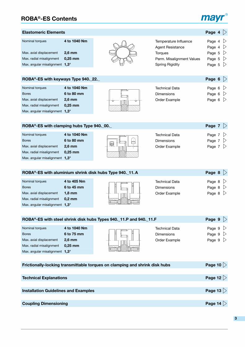
Elastomeric Elements Page 4
Nominal torques 4 to 1040 Nm Temperature Influence Page 4
Agent Resistance Page 4Max. axial displacement �,6 mm Torques Page 5Max. radial misalignment 0,�5 mm Perm. Misalignment Values Page 5Max. angular misalignment 1,3° Spring Rigidity Page 5
ROBA®-ES with keyways Type 940._��._ Page 6
Nominal torques 4 to 1040 Nm Technical Data Page 6Bores 6 to 80 mm Dimensions Page 6Max. axial displacement �,6 mm Order Example Page 6Max. radial misalignment 0,�5 mm
Max. angular misalignment 1,3°
ROBA®-ES with clamping hubs Type 940._00._ Page 7
Nominal torques 4 to 1040 Nm Technical Data Page 7Bores 6 to 80 mm Dimensions Page 7Max. axial displacement �,6 mm Order Example Page 7Max. radial misalignment 0,�5 mm
Max. angular misalignment 1,3°
ROBA®-ES with aluminium shrink disk hubs Type 940._11. A Page 8
Nominal torques 4 to 405 Nm Technical Data Page 8Bores 6 to 45 mm Dimensions Page 8Max. axial displacement 1,8 mm Order Example Page 8Max. radial misalignment 0,� mm
Max. angular misalignment 1,3°
ROBA®-ES with steel shrink disk hubs Types 940._11.P and 940._11.F Page 9
Nominal torques 4 to 1040 Nm Technical Data Page 9Bores 6 to 75 mm Dimensions Page 9Max. axial displacement �,6 mm Order Example Page 9Max. radial misalignment 0,�5 mm
Max. angular misalignment 1,3°
Frictionally-locking transmittable torques on clamping and shrink disk hubs Page 10
Technical Explanations Page 1�
Installation Guidelines and Examples Page 13
Coupling Dimensioning Page 14
3

Elastomeric Elements
ROBA®-ES elastomeric elements
The elastomeric elements are the central element of the ROBA®-ES-coupling. They define the application range as well as the shaft connection behaviour via the permitted torque, rigidity, damping and misalignment values.
By using a unique polyurethane material and a special injection procedure, it is possible to achieve a high dimensional accuracy and evenness in the teeth of the elastomeric element.
The elastomeric elements are available in different shore hardnesses.
The teeth of the elastomeric element are chamfered at the sides. This makes blind installation easier.
Temperature InfluenceThe ambient temperatures present during operation have a considerable effect on the dimensioning of a ROBA®-ES-coupling (see Dimensioning page 14).
Agent ResistanceThe elastomeric elements are very resistant against: • pure mineral oils (lubricating oils) • and anhydrous greases.They have a similar resistance against fuels such as • regular-grade petroleum • diesel oil • kerosene.Damage may occur after longer exposure to • alcohols or • aromatic fuels (super/four star petrol).
The elastomeric element material used is resistant to hydrolysis. In contrast to other polyurethane materials, water (including seawater) causes, even after years of exposure, no particular changes to the mechanical characteristics. Hot water, however, reduces the mechanical strength.
For information on contact with special agents or radiation, please contact the manufacturers.
DimensioningThe characteristics of ROBA®-ES couplings can be greatly varied by using different elastomeric elements. Due to different damping characteristics and the non-linear rigidity of the elastomer, this element also offers more parameters than the steel shaft connection, which should be taken into account on selection.
We therefore recommend careful, thorough coupling dimensioning (see Dimensioning page 14).
Elastomeric elementhardness[Shore]
Colour
Permitted temperature range
Permanent temperature Temporary max. temperature
80 Sh A Blue -50 to +80 °C -60 to +120 °C
92 Sh A Yellow -40 to +90 °C -50 to +120 °C
98 Sh A Red -30 to +90 °C -40 to +120 °C
64 Sh D Green -30 to +100 °C -40 to +140 °C
Please Observe:According to German notation, decimal points in this document are represented with a comma (e.g. 0,5 instead of 0.5).
We reserve the right to make dimensional and constructional alterations.4
ROBA®-ES elastomeric elements
Size
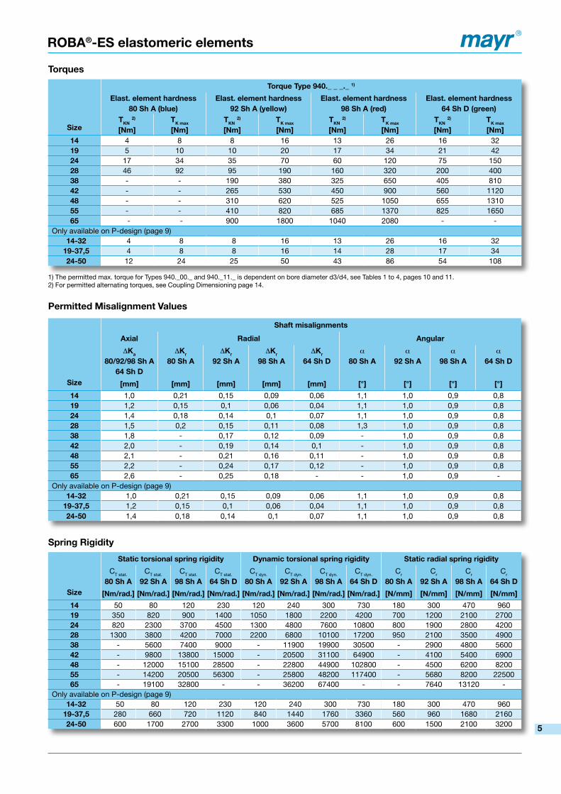
Torque Type 940._ _ _._ 1)
Elast. element hardness 80 Sh A (blue)
Elast. element hardness9� Sh A (yellow)
Elast. element hardness98 Sh A (red)
Elast. element hardness64 Sh D (green)
TKN �)
[Nm]TK max
[Nm]TKN �)
[Nm]TK max
[Nm]TKN �)
[Nm]TK max
[Nm]TKN �)
[Nm]TK max
[Nm]14 4 8 8 16 13 26 16 3219 5 10 10 20 17 34 21 42�4 17 34 35 70 60 120 75 150�8 46 92 95 190 160 320 200 40038 - - 190 380 325 650 405 8104� - - 265 530 450 900 560 112048 - - 310 620 525 1050 655 131055 - - 410 820 685 1370 825 165065 - - 900 1800 1040 2080 - -
Only available on P-design (page 9)14-3� 4 8 8 16 13 26 16 32
19-37,5 4 8 8 16 14 28 17 34�4-50 12 24 25 50 43 86 54 108
Torques
Permitted Misalignment Values
Spring Rigidity
1) The permitted max. torque for Types 940._00._ and 940._11._ is dependent on bore diameter d3/d4, see Tables 1 to 4, pages 10 and 11.2) For permitted alternating torques, see Coupling Dimensioning page 14.
Size
Shaft misalignments
Axial Radial Angular
DKa
80/9�/98 Sh A64 Sh D
DKr
80 Sh ADKr
9� Sh ADKr
98 Sh ADKr
64 Sh Da
80 Sh Aa
9� Sh Aa
98 Sh Aa
64 Sh D
[mm] [mm] [mm] [mm] [mm] [°] [°] [°] [°]
14 1,0 0,21 0,15 0,09 0,06 1,1 1,0 0,9 0,819 1,2 0,15 0,1 0,06 0,04 1,1 1,0 0,9 0,8�4 1,4 0,18 0,14 0,1 0,07 1,1 1,0 0,9 0,8�8 1,5 0,2 0,15 0,11 0,08 1,3 1,0 0,9 0,838 1,8 - 0,17 0,12 0,09 - 1,0 0,9 0,84� 2,0 - 0,19 0,14 0,1 - 1,0 0,9 0,848 2,1 - 0,21 0,16 0,11 - 1,0 0,9 0,855 2,2 - 0,24 0,17 0,12 - 1,0 0,9 0,865 2,6 - 0,25 0,18 - - 1,0 0,9 -
Only available on P-design (page 9)14-3� 1,0 0,21 0,15 0,09 0,06 1,1 1,0 0,9 0,8
19-37,5 1,2 0,15 0,1 0,06 0,04 1,1 1,0 0,9 0,8�4-50 1,4 0,18 0,14 0,1 0,07 1,1 1,0 0,9 0,8
Size
Static torsional spring rigidity Dynamic torsional spring rigidity Static radial spring rigidity
CT stat.
80 Sh ACT stat.
9� Sh ACT stat.
98 Sh ACT stat.
64 Sh DCT dyn.
80 Sh ACT dyn.
9� Sh ACT dyn.
98 Sh ACT dyn.
64 Sh DCr
80 Sh ACr
9� Sh ACr
98 Sh ACr
64 Sh D
[Nm/rad.] [Nm/rad.] [Nm/rad.] [Nm/rad.] [Nm/rad.] [Nm/rad.] [Nm/rad.] [Nm/rad.] [N/mm] [N/mm] [N/mm] [N/mm]
14 50 80 120 230 120 240 300 730 180 300 470 96019 350 820 900 1400 1050 1800 2200 4200 700 1200 2100 2700�4 820 2300 3700 4500 1300 4800 7600 10800 800 1900 2800 4200�8 1300 3800 4200 7000 2200 6800 10100 17200 950 2100 3500 490038 - 5600 7400 9000 - 11900 19900 30500 - 2900 4800 56004� - 9800 13800 15000 - 20500 31100 64900 - 4100 5400 690048 - 12000 15100 28500 - 22800 44900 102800 - 4500 6200 820055 - 14200 20500 56300 - 25800 48200 117400 - 5680 8200 2250065 - 19100 32800 - - 36200 67400 - - 7640 13120 -
Only available on P-design (page 9)14-3� 50 80 120 230 120 240 300 730 180 300 470 960
19-37,5 280 660 720 1120 840 1440 1760 3360 560 960 1680 2160�4-50 600 1700 2700 3300 1000 3600 5700 8100 600 1500 2100 3200 5

Ø D
H
Ø d
5
Ø d
5
L
tG
a
s
l1 (l1)bs
E
Ø d
H
Fig. 1: Type 940._22._
ROBA®-ES with keyways Type 940._��._ Sizes 14 to 65
Dimensi-ons
Size �)
14 19 �4 �8 38 4� 48 55 65
a 2 4 4 5 5 5 5 9 8
b 10 12 14 15 18 20 21 22 26
DH 30 40 55 65 80 95 105 120 135
dH 10,5 18 27 30 38 46 51 60 68
E 13 16 18 20 24 26 28 30 35
G M4 M5 M5 M6 M8 M8 M8 M10 M10
L 35 66 78 90 114 126 140 160 185
l1 11 25 30 35 45 50 56 65 75
s 1,5 2,0 2,0 2,5 3,0 3,0 3,5 4,0 4,5
t 5 10 10 15 15 20 25 20 20
ROBA®-ES with keyways Type 940._��._
Technical Data and BoresSize 1)
14 19 �4 �8 38 4� 48 55 65
Minimum hub bore �) d5 min [mm] 6 6 8 10 12 14 20 20 38
Maximum hub bore �) d5 max [mm] 15 24 28 38 45 55 60 70 80
Maximum speed nmax [rpm] 19000 14000 10600 8500 7100 6000 5600 5000 4600
Mass moments of inertia per hub and max. bore
J [10-6 kgm2] 2,8 20,4 50,8 200,3 400,6 2246 3786 8546 16043
Weight [kg] 0,020 0,066 0,132 0,253 0,455 1,85 2,52 4,14 5,96
1) Further sizes and Types available on request. We reserve the right to make dimensional and constructional alterations.2) Recommended tolerance connection H7/k6.
Order number
__ / 9 4 0 . __ 2 2 . __ / __ / __
Sizes
14
to
65
Elast. element hardness 98 Sh A (red)
Elast. element hardness 92 Sh A (yellow)
Elast. element hardness* 80 Sh A (blue)
Elast. element hardness** 64 Sh D (green)
0
1
5
6
Aluminium design up to size 38
Steel design from size 42
A
F
Bore ød5
H7
(see Table)
Bore ød5
H7
(see Table)
Example: 4� / 940.0��.F / Ød5 30 / Ød5 30 * Only up to size 28; ** Only up to size 55
Drawn offset
ROBA®-ES couplings are delivered as un-bored hub design (further processing to be carried out customer-side) or with a finish bore and keyway JS9 (DIN 6885/1). An adjusting screw is located in the hub for axial securement, which is offset by 180° to the keyway (see Fig. right).
Up to size 38, the hubs are made of aluminium. From size 42, they are made of steel.
Conventional bores can be delivered from stock.
6
Ø D
H
Ø d
3
Ø d
3
L
t1
M1
a
s
l1 (l1)
bs
E
Ø d
H
Ø D K
t2
ROBA®-ES with clamping hubs Type 940._00._ Sizes 14 to 65
Fig. �: Type 940._00._
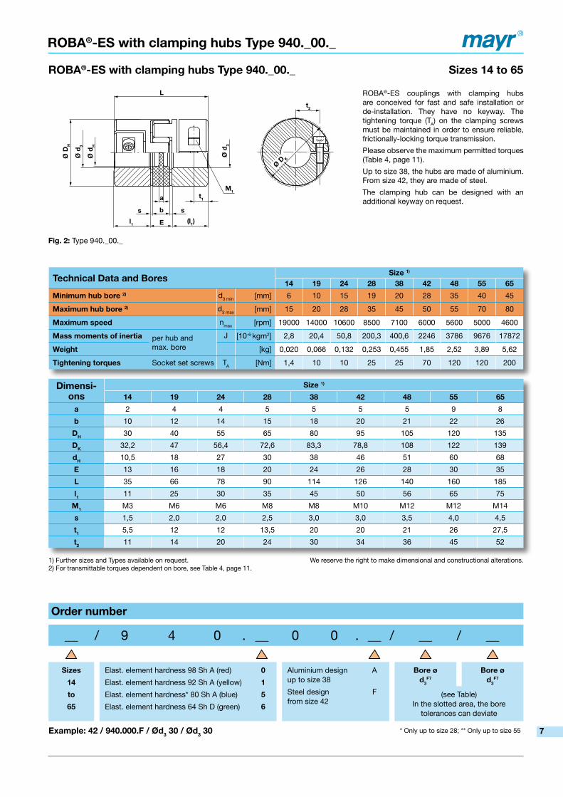
ROBA®-ES with clamping hubs Type 940._00._
Dimensi-ons
Size 1)
14 19 �4 �8 38 4� 48 55 65
a 2 4 4 5 5 5 5 9 8
b 10 12 14 15 18 20 21 22 26
DH 30 40 55 65 80 95 105 120 135
DK 32,2 47 56,4 72,6 83,3 78,8 108 122 139
dH 10,5 18 27 30 38 46 51 60 68
E 13 16 18 20 24 26 28 30 35
L 35 66 78 90 114 126 140 160 185
l1 11 25 30 35 45 50 56 65 75
M1 M3 M6 M6 M8 M8 M10 M12 M12 M14
s 1,5 2,0 2,0 2,5 3,0 3,0 3,5 4,0 4,5
t1 5,5 12 12 13,5 20 20 21 26 27,5
t� 11 14 20 24 30 34 36 45 52
Technical Data and BoresSize 1)
14 19 �4 �8 38 4� 48 55 65
Minimum hub bore �) d3 min [mm] 6 10 15 19 20 28 35 40 45
Maximum hub bore �) d3 max [mm] 15 20 28 35 45 50 55 70 80
Maximum speed nmax [rpm] 19000 14000 10600 8500 7100 6000 5600 5000 4600
Mass moments of inertia per hub and max. bore
J [10-6 kgm2] 2,8 20,4 50,8 200,3 400,6 2246 3786 9676 17872
Weight [kg] 0,020 0,066 0,132 0,253 0,455 1,85 2,52 3,89 5,62
Tightening torques Socket set screws TA [Nm] 1,4 10 10 25 25 70 120 120 200
1) Further sizes and Types available on request. We reserve the right to make dimensional and constructional alterations.2) For transmittable torques dependent on bore, see Table 4, page 11.
Order number
__ / 9 4 0 . __ 0 0 . __ / __ / __
Sizes
14
to
65
Elast. element hardness 98 Sh A (red)
Elast. element hardness 92 Sh A (yellow)
Elast. element hardness* 80 Sh A (blue)
Elast. element hardness 64 Sh D (green)
0
1
5
6
Aluminium design up to size 38
Steel designfrom size 42
A
F
Bore ød3
F7
Bore ød3
F7
(see Table) In the slotted area, the bore
tolerances can deviate
Example: 4� / 940.000.F / Ød3 30 / Ød3 30 * Only up to size 28; ** Only up to size 55
ROBA®-ES couplings with clamping hubs are conceived for fast and safe installation or de-installation. They have no keyway. The tightening torque (TA) on the clamping screws must be maintained in order to ensure reliable, frictionally-locking torque transmission.
Please observe the maximum permitted torques (Table 4, page 11).
Up to size 38, the hubs are made of aluminium. From size 42, they are made of steel.
The clamping hub can be designed with an additional keyway on request.
7

Ø D
H
Ø d
4
Ø d
4
L
a
s
l1 (l1)
bs
E
Ø d
H
1 mm1 mm
Fig. 3: Type 940._11.A
ROBA®-with aluminium shrink disk hubs Type 940._11.A Sizes 14 to 38
Dimensi-ons
Size
14 19 �4 �8 38
a 2 4 4 5 5
b 10 12 14 15 18
DH 30 40 55 65 80
dH 10,5 18 27 30 38
E 13 16 18 20 24
L 50 66 78 90 114
l1 18,5 25 30 35 45
M� 4 x M3 6 x M4 4 x M5 8 x M5 8 x M6
s 1,5 2,0 2,0 2,5 3,0
1) For transmittable torques dependent on bore, see Table 1, page 10. We reserve the right to make dimensional and constructional alterations.
Order number
__ / 9 4 0 . __ 1 1 . A / __ / __
Sizes
14
to
38
Elast. element hardness 98 Sh A (red)
Elast. element hardness 92 Sh A (yellow)
Elast. element hardness* 80 Sh A (blue)
Ealst. element hardness** 64 Sh D (green)
0
1
5
6
Aluminium design A Bore ød4
H7
(see Table)
Bore ød4
H7
(see Table)
Example: 38 / 940.011.A / Ød4 30 / Ød4 30 *Only up to size 28; ** Only up to size 55
ROBA®-ES with aluminium shrink disk hubs Type 940._11.A
On this design, the hub body is made of aluminium and the ring of phosphated, annealed steel. The design is constructionally identical to the P-design (page 9). The symmetry, the absence of keyways and radial bores produces an optimum shaft run out. Therefore, much higher torques are possible compared to the other hub designs (please observe the Balancing Diagram, page 12).
The torque is transmitted via frictional locking onto the shaft. Therefore, please observe the maximum torques on this shaft-hub connection (Table 1, page 10).
Technical Data and BoresSize
14 19 �4 �8 38
Minimum hub bore 1) d4 min [mm] 6 10 15 19 20
Maximum hub bore 1) d4 max [mm] 14 20 28 38 45
Maximum speed nmax [rpm] 28000 21000 15500 13200 10500
Mass moments of inertia per hub and max. bore
J [10-6 kgm2] 7 31 135 313 960
Weight [kg] 0,049 0,12 0,28 0,45 0,95
Tightening torques Clamping screws TA [Nm] 1,3 3,0 6,0 6,0 10,0
8

Ø D
H
Ø d
4
Ø d
4
L
a
s
l1 (l1)
bs
E
Ø d
H
Ø d
61 mm1 mm
t2
M2
Ø D
H
Ø d
4
Ø d
4
L
a
s
l1 (l1)
bs
E
Ø d
H
Ø d
6
1 mm1 mm
t2
M2
Ø d
7*
ROBA®-ES with steel shrink disk hubs Type 940._11._ Sizes 14-3� to 65
Fig. 4: Type 940._11.P – Sizes 14 to 38 Type 940._11.F – Sizes 42 to 65
Dimensi-ons
Size
14-3� 19-37,5 19 �4-50 �4 �8 38 4� 48 55 65a 2 4 4 4 4 5 5 5 5 9 8b 10 12 12 14 14 15 18 20 21 22 26
DH 32 37,5 40 50 55 65 80 95 105 120 135dH 10,5 18 18 27 27 30 38 46 51 60 68d6 17 19 22 29 30 40 46 55 60 72 77
d7 * 8,5 9,5 9,5 12,5 12,5 14,5 - - - - -E 13 16 16 18 18 20 24 26 28 30 35L 50 66 66 78 78 90 114 126 140 160 185l1 18,5 25 25 30 30 35 45 50 56 65 75
M� 4 x M3 6 x M4 6 x M4 4 x M5 4 x M5 8 x M5 8 x M6 4 x M8 4 x M8 4 x M10 4 x M12s 1,5 2,0 2,0 2,0 2,0 2,5 3,0 3,0 3,5 4,0 4,5t� 3 4 4 5 5 5 5 5 6 7 7
Technical Data and BoresSize
14-3� 19-37,5 19 �4-50 �4 �8 38 4� 48 55 65
Minimum hub bore 1) d4 min [mm] 6 10 10 15 15 19 20 28 35 40 45
Maximum hub bore 1) d4 max [mm] 14 16 20 24 28 38 45 50 60 70 75
DIN-bore * d4 [mm] 14 16 19 24 25 35 - - - - -
Maximum speed nmax [rpm] 28000 21000 21000 15500 15500 13200 10500 9000 8000 6300 5600
Mass moments of inertia per hub and max. bore
J [10-6 kgm2] 11 37 46 136 201 438 1320 3170 5200 9069 17209
Weight [kg] 0,1 0,16 0,19 0,33 0,44 0,64 1,3 2,3 3,1 3,61 5,52
Tightening torques Clamping screws TA [Nm] 1,3 3,0 3,0 6,0 6,0 6,0 10 25 30 52 90
1) For transmittable torques dependent on bore, see Tables 2 and 3, pages 10 and 11. We reserve the right to make dimensional and constructional alterations.* Elastomeric elements with DIN bore only available with 98 Sh A (red), Type 940.011.P
Order number
__ / 9 4 0 . __ 1 1 . __ / __ / __ / __
Sizes
14-3�
to
65
Elast. element hardness 98 Sh A (red)
Elast. element hardness 92 Sh A (yellow)
Elast. element hardness* 80 Sh A (blue)
Elast. element hardness** 64 Sh D (green)
0
1
5
6
Steel design up to size 38
Steel design from size 42
P
F
Bore ø Bore ø Design
- DIN
- No values for standard
d4H6
up tosize 38
d4H7
fromsize 42
d4H6
up tosize 38
d4H7
fromsize 42
Example: 4� / 940.011.F / Ød4 30 / Ød4 30 *Only up to size 28; ** Only up to size 55
ROBA®-ES with steel shrink disk hubs Type 940._11._
On this design, the hub body is made of steel (oiled) and the ring of phosphated, annealed steel. This design is available in a stand-ard variant and a variant according to DIN 69002. The DIN variant has an elastomeric element with a central, standardised bore and standardised bore diameters in the hubs. The DIN variants are
conceived for use in short bore spindles and multi-spindle heads. Because of the steel hubs, this DIN design combines robustness with precision. This design should be selected in preference to others, in particular on applications with heavily tumescent or alternating loads.
Fig. 5: Type 940.011.P Sizes 14-32 to 28 acc. DIN 69002
(see Table) (see Table)
9

Frictionally-locking transmittable torques
Transmittable torques for shrink disk hubs made of aluminium – dependent on bore - Type 940._11. A
BoreSize
14 19 �4 �8 38
Frictionally-locking transmittable torques Shrink disk hubsmade of aluminium
Valid for H7 / k6
TR [Nm]
Ø6 7 - - - -Ø7 9 - - - -Ø8 11 - - - -Ø9 13 - - - -Ø10 15 33 - - -Ø11 17 38 - - -Ø14 24 55 - - -Ø15 - 61 56 - -Ø16 - 67 62 - -Ø17 - 73 68 - -Ø18 - 78 74 - -Ø19 - 84 81 141 -Ø20 - 88 87 153 197Ø22 - - 100 177 228Ø24 - - 120 203 261Ø25 - - 125 216 279Ø28 - - 135 256 332Ø30 - - - 282 368Ø32 - - - 308 405Ø35 - - - 343 460Ø38 - - - 373 513Ø40 - - - - 547Ø42 - - - - 577Ø45 - - - - 617
Transmittable torques for shrink disk hubs made of steel – dependent on bore - Type 940._11. P
BoreSize
14-3� 19-37,5 19 �4-50 �4 �8 38
Frictionally-locking transmittable torques Shrink disk hubsmade of steel
Valid for H6 / k6
TR [Nm]
Ø6 7 - - - - - -Ø7 9 - - - - - -Ø8 11 - - - - - -Ø9 13 - - - - - -Ø10 15 26 33 - - - -Ø11 17 30 38 - - - -Ø14 25 45 55 - - - -Ø15 - 50 61 45 56 - -Ø16 - 60 67 50 62 - -Ø17 - - 73 54 68 - -Ø18 - - 78 60 74 - -Ø19 - - 84 65 81 141 -Ø20 - - 88 70 87 153 197Ø22 - - - 85 100 177 228Ø24 - - - 112 120 203 261Ø25 - - - - 125 216 279Ø28 - - - - 135 256 332Ø30 - - - - - 282 368Ø32 - - - - - 308 405Ø35 - - - - - 343 460Ø38 - - - - - 373 513Ø40 - - - - - - 547Ø42 - - - - - - 577Ø45 - - - - - - 617
Table 1
Table �
The transmittable torques on the clamping connection take the max. tolerance backlash for shaft tolerance k6 / bore H7 into account.With larger tolerance backlash, the torque is reduced.
The transmittable torques on the clamping connection take the max. tolerance backlash for shaft tolerance k6 / bore H6 into account. With larger tolerance backlash, the torque is reduced.
10

BoreSize
14 19 �4 �8 38 4� 48 55 65
Frictionally-lockingtransmittable torquesClamping hubs
Valid for F7 / k6
TR [Nm]
Ø6 2,5 - - - - - - - -Ø7 3,0 - - - - - - - -Ø8 3,4 - - - - - - - -Ø9 3,8 - - - - - - - -Ø10 4,2 23 - - - - - - -Ø11 4,7 25 - - - - - - -Ø12 5,1 27 - - - - - - -Ø14 6,0 32 - - - - - - -Ø15 6,4 34 34 - - - - - -Ø16 - 36 36 - - - - - -Ø19 - 43 43 79 - - - - -Ø20 - 45 45 83 83 - - - -Ø22 - - 50 91 91 - - - -Ø24 - - 54 100 100 - - - -Ø25 - - 57 104 104 - - - -Ø28 - - 63 116 116 208 - - -Ø30 - - - 124 124 228 - - -Ø32 - - - 133 133 248 - - -Ø35 - - - 145 145 280 350 - -Ø38 - - - - 158 315 390 - -Ø40 - - - - 166 340 420 340 -Ø42 - - - - 174 365 455 365 -Ø45 - - - - 187 404 505 405 545Ø48 - - - - - 442 560 435 590Ø50 - - - - - 470 600 465 630Ø52 - - - - - - 640 490 662Ø55 - - - - - - 705 525 710Ø58 - - - - - - - 570 764Ø60 - - - - - - - 600 800Ø62 - - - - - - - 625 840Ø65 - - - - - - - 665 900Ø68 - - - - - - - 700 954Ø70 - - - - - - - 740 990Ø72 - - - - - - - - 1032Ø75 - - - - - - - - 1095Ø78 - - - - - - - - 1158Ø80 - - - - - - - - 1200
Transmittable torques for clamping hubs – dependent on bore – Type 940._00._
Frictionally-locking transmittable torques
Transmittable torques for shrink disk hubs made of steel – dependent on bore – Type 940._11. F
BoreSize
4� 48 55 65
Frictionially-lockingtransmittable torques Shrink disk hubsmade of steel
Valid for H7 / k6
TR [Nm]
Ø28 300 - - -Ø30 350 - - -Ø32 400 - - -Ø35 500 450 - -Ø38 600 500 - -Ø40 680 600 723 -Ø42 730 720 814 -Ø45 790 850 946 1402Ø48 850 1000 1085 1596Ø50 880 1180 1187 1731Ø52 - 1270 1284 1873Ø55 - 1353 1436 2095Ø58 - 1428 1585 2308Ø60 - 1471 1682 2420Ø62 - - 1795 2570Ø65 - - 1943 2750Ø68 - - 2100 2989Ø70 - - 2207 3157Ø72 - - - 3306Ø75 - - - 3550
Table 3
Table 4
The transmittable torques on the clamping connection take the max. tolerance backlash for shaft tolerance k6 / bore H7 into account. With larger tolerance backlash, the torque is reduced.
The transmittable torques on the clamping connection take the max. tolerance backlash for shaft tolerance k6 / bore F7 into account. With larger tolerance backlash, the torque is reduced. 11

30 000
25 000
20 000
15 000
10 000
5 000
014 19 24 28 38 42 48 55 65
nG
nmax
ROBA®-ES Technical Explanations
Coupling hub
Flexible intermediate ring
Technical Explanations
Fig. 6
ROBA®-ES stands for flexible (E), backlash-free (S) shaft coupling. The device consists of two coupling hubs and a flexible, star-shaped intermediate ring (Fig. 6).
ROBA®-ES couplings are conceived specially for backlash-free operation at comparatively high speeds.
ROBA®-ES couplings are mainly used in measurement and regulatory technology as well as in control and procedure technology.
State of Delivery
ROBA®-ES couplings are delivered manufacturer-assembled. The star-shaped intermediate ring must be pressed under light pre- tension (Fig. 7) into the specially formed jaws.
The principle of backlash-free torque transmission is possible due to this pre-tension.
ROBA®-ES couplings are delivered in four torque variations; that is with four different flexible intermediate rings varying in shore hardness and colour (see Type key page 5).
Due to the small construction dimensions and therefore the low mass moments of inertia, the device allows itself to be installed even into small installation spaces.
Fig. 7
Shaft Misalignments
The ROBA®-ES coupling is capable of compensating for radial, axial and angular shaft misalignments (Fig. 9), without losing their resistance to backlash. However, the permitted shaft misalignments shown on page 5 must not simultaneously reach their maximum value. If more than one kind of misalignment takes place simultaneously, they influence each other. This means that the permitted misalignment values are dependent on one another (see Fig. 8).Therefore, the sum total of the actual misalignments in percent of the maximum value may not exceed 100 %.The permitted misalignment values given on page 5 refer to coupling operation at nominal torque, an ambient temperature of +30 °C and an operating speed of 1500 rpm.
Radial misalignment Axial displacement
Fig. 8
Fig. 9
Angular misalignm
ent DKw [%
]
Axial displacement DKa [%]
Rad
ial m
isal
ignm
ent D
Kr [
%]
DKa
DK
r
a
L
Balancing
Key hubs and clamping hubs:Key hubs and clamping hubs rotate at maximum speed with a circumferential speed of 30 m/s. They are not balanced for standard delivery.
Shrink disk hubs:Shrink disk hubs can maintain balance quality G = 6,3 up to speed nG (equals c. 30 m/s) without needing to be balanced. Above this speed, we recommend balancing. The hubs are balanced individually. Diagram 1 shows reference values. We recommend you use these values to balance the coupling components.
Smooth running of a machine or system is not only dependent on the balance quality of the coupling, but also on many parameters such as rigidity or distance to the adjacent bearing. Therefore there are no fixed rules in which conditions you have to balance.
Size
Spe
ed [r
pm]
Diagram 1: Balancing the shrink disk hubs
Balancing recommended
Angular misalignment1�

ROBA®-ES Installation Guidelines and Examples
Installation Examples
Fig. 10: ROBA®-ES with clamping hubs
Fig. 11: ROBA®-ES with keyways
Fig. 1�: ROBA®-ES with shrink disks
Installation of the shrink disk hubs (ROBA®-ES Type 940._11._)
The conical surfaces of the shrink disk hubs are greased manufacturer-side with a special grease (should the device be cleaned, the device must be re-greased with special grease).
- Push the shrink disk hubs using a suitable device into both shaft ends, align them and tighten the clamping screws lightly up to their limits.
- Tighten the clamping screws evenly stepwise and cross-wise to the specified tightening torque (see pages 8 and 9) using a torque wrench.
- For de-installation, loosen all clamping screws by several thread turns.
- The clamping screws located next to the tapped extracting holes must be screwed out, and then screwed into the tapped extracting holes up to their limits.
- Tighten the clamping screws evenly and crosswise. This forces the shrink disk away from the conical shrink disk hub.
Safety Regulations
The coupling rotates during operation. It must be secured customer-side against inadvertent contact. Installation and maintenance must be carried out by personnel who have been trained accordingly.
Installation Guidelines – Installation
Due to its optimized construction, the ROBA®-ES coupling can be inserted axially onto the input or output shafts after installation of the hubs. Subsequent screwing-on and complicated special- construction housing is no longer necessary (see Installation Example page 13).
Please Observe!!!
The installation or installation dimensions must be kept to so that there is no facing-side pressure on the elastomeric element after clutch installation has been completed, meaning that the elastomeric element must not be distorted axially.
By keeping to the installation dimensions (in particular dimension “E“, see Dimension Figs. and Dimension Tables, pages 6 – 9), the elastomeric element’s axial flexibility remains guaranteed.
On elastomeric elements with differing numbers of nubs, the side with the larger number of nubs must be installed first (for easier installation).
Due to the pre-tension on the flexible elastomeric element, an axial installation force is required when joining the coupling hubs.
The axial installation force required can be reduced by lightly greasing the elastomeric element. OBSERVE: Only use grease based on mineral oil without additives. Vaseline is also suitable.
13

ROBA®-ES Dimensioning
ROBA®-ES Coupling Dimensioning
1. Approximate calculation of the coupling torque: 1.1. TN from the nominal capacity TN =
1.2. Dynamic torques TS and TW (5.1 and 5.�):
Input-side excitation: Load-side excitation:
Impact torque: TS = TAS x x SA Impact torque: TS = TLS x x SL
Alternating torque: TW = TAW x x VR Alternating torque: TW = TLW x x VR
�. Comparison of torques occurring in the coupling with the permitted torques The coupling must be dimensioned so that the loads occurring do not exceed the permitted values in any operating condition.
2.1. Load due to nominal torque
TKN ≥ TN x Sd
2.2. Load due to torque impacts (5.3)
TK max ≥ TS x SZ x Sd + TN x S
d
2.3. Load due to resonance passing through (5.4)
TK max ≥ TS x SZ x Sd x VR + TN x S
d
2.4. Load due to constantly alternating torque – cycle operation (5.5 and 5.6)
Permitted alternating torque on coupling:
TKW = 0,�5 x TKN (for aluminium hubs)
TKW = 0,35 x TKN (for steel hubs)
TKW ≥ TW x Sd x Sf
3. Inspection of permitted misalignments ∆Ka ≥ ∆Wa x S
d
∆Kr ≥ ∆Wr x Sd x Sn
∆Kw ≥ ∆Ww x Sd x Sn
If more than one misalignment type occurs at the same time, please observe Fig. 8 (page 12).
4. Frictional locking inspection on hub connection TR > Tmax : Tmax is the maximum torque occurring in the coupling.
Values for TR can be found on pages 10 and 11.
5. Explanations 5.1. The torque definition on the coupling is applicable if the shaft coupling in the system is the torsionally softest element, and
therefore the system can be considered as a double-mass oscillator. If this is not the case, the calculation of the torque on the coupling requires a more detailed calculation procedure.
5.2. The impact factors SA / SL describe the impact progression. A rectangular progression of the impact torque is the heaviest impact (SA/SL=2,0). A flat sinus progression of the impact torque is a light impact (SA/SL=1,2).
5.3. TS, the peak torque in the coupling, is the maximum torque on the coupling during the impact minus the system torque having an effect on the coupling during normal operation.
5.4. TS = Tmax. impact - TN
5.4. If a drive is operated supercritically, meaning that the operating speed n lies above the resonance speed nR, then resonance passing through causes particular loads.
5.4. If the resonance passes through quickly below the operating speed, only a few resonance peaks occur. The alternating torque in resonance can therefore be compared to the maximum torque on the coupling (see also 5.6)
5.5. Sf takes the frequency dependency of lifetime into account. The frequency dependency is first taken into account above 5 Hz.
5.6. On appreciable vibration excitation, the resonance must be moved out of the operating range by selecting a suitable coupling spring rigidity.
9550 x PAN/LN
n
JL
JA + JL
JA
JA + JL
JL
JA + JL
JA
JA + JL
14

ROBA®-ES Dimensioning
f shows the load alternation per second (Hz = s-1)
SZ = Start-up factor/impact frequency
S/h 0-100 101-200 201-400 401-800 801-1600
SZ 1 1,2 1,4 1,6 1,8
Sf = Frequency factor
f in Hz ≤ 5 > 5
Sf 1 √ f 5
SL or SA = Impact factor
Impacts SA or SL
Light impacts 1,2
Medium impacts 1,6
Heavy impacts 2,0
Sd = Safety factor for temperature
T [°C] - 30 °C / + 30 °C + 60 °C + 90 °C
Sd 1 1,5 2
Terms
PAN/LN [kW] Input-side/load-side capacityTR [Nm] Transmittable torque (frictional locking,
Tables pages 10,11)TAS/AW [Nm] Excitational torque input-sideTLS/LW [Nm] Excitational torque load-sideTN [Nm] System torqueTW [Nm] System alternating torqueTS [Nm] Peak torqueTmax [Nm] Maxiumum torque in the couplingTKN [Nm] Permitted nominal torqueTKmax [Nm] Permitted maximum torqueTKW [Nm] Permitted permanent alternating torqueJA [kgm2] Mass moment of inertia, input-sideJL [kgm2] Mass moment of inertia, load-side∆Ka [mm] Permitted axial displacement∆Kr [mm] Permitted radial misalignment
∆Kw [°] Permitted angular misalignment∆Wa [mm] Axial shaft displacement∆Wr [mm] Radial shaft misalignment∆Ww [°] Angular shaft misalignmentcT [Nm/rad] Spring rigidityn [rpm] Nominal speednR [rpm] Resonance speedSA/L [ - ] Impact factor input-side/load-sideSn [ - ] Speed factorSZ [ - ] Start-up factor/impact frequencyS
d [ - ] Temperature factor
Sf [ - ] Frequency factorVR [ - ] Resonance factorf [1/s]=[Hz] Load factorfR [Hz] Resonance frequency
Service factors for Coupling Dimensioning
VR = Resonance factor
Blue: elast. element 80 Sh A
Yellow: elast. element 92 Sh A
Red: elast. element 98 Sh A
Green: elast. element 64 Sh D
nR = Resonance speed
nR = √ CT dyn. [rpm]
fR = Resonance frequency
fR = √CT dyn. [Hz]
JA+JL
JAxJL
30π
JA+JL
JAxJL
12π
VR
n/nR
f/fR0,6 0,8 1,2 1,4
10
8
6
4
2
Sn = Speed factor
n [rpm]
Sn
4000 6000 8000 10000 12000 14000
3,5
3
2,5
2
1,5
15

Representatives
More representatives:Austria, Benelux States, Brazil, Canada, Czech Republic, Denmark, Finland, Greece, Hongkong, Hungary, Indonesia, Israel, Malaysia, New Zealand, Norway, Philippines, Poland, Romania, Russia, Slovakia, Slovenia, Spain, Sweden, Thailand, TurkeyYou can find the complete address for the representative responsible for your area underwww.mayr.de in the internet.
Headquarters
Chr. Mayr GmbH + Co. KGEichenstrasse 1, D-87665 MauerstettenTel.: 0 83 41/8 04-0, Fax: 0 83 41/80 44 21www.mayr.de, E-Mail: [email protected]
Branch office
Service Germany
Baden-WürttembergEsslinger Straße 770771 Leinfelden-EchterdingenTel.: 07 11/45 96 01 0Fax: 07 11/45 96 01 10
BavariaEichenstrasse 187665 MauerstettenTel.: 0 83 41/80 41 04Fax: 0 83 41/80 44 23
ChemnitzBornaer Straße 20509114 ChemnitzTel.: 03 71/4 74 18 96Fax: 03 71/4 74 18 95
FrankenUnterer Markt 991217 HersbruckTel.: 0 91 51/81 48 64Fax: 0 91 51/81 62 45
KamenLünener Strasse 21159174 KamenTel.: 0 23 07/23 63 85Fax: 0 23 07/24 26 74
NorthSchiefer Brink 832699 ExtertalTel.: 0 57 54/9 20 77Fax: 0 57 54/9 20 78
Rhine-MainJägerstrasse 464739 Höchst Tel.: 0 61 63/48 88Fax: 0 61 63/46 47
ChinaMayr ZhangjiagangPower Transmission Co., Ltd. Changxing Road No. 16,215600 ZhangjiagangTel.: 05 12/58 91-75 65Fax: 05 12/58 91-75 [email protected]
Great BritainMayr Transmissions Ltd.Valley Road, Business ParkKeighley, BD21 4LZWest YorkshireTel.: 0 15 35/66 39 00Fax: 0 15 35/66 32 [email protected]
FranceMayr France S.A.Z.A.L. du MinopoleBP 1662160 Bully-Les-MinesTel.: 03.21.72.91.91Fax: [email protected]
ItalyMayr Italia S.r.l.Viale Veneto, 335020 Saonara (PD)Tel.: 0 49/8 79 10 20Fax: 0 49/8 79 10 [email protected]
SingaporeMayr Transmission (S) PTE Ltd.No. 8 Boon Lay Way Unit 03-06, TradeHub 21Singapore 609964 Tel.: 00 65/65 60 12 30Fax: 00 65/65 60 10 [email protected]
SwitzerlandMayr Kupplungen AGTobeläckerstrasse 118212 Neuhausen am RheinfallTel.: 0 52/6 74 08 70Fax: 0 52/6 74 08 [email protected]
USAMayr Corporation4 North StreetWaldwickNJ 07463Tel.: 2 01/4 45-72 10Fax: 2 01/4 45-80 [email protected]
AustraliaTransmission Australia Pty. Ltd.22 Corporate Ave,3178 Rowville, VictoriaAustralienTel.: 0 39/7 55 44 44Fax: 0 39/7 55 44 [email protected]
ChinaMayr Power Transmission Co., Ltd. Shanghai Representative Office Room 2206, No. 888 Yishan Road200233 Shanghai, VR ChinaTel.: 0 21/64 32 01 60Fax: 0 21/64 57 56 [email protected]
IndiaNational EngineeringCompany (NENCO)J-225, M.I.D.C. Bhosari Pune 411026Tel.: 0 20/27 47 45 29Fax: 0 20/27 47 02 [email protected]
JapanMATSUI Corporation2-4-7 AzabudaiMinato-kuTokyo 106-8641Tel.: 03/35 86-41 41Fax: 03/32 24 24 [email protected]
South AfricaTorque TransferPrivate Bag 9Elandsfonstein 1406Tel.: 0 11/3 45 80 00Fax: 0 11/9 74 05 [email protected]
South KoreaMayr Korea Co. Ltd.Room No.1002, 10th floor, Nex Zone, SK TECHNOPARK, 77-1, SungSan-Dong, SungSan-Gu, Changwon, KoreaTel.: 0 55/2 62-40 24Fax: 0 55/2 62-40 [email protected]
TaiwanGerman Tech Auto Co., Ltd.No. 162, Hsin sheng Road, Taishan Hsiang,Taipei County 243, Taiwan R.O.C.Tel.: 02/29 03 09 39Fax: 02/29 03 06 [email protected]
Machine tools Applications in ChinaDynamic Power Transmission Co., Ltd. Block 5th, No. 1699, Songze Road, Xujing Industrial Zone201702 Shanghai, ChinaTel.: 021/59883978Fax: 021/[email protected]
your reliable partner
22/0
2/20
11 S
C
HagenIm Langenstück 658093 HagenTel.: 0 23 31/78 03 0Fax: 0 23 31/78 03 25