installation and user manual akvaconnect feeding manuals/akva... · installation and user manual...
TRANSCRIPT

Page 1 of 93
Installation and user manual AKVAconnect Feeding Document no. DC10000644
INSTALLATION AND USER MANUAL
AKVAconnect Feeding
2 15.02.13 Second revision - Hopper included EBL JS
1 19.11.13 First revision EBL JS
Rev Date Issued Issued by Approved
Document no.: DC10000644 Project no.: 84795-01

Page 2 of 93
Installation and user manual AKVAconnect Feeding Document no. DC10000644
The information in this document is subject to change
without notice and should not be construed as a
commitment by AKVA group ASA.
AKVA group ASA assumes no responsibility for any errors
that may appear in this document.
In no event shall AKVA group ASA be liable for incidental
or consequential damages arising from use of this
document or of the software and hardware
described in this document.
We reserve all rights in this document and in the
information contained therein. Reproduction, use or
disclosure to third parties without express
authority is strictly forbidden.
Additional copies of this document may be obtained from
AKVA group ASA at its current charge.
© 2014 AKVA group ASA (NO)
AKVA group ASA

Page 3 of 93
Installation and user manual AKVAconnect Feeding Document no. DC10000644
Table of contents
1 Safety ........................................................................................................5
1.2 Safety symbols ............................................................................................5
2 Introduction - AKVA group ASA .................................................................6
2.1 Contact information .....................................................................................7
3 Information - AKVAconnect Feeding .........................................................9
3.1 Key functionality ........................................................................................ 10
4 Installation .............................................................................................11
5 License ....................................................................................................16
5.1 License request ......................................................................................... 16
5.2 Add license ............................................................................................... 17
6 The AKVAconnect menu ..........................................................................18
7 Roles and users .......................................................................................19
7.1 Add Roles ................................................................................................. 20
7.2 Add users ................................................................................................. 22
7.3 Hints......................................................................................................... 23
8 Application builder ..................................................................................24
8.1 Create a new application ............................................................................ 24
8.2 Adding objects to the feed line control area.................................................... 28
8.3 Re-naming the feed line ............................................................................. 33
8.4 Grid ......................................................................................................... 33
8.5 Bottom buttons ......................................................................................... 34
8.6 Various feed systems ................................................................................. 36
8.7 Adding more feed lines ............................................................................... 39
8.8 Hints ........................................................................................................ 40
9 Set up process view ................................................................................41
9.1 The process image builder .......................................................................... 42
9.2 Add components to the ‘Process image’ - Company adjustment ....................... 44
9.3 Define the process view............................................................................... 46

Page 4 of 93
Installation and user manual AKVAconnect Feeding Document no. DC10000644
10 Feed settings ...........................................................................................55
10.1 Settings (Feeding settings) ......................................................................... 55
10.2 Customize system ..................................................................................... 56
10.3 Feed tables ............................................................................................... 58
10.4 Adjust transport times and blower speed ...................................................... 59
10.5 Machinery control (Machinery monitor) ......................................................... 60
10.6 Machinery parameters (Feedline parameters) ................................................ 61
10.7 Capacity utilization .................................................................................... 63
10.8 Hints ........................................................................................................ 66
11 Using AKVAconnect Feeding ....................................................................68
11.1 The top menu ........................................................................................... 68
11.2 Tank settings ............................................................................................ 72
11.3 Silo .......................................................................................................... 78
11.4 Calibrate doser .......................................................................................... 80
11.5 Feed line control ........................................................................................ 83
11.6 Register mortality ...................................................................................... 85
12 Troubleshooting ......................................................................................86
Appendix A - Index ..........................................................................................87
Appendix B - Deviation form ............................................................................91
Appendix C - Notes ..........................................................................................92
Page 5 of 93
Installation and user manual AKVAconnect Feeding Document no. DC10000644
1 Safety
Safety for the users of our equipment is top focus when AKVA
group ASA develop new products and product manuals.
We therefore strongly recommend that everyone that use the
equipment, all that perform any type of repairs, service or other
maintenance to the product, and all that work in areas where the
product is installed read this entire manual and at least the
safety chapter.
This recommendation is based on both personnel safety as well
as a desire to keep the products in order and avoid damages
risked if the safety instructions are not followed.
1.1 Safety symbols
The following safety symbols are used in this manual:
Information
Important information
Show caution - may cause light personnel injuries and
damages to the equipment.
1.1.1 Other symbols
Go to page or chapter for further information or instructions.

Page 6 of 93
Installation and user manual AKVAconnect Feeding Document no. DC10000644
2 Introduction - AKVA group ASA
This manual is part of the equipment delivered with
AKVAconnect Feeding. Keep the manual as long as Your
AKVA products are in use, and make sure to write down
any changes made to the equipment as they happen.
Thank you for choosing AKVA group ASA as supplier for Your
process control platform. Do not hesitate contacting us if You
need more information regarding use or maintenance for Your
product.
With four main brands, AKVA group ASA is a world leading
supplier of technical aquaculture equipment. Since 1980 we
have developed and produced fish farming equipment, both for
cages at sea and for land based hatcheries. AKVA represents an
industrial standard, which is presumed to be the turn key to the
future. Research, project management, fast deliveries and
customer follow-up have been our focus to ensure that we
contribute to a positive development within the agriculture
industry. Our goal is to deliver the best possible and most cost
efficient equipment in order to keep preserving sustainable
farming.
We have a wide variety of products, for example: plastic and
steel cages, high pressure washers, net washers, boats, feed
barges, feeding systems, cameras, sensor systems, under water
lighting, software for fish farming and recycling systems.
This User Manual enables the operator to install and use
AKVAconnect Feeding in a safe and economically way. Safety –
both for the user and for the equipment, is our main focus when
developing products.
All of our equipment are pre-installed, tested and delivered from
our own production department. This means that you have total
control over which components You can choose from, grouping
Page 7 of 93
Installation and user manual AKVAconnect Feeding Document no. DC10000644
collocation, testing and deliveries. Our production staff consists
of people with great expertise and engagement for
producing the best possible products for you. Having our own
production site gives you excellent service in case something
should go wrong, or if you are in need of any assistance. Our
service staff is available on the telephone or on location to assist
you if necessary.
Safety - both for the users and the products is our main focus
while developing our products.
This entire manual and especially chapter 1 Safety must
be read and understood before commencing any work
with AKVAconnect Feeding.
The purpose of this manual is to make the user use AKVAconnect
Feeding in a safe and economical way. The manual will show how
to install the software to the feeding barge computer, how to use
the program and it will also answer most day to day questions. If
there is anything you do not find the answer to in this manual,
please contact our service department, your subcontractor, your
local AKVA office or our main office in Norway for assistance and
help to find a solution to your problem.
2.1 Contact information
AKVA group ASA - Bryne (Head office)
Nordlysveien 4
PO. Box 271
4340 Bryne
Norway
tel. +47 - 51 77 85 00
fax. +47 - 51 77 85 01
Purpose
- safety
- installation
- use
- answer day to
day questions
Page 8 of 93
Installation and user manual AKVAconnect Feeding Document no. DC10000644
Support
Hardware and AKVAconnect 2.0
tel. + 47 - 51 77 85 03
Fishtalk
tel. +47 - 73 84 28 20
Chile
AKVA group Chile
Ruta 5 Sur Km. 1030
Puerto Montt, Chile
t. +56 - 65 250250
f. +56 - 65 257119
UK (Scotland)
AKCA group Scotland Ltd.
36F Shore Street
Inverness, Scotland, UK IV1 1NF
t. +44 (0)1463 221 444
f. +44 (0)1463 223 535
North Americas
AKVA group North America Inc,
1495 Baikie Rd, PO Box 397, Campbell River
BC, V9W 5B6 Canada
t. +1 - 250-286-8802
f. +1 - 250-286-8805
WiseDynamics Ltd.
5251 Duke Street, Suite 606, Duke Tower, Scotia Square
Halifax, NS, B3J 1P3 Canada
t. +1 - 902-482-2663
f. +1 - 902-405-3373

Page 9 of 93
Installation and user manual AKVAconnect Feeding Document no. DC10000644
3 Information - AKVAconnect Feeding
The central feed system concept was invented by AKVA group in
1980 and AkvaControl CCS is today the most popular and
reliable feed system world wide. The system is suitable for all
species feeding on pellets. It is now also fully integrated with
camera control and environmental sensors.
The AkvaControl/CCS Feed System will feed the correct amount,
at the optimal rate, on time, every time. This powerful system is
set to match the fish’s appetite, and provides great opportunities
to optimize the entire feeding process.
AKVAconnect Feeding is the leading edge feed system software.
Combined with data from environmental sensors, this allows
efficient analysis and benchmarking between farm sites.
AkvaControl/CCS and AKVAconnect Feeding is developed over
the last 30 years in close cooperation with fish farmers all over
the world. This has resulted in full integration with camera
systems and environmental sensors. Together with the AKVA-
connect system, AKVAconnect Feeding provides full overview
and control.
AKVAconnect Feeding is a powerful and advanced software for
daily control of all Your feeding processes. Combined with Akva-
Control/CCS Feed System, it is the most adaptable and user
friendly system on the market.
AKVAconnect Feeding has a biological approach and is the only
feed system software with biomass regulated feeding regimes
based on accurate monitoring of fish appetite and environmental
data. Temperature sensors are fully integrated in AKVAconnect
Feeding. All sensor data are displayed in real time and logged for
further analysis. This allows for optimal feeding at all times.
Page 10 of 93
Installation and user manual AKVAconnect Feeding Document no. DC10000644
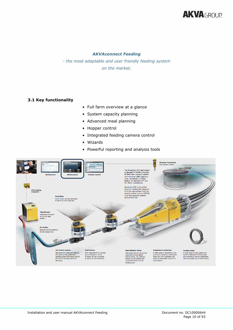
AKVAconnect Feeding
- the most adaptable and user friendly feeding system
on the market.
3.1 Key functionality
• Full farm overview at a glance
• System capacity planning
• Advanced meal planning
• Hopper control
• Integrated feeding camera control
• Wizards
• Powerful reporting and analysis tools

Page 11 of 93
Installation and user manual AKVAconnect Feeding Document no. DC10000644
4 Installation
AKVAconnect has to be installed both on the server PC and the
client PC(s). Server and client may be installed on the same PC,
however this is not recommended in order to avoid problems
with the feeding during any problems with the user PC (client).
The installation procedures for server and client PC are mostly
the same, besides for step 5.
AKVAconnect is downloaded from CD, USB-pen or from the
Internet, follow the instructions below:
1 Right click on the file AKVAconnect v2.7.exe and choose Open
2 Choose language (Norwegian, English or Spanish)
3 Read the information and click ‘Next’ to proceed or ‘Cancel’ to
cancel the installation

Page 12 of 93
Installation and user manual AKVAconnect Feeding Document no. DC10000644
4 Choose target folder, we recommend using the suggested
location, click ‘Next’
5 Choose Start menu folder, we recommend using the
suggested file, click ‘Next’
Page 13 of 93
Installation and user manual AKVAconnect Feeding Document no. DC10000644
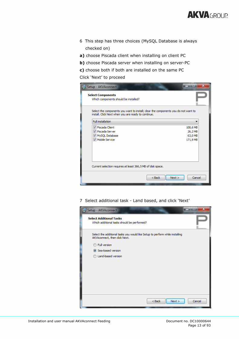
6 This step has three choices (MySQL Database is always
checked on)
a) choose Piscada client when installing on client PC
b) choose Piscada server when installing on server-PC
c) choose both if both are installed on the same PC
Click ‘Next’ to proceed
7 Select additional task - Land based, and click ‘Next’

Page 14 of 93
Installation and user manual AKVAconnect Feeding Document no. DC10000644
8 Click ‘Install’ to start the installation
9 Wait while the program is installed
Page 15 of 93
Installation and user manual AKVAconnect Feeding Document no. DC10000644
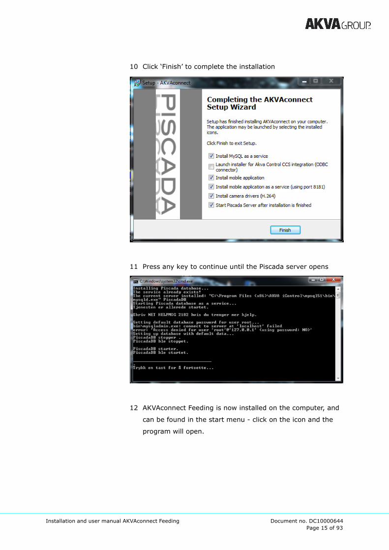
10 Click ‘Finish’ to complete the installation
11 Press any key to continue until the Piscada server opens
12 AKVAconnect Feeding is now installed on the computer, and
can be found in the start menu - click on the icon and the
program will open.

Page 16 of 93
Installation and user manual AKVAconnect Feeding Document no. DC10000644
5 License
In order to use AKVAconnect Feeding after AKVAconnect has
been installed, a valid license has to be inserted.
5.1 License request
Firstly, download the program (from CD, USB-pen or from the
Internet), and follow the instructions in chapter 4.
The Piscada-server will open when the program is installed.
Generating the license:
1 Click ‘File’
2 Click ‘Generate license information’
3 Enter the company name (1)
4 click Copy MAC to clipboard (2)
5 Close (3)
6 Open a new e-mail, type Ctrl+V (or right click and choose
Paste) and send this to AKVA group ASA.
Remember to include Your company name in this e-mail.
7 AKVA will then return a license code for you to install.
Page 17 of 93
Installation and user manual AKVAconnect Feeding Document no. DC10000644
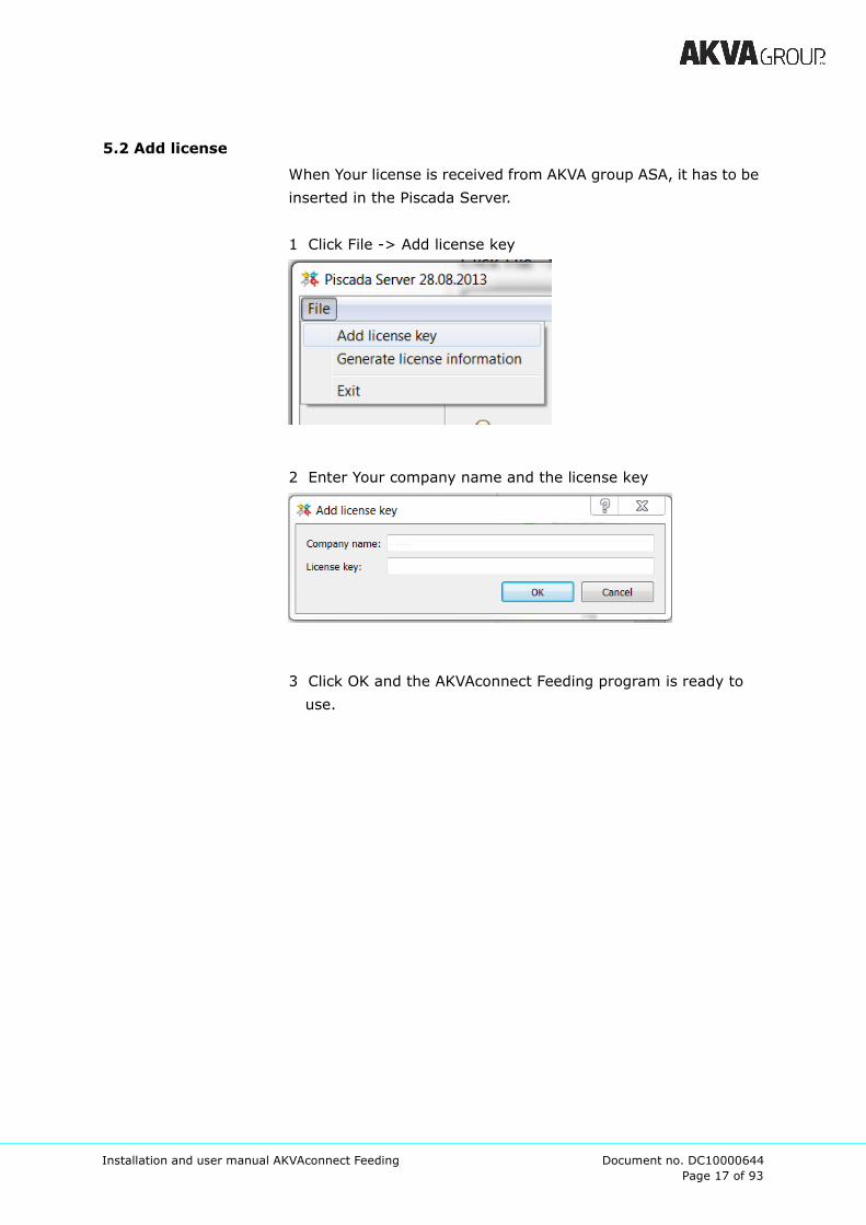
5.2 Add license
When Your license is received from AKVA group ASA, it has to be
inserted in the Piscada Server.
1 Click File -> Add license key
2 Enter Your company name and the license key
3 Click OK and the AKVAconnect Feeding program is ready to
use.

Page 18 of 93
Installation and user manual AKVAconnect Feeding Document no. DC10000644
6 The AKVAconnect menu
A menu line is located on top of the AKVAconnect window:
Shut down the program
Switches from/to full screen
Home, closes the open application/window to show the home
page as after log in
Switches back from the home page to the last process view
loaded.
Refresh the process view
Opens the settings window
Opens the tools sub menu ------------>
Opens the alarm log table
Opens the event log table
Opens the process views (multi-site overview)
When green, no un-acknowledged alarms exist, red if an alarm
has been raised
Page 19 of 93
Installation and user manual AKVAconnect Feeding Document no. DC10000644
7 Roles and users
When AKVAconnect is installed and a valid license is inserted,
open the AKVAconnect Feeding client from the start menu:
->
First, roles have to be defined/modified, thereafter add users
who are given different roles to decide access.
roles - different degrees of accesses, one role can be given to
several users
user - one user per employee or one for each degree of access,
every user has a role
Three different roles are already installed in the software. The
Technician has access to everything, and it is not necessary to
change anything here, technician has to have access to
everything.
Continue the installation, and get back to this point after process
view and feed settings are defined (after chapter 10). Then,
accesses for Farmer, Site manager and perhaps other roles
desired to the site, may be defined.
We recommend that Site manager have access to change
system settings, and that Farmer have access to daily use.
Page 20 of 93
Installation and user manual AKVAconnect Feeding Document no. DC10000644
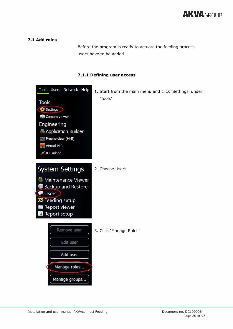
7.1 Add roles
Before the program is ready to actuate the feeding process,
users have to be added.
7.1.1 Defining user access
1. Start from the main menu and click ‘Settings’ under
‘Tools’
2. Choose Users
3. Click ‘Manage Roles’
Page 21 of 93
Installation and user manual AKVAconnect Feeding Document no. DC10000644
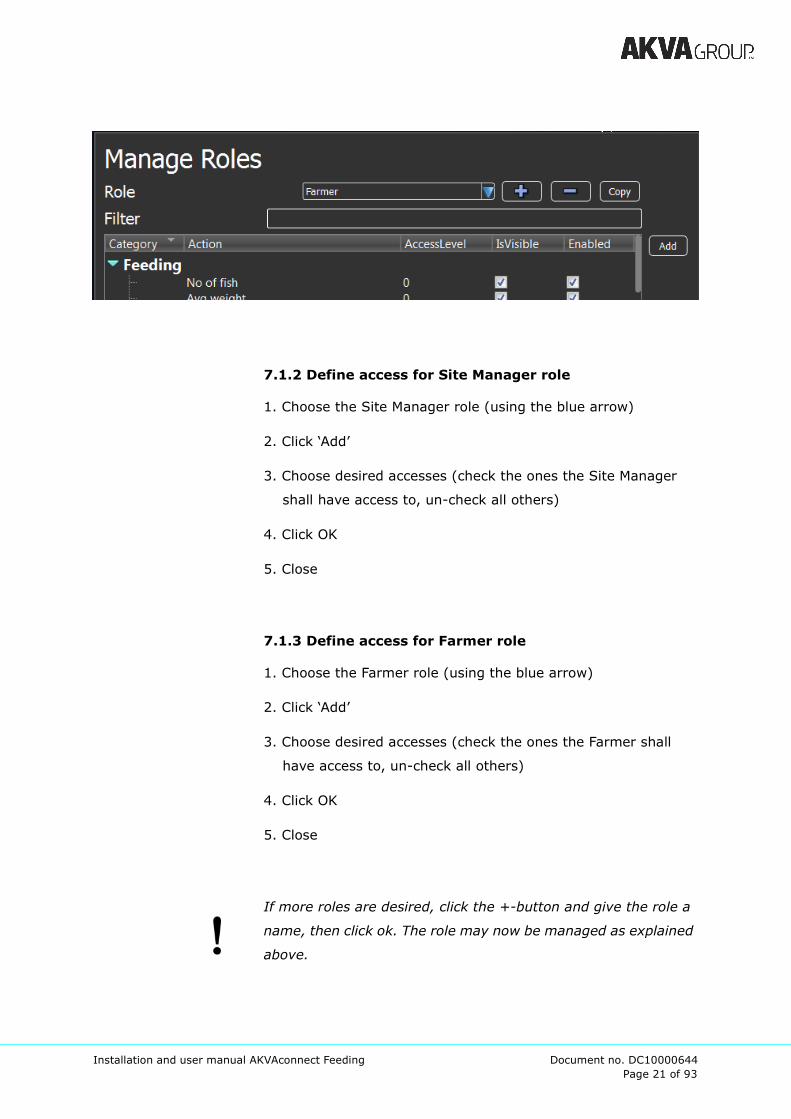
7.1.2 Define access for Site Manager role
1. Choose the Site Manager role (using the blue arrow)
2. Click ‘Add’
3. Choose desired accesses (check the ones the Site Manager
shall have access to, un-check all others)
4. Click OK
5. Close
7.1.3 Define access for Farmer role
1. Choose the Farmer role (using the blue arrow)
2. Click ‘Add’
3. Choose desired accesses (check the ones the Farmer shall
have access to, un-check all others)
4. Click OK
5. Close
If more roles are desired, click the +-button and give the role a
name, then click ok. The role may now be managed as explained
above.
Page 22 of 93
Installation and user manual AKVAconnect Feeding Document no. DC10000644
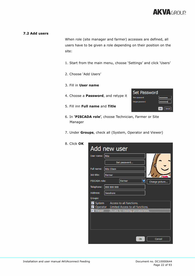
7.2 Add users
When role (site manager and farmer) accesses are defined, all
users have to be given a role depending on their position on the
site:
1. Start from the main menu, choose ‘Settings’ and click ‘Users’
2. Choose ‘Add Users’
3. Fill in User name
4. Choose a Password, and retype it
5. Fill inn Full name and Title
6. In ‘PISCADA role’, choose Technician, Farmer or Site
Manager
7. Under Groups, check all (System, Operator and Viewer)
8. Click OK

Page 23 of 93
Installation and user manual AKVAconnect Feeding Document no. DC10000644
7.3 Hints
We recommend that every employee/user of the AKVAconnect
Feeding software have their own user, with their own personal
user ID and password.
All users must remember to log off when they are finished using
the AKVAconnect Feeding software. Knowing who has done what
will make managing the site easier.
Page 24 of 93
Installation and user manual AKVAconnect Feeding Document no. DC10000644
8 Application builder
The applications in AKVAconnect Feeding is built according to
how the physical installation is set up. To connect the program
with the physical components, use an overview over ILCs (PLCs
with I/O where all control signals are connected). These have to
be given unique IP addresses using ipassign.exe when they are
connected to the system.
State these IP addresses when new applications are set up, see
chapter 8.1. The IP address may be set later if necessary.
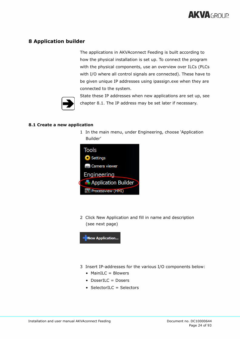
8.1 Create a new application
1 In the main menu, under Engineering, choose ‘Application
Builder’
2 Click New Application and fill in name and description
(see next page)
3 Insert IP-addresses for the various I/O components below:
• MainILC = Blowers
• DoserILC = Dosers
• SelectorILC = Selectors

Page 25 of 93
Installation and user manual AKVAconnect Feeding Document no. DC10000644
4 If there are more than one piece of
each component:
- Click on the correct type
- Choose ‘Add’
- Type the current IP address for the
added I/O components
- Type a name that separates the new
component from other similar
components (however, use
systematic names that are easily
recognized and understood)
5 Click OK when all components are added.
6 When the application has been given a name, and the
I/O components have been given correct IP addresses,
this page appears:
The white box under the Line-name (here: “Feed Line A”)
represents the feed line control area, this is where all
components are placed to set up the feed line control.
Page 26 of 93
Installation and user manual AKVAconnect Feeding Document no. DC10000644
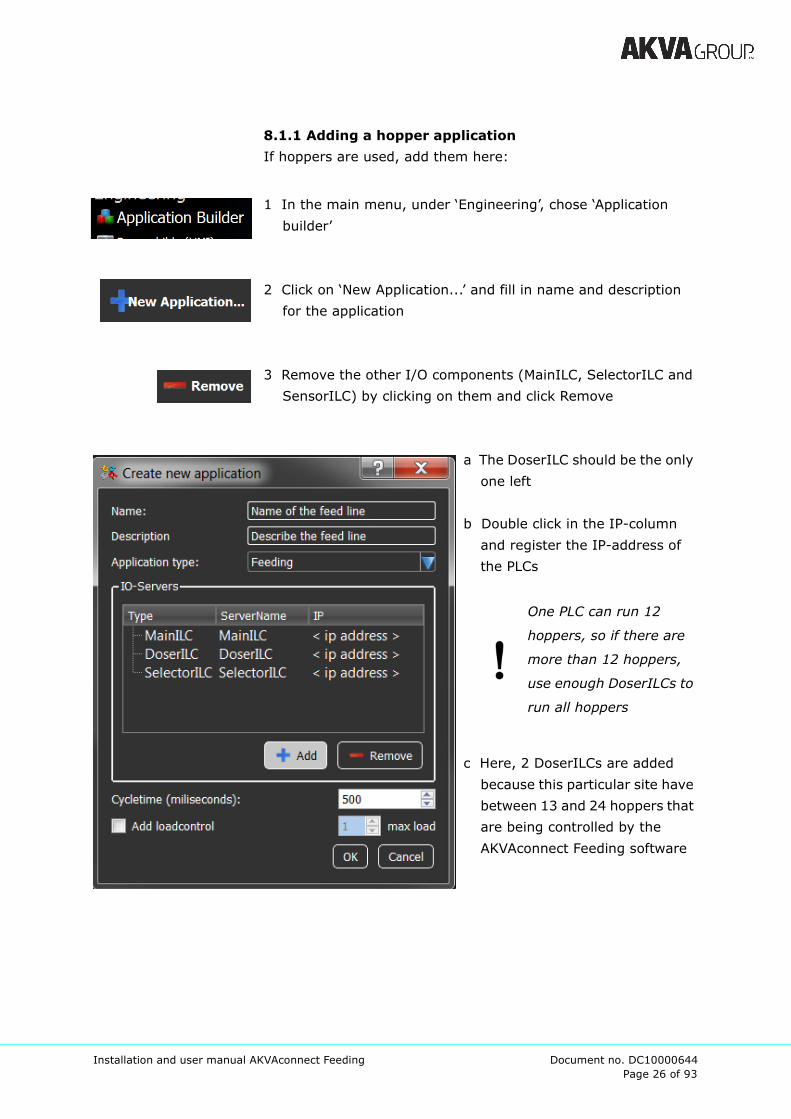
8.1.1 Adding a hopper application
If hoppers are used, add them here:
1 In the main menu, under ‘Engineering’, chose ‘Application
builder’
2 Click on ‘New Application...’ and fill in name and description
for the application
3 Remove the other I/O components (MainILC, SelectorILC and
SensorILC) by clicking on them and click Remove
a The DoserILC should be the only
one left
b Double click in the IP-column
and register the IP-address of
the PLCs
One PLC can run 12
hoppers, so if there are
more than 12 hoppers,
use enough DoserILCs to
run all hoppers
c Here, 2 DoserILCs are added
because this particular site have
between 13 and 24 hoppers that
are being controlled by the
AKVAconnect Feeding software
Page 27 of 93
Installation and user manual AKVAconnect Feeding Document no. DC10000644
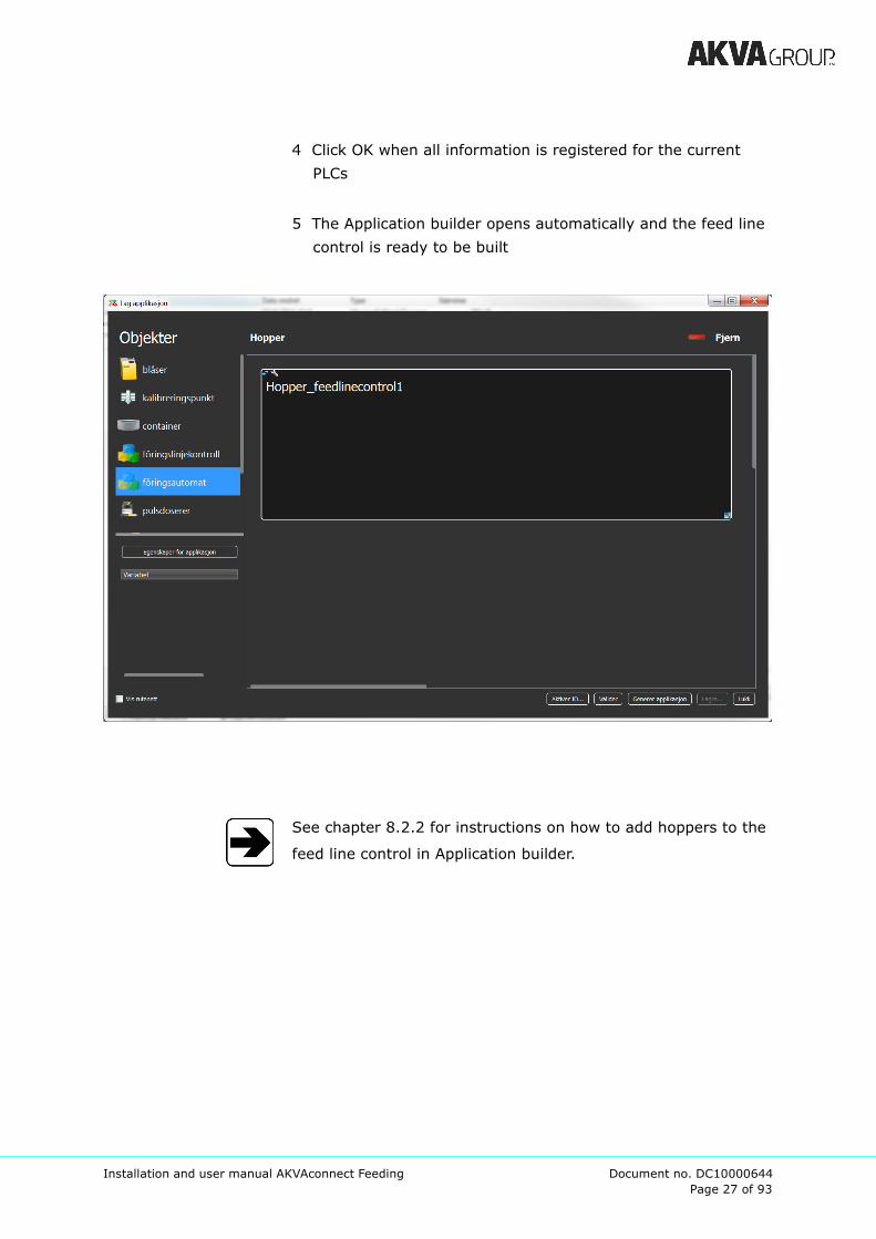
4 Click OK when all information is registered for the current
PLCs
5 The Application builder opens automatically and the feed line
control is ready to be built
See chapter 8.2.2 for instructions on how to add hoppers to the
feed line control in Application builder.
Page 28 of 93
Installation and user manual AKVAconnect Feeding Document no. DC10000644
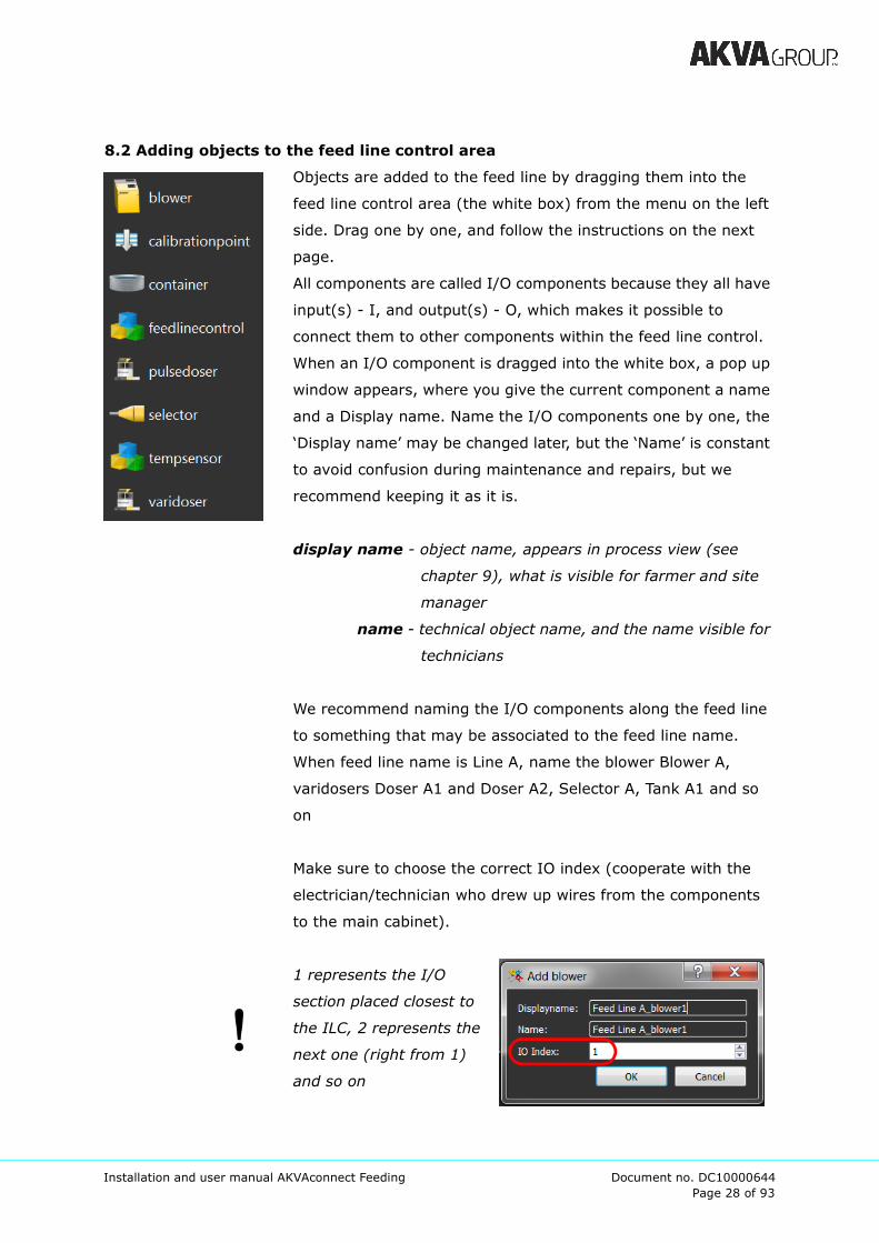
8.2 Adding objects to the feed line control area
Objects are added to the feed line by dragging them into the
feed line control area (the white box) from the menu on the left
side. Drag one by one, and follow the instructions on the next
page.
All components are called I/O components because they all have
input(s) - I, and output(s) - O, which makes it possible to
connect them to other components within the feed line control.
When an I/O component is dragged into the white box, a pop up
window appears, where you give the current component a name
and a Display name. Name the I/O components one by one, the
‘Display name’ may be changed later, but the ‘Name’ is constant
to avoid confusion during maintenance and repairs, but we
recommend keeping it as it is.
display name - object name, appears in process view (see
chapter 9), what is visible for farmer and site
manager
name - technical object name, and the name visible for
technicians
We recommend naming the I/O components along the feed line
to something that may be associated to the feed line name.
When feed line name is Line A, name the blower Blower A,
varidosers Doser A1 and Doser A2, Selector A, Tank A1 and so
on
Make sure to choose the correct IO index (cooperate with the
electrician/technician who drew up wires from the components
to the main cabinet).
1 represents the I/O
section placed closest to
the ILC, 2 represents the
next one (right from 1)
and so on
Page 29 of 93
Installation and user manual AKVAconnect Feeding Document no. DC10000644
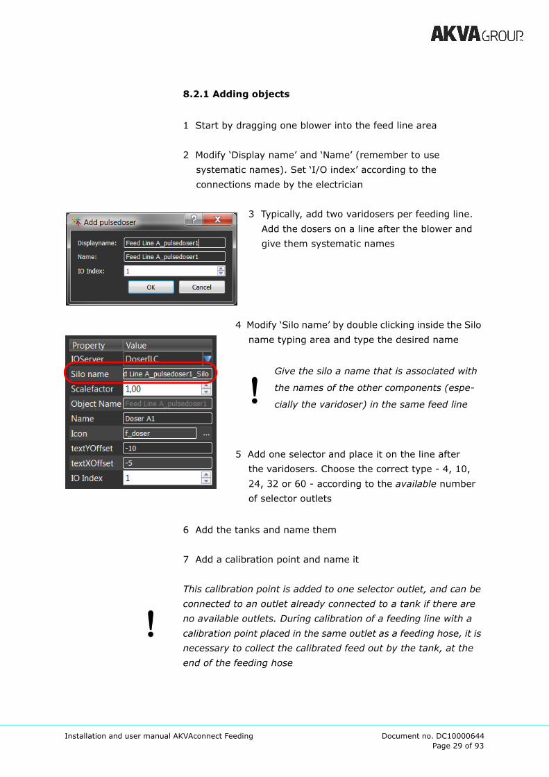
8.2.1 Adding objects
1 Start by dragging one blower into the feed line area
2 Modify ‘Display name’ and ‘Name’ (remember to use
systematic names). Set ‘I/O index’ according to the
connections made by the electrician
3 Typically, add two varidosers per feeding line.
Add the dosers on a line after the blower and
give them systematic names
4 Modify ‘Silo name’ by double clicking inside the Silo
name typing area and type the desired name
Give the silo a name that is associated with
the names of the other components (espe-
cially the varidoser) in the same feed line
5 Add one selector and place it on the line after
the varidosers. Choose the correct type - 4, 10,
24, 32 or 60 - according to the available number
of selector outlets
6 Add the tanks and name them
7 Add a calibration point and name it
This calibration point is added to one selector outlet, and can be
connected to an outlet already connected to a tank if there are
no available outlets. During calibration of a feeding line with a
calibration point placed in the same outlet as a feeding hose, it is
necessary to collect the calibrated feed out by the tank, at the
end of the feeding hose
Page 30 of 93
Installation and user manual AKVAconnect Feeding Document no. DC10000644
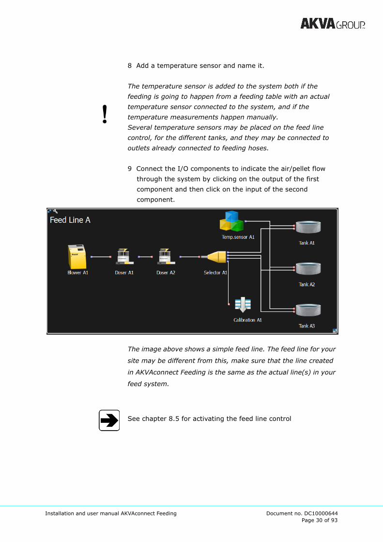
8 Add a temperature sensor and name it.
The temperature sensor is added to the system both if the
feeding is going to happen from a feeding table with an actual
temperature sensor connected to the system, and if the
temperature measurements happen manually.
Several temperature sensors may be placed on the feed line
control, for the different tanks, and they may be connected to
outlets already connected to feeding hoses.
9 Connect the I/O components to indicate the air/pellet flow
through the system by clicking on the output of the first
component and then click on the input of the second
component.
The image above shows a simple feed line. The feed line for your
site may be different from this, make sure that the line created
in AKVAconnect Feeding is the same as the actual line(s) in your
feed system.
See chapter 8.5 for activating the feed line control
Page 31 of 93
Installation and user manual AKVAconnect Feeding Document no. DC10000644
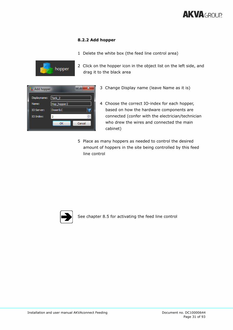
8.2.2 Add hopper
1 Delete the white box (the feed line control area)
2 Click on the hopper icon in the object list on the left side, and
drag it to the black area
3 Change Display name (leave Name as it is)
4 Choose the correct IO-index for each hopper,
based on how the hardware components are
connected (confer with the electrician/technician
who drew the wires and connected the main
cabinet)
5 Place as many hoppers as needed to control the desired
amount of hoppers in the site being controlled by this feed
line control
See chapter 8.5 for activating the feed line control

Page 32 of 93
Installation and user manual AKVAconnect Feeding Document no. DC10000644
8.2.3 Removing objects
If an object is added that should not be in the feed line, this may
be removed after it is added. Click on the symbol, and a dotted
frame will appear around the object. Click ‘Remove’ in the upper
right corner of the window.
8.2.4 Removing connections
If a mistake is made during the connection process,
click on the connection line so that it appears as a
dotted line (see line between Selector B and Tank B3
in the image under), and click ‘Remove’ in the upper
right side.
Page 33 of 93
Installation and user manual AKVAconnect Feeding Document no. DC10000644
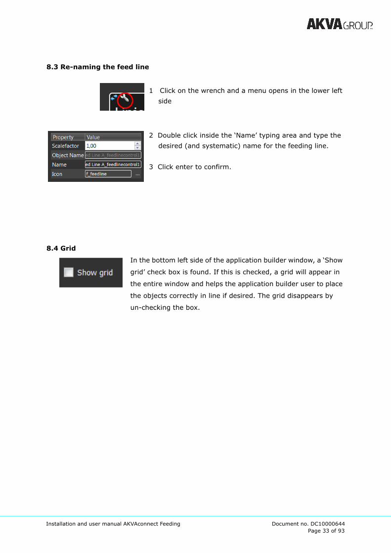
8.3 Re-naming the feed line
1 Click on the wrench and a menu opens in the lower left
side
2 Double click inside the ‘Name’ typing area and type the
desired (and systematic) name for the feeding line.
3 Click enter to confirm.
8.4 Grid
In the bottom left side of the application builder window, a ‘Show
grid’ check box is found. If this is checked, a grid will appear in
the entire window and helps the application builder user to place
the objects correctly in line if desired. The grid disappears by
un-checking the box.
Page 34 of 93
Installation and user manual AKVAconnect Feeding Document no. DC10000644
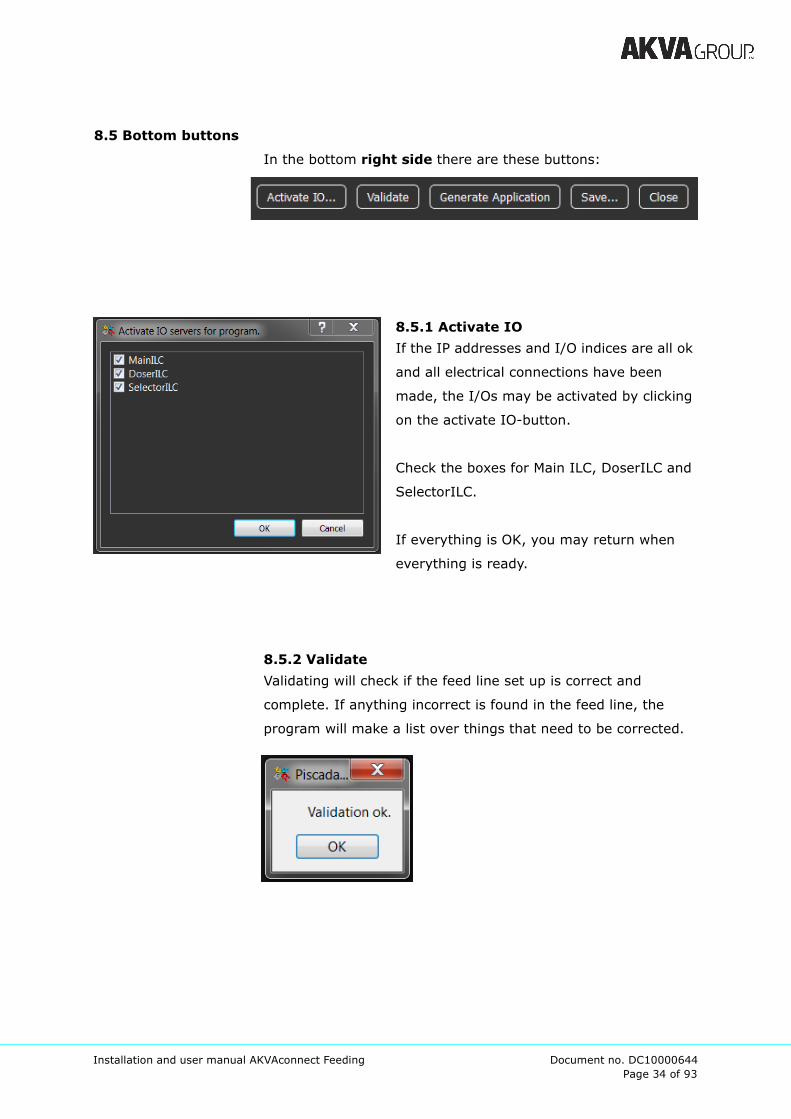
8.5 Bottom buttons
In the bottom right side there are these buttons:
8.5.1 Activate IO
If the IP addresses and I/O indices are all ok
and all electrical connections have been
made, the I/Os may be activated by clicking
on the activate IO-button.
Check the boxes for Main ILC, DoserILC and
SelectorILC.
If everything is OK, you may return when
everything is ready.
8.5.2 Validate
Validating will check if the feed line set up is correct and
complete. If anything incorrect is found in the feed line, the
program will make a list over things that need to be corrected.

Page 35 of 93
Installation and user manual AKVAconnect Feeding Document no. DC10000644
8.5.3 Generate Application
To be able to use the feed line application that is built, it needs
to be “activated” or Generated. This is programmed to happen
when Generate Application button is clicked on, and is shown to
the user by green process progression indicator line. When the
line disappears, the generating process is done and it is possible
to proceed with the set up process.
8.5.4 Save
We recommend saving the work regularly to avoid losing any
work in case something should happen to any of the PCs.
8.5.5 Close
Use this button when the window should be closed. Remember
to save the work before closing.
Page 36 of 93
Installation and user manual AKVAconnect Feeding Document no. DC10000644
8.6 Various feed systems
It is possible to feed one tank through two different pipes, either
from one selector (sequential feeding) or from two different feed
lines (parallel feeding).
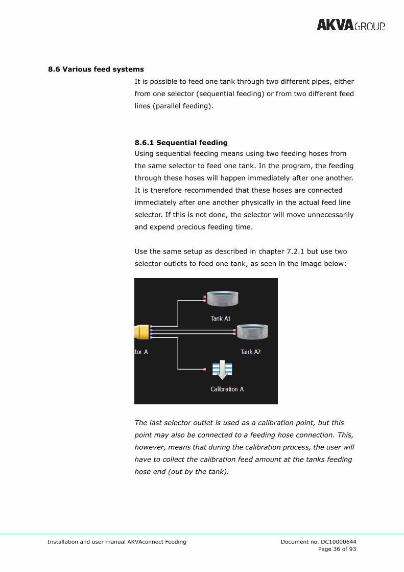
8.6.1 Sequential feeding
Using sequential feeding means using two feeding hoses from
the same selector to feed one tank. In the program, the feeding
through these hoses will happen immediately after one another.
It is therefore recommended that these hoses are connected
immediately after one another physically in the actual feed line
selector. If this is not done, the selector will move unnecessarily
and expend precious feeding time.
Use the same setup as described in chapter 7.2.1 but use two
selector outlets to feed one tank, as seen in the image below:
The last selector outlet is used as a calibration point, but this
point may also be connected to a feeding hose connection. This,
however, means that during the calibration process, the user will
have to collect the calibration feed amount at the tanks feeding
hose end (out by the tank).
Page 37 of 93
Installation and user manual AKVAconnect Feeding Document no. DC10000644
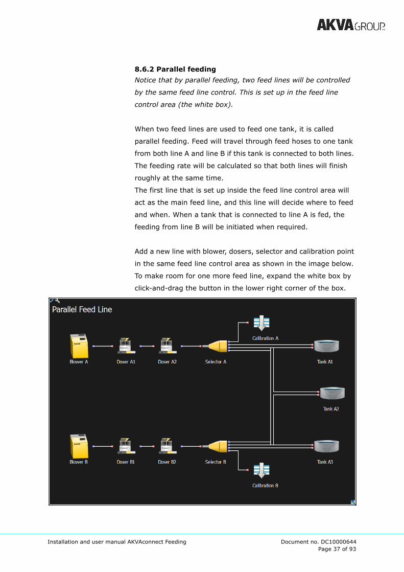
8.6.2 Parallel feeding
Notice that by parallel feeding, two feed lines will be controlled
by the same feed line control. This is set up in the feed line
control area (the white box).
When two feed lines are used to feed one tank, it is called
parallel feeding. Feed will travel through feed hoses to one tank
from both line A and line B if this tank is connected to both lines.
The feeding rate will be calculated so that both lines will finish
roughly at the same time.
The first line that is set up inside the feed line control area will
act as the main feed line, and this line will decide where to feed
and when. When a tank that is connected to line A is fed, the
feeding from line B will be initiated when required.
Add a new line with blower, dosers, selector and calibration point
in the same feed line control area as shown in the image below.
To make room for one more feed line, expand the white box by
click-and-drag the button in the lower right corner of the box.
Page 38 of 93
Installation and user manual AKVAconnect Feeding Document no. DC10000644
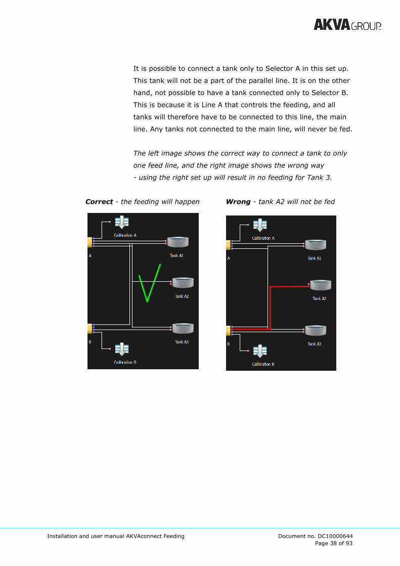
It is possible to connect a tank only to Selector A in this set up.
This tank will not be a part of the parallel line. It is on the other
hand, not possible to have a tank connected only to Selector B.
This is because it is Line A that controls the feeding, and all
tanks will therefore have to be connected to this line, the main
line. Any tanks not connected to the main line, will never be fed.
The left image shows the correct way to connect a tank to only
one feed line, and the right image shows the wrong way
- using the right set up will result in no feeding for Tank 3.
Correct - the feeding will happen Wrong - tank A2 will not be fed
Page 39 of 93
Installation and user manual AKVAconnect Feeding Document no. DC10000644
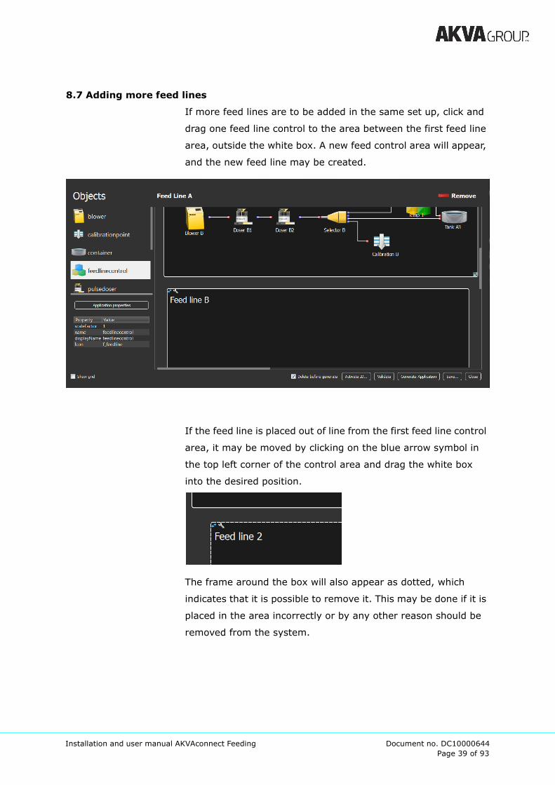
8.7 Adding more feed lines
If more feed lines are to be added in the same set up, click and
drag one feed line control to the area between the first feed line
area, outside the white box. A new feed control area will appear,
and the new feed line may be created.
If the feed line is placed out of line from the first feed line control
area, it may be moved by clicking on the blue arrow symbol in
the top left corner of the control area and drag the white box
into the desired position.
The frame around the box will also appear as dotted, which
indicates that it is possible to remove it. This may be done if it is
placed in the area incorrectly or by any other reason should be
removed from the system.
Page 40 of 93
Installation and user manual AKVAconnect Feeding Document no. DC10000644
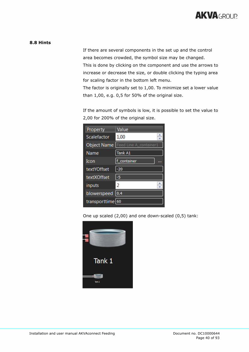
8.8 Hints
If there are several components in the set up and the control
area becomes crowded, the symbol size may be changed.
This is done by clicking on the component and use the arrows to
increase or decrease the size, or double clicking the typing area
for scaling factor in the bottom left menu.
The factor is originally set to 1,00. To minimize set a lower value
than 1,00, e.g. 0,5 for 50% of the original size.
If the amount of symbols is low, it is possible to set the value to
2,00 for 200% of the original size.
One up scaled (2,00) and one down-scaled (0,5) tank:

Page 41 of 93
Installation and user manual AKVAconnect Feeding Document no. DC10000644
9 Set up process view
Process view is established from the main menu, and
information such as name, description, screen resolution and
access control is set here. When all information is set, the pro-
cess view may be opened.
Process view is set up by adding symbols for every component
in the feed line in the site that are being controlled with AKVA-
connect Feeding (like the feed line control set up in application
builder).
Examples of objects are tanks with belonging silos, hoppers,
feed line controls, sensors and clock.
The symbol sizes are adjusted to the total number of compo-
nents in the feed line, the size of the site being controlled by this
particular process view - the more objects the smaller sized
symbols. Size and appearance are set when the symbol is added
to the process view window, but may easily be changed later by
using the process view edit-mode.
Place symbols in the same order as they are placed in the site
location to simplify the use.
Page 42 of 93
Installation and user manual AKVAconnect Feeding Document no. DC10000644
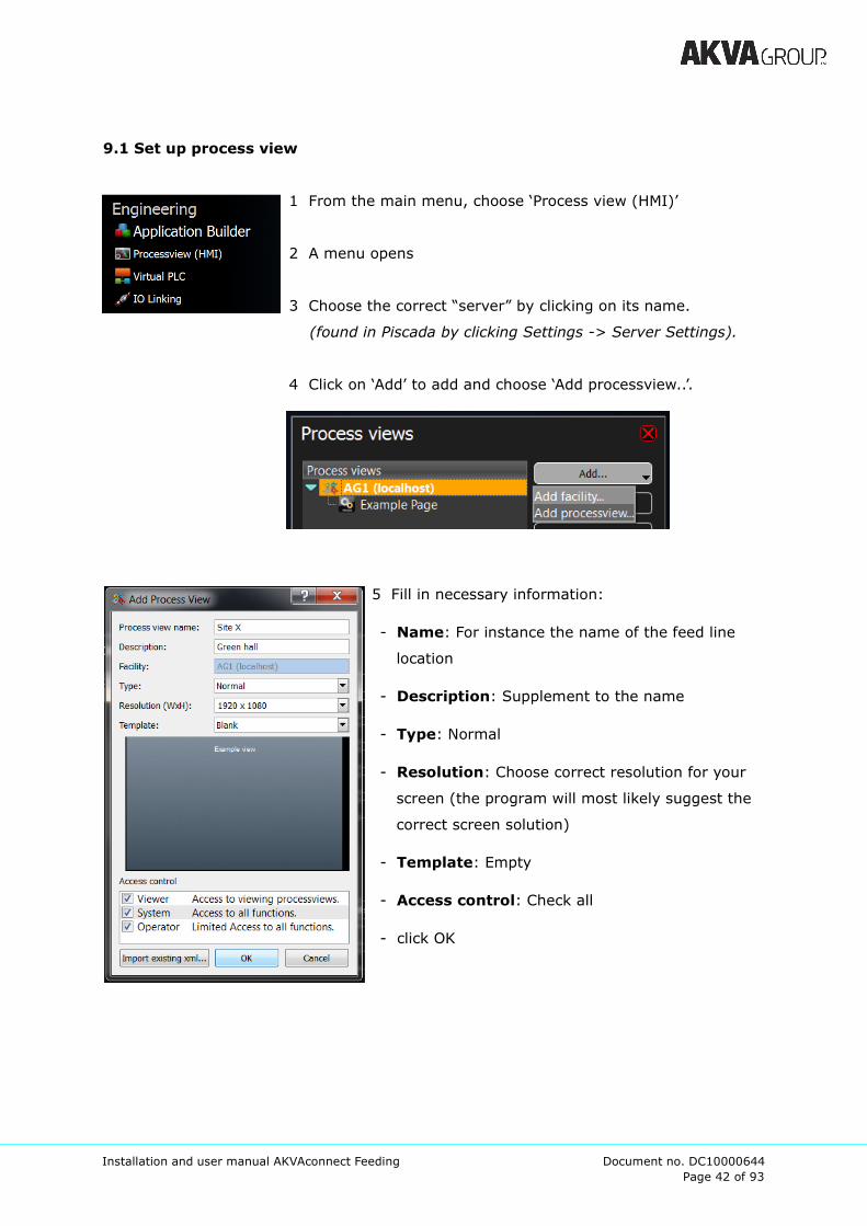
9.1 Set up process view
1 From the main menu, choose ‘Process view (HMI)’
2 A menu opens
3 Choose the correct “server” by clicking on its name.
(found in Piscada by clicking Settings -> Server Settings).
4 Click on ‘Add’ to add and choose ‘Add processview..’.
5 Fill in necessary information:
- Name: For instance the name of the feed line
location
- Description: Supplement to the name
- Type: Normal
- Resolution: Choose correct resolution for your
screen (the program will most likely suggest the
correct screen solution)
- Template: Empty
- Access control: Check all
- click OK
Page 43 of 93
Installation and user manual AKVAconnect Feeding Document no. DC10000644
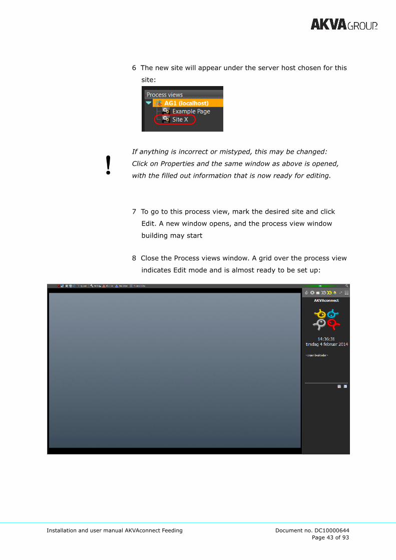
6 The new site will appear under the server host chosen for this
site:
If anything is incorrect or mistyped, this may be changed:
Click on Properties and the same window as above is opened,
with the filled out information that is now ready for editing.
7 To go to this process view, mark the desired site and click
Edit. A new window opens, and the process view window
building may start
8 Close the Process views window. A grid over the process view
indicates Edit mode and is almost ready to be set up:
Page 44 of 93
Installation and user manual AKVAconnect Feeding Document no. DC10000644
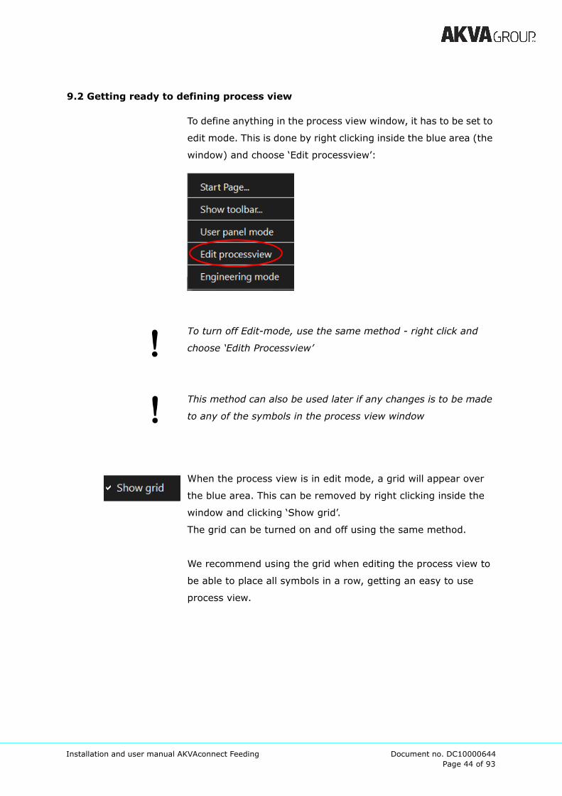
9.2 Getting ready to defining process view
To define anything in the process view window, it has to be set to
edit mode. This is done by right clicking inside the blue area (the
window) and choose ‘Edit processview’:
To turn off Edit-mode, use the same method - right click and
choose ‘Edith Processview’
This method can also be used later if any changes is to be made
to any of the symbols in the process view window
When the process view is in edit mode, a grid will appear over
the blue area. This can be removed by right clicking inside the
window and clicking ‘Show grid’.
The grid can be turned on and off using the same method.
We recommend using the grid when editing the process view to
be able to place all symbols in a row, getting an easy to use
process view.

Page 45 of 93
Installation and user manual AKVAconnect Feeding Document no. DC10000644
The Process elements menu will also appear when the process
view window opens. This is a collection of all elements that may
be used in the process view.
For AKVAcontrol Feeding, there are fitted elements, to see them:
1 Check ‘Show general
settings’ (red ring)
2 Leave ‘Type’ to ‘Normal’
3 Check ‘Show device area by
default’ (below ‘Type’, yellow
ring)
4 Click on ‘All elements’
5 Click on Company Adjusted-symbol and all elements usable in
AKVAconnect Feeding will appear.
Adjust the ‘Process image elements’ window by using the
click-and-drag method in the bottom right corner symbol in the
‘Process view items’ window. More objects and components will
then appear.

Page 46 of 93
Installation and user manual AKVAconnect Feeding Document no. DC10000644
9.3 Define the process view
9.3.1 Add background
If two or more sites are being controlled by the same AKVAcon-
trol Feeding module, we recommend using different backgrounds
for each site, so that they can easily be told apart.
The different symbols are placed on this background, tanks,
silos, hoppers, feed line controls, sensors as well as various
extra functions, such as a clock.
It is possible to use any picture as background in the process
view window. We recommend using an image that represents
the site, either an overview photo or a model picture of the site.
The image used has to be either .png, .jpg or .gif.
The image will appear as background for the process view,
therefore it is useful to use an image that fits the screen.
Procedure:
1 Click ‘Edit background’ in the Process image element (make
sure to check the box for ‘Show general settings’)
2 Click ‘Add’ if the image is not already added, then browse for
the desired image
3 ‘Open’ -> the image is copied into the Symbol overview
4 Mark the desired image
5 Click ‘Select’
An example on how the
background may look
Page 47 of 93
Installation and user manual AKVAconnect Feeding Document no. DC10000644
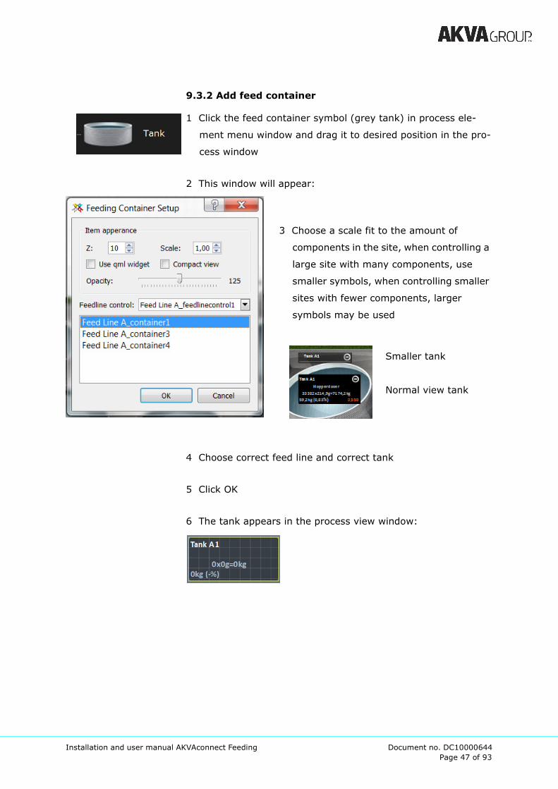
9.3.2 Add feed container
1 Click the feed container symbol (grey tank) in process ele-
ment menu window and drag it to desired position in the pro-
cess window
2 This window will appear:
3 Choose a scale fit to the amount of
components in the site, when controlling a
large site with many components, use
smaller symbols, when controlling smaller
sites with fewer components, larger
symbols may be used
Smaller tank
Normal view tank
4 Choose correct feed line and correct tank
5 Click OK
6 The tank appears in the process view window:

Page 48 of 93
Installation and user manual AKVAconnect Feeding Document no. DC10000644
9.3.3 Feed line control
1 Click on the feedline control symbol (yellow symbol) and drag
it to desired position
2 This window will appear:
3 Choose a scale fit to the amount of components in the site,
when controlling a large site with many components, use
smaller symbols, when controlling smaller sites with fewer
components, larger symbols may be used
4 Choose desired amount of tanks visible in this feed line
control. If the site has several feed line controls, it will be
advantageous to use fewer tanks showing in the symbol. We
recommend showing 3 tanks when there is space for that.
It is always possible to view all tanks, although not at the same
time. Use the green arrows in the middle of the feed line control
symbol to navigate from tank to tank. The symbol between the
arrows is used for automatic rotation, and will always show the
tank that is feeding at the moment.
Page 49 of 93
Installation and user manual AKVAconnect Feeding Document no. DC10000644
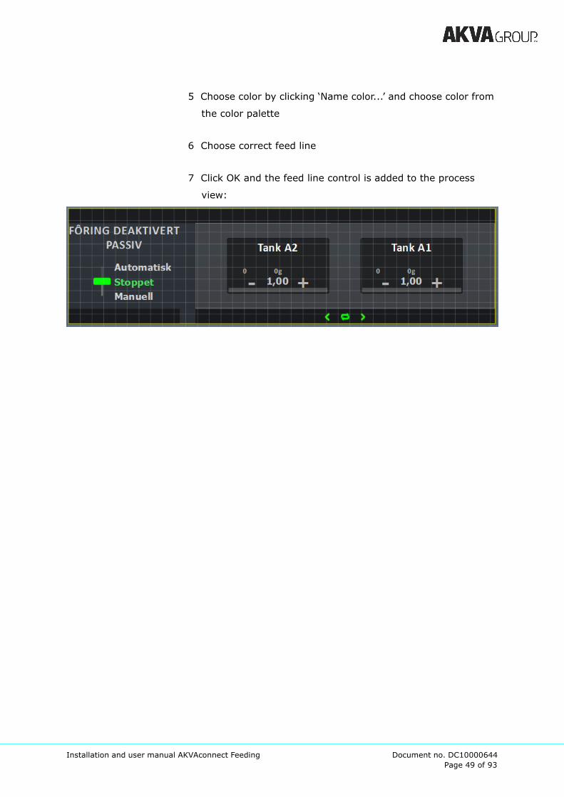
5 Choose color by clicking ‘Name color...’ and choose color from
the color palette
6 Choose correct feed line
7 Click OK and the feed line control is added to the process
view:
Page 50 of 93
Installation and user manual AKVAconnect Feeding Document no. DC10000644
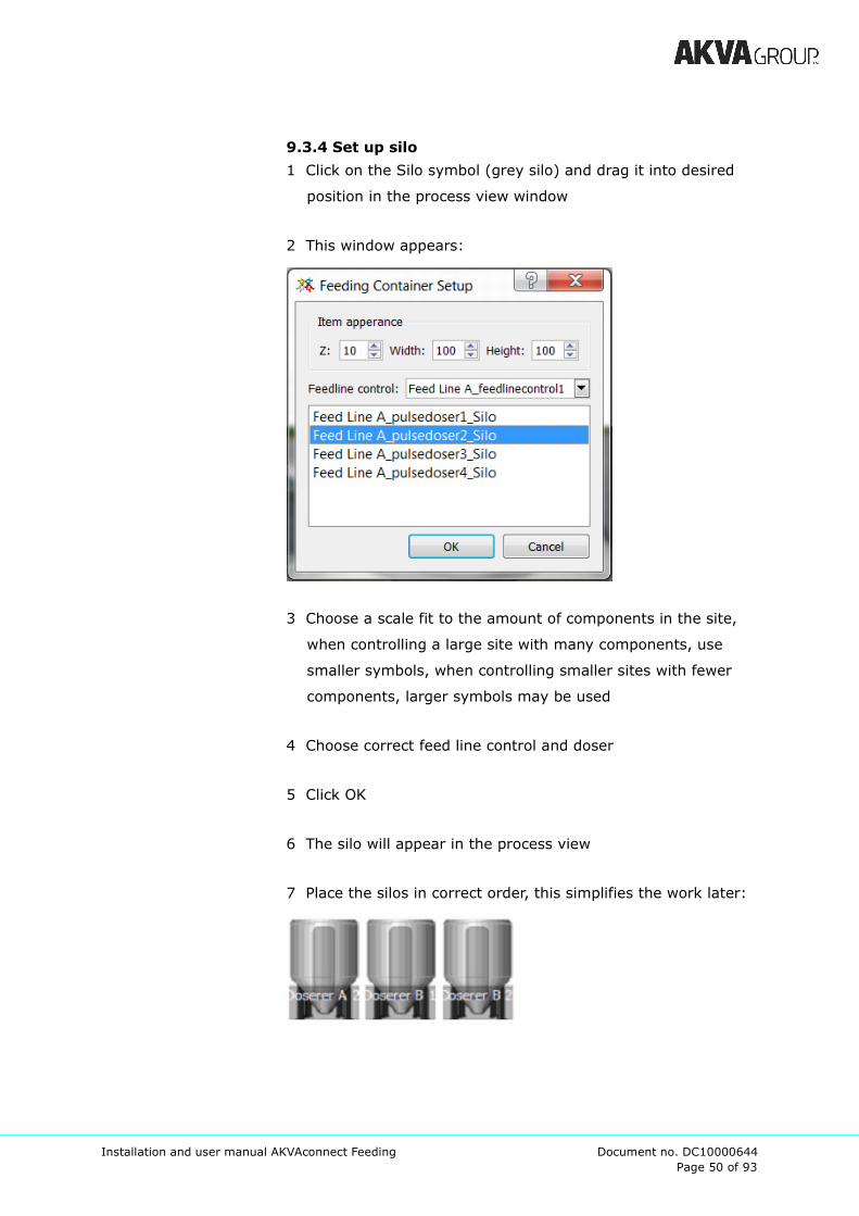
9.3.4 Set up silo
1 Click on the Silo symbol (grey silo) and drag it into desired
position in the process view window
2 This window appears:
3 Choose a scale fit to the amount of components in the site,
when controlling a large site with many components, use
smaller symbols, when controlling smaller sites with fewer
components, larger symbols may be used
4 Choose correct feed line control and doser
5 Click OK
6 The silo will appear in the process view
7 Place the silos in correct order, this simplifies the work later:
Page 51 of 93
Installation and user manual AKVAconnect Feeding Document no. DC10000644
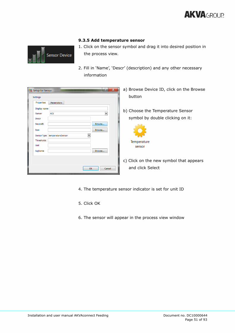
9.3.5 Add temperature sensor
1. Click on the sensor symbol and drag it into desired position in
the process view.
2. Fill in ‘Name’, ‘Descr’ (description) and any other necessary
information
a) Browse Device ID, click on the Browse
button
b) Choose the Temperature Sensor
symbol by double clicking on it:
c) Click on the new symbol that appears
and click Select
4. The temperature sensor indicator is set for unit ID
5. Click OK
6. The sensor will appear in the process view window
Page 52 of 93
Installation and user manual AKVAconnect Feeding Document no. DC10000644
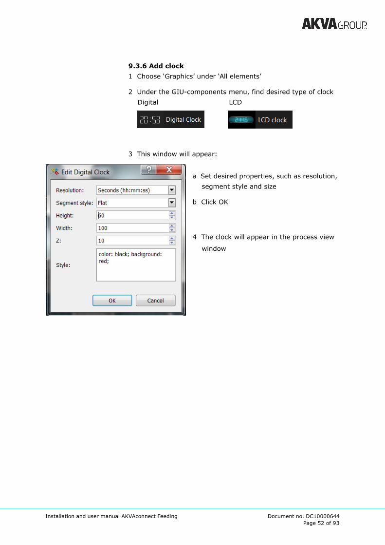
9.3.6 Add clock
1 Choose ‘Graphics’ under ‘All elements’
2 Under the GIU-components menu, find desired type of clock
Digital LCD
3 This window will appear:
a Set desired properties, such as resolution,
segment style and size
b Click OK
4 The clock will appear in the process view
window

Page 53 of 93
Installation and user manual AKVAconnect Feeding Document no. DC10000644
9.3.7 Add hopper
1 Click on the feed container symbol (gray tank) and drag it to
desired position in the process view window
2 This window will appear:
a Choose a scale fit to the amount of
components in the site, when controlling a
large site with many components, use
smaller symbols, when controlling smaller
sites with fewer components, larger
symbols may be used
Smaller tank
Normal view tank
b Check for Hopper
c Choose correct feed line coordinator, tank
d Choose correct hopper
3 Click OK
4 The hopper will appear in the process view window.

Page 54 of 93
Installation and user manual AKVAconnect Feeding Document no. DC10000644
9.2.8 Hints
If the process view window has been closed for any reason, it
may be reopened by exiting and re-entering the edit mode.
Right click in the process view window and click on
Edit processview
Page 55 of 93
Installation and user manual AKVAconnect Feeding Document no. DC10000644
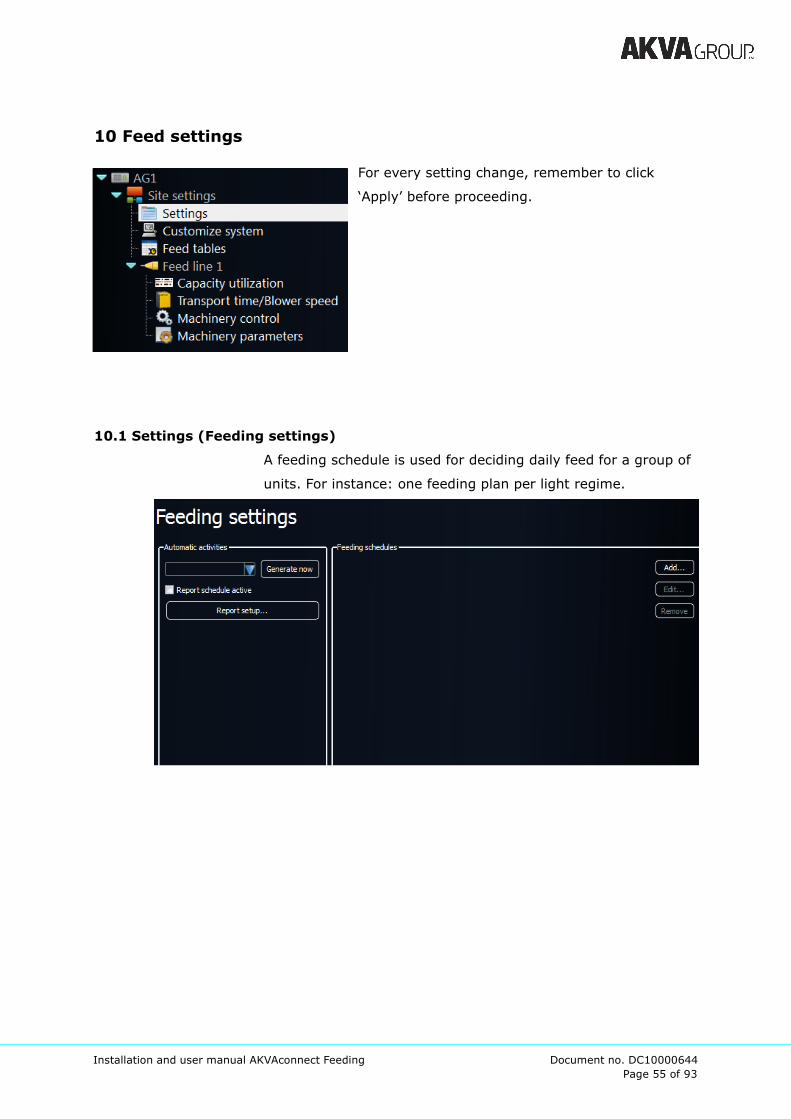
10 Feed settings
For every setting change, remember to click
‘Apply’ before proceeding.
10.1 Settings (Feeding settings)
A feeding schedule is used for deciding daily feed for a group of
units. For instance: one feeding plan per light regime.
Page 56 of 93
Installation and user manual AKVAconnect Feeding Document no. DC10000644
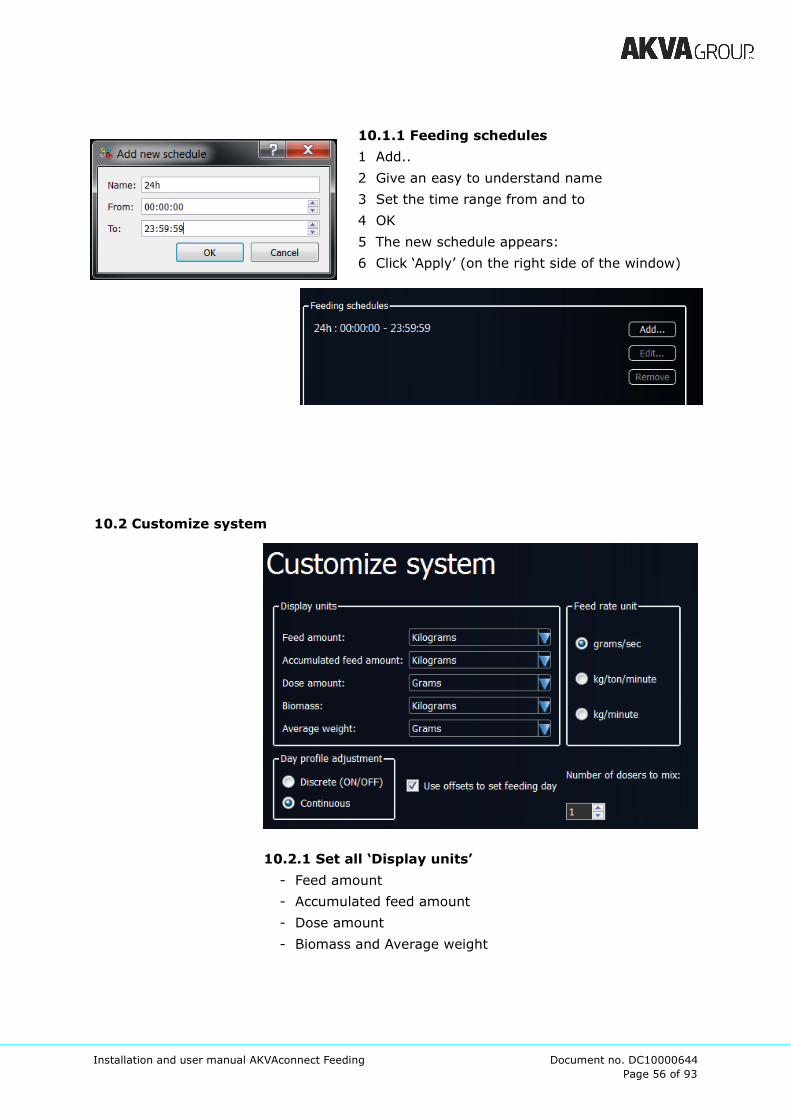
10.1.1 Feeding schedules
1 Add..
2 Give an easy to understand name
3 Set the time range from and to
4 OK
5 The new schedule appears:
6 Click ‘Apply’ (on the right side of the window)
10.2 Customize system
10.2.1 Set all ‘Display units’
- Feed amount
- Accumulated feed amount
- Dose amount
- Biomass and Average weight

Page 57 of 93
Installation and user manual AKVAconnect Feeding Document no. DC10000644
10.2.2 Feed rate unit decides how to indicate the feed
rate:
- grams/sec = Grams of feed per second
- kg/ton/minute = kg of feed per ton of fish per minute
(will increase as the fish grows)
- kg/minute = kg of feed per minute
10.2.3 Day profile adjustment:
Indicates whether there should be varied doses (continuous)
during the day, or if they should not be varied (Discrete ON/
OFF). (See chapter 11.2.9 to see visuals of these profile adjust-
ments.)
10.2.4 Use offsets to set feeding day
If individual settings are desired for each tank, here is a
possibility to set an offset for the single tanks. Leaving this
unchecked, offset may not be set.

Page 58 of 93
Installation and user manual AKVAconnect Feeding Document no. DC10000644
10.3 Feed tables
A standard feed table is found here.
10.3.1 This default table may be edited to fit each
tank.
1 Click on the tank in Process view
(Edit Processview = grid on)
2 Choose ‘Feeding’
3 (choose ‘Amount calc mode: Feed tables’ if this is not
set before)
4 Choose desired Feed table name (there will only be
one choice if only the standard table is set)
5 Increase or decrease the Table adjustment so that the
table is suited the actual tank. Over 1.0 means
increasing the feed, below 1.0 means lowering the
feed amount according to the chosen feed table.
Page 59 of 93
Installation and user manual AKVAconnect Feeding Document no. DC10000644
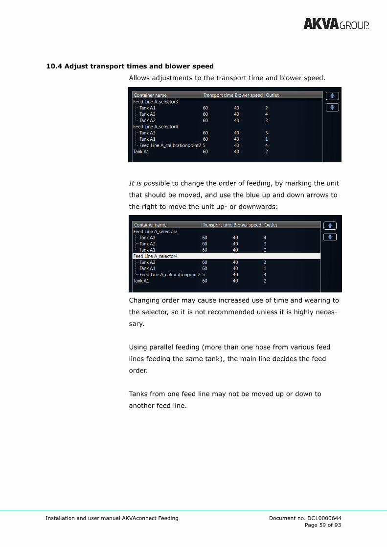
10.4 Adjust transport times and blower speed
Allows adjustments to the transport time and blower speed.
It is possible to change the order of feeding, by marking the unit
that should be moved, and use the blue up and down arrows to
the right to move the unit up- or downwards:
Changing order may cause increased use of time and wearing to
the selector, so it is not recommended unless it is highly neces-
sary.
Using parallel feeding (more than one hose from various feed
lines feeding the same tank), the main line decides the feed
order.
Tanks from one feed line may not be moved up or down to
another feed line.

Page 60 of 93
Installation and user manual AKVAconnect Feeding Document no. DC10000644
10.5 Machinery control (Machinery monitor)
This is an overview of all machinery in one feed line that enables
the user to monitor the equipment as the feeding proceeds.
Start machinery control - is only for authorized personnel.
It will stop all automatic feeding, and allow manual control of
machinery.
Starting machinery control equals stopping all automatic
feeding at own risk. For instance, if the blower is not started
before the doser is started, the doser and feeding hoses will be
clogged with feed.
Make sure to have full control over all processes and
components before starting manual feeding.

Page 61 of 93
Installation and user manual AKVAconnect Feeding Document no. DC10000644
10.6 Machinery parameters (Feedline parameters)
Controls parameters for the different machines attached to the
feed line. Normally used only by technicians.
10.6.1 Blower
Start delay: after the blower has started, the system will wait
this long before allowing other equipment to start
Stop delay: how long the blower blows after its program is
finished, in case there is a new request for feeding in the
immediate future
Wind down delay: time after the blower is stopped before it will
be started again.
Speed between feedings (%): blower speed between feedings.
10.6.2 Doser (pulse doser)
Speed when pulsing: dosing velocity when the doser pulses
Pulse on time (s): time the doser uses per pulse
Delivery rate (g/s): calibration value (if anything is changed, the
doser has to be calibrated, see chapter 10.3 for instructions)
Page 62 of 93
Installation and user manual AKVAconnect Feeding Document no. DC10000644
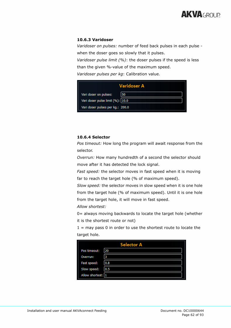
10.6.3 Varidoser
Varidoser on pulses: number of feed back pulses in each pulse -
when the doser goes so slowly that it pulses.
Varidoser pulse limit (%): the doser pulses if the speed is less
than the given %-value of the maximum speed.
Varidoser pulses per kg: Calibration value.
10.6.4 Selector
Pos timeout: How long the program will await response from the
selector.
Overrun: How many hundredth of a second the selector should
move after it has detected the lock signal.
Fast speed: the selector moves in fast speed when it is moving
far to reach the target hole (% of maximum speed).
Slow speed: the selector moves in slow speed when it is one hole
from the target hole (% of maximum speed). Until it is one hole
from the target hole, it will move in fast speed.
Allow shortest:
0= always moving backwards to locate the target hole (whether
it is the shortest route or not)
1 = may pass 0 in order to use the shortest route to locate the
target hole.
Page 63 of 93
Installation and user manual AKVAconnect Feeding Document no. DC10000644
10.7 Capacity utilization
Capacity utilization is limited by the feed system used.
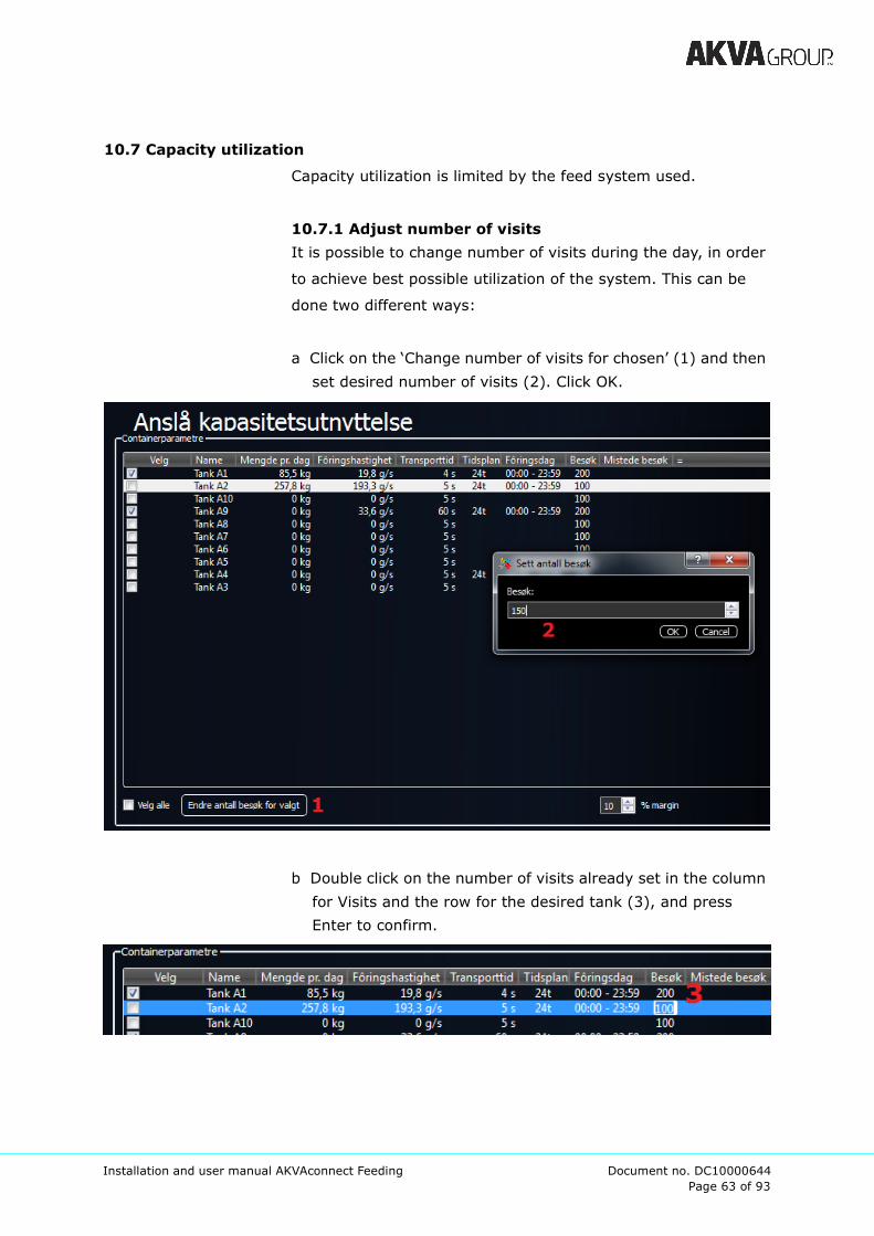
10.7.1 Adjust number of visits
It is possible to change number of visits during the day, in order
to achieve best possible utilization of the system. This can be
done two different ways:
a Click on the ‘Change number of visits for chosen’ (1) and then
set desired number of visits (2). Click OK.
b Double click on the number of visits already set in the column
for Visits and the row for the desired tank (3), and press
Enter to confirm.
Page 64 of 93
Installation and user manual AKVAconnect Feeding Document no. DC10000644
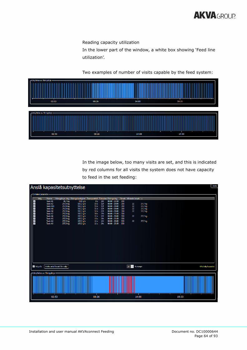
Reading capacity utilization
In the lower part of the window, a white box showing ‘Feed line
utilization’.
Two examples of number of visits capable by the feed system:
In the image below, too many visits are set, and this is indicated
by red columns for all visits the system does not have capacity
to feed in the set feeding:

Page 65 of 93
Installation and user manual AKVAconnect Feeding Document no. DC10000644
Visits that can not be executed, are indicated by red columns as
well as in the table under the column ‘Lost visits’. If these
appear, the number of visits must be reduced.
The best way to find the capacity for the specific site with the
specific feed plan, try different numbers of visits until all red
columns are gone, and ‘Lost visits’ are 0.
Make sure to have free capacity. This number should never be
0%, because this will lead to no safety margin for the feeding
capacity for instance when adjusting the appetite factor.
When using two different schedules, the overlapping periods can
cause red columns and lost visits if the number of visits are too
high. Other factors that can affect the capacity utilization
negatively, are low feeding rate and long transport time.
The number of visits should be adjusted regularly according to
the feeding schedule changing according to the fish growth.
When the feeding has problems with following the plan, and is
constantly delayed, this might be a good time for checking this.
Page 66 of 93
Installation and user manual AKVAconnect Feeding Document no. DC10000644
10.8 Hints
10.8.1 Apply symbols in their correct order
We recommend setting up all symbols in the process viewer
according to how the components are actually set up. Set the
first tank first, the second next and so on.
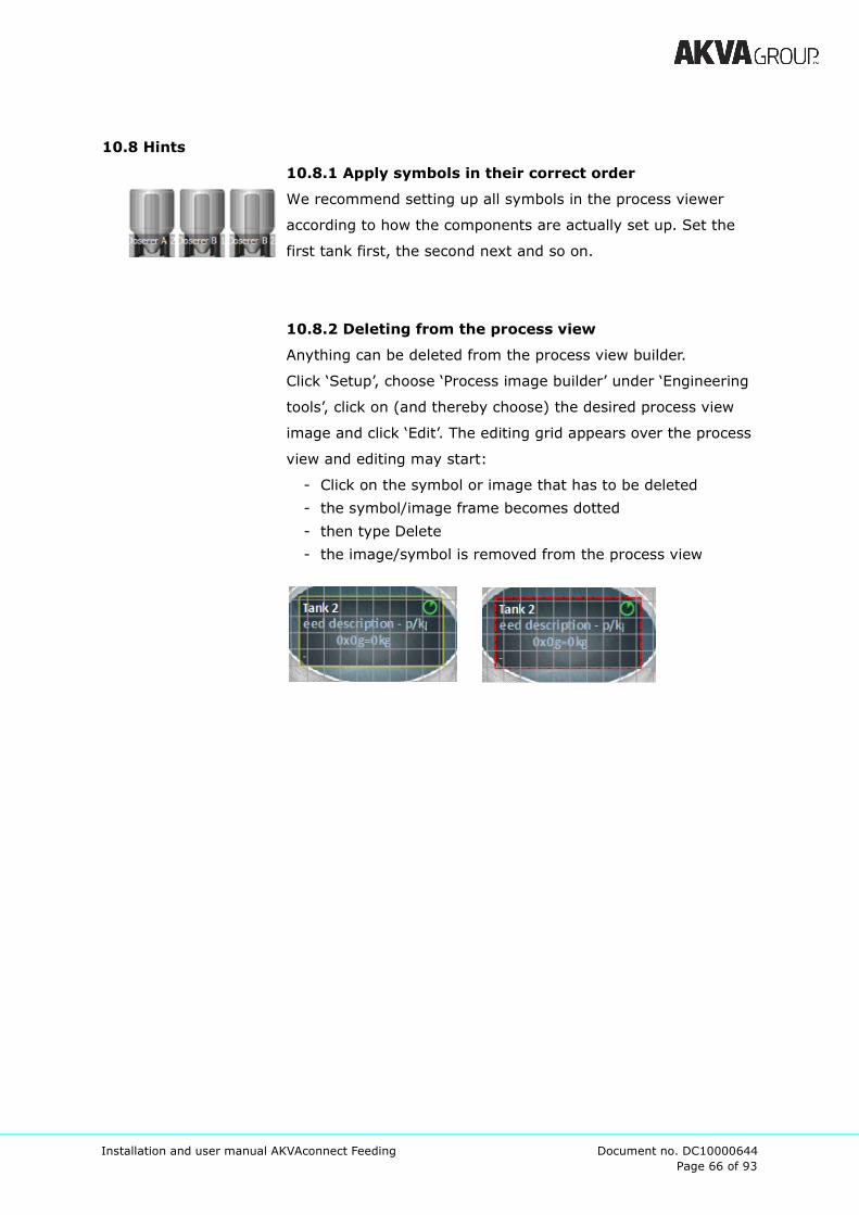
10.8.2 Deleting from the process view
Anything can be deleted from the process view builder.
Click ‘Setup’, choose ‘Process image builder’ under ‘Engineering
tools’, click on (and thereby choose) the desired process view
image and click ‘Edit’. The editing grid appears over the process
view and editing may start:
- Click on the symbol or image that has to be deleted
- the symbol/image frame becomes dotted
- then type Delete
- the image/symbol is removed from the process view
Page 67 of 93
Installation and user manual AKVAconnect Feeding Document no. DC10000644
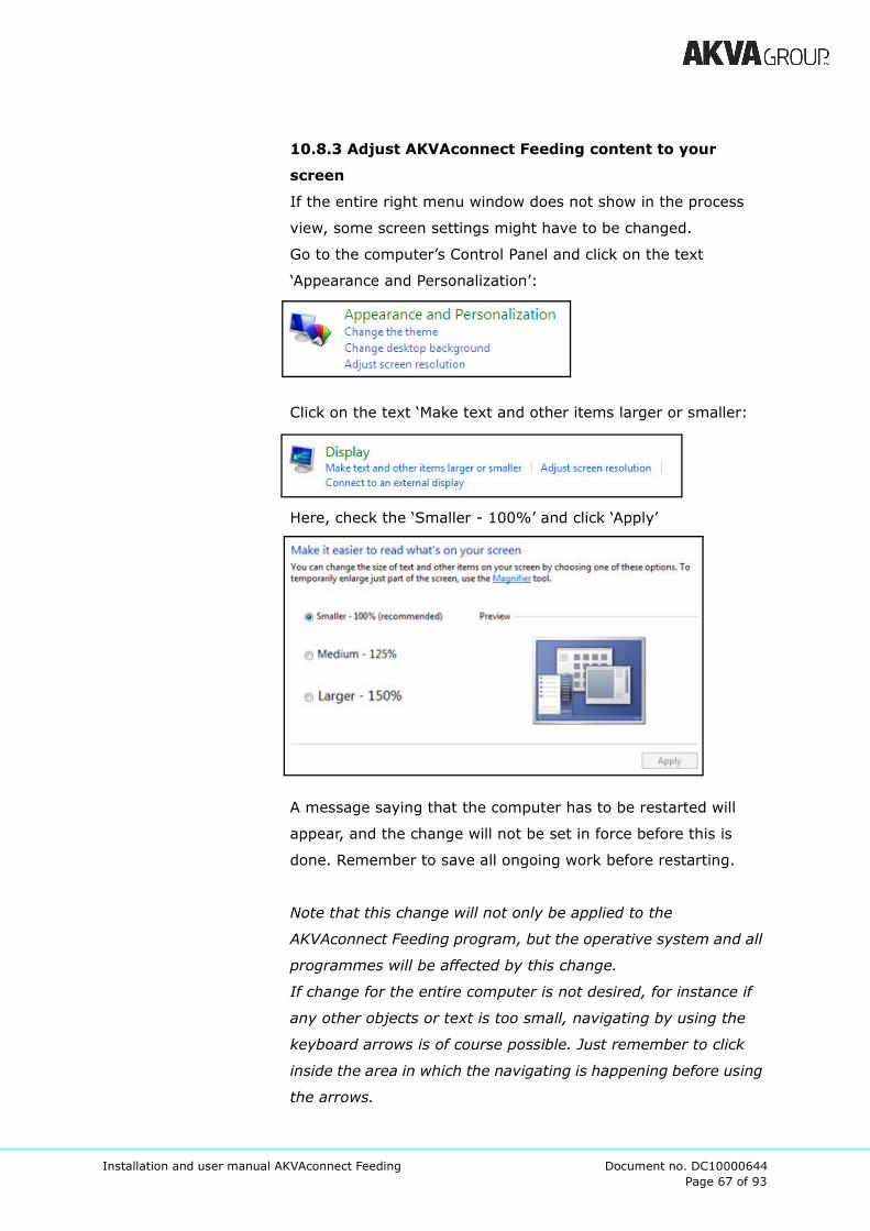
10.8.3 Adjust AKVAconnect Feeding content to your
screen
If the entire right menu window does not show in the process
view, some screen settings might have to be changed.
Go to the computer’s Control Panel and click on the text
‘Appearance and Personalization’:
Click on the text ‘Make text and other items larger or smaller:
Here, check the ‘Smaller - 100%’ and click ‘Apply’
A message saying that the computer has to be restarted will
appear, and the change will not be set in force before this is
done. Remember to save all ongoing work before restarting.
Note that this change will not only be applied to the
AKVAconnect Feeding program, but the operative system and all
programmes will be affected by this change.
If change for the entire computer is not desired, for instance if
any other objects or text is too small, navigating by using the
keyboard arrows is of course possible. Just remember to click
inside the area in which the navigating is happening before using
the arrows.

Page 68 of 93
Installation and user manual AKVAconnect Feeding Document no. DC10000644
11 Using AKVAconnect Feeding
11.1 The top menu
In the top right corner of the Process view, this menu is found:
This menu allows the user to navigate around the program,
making it possible to customize the specific site’s process.
1. The first symbol is a link to go to System settings, which
include these setting choices:
To return to the process view, click on the blue arrow to the right.

Page 69 of 93
Installation and user manual AKVAconnect Feeding Document no. DC10000644
2. The second symbol opens the Report viewer:
This area will contain all previous reports listed by category and
may be sorted by name or time.
It is possible to Save the report somewhere else, by using the
Save as button, it can be Deleted or Printed.
3. The grey fish is a link to the Feeding setup. See chapter 9.3
for more information about this setup section and its sub-
sections.
Page 70 of 93
Installation and user manual AKVAconnect Feeding Document no. DC10000644
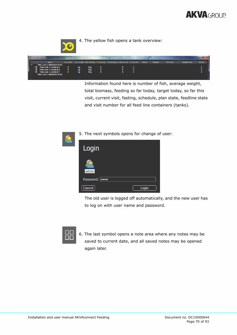
4. The yellow fish opens a tank overview:
Information found here is number of fish, average weight,
total biomass, feeding so far today, target today, so far this
visit, current visit, fasting, schedule, plan state, feedline state
and visit number for all feed line containers (tanks).
5. The next symbols opens for change of user:
The old user is logged off automatically, and the new user has
to log on with user name and password.
6. The last symbol opens a note area where any notes may be
saved to current date, and all saved notes may be opened
again later.
Page 71 of 93
Installation and user manual AKVAconnect Feeding Document no. DC10000644
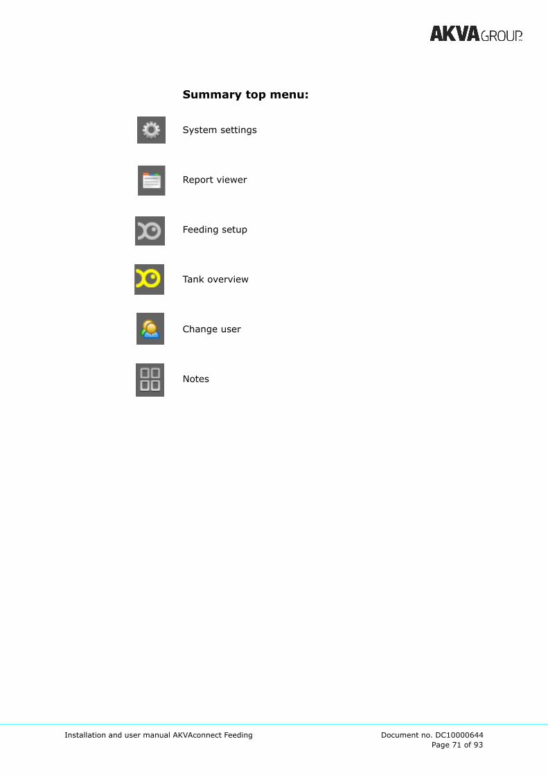
Summary top menu:
System settings
Report viewer
Feeding setup
Tank overview
Change user
Notes
Page 72 of 93
Installation and user manual AKVAconnect Feeding Document no. DC10000644
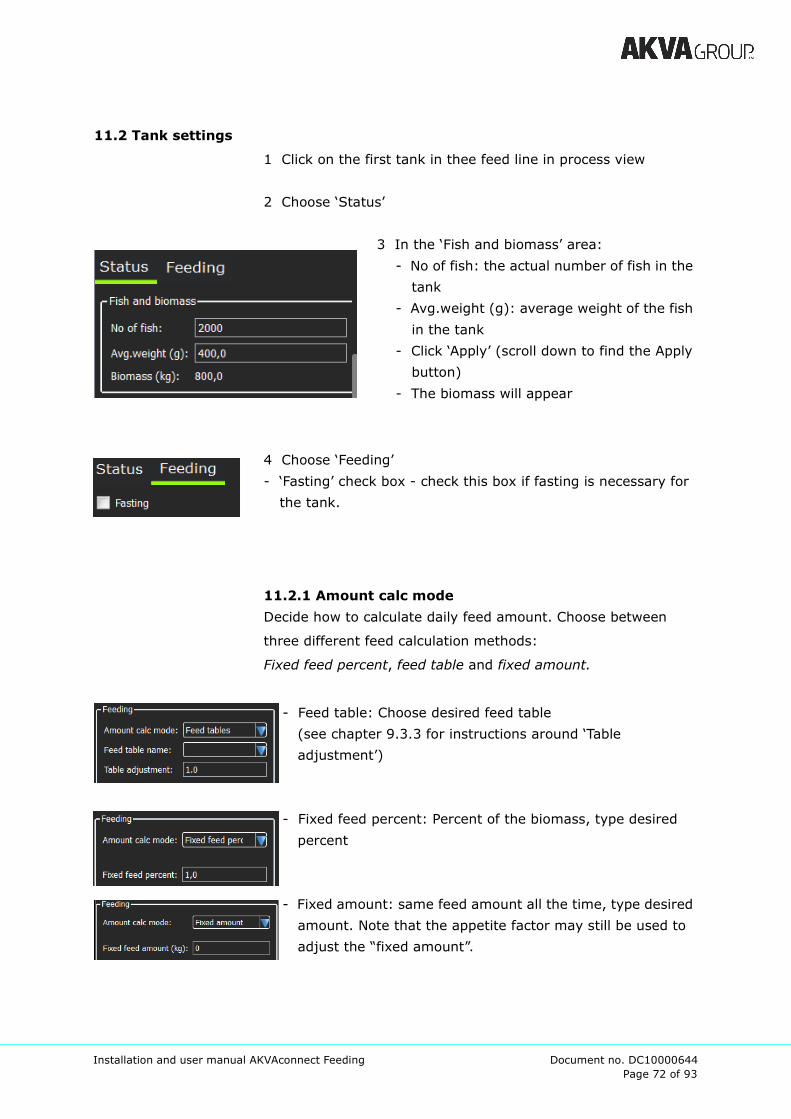
11.2 Tank settings
1 Click on the first tank in thee feed line in process view
2 Choose ‘Status’
3 In the ‘Fish and biomass’ area:
- No of fish: the actual number of fish in the
tank
- Avg.weight (g): average weight of the fish
in the tank
- Click ‘Apply’ (scroll down to find the Apply
button)
- The biomass will appear
4 Choose ‘Feeding’
- ‘Fasting’ check box - check this box if fasting is necessary for
the tank.
11.2.1 Amount calc mode
Decide how to calculate daily feed amount. Choose between
three different feed calculation methods:
Fixed feed percent, feed table and fixed amount.
- Feed table: Choose desired feed table
(see chapter 9.3.3 for instructions around ‘Table
adjustment’)
- Fixed feed percent: Percent of the biomass, type desired
percent
- Fixed amount: same feed amount all the time, type desired
amount. Note that the appetite factor may still be used to
adjust the “fixed amount”.
Page 73 of 93
Installation and user manual AKVAconnect Feeding Document no. DC10000644
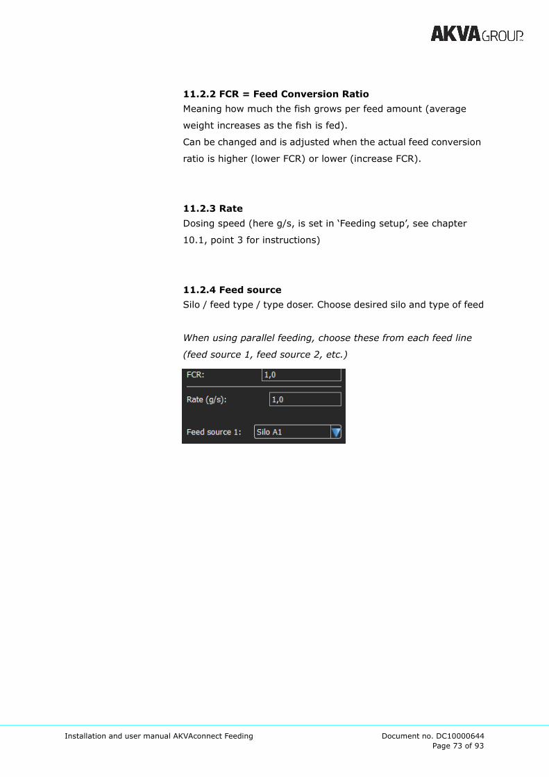
11.2.2 FCR = Feed Conversion Ratio
Meaning how much the fish grows per feed amount (average
weight increases as the fish is fed).
Can be changed and is adjusted when the actual feed conversion
ratio is higher (lower FCR) or lower (increase FCR).
11.2.3 Rate
Dosing speed (here g/s, is set in ‘Feeding setup’, see chapter
10.1, point 3 for instructions)
11.2.4 Feed source
Silo / feed type / type doser. Choose desired silo and type of feed
When using parallel feeding, choose these from each feed line
(feed source 1, feed source 2, etc.)
Page 74 of 93
Installation and user manual AKVAconnect Feeding Document no. DC10000644
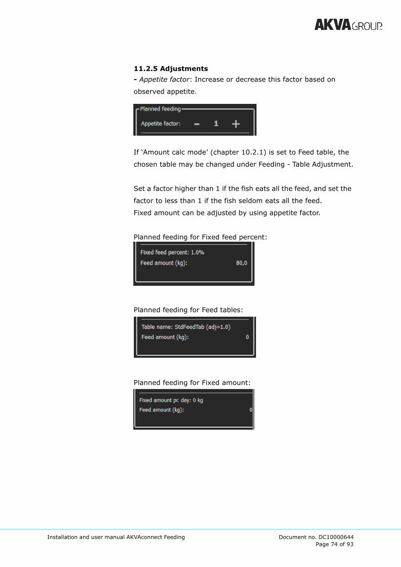
11.2.5 Adjustments
- Appetite factor: Increase or decrease this factor based on
observed appetite.
If ‘Amount calc mode’ (chapter 10.2.1) is set to Feed table, the
chosen table may be changed under Feeding - Table Adjustment.
Set a factor higher than 1 if the fish eats all the feed, and set the
factor to less than 1 if the fish seldom eats all the feed.
Fixed amount can be adjusted by using appetite factor.
Planned feeding for Fixed feed percent:
Planned feeding for Feed tables:
Planned feeding for Fixed amount:

Page 75 of 93
Installation and user manual AKVAconnect Feeding Document no. DC10000644
11.2.6 Feeding status
So far today - amount fed today, after midnight
Feed amount last X hours: amount fed the last X hours
(number of hours are adjusted in the slider below from 1 to 24h)
11.2.7 Feed line control symbols
In the upper right corner of the tank symbols in process view, a
symbol is shown to indicate where in the feeding process the
specific tank is at the moment:
Page 76 of 93
Installation and user manual AKVAconnect Feeding Document no. DC10000644
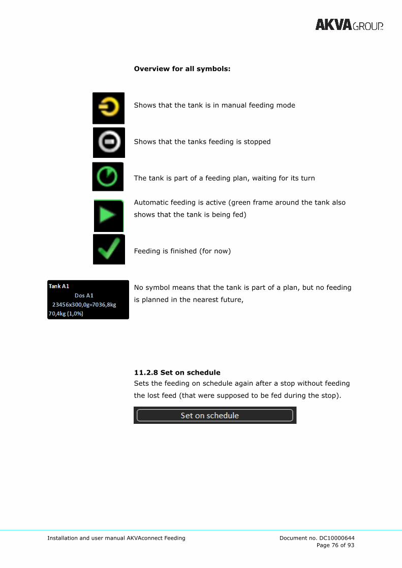
Overview for all symbols:
Shows that the tank is in manual feeding mode
Shows that the tanks feeding is stopped
The tank is part of a feeding plan, waiting for its turn
Automatic feeding is active (green frame around the tank also
shows that the tank is being fed)
Feeding is finished (for now)
No symbol means that the tank is part of a plan, but no feeding
is planned in the nearest future,
11.2.8 Set on schedule
Sets the feeding on schedule again after a stop without feeding
the lost feed (that were supposed to be fed during the stop).
Page 77 of 93
Installation and user manual AKVAconnect Feeding Document no. DC10000644
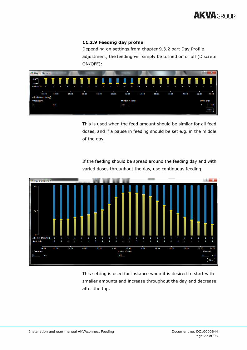
11.2.9 Feeding day profile
Depending on settings from chapter 9.3.2 part Day Profile
adjustment, the feeding will simply be turned on or off (Discrete
ON/OFF):
This is used when the feed amount should be similar for all feed
doses, and if a pause in feeding should be set e.g. in the middle
of the day.
If the feeding should be spread around the feeding day and with
varied doses throughout the day, use continuous feeding:
This setting is used for instance when it is desired to start with
smaller amounts and increase throughout the day and decrease
after the top.

Page 78 of 93
Installation and user manual AKVAconnect Feeding Document no. DC10000644
11.3 Silo
Click on desired silo, choose ‘Refill silo’ in the right side menu.
Click on desired silo i Process view
Choose ‘Silo’
Choose ‘Refill silo...’
Opens a new window:
1. Type in correct silo capacity (at the bottom)
2. Type correct amount of feed that is filled into the silo
3. Give the refill a description (for instance supplier and feed
size. If this feed type has been used before, this can be
chosen from the drop down menu.)
4. Save
5. The refill will appear under History.
(It is possible to delete the refill by marking the line (it will
turned orange) and click on the X on the left side. It is
important to save, and to check that the silo amount is
correct before proceeding.)
6. Close the window.
Page 79 of 93
Installation and user manual AKVAconnect Feeding Document no. DC10000644
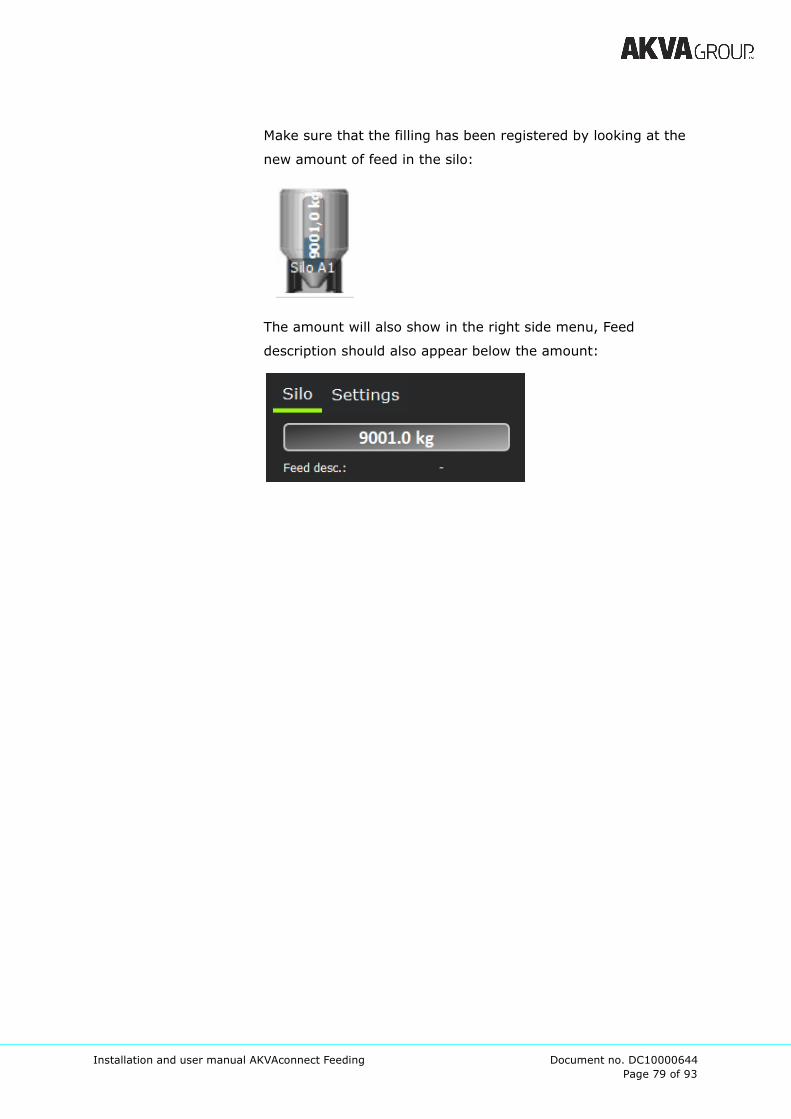
Make sure that the filling has been registered by looking at the
new amount of feed in the silo:
The amount will also show in the right side menu, Feed
description should also appear below the amount:
Page 80 of 93
Installation and user manual AKVAconnect Feeding Document no. DC10000644
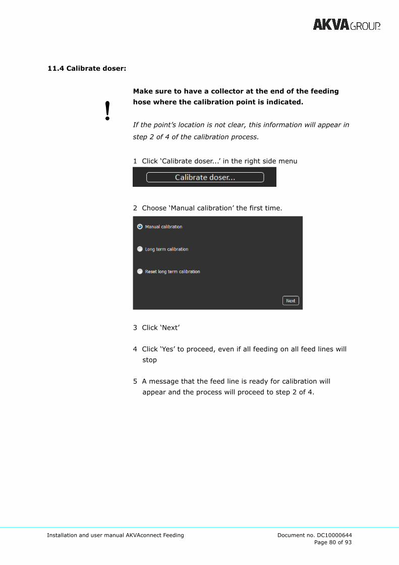
11.4 Calibrate doser:
Make sure to have a collector at the end of the feeding
hose where the calibration point is indicated.
If the point’s location is not clear, this information will appear in
step 2 of 4 of the calibration process.
1 Click ‘Calibrate doser...’ in the right side menu
2 Choose ‘Manual calibration’ the first time.
3 Click ‘Next’
4 Click ‘Yes’ to proceed, even if all feeding on all feed lines will
stop
5 A message that the feed line is ready for calibration will
appear and the process will proceed to step 2 of 4.

Page 81 of 93
Installation and user manual AKVAconnect Feeding Document no. DC10000644
6 Rate: the system will suggest a feeding speed based on all
tanks connected to the current silo. The rate may be changed
if desired.
7 ‘Desired feed amount’: Type in desired feed amount in grams
(for instance 5000g = 5kg or 1.000.000g = 1000kg)
8 Click ‘Start calibrating’
9 The calibrating process will proceed until ‘Output amount so
far’ reaches ‘Desired feed amount’ and is indicated by orange
letters spelling out “CALIBRATING”:
10 When the calibration process is finished, the ‘Calibrating
indication’ will be replaced by “DONE”:
11 Click ‘Next’
Page 82 of 93
Installation and user manual AKVAconnect Feeding Document no. DC10000644
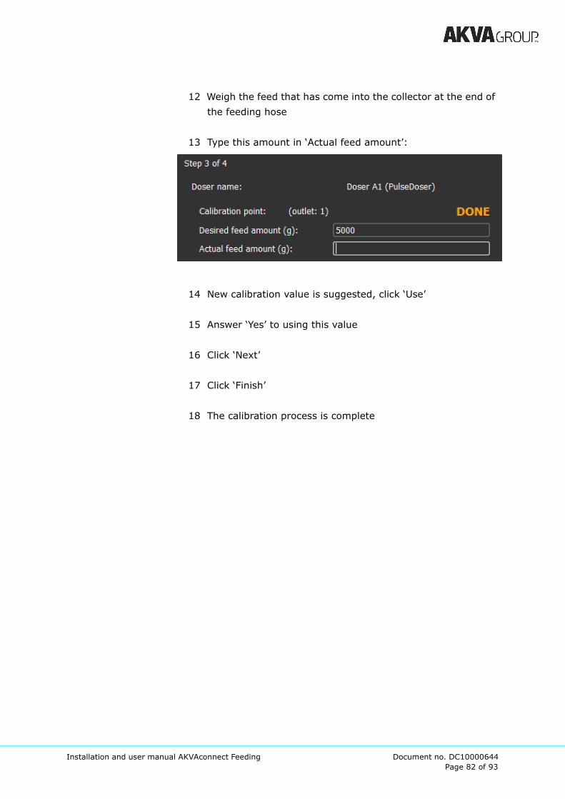
12 Weigh the feed that has come into the collector at the end of
the feeding hose
13 Type this amount in ‘Actual feed amount’:
14 New calibration value is suggested, click ‘Use’
15 Answer ‘Yes’ to using this value
16 Click ‘Next’
17 Click ‘Finish’
18 The calibration process is complete
Page 83 of 93
Installation and user manual AKVAconnect Feeding Document no. DC10000644
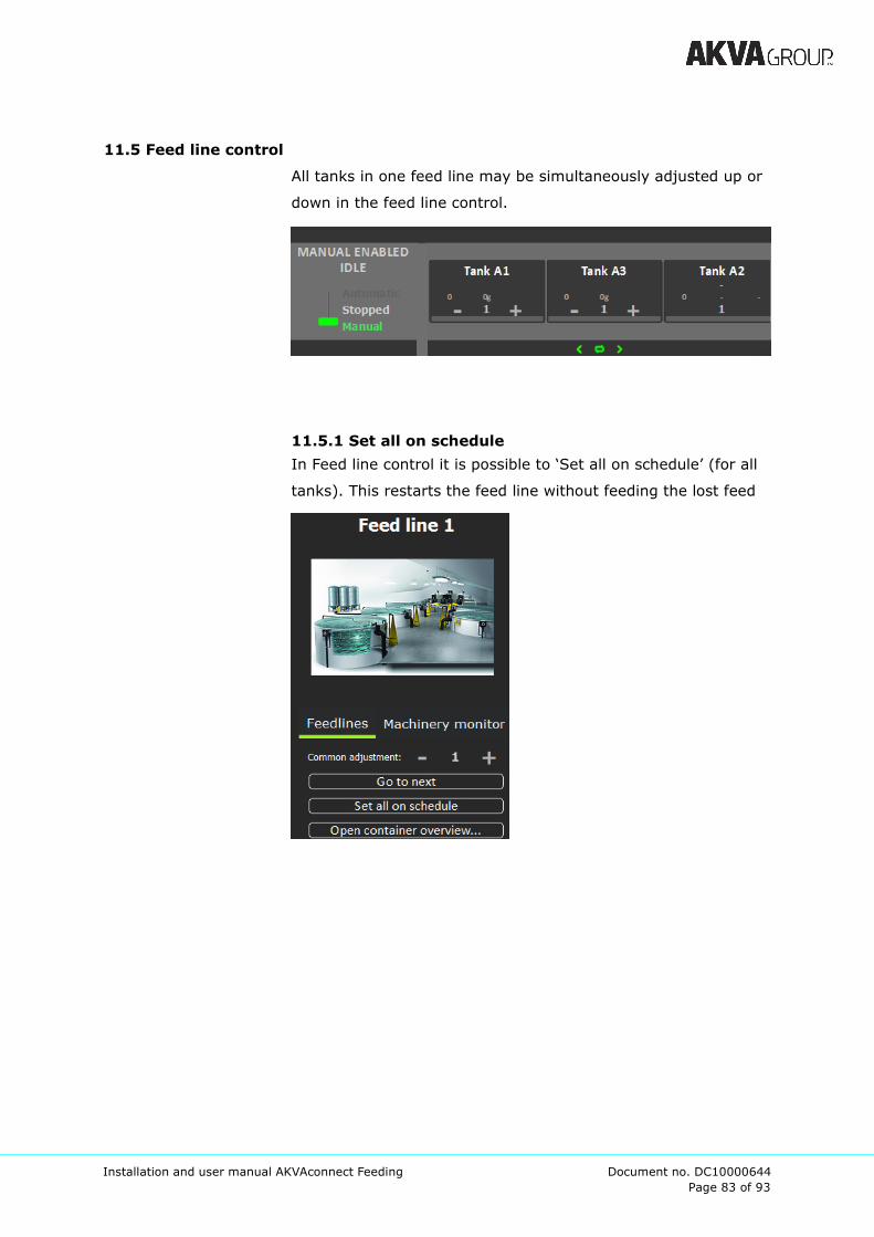
11.5 Feed line control
All tanks in one feed line may be simultaneously adjusted up or
down in the feed line control.
11.5.1 Set all on schedule
In Feed line control it is possible to ‘Set all on schedule’ (for all
tanks). This restarts the feed line without feeding the lost feed

Page 84 of 93
Installation and user manual AKVAconnect Feeding Document no. DC10000644
11.5.2 Reading the feed line control
The feed line control area will also indicate where the different
tanks are in the feeding process.
Automatic feeding is activated, feeding will start at 16:04:47 for
Waiting for blower to feed Tank A2:
Selector is running and is about to feed Tank A1:
Dosing out feed for Tank A2:
An after-feeding blowing is happening to empty feed from the
hose:

Page 85 of 93
Installation and user manual AKVAconnect Feeding Document no. DC10000644
11.6 Register mortality...
When registering morts, use either number of fish, or total
weight to the morts.
Number of fish: type number of fish and average weight.
Total weight: type total weight and average weight.
Remember to click Save before closing.

Page 86 of 93
Installation and user manual AKVAconnect Feeding Document no. DC10000644
12 Troubleshooting
If this message appears on the screen, the licence for the PC has
expired. Contact AKVA to renew it.

Page 87 of 93
Installation and user manual AKVAconnect Feeding Document no. DC10000644
Appendix A - Index list
A
access 19, 21
access control 37
accumulated feed amount 45
actions 21
activate IO 26
actual feed amount 66
add clock 42
add Users 19, 22
adjust transport times and blower speed 47
air/pellet flow 30
allow shortest 50
amount calc mode 46, 56, 58
amount of feed in the silo 63
appetite factor 56, 58
application builder 23, 26
apply 44, 51, 56
apply symbols 51
automatic feeding 48, 60
average weight 45, 55, 56, 57, 69
B
biomass 45, 55, 56
blower 24, 28, 29, 33, 47-49, 68
blue arrow 21, 35, 53
browse 41, 43
C
calibrate doser 64
calibrating indication 65
calibration point 30, 32, 33, 64
calibration value 49, 50, 66
category 54
change user 55
click-and-drag 33, 40
client PC 11
close 16, 18, 21, 27, 38, 62
collector 64, 66
component 24, 25, 28-30, 36, 39, 40, 42,
48, 51
continuous 45, 61
continuous feeding 61
current visit 55
customize system 45
D
daily feed 44, 56
day profile 45
delete 51, 54, 62
delivery rate 49
description 23, 37, 43, 62, 63
desired feed amount 65
device ID 43
discrete ON/OFF 45, 60
display name 29, 29
display units 45
dose amount 45
doser 24, 28, 29, 33, 48, 49, 50, 57, 64
doserILC 24, 26
dotted frame 31, 35
download 11, 16
drop down menu 20, 62
E
edit 37, 38, 40, 42, 46, 51
edit background 41
edit Processview 38, 46
electrician 28, 29
F
farmer 19-22
fast speed 50
fasting 55, 56
FCR 57
feed amount 32, 45, 46, 56, 60, 65, 66
Page 88 of 93
Installation and user manual AKVAconnect Feeding Document no. DC10000644
feed amount last X hours 59
feed container 42
feed Conversion Ratio 57
feed description 63
feed line 25-30, 32-35, 37, 42, 47-49,
55-57, 59, 64, 67, 68
feed line area 29, 35
feed line control 25, 28, 33, 35, 42, 67, 68
feed line control symbols 59
feed rate unit 45
feed source 57
feed table 46, 56, 58
feed type 62
feeding 23, 25, 29, 30, 32-34, 39, 42,
51-61, 64-68
feeding client 19
feeding is finished 60
feeding is stopped 59
feeding schedule 44
feeding settings 44
feeding setup 54
feeding so far today 55
feedline parameters 49
feedline state 55
fish and biomass 56
fixed amount 56, 58
fixed feed percent 56, 58
G
generate Application 27
grams/sec 45
green frame 60
grid 38
GUI- components 39
GUI-components 40
H
hints 36
history 62
I
I/O 23
ILC 23
increasing the feed 46
individual settings 45
installation 11
IP address 23
K
kg/minute 45
kg/ton/minute 45
L
language 11
lowering the feed amount 46
M
machinery control 48
machinery monitor 48
machinery parameters 49
main feed line 33, 34
main menu 20-23, 37
MainILC 24
manual calibration 64
manual feeding 48
manual feeding mode 59
modify 29
monitor the equipment 48
more feed lines 35
N
name 23-25, 28, 29, 37, 42-44, 46, 54
new application 23
Next 23, 64-66
no of fish 56, 59
no symbol 55, 60
notes 55

Page 89 of 93
Installation and user manual AKVAconnect Feeding Document no. DC10000644
O
object 28, 29, 31, 38-40, 42, 52
offsets 45
overrun 50
overview 18, 39, 41, 48, 55, 59
P
parallel feeding 33, 47, 57
part of a feeding plan 59
plan state 55
Planned feeding 58
PLC 23, 40
PLC-objects 40
pos timeout 50
process 27, 31, 32, 48, 53, 59
process image builder 38, 51
process image elements 40
process view 18, 37, 38, 41-43, 46, 51-53,
56, 59, 62
properties 37, 42
pulse doser 49
pulse on time 49
R
rate 33, 49, 57, 65
refill silo 62
register mortality 69
remove 31, 35, 51
remove 51
report viewer 54
resolution 37
return to the process view 53
role 19, 20
S
save 27
schedule 27, 52, 55, 62, 69
selector 24, 29-34, 47, 50, 68
selectorILC 24, 26
sensor Drive 39
sequential feeding 32
server 11, 13, 16, 17, 37
server PC 11
set all on schedule 67
set on schedule 60
set up 23, 25-27, 33-37, 42, 51
set up silo 42
settings 20, 22, 37, 38, 40, 41, 44, 45, 52,
53, 60
show device area by default 40
show general settings 38, 40
show grid 26
silo 29, 42, 57, 62, 63, 65
silo capacity 62
simultaneously adjusted 67
site manager 19-22
slow speed 50
so far this visit 55
so far today 59
speed when pulsing 49
standard feed table 46
start calibrating 65
start delay 49
status 56
stop delay 49
symbol size 36
system settings 19, 53
systematic names 24, 29
T
tank 28-34, 36, 45-47, 51, 55, 56, 59, 60,
65, 67, 57
tank overview 55
tank settings 56
target today 55
technician 19-22, 28, 49
temperature sensor 30
template 37
top menu 53
total biomass 55
total weight 69

Page 90 of 93
Installation and user manual AKVAconnect Feeding Document no. DC10000644
V
validate 26
varidoser on pulses 50
varidoser pulse limit 50
varidoser pulses per kg 50
varidosers 28, 29, 50
visit number 55
W
white box 25, 28, 33, 35
wind down delay 49
Page 91 of 93
Installation and user manual AKVAconnect Feeding Document no. DC10000644
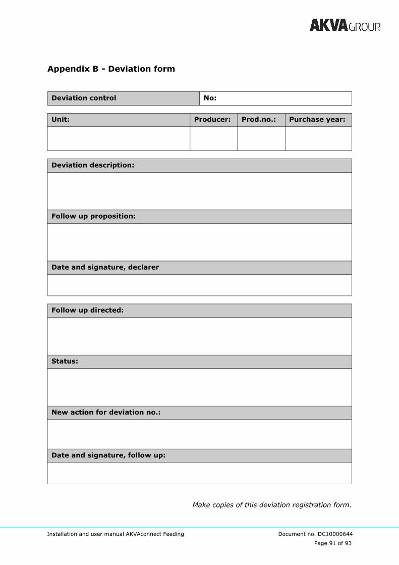
Appendix B - Deviation form
Make copies of this deviation registration form.
Deviation control No:
Unit: Producer: Prod.no.: Purchase year:
Deviation description:
Follow up proposition:
Date and signature, declarer
Follow up directed:
Status:
New action for deviation no.:
Date and signature, follow up:
of 93
Page 92 of 93
Installation and user manual AKVAconnect Feeding Document no. DC10000644
Appendix C - Notes
of 93
Page 93 of 93
Installation and user manual AKVAconnect Feeding Document no. DC10000644