installation and user manual -...
TRANSCRIPT
Honeywell
Installation and User Manual
Modbus protocolfor Variable Frequency Drives
62-0351-01
Honeywell • 1
INDEXDocument:DPD00372A
Version release date: 29/12/10
1. Safety ............................................................................................................................. 21.1 Danger ................................................................................................................... 21.2 Warnings................................................................................................................ 31.3 Grounding and ground fault protection .................................................................. 3
2. Modbus - general info................................................................................................... 53. Modbus technical data ................................................................................................. 7
3.1 Modbus RTU protocol............................................................................................ 73.2 Modbus TCP protocol ............................................................................................ 7
4. Modbus installation ...................................................................................................... 84.1 Prepare for use through ethernet........................................................................... 94.2 Prepare for use through RTU .............................................................................. 11
5. Programming............................................................................................................... 145.1 Modbus RTU parameters and monitoring values (M5.7.3).................................. 145.2 Modbus TCP parameters and monitoring values ................................................ 165.2.1 Ethernet common settings (M5.8.1)..................................................................... 165.2.2 Modbus TCP settings (M5.8.2) ............................................................................ 165.3 Modbus RTU parameter descriptions .................................................................. 175.3.1 Modbus RTU Parameters .................................................................................... 175.3.2 Modbus RTU monitoring values .......................................................................... 175.4 Modbus TCP parameter descriptions .................................................................. 195.4.1 Ethernet common settings ................................................................................... 195.4.2 Modbus TCP settings .......................................................................................... 20
5.4.2.1 Common settings ..................................................................................................... 205.4.3 Modbus TCP monitoring values........................................................................... 20
5.4.3.1 Connection 1 ............................................................................................................ 205.4.3.2 Connection 2 ............................................................................................................ 21
6. Communications......................................................................................................... 226.1 Data addresses in Modbus messages................................................................. 226.2 Modbus memory map.......................................................................................... 226.3 Modbus data mapping ......................................................................................... 236.3.1 Coil registers........................................................................................................ 236.3.2 Input discrete registers ........................................................................................ 236.3.3 Holding and input registers .................................................................................. 23
6.3.3.1 Drive Application ID’s ............................................................................................... 246.3.3.2 FB Process data IN .................................................................................................. 246.3.3.3 FB Process data OUT .............................................................................................. 266.3.3.4 ID map...................................................................................................................... 276.3.3.5 Operation day counter.............................................................................................. 286.3.3.6 Resettable operation day counter ............................................................................ 296.3.3.7 Energy counter ......................................................................................................... 296.3.3.8 Resettable energy counter ....................................................................................... 296.3.3.9 Fault history.............................................................................................................. 30
6.4 Example messages ............................................................................................. 317. Fault tracing ................................................................................................................ 34
7.1 Typical fault conditions ........................................................................................ 347.2 RS-485 bus biasing ............................................................................................. 347.3 Other fault conditions........................................................................................... 35
8. Quick setup ................................................................................................................. 379. Annex ........................................................................................................................... 38
Honeywell • 2 Safety
1. Safety
This manual contains clearly marked cautions and warnings which are intended for your per-sonal safety and to avoid any unintentional damage to the product or connected appliances.
Please read the information included in cautions and warnings carefully.
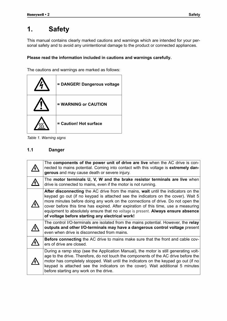
The cautions and warnings are marked as follows:
Table 1. Warning signs
1.1 Danger
= DANGER! Dangerous voltage
= WARNING or CAUTION
= Caution! Hot surface
The components of the power unit of drive are live when the AC drive is con-nected to mains potential. Coming into contact with this voltage is extremely dan-gerous and may cause death or severe injury.
The motor terminals U, V, W and the brake resistor terminals are live whendrive is connected to mains, even if the motor is not running.
After disconnecting the AC drive from the mains, wait until the indicators on thekeypad go out (if no keypad is attached see the indicators on the cover). Wait 5more minutes before doing any work on the connections of drive. Do not open thecover before this time has expired. After expiration of this time, use a measuringequipment to absolutely ensure that no voltage is present. Always ensure absenceof voltage before starting any electrical work!
The control I/O-terminals are isolated from the mains potential. However, the relayoutputs and other I/O-terminals may have a dangerous control voltage presenteven when drive is disconnected from mains.
Before connecting the AC drive to mains make sure that the front and cable cov-ers of drive are closed.
During a ramp stop (see the Application Manual), the motor is still generating volt-age to the drive. Therefore, do not touch the components of the AC drive before themotor has completely stopped. Wait until the indicators on the keypad go out (if nokeypad is attached see the indicators on the cover). Wait additional 5 minutesbefore starting any work on the drive.
Safety Honeywell • 3
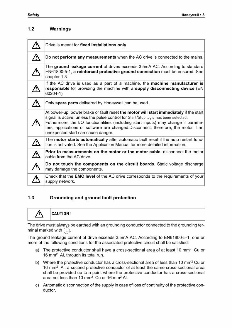
1.2 Warnings
1.3 Grounding and ground fault protection
The drive must always be earthed with an grounding conductor connected to the grounding ter-minal marked with .
The ground leakage current of drive exceeds 3.5mA AC. According to EN61800-5-1, one ormore of the following conditions for the associated protective circuit shall be satisfied:
a) The protective conductor shall have a cross-sectional area of at least 10 mm2 Cu or16 mm2 Al, through its total run.
b) Where the protective conductor has a cross-sectional area of less than 10 mm2 Cu or16 mm2 Al, a second protective conductor of at least the same cross-sectional areashall be provided up to a point where the protective conductor has a cross-sectionalarea not less than 10 mm2 Cu or 16 mm2 Al.
c) Automatic disconnection of the supply in case of loss of continuity of the protective con-ductor.
Drive is meant for fixed installations only.
Do not perform any measurements when the AC drive is connected to the mains.
The ground leakage current of drives exceeds 3.5mA AC. According to standardEN61800-5-1, a reinforced protective ground connection must be ensured. Seechapter 1.3.
If the AC drive is used as a part of a machine, the machine manufacturer isresponsible for providing the machine with a supply disconnecting device (EN60204-1).
Only spare parts delivered by Honeywell can be used.
At power-up, power brake or fault reset the motor will start immediately if the startsignal is active, unless the pulse control for Start/Stop logic has been selected.Futhermore, the I/O functionalities (including start inputs) may change if parame-ters, applications or software are changed.Disconnect, therefore, the motor if anunexpected start can cause danger.
The motor starts automatically after automatic fault reset if the auto restart func-tion is activated. See the Application Manual for more detailed information.
Prior to measurements on the motor or the motor cable, disconnect the motorcable from the AC drive.
Do not touch the components on the circuit boards. Static voltage dischargemay damage the components.
Check that the EMC level of the AC drive corresponds to the requirements of yoursupply network.
CAUTION!

Honeywell • 4 Safety
The cross-sectional area of every protective grounding conductor which does not form part ofthe supply cable or cable enclosure shall, in any case, be not less than:
- 2.5mm2 if mechanical protection is provided or- 4mm2 if mechanical protection is not provided.
The ground fault protection inside the AC drive protects only the drive itself against groundfaults in the motor or the motor cable. It is not intended for personal safety.
Due to the high capacitive currents present in the AC drive, fault current protective switchesmay not function properly.
Do not perform any voltage withstand tests on any part of drive. There is a cer-tain procedure according to which the tests shall be performed. Ignoring this pro-cedure may result in damaged product.
Modbus - general info Honeywell • 5
2. Modbus - general info
Modbus is a communication protocol developed by Modicon systems. In simple terms, it is away of sending information between electronic devices. The device requesting the informationis called the Modbus Master (or the Client in Modbus TCP) and the devices supplying informa-tion are Modbus Slaves (in Modbus TCP servers). In a standard Modbus network, there is oneMaster and up to 247 Slaves, each with a unique Slave Address from 1 to 247. The Master canalso write information to the Slaves. Modbus is typically used to transmit signals from instru-mentation and control devices back to a main controller or data gathering system.
The Modbus communication interface is built around messages. The format of these Modbusmessages is independent of the type of physical interface used. The same protocol can beused regardless of the connection type. Because of this, Modbus gives the possibility to easilyupgrade the hardware structure of an industrial network, without the need for large changes inthe software. A device can also communicate with several Modbus nodes at once, even if theyare connected with different interface types, without the need to use a different protocol for ev-ery connection.
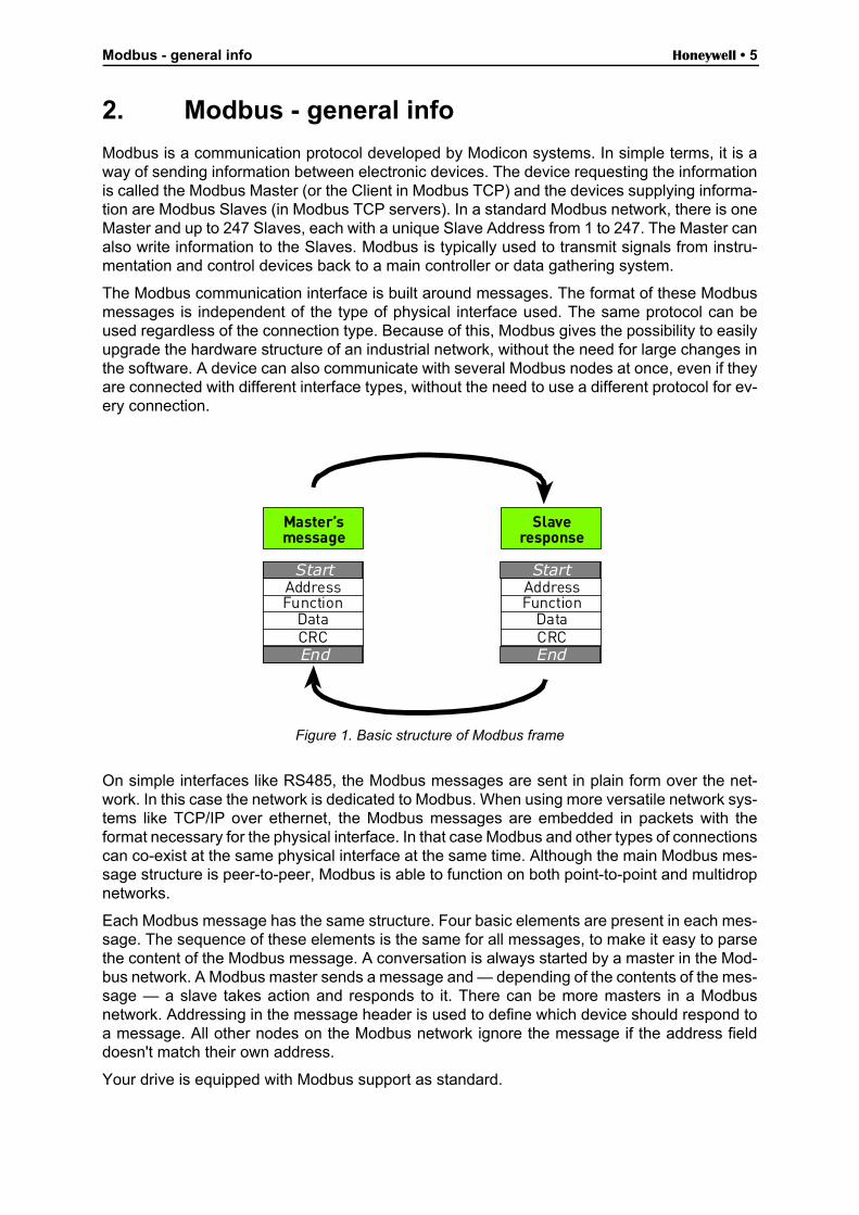
Figure 1. Basic structure of Modbus frame
On simple interfaces like RS485, the Modbus messages are sent in plain form over the net-work. In this case the network is dedicated to Modbus. When using more versatile network sys-tems like TCP/IP over ethernet, the Modbus messages are embedded in packets with theformat necessary for the physical interface. In that case Modbus and other types of connectionscan co-exist at the same physical interface at the same time. Although the main Modbus mes-sage structure is peer-to-peer, Modbus is able to function on both point-to-point and multidropnetworks.
Each Modbus message has the same structure. Four basic elements are present in each mes-sage. The sequence of these elements is the same for all messages, to make it easy to parsethe content of the Modbus message. A conversation is always started by a master in the Mod-bus network. A Modbus master sends a message and — depending of the contents of the mes-sage — a slave takes action and responds to it. There can be more masters in a Modbusnetwork. Addressing in the message header is used to define which device should respond toa message. All other nodes on the Modbus network ignore the message if the address fielddoesn't match their own address.
Your drive is equipped with Modbus support as standard.
Master’smessage
Slaveresponse
AddressFunction
DataCRC
AddressFunction
DataCRC
Start
End
Start
End
Honeywell • 6 Modbus - general info
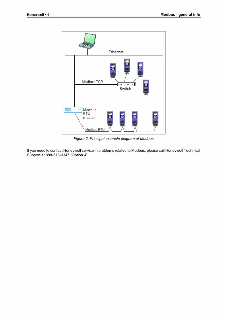
Figure 2. Principal example diagram of Modbus
If you need to contact Honeywell service in problems related to Modbus, please call Honeywell TechnicalSupport at 888-516-9347 “Option 4”.
Ethernet
ModbusRTUmaster
Switch
Modbus TCP
Modbus RTU
Modbus technical data Honeywell • 7
3. Modbus technical data
3.1 Modbus RTU protocol
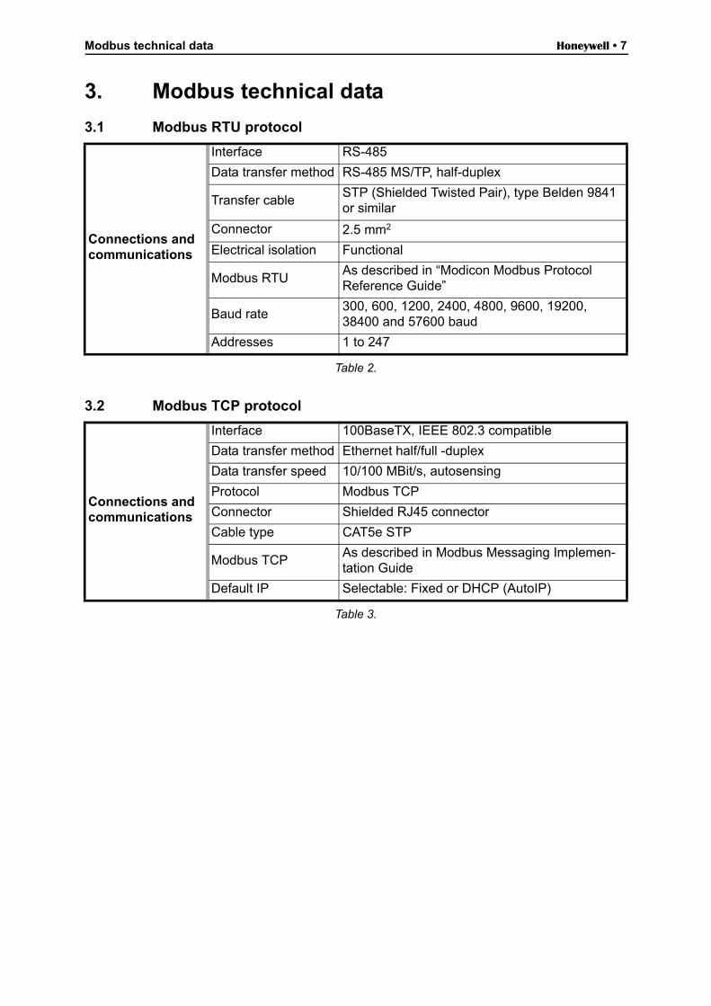
Table 2.
3.2 Modbus TCP protocol
Table 3.
Connections and communications
Interface RS-485
Data transfer method RS-485 MS/TP, half-duplex
Transfer cableSTP (Shielded Twisted Pair), type Belden 9841 or similar
Connector 2.5 mm2
Electrical isolation Functional
Modbus RTUAs described in “Modicon Modbus Protocol Reference Guide”
Baud rate300, 600, 1200, 2400, 4800, 9600, 19200, 38400 and 57600 baud
Addresses 1 to 247
Connections and communications
Interface 100BaseTX, IEEE 802.3 compatible
Data transfer method Ethernet half/full -duplex
Data transfer speed 10/100 MBit/s, autosensing
Protocol Modbus TCP
Connector Shielded RJ45 connector
Cable type CAT5e STP
Modbus TCPAs described in Modbus Messaging Implemen-tation Guide
Default IP Selectable: Fixed or DHCP (AutoIP)
Honeywell • 8 Modbus installation
4. Modbus installation
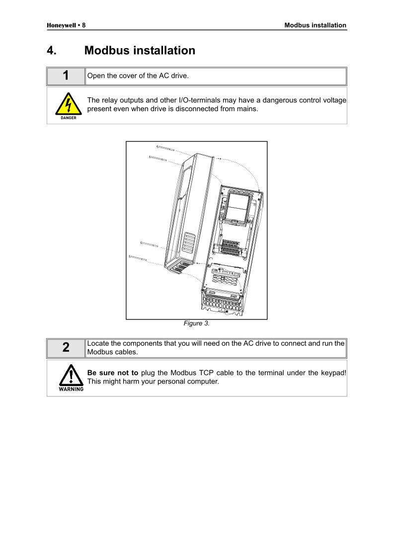
Figure 3.
1 Open the cover of the AC drive.
The relay outputs and other I/O-terminals may have a dangerous control voltagepresent even when drive is disconnected from mains.
2 Locate the components that you will need on the AC drive to connect and run theModbus cables.
Be sure not to plug the Modbus TCP cable to the terminal under the keypad!This might harm your personal computer.
DANGER
WARNING
Modbus installation Honeywell • 9
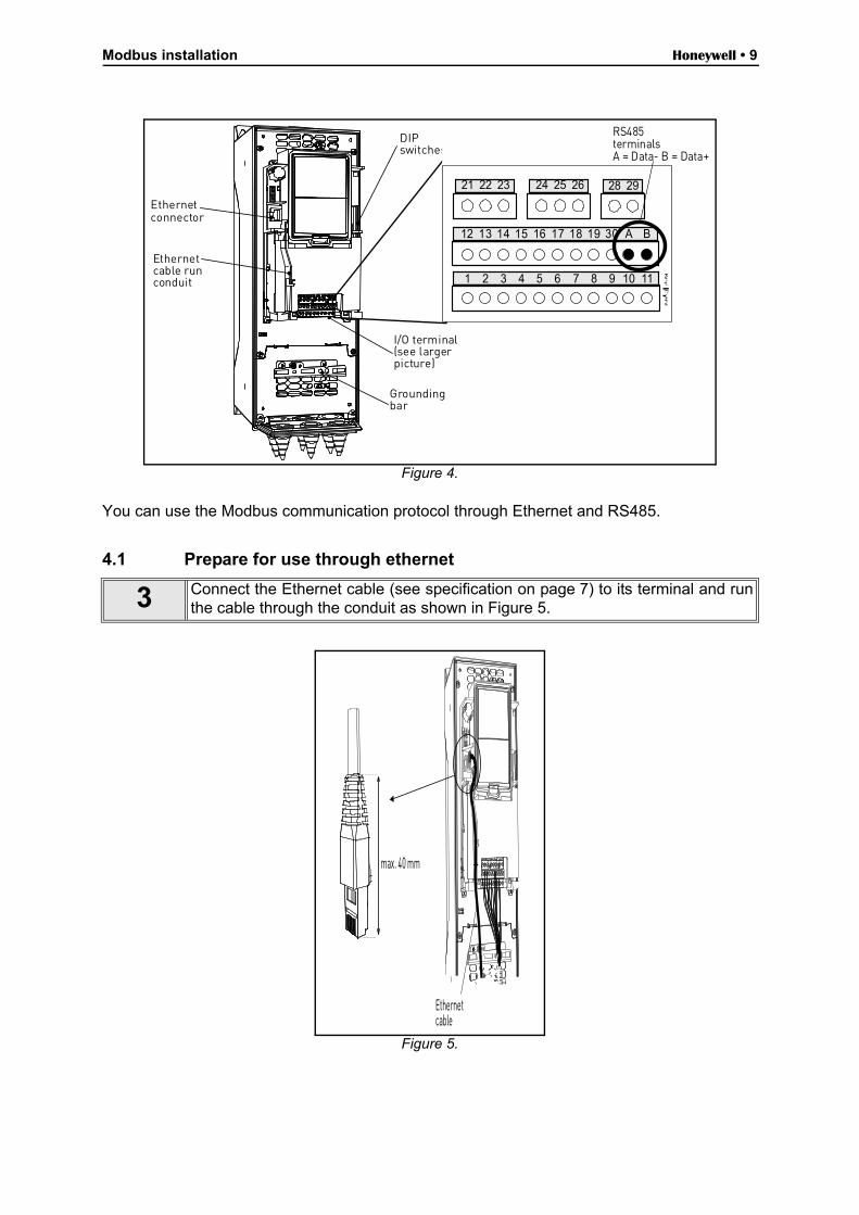
Figure 4.
You can use the Modbus communication protocol through Ethernet and RS485.
4.1 Prepare for use through ethernet
Figure 5.
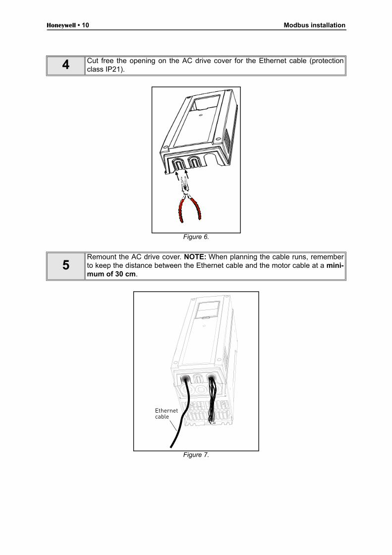
3 Connect the Ethernet cable (see specification on page 7) to its terminal and runthe cable through the conduit as shown in Figure 5.
Ethernetconnector
Ethernetcable runconduit
I/O terminal(see largerpicture)
Groundingbar
DIPswitches
28 29
12 13 14 15 16 17 18 19 30 BA
RS485terminalsA = Data- B = Data+
21 22 23 24 25 26
1 2 3 4 5 6 7 8 9 10 11
max. 40 mm
Ethernetcable
Honeywell • 10 Modbus installation
Figure 6.
Figure 7.
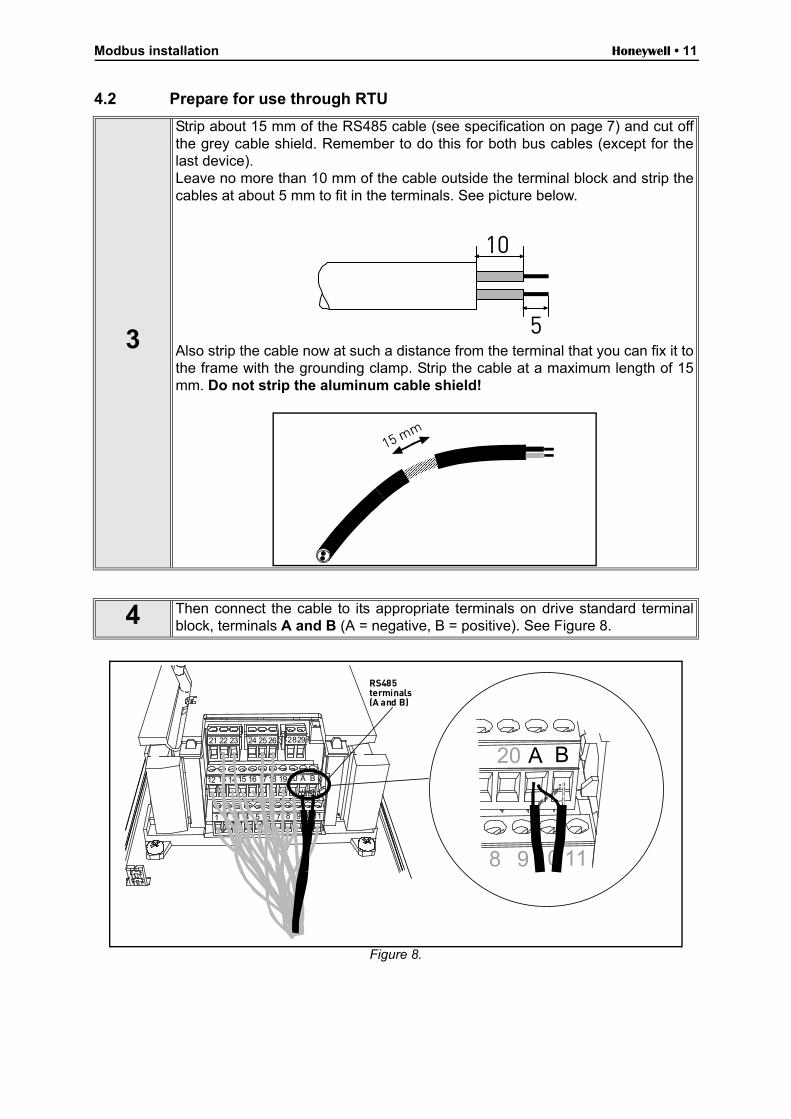
4 Cut free the opening on the AC drive cover for the Ethernet cable (protectionclass IP21).
5Remount the AC drive cover. NOTE: When planning the cable runs, rememberto keep the distance between the Ethernet cable and the motor cable at a mini-mum of 30 cm.
Ethernetcable
Modbus installation Honeywell • 11
4.2 Prepare for use through RTU
Figure 8.
3
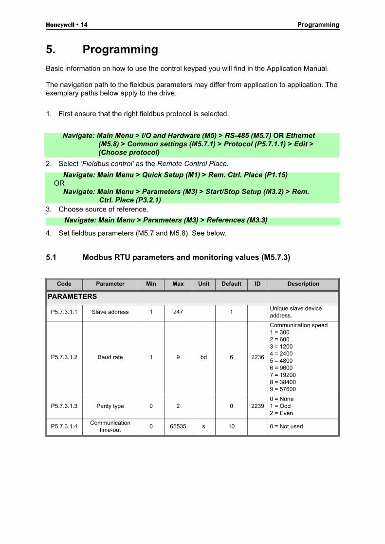
Strip about 15 mm of the RS485 cable (see specification on page 7) and cut offthe grey cable shield. Remember to do this for both bus cables (except for thelast device).Leave no more than 10 mm of the cable outside the terminal block and strip thecables at about 5 mm to fit in the terminals. See picture below.
Also strip the cable now at such a distance from the terminal that you can fix it tothe frame with the grounding clamp. Strip the cable at a maximum length of 15mm. Do not strip the aluminum cable shield!
4 Then connect the cable to its appropriate terminals on drive standard terminalblock, terminals A and B (A = negative, B = positive). See Figure 8.
10
5
B20 A
118 9 10
12 B13 14 15 16 17 18 19 20 A
1 112 3 4 5 6 7 8 9 10
21 22 23 24 25 26 2829
RS485terminals(A and B)

Honeywell • 12 Modbus installation
5
Using the cable clamp included in the delivery of the drive, ground the shield ofthe RS485 cable to the frame of the AC drive.
6
If drive is the last device on the bus, the bus termination must be set. Locatethe DIP switches to the right of the control keypad of the drive and turn the switchfor the RS485 bus termination resistor to position ON. Biasing is built in the ter-mination resistor. See also step 9 on page 13.
Cable clamp
RS485*
AO1AI2
AI1
OFFON
Current VoltageCurrent VoltageCurrent Voltage
* Bus termination resistor

Modbus installation Honeywell • 13
7
Unless already done for the other control cables,cut free the opening on the AC drive cover forthe RS485 cable (protection class IP21).
8
Remount the AC drive cover and run the RS485cables as shown in picture.NOTE: When planning the cable runs, remem-ber to keep the distance between the fieldbuscable and the motor cable at a minimum of 30cm.
9
The bus termination must be set for the first and the last device of the fieldbusline. See picture below. See also step 6 on page 12. We recommend that the firstdevice on the bus and, thus, terminated was the Master device.
RS485cables
Fieldbus
= Bus termination
Terminationactivated
Terminationactivated with
DIP switchTerminationdeactivated
Drive Drive Drive Drive Drive
Honeywell • 14 Programming
5. Programming
Basic information on how to use the control keypad you will find in the Application Manual.
The navigation path to the fieldbus parameters may differ from application to application. The exemplary paths below apply to the drive.
1. First ensure that the right fieldbus protocol is selected.
2. Select ‘Fieldbus control’ as the Remote Control Place.
3. Choose source of reference.
4. Set fieldbus parameters (M5.7 and M5.8). See below.
5.1 Modbus RTU parameters and monitoring values (M5.7.3)
Code Parameter Min Max Unit Default ID Description
PARAMETERS
P5.7.3.1.1 Slave address 1 247 1Unique slave device address.
P5.7.3.1.2 Baud rate 1 9 bd 6 2236
Communication speed1 = 3002 = 6003 = 12004 = 24005 = 48006 = 96007 = 192008 = 384009 = 57600
P5.7.3.1.3 Parity type 0 2 0 22390 = None1 = Odd2 = Even
P5.7.3.1.4Communication
time-out0 65535 s 10 0 = Not used
Navigate: Main Menu > I/O and Hardware (M5) > RS-485 (M5.7) OR Ethernet (M5.8) > Common settings (M5.7.1) > Protocol (P5.7.1.1) > Edit > (Choose protocol)
Navigate: Main Menu > Quick Setup (M1) > Rem. Ctrl. Place (P1.15)OR
Navigate: Main Menu > Parameters (M3) > Start/Stop Setup (M3.2) > Rem. Ctrl. Place (P3.2.1)
Navigate: Main Menu > Parameters (M3) > References (M3.3)

Programming Honeywell • 15
Table 4. Parameters related with Modbus used through RTU
MONITORING VALUES
P5.7.3.2.1Fieldbus protocol
status1 3 1
0 = Init1 = Stopped2 = Operational3 = Faulted
P5.7.3.2.2Communication
status0.0 99.999 0.0
0-99 Number of mes-sages with errors0-999 Number of mes-sages without communi-cation errors
P5.7.3.2.3 Illegal functions 0 See page 18.
P5.7.3.2.4Illegal data addresses
0 See page 18.
P5.7.3.2.5 Illegal data values 0 See page 18.
P5.7.3.2.6 Slave device busy 0 See page 18.
P5.7.3.2.7 Memory parity error 0 See page 18.
P5.7.3.2.8 Slave device failure 0 See page 18.
P5.7.3.2.9 Last fault response 0 See page 18.
P5.7.3.2.10 Control word hexSee page 25 and page 26.
P5.7.3.2.11 Status word hexSee page 25 and page 26.
Code Parameter Min Max Unit Default ID Description

Honeywell • 16 Programming
5.2 Modbus TCP parameters and monitoring values
5.2.1 Ethernet common settings (M5.8.1)
Table 5. Common settings for Modbus TCP (Ethernet)
5.2.2 Modbus TCP settings (M5.8.2)
* Will appear only after connection has been established
Table 6. Parameters related with Modbus used through Ethernet
Code Parameter Min Max Unit Default ID Description
P5.8.1.1 IP address mode See page 19.
P5.8.1.2 IP address See page 19.
P5.8.1.3 Subnet mask See page 19.
P5.8.1.4 Default gateway See page 19.
P5.8.1.5 MAC address See page 19.
Code Parameter Min Max Unit Default ID Description
PARAMETERS (Common settings M5.8.2.1)
P5.8.2.1.1 Connection limit 0 2 2Number of allowed con-nections
P5.8.2.1.2Unit identifier num-
ber0 255 1
See chapter 5.4.2 Mod-bus TCP settings
P5.8.2.1.3Communication
time-out0 65535 s 0 0 = Not used
MONITORING VALUES (Connection 1, Monitoring M5.8.2.2.1)*
P5.8.2.2.1.1Fieldbus protocol
status1 3
1 = Stopped2 = Operational3 = Faulted
P5.8.2.2.1.2Communication
status0.0 99.999 0.0
0-99 Number of mes-sages with errors0-999 Number of mes-sages without communi-cation errors
P5.8.2.2.1.3 Illegal functions 0 See page 21.
P5.8.2.2.1.4Illegal data addresses
0 See page 21.
P5.8.2.2.1.5 Illegal data values 0 See page 21.
P5.8.2.2.1.6 Slave device busy 0 See page 21.
P5.8.2.2.1.7 Memory parity error 0 See page 21.
P5.8.2.2.1.8 Slave device failure 0 See page 21.
P5.8.2.2.1.9 Last fault response 0 See page 21.
P5.8.2.2.1.10 Control word hex See page 25.
P5.8.2.2.1.11 Status word hex See page 26.
MONITORING VALUES (Connection 2, Monitoring M5.8.2.3.1)*
All parameters are the same as those for Connection 1.

Programming Honeywell • 17
5.3 Modbus RTU parameter descriptions
5.3.1 Modbus RTU Parameters
P5.7.3.1.1 SLAVE ADDRESS
Each slave must have a unique address (from 1 to 247) so that it can be addressed indepen-dently from other nodes.
P5.7.3.1.2 BAUD RATE
Select the communication speed for the network. The default value is 9600 baud.
P5.7.3.1.3 PARITY TYPE
Users can select the parity type for the network.
Table 7. Parity type
P5.7.3.1.4 COMMUNICATION TIME-OUT
Modbus board initiates a communication error for a time defined with this parameter. ‘0’ meansthat no fault is generated.
5.3.2 Modbus RTU monitoring values
P5.7.3.2.1 FIELDBUS PROTOCOL STATUS
Fieldbus Protocol Status tells the status of the protocol.
Table 8. FB protocol statuses
P5.7.3.2.2 COMMUNICATION STATUS
0The Communication status shows how many error and how many good messages the drivehas received. The Communication status includes a common error counter that counts CRCand parity errors and a counter for good messages.
Only messages to the current slave in use are counted in the good messages.
Parity type Stopbits
None 0
Odd 1
Even 2
INITIALIZING Protocol is starting up
STOPPED Protocol is timeouted or not used
OPERATIONAL Protocol is running
FAULTEDMajor fault in protocol, requires restarting.If fault remains call Honeywell Technical Support at 888-516-9347 “Option 4”.

Honeywell • 18 Programming
Table 9.
P5.7.3.2.3 ILLEGAL FUNCTIONS
The function code received in the query refers to an unallowed action for the server (or slave).
P5.7.3.2.4 ILLEGAL DATA ADDRESSES
The data address received in the query refers to an unallowed address for the server (or slave).
P5.7.3.2.5 ILLEGAL DATA VALUES
A value contained in the query data field refers to an unallowed value for server (or slave).
P5.7.3.2.6 SLAVE DEVICE BUSY
The server (or slave) is engaged in processing a long–duration program command. The client(or master) should retransmit the message later when the server (or slave) is free.
P5.7.3.2.7 MEMORY PARITY ERROR
The server (or slave) attempted to read record file but detected a parity error in the memory.
P5.7.3.2.8 SLAVE DEVICE FAILURE
An unrecoverable error occurred while the server (or slave) was attempting to perform the re-quested action.
P5.7.3.2.9 LAST FAULT RESPONSE
Shows the last fault response as Fault code.
P5.7.3.2.10 CONTROL WORD
Shows the Control Word received from the bus.
P5.7.3.2.11 STATUS WORD
Shows the current Status Word that is sent to the bus.
Good messages
0…999Number of messages received with-out errors
Bad Frames
0…99Number of messages received with errors
Programming Honeywell • 19
5.4 Modbus TCP parameter descriptions
5.4.1 Ethernet common settings
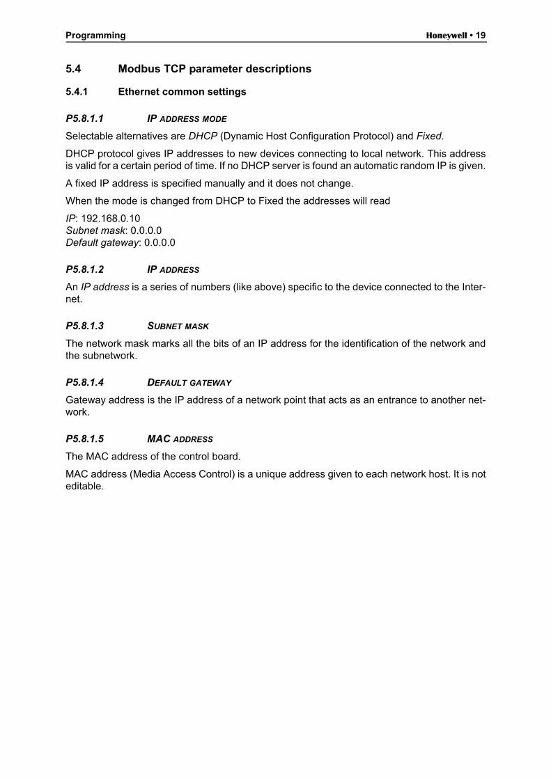
P5.8.1.1 IP ADDRESS MODE
Selectable alternatives are DHCP (Dynamic Host Configuration Protocol) and Fixed.
DHCP protocol gives IP addresses to new devices connecting to local network. This addressis valid for a certain period of time. If no DHCP server is found an automatic random IP is given.
A fixed IP address is specified manually and it does not change.
When the mode is changed from DHCP to Fixed the addresses will read
IP: 192.168.0.10Subnet mask: 0.0.0.0Default gateway: 0.0.0.0
P5.8.1.2 IP ADDRESS
An IP address is a series of numbers (like above) specific to the device connected to the Inter-net.
P5.8.1.3 SUBNET MASK
The network mask marks all the bits of an IP address for the identification of the network andthe subnetwork.
P5.8.1.4 DEFAULT GATEWAY
Gateway address is the IP address of a network point that acts as an entrance to another net-work.
P5.8.1.5 MAC ADDRESS
The MAC address of the control board.
MAC address (Media Access Control) is a unique address given to each network host. It is noteditable.
Honeywell • 20 Programming
5.4.2 Modbus TCP settings
5.4.2.1 Common settings
P5.8.2.1.1 CONNECTION LIMIT
Defines how many clients can access the server simultaneously.
P5.8.2.1.2 UNIT IDENTIFIER NUMBER
The Modbus ‘slave address’ field usually used on Modbus Serial Line is replaced by a singlebyte ‘Unit Identifier’.
On TCP/IP, the Modbus server is addressed using its IP address; therefore, the Modbus UnitIdentifier is useless.
P5.8.2.1.3 COMMUNICATION TIME-OUT
Modbus board initiates a communication error if the Ethernet connection is lost. Communica-tion time-out parameters define the minimum delay between packages received from the client.The timer is reset and started after each received package. This parameter can be used if theclient is periodically polling the slaves.
5.4.3 Modbus TCP monitoring values
These values will not appear before the connection is established.
5.4.3.1 Connection 1
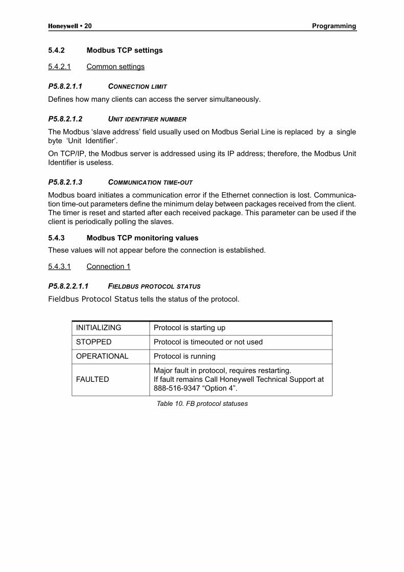
P5.8.2.2.1.1 FIELDBUS PROTOCOL STATUS
Fieldbus Protocol Status tells the status of the protocol.
Table 10. FB protocol statuses
INITIALIZING Protocol is starting up
STOPPED Protocol is timeouted or not used
OPERATIONAL Protocol is running
FAULTEDMajor fault in protocol, requires restarting.If fault remains Call Honeywell Technical Support at 888-516-9347 “Option 4”.

Programming Honeywell • 21
P5.8.2.2.1.2 COMMUNICATION STATUS
The Communication status shows how many error and how many good messages the drivehas received. The Communication status includes a common error counter that counts errorsand a counter for good messages.
Table 11. Communication status
P5.8.2.2.1.3 ILLEGAL FUNCTIONS
The function code received in the query refers to an unallowed action for the server (or slave).
P5.8.2.2.1.4 ILLEGAL DATA ADDRESSES
The data address received in the query refers to an unallowed address for the server (or slave).
P5.8.2.2.1.5 ILLEGAL DATA VALUES
A value contained in the query data field refers to an unallowed value for server (or slave).
P5.8.2.2.1.6 SLAVE DEVICE BUSY
The server (or slave) is engaged in processing a long–duration program command. The client(or master) should retransmit the message later when the server (or slave) is free.
P5.8.2.2.1.7 MEMORY PARITY ERROR
The server (or slave) attempted to read record file but detected a parity error in the memory.
P5.8.2.2.1.8 SLAVE DEVICE FAILURE
An unrecoverable error occurred while the server (or slave) was attempting to perform the re-quested action.
P5.8.2.2.1.9 LAST FAULT RESPONSE
Shows the last fault response as Fault code.
P5.8.2.2.1.10 CONTROL WORD
Shows the Control Word received from the bus.
P5.8.2.2.1.11 STATUS WORD
Shows the current Status Word that is sent to the bus.
5.4.3.2 Connection 2
The monitoring values are the same as those for Connection 1 (chapter 5.4.3.1), only with a different code (P5.8.2.3.1.X).
Good messages
0…999 Number of messages received without errors
Bad Frames
0…99 Number of messages received with errors
Honeywell • 22 Communications
6. Communications
Features of the Modbus-drive interface:
• Direct control of drive (e.g. Run, Stop, Direction, Speed reference, Fault reset)• Full access to all drive parameters• Monitor drive status (e.g. Output frequency, Output current, Fault code)
6.1 Data addresses in Modbus messages
All data addresses in Modbus messages are referenced to zero. The first occurrence of a dataitem is addressed as item number zero. For example:
• The coil known as ‘Coil 1’ in a programmable controller is addressed as ‘Coil 0000’ in the data address field of a Modbus message.
• Coil 127 decimal is addressed as ‘Coil 007E hex’ (126 decimal).• Holding register 40001 is addressed as register 0000 in the data address field of the
message. The function code field already specifies a ‘holding register’operation. There-fore the ‘4XXXX’ reference is implicit.
• Holding register 40108 is addressed as register 006B hex (107 decimal).
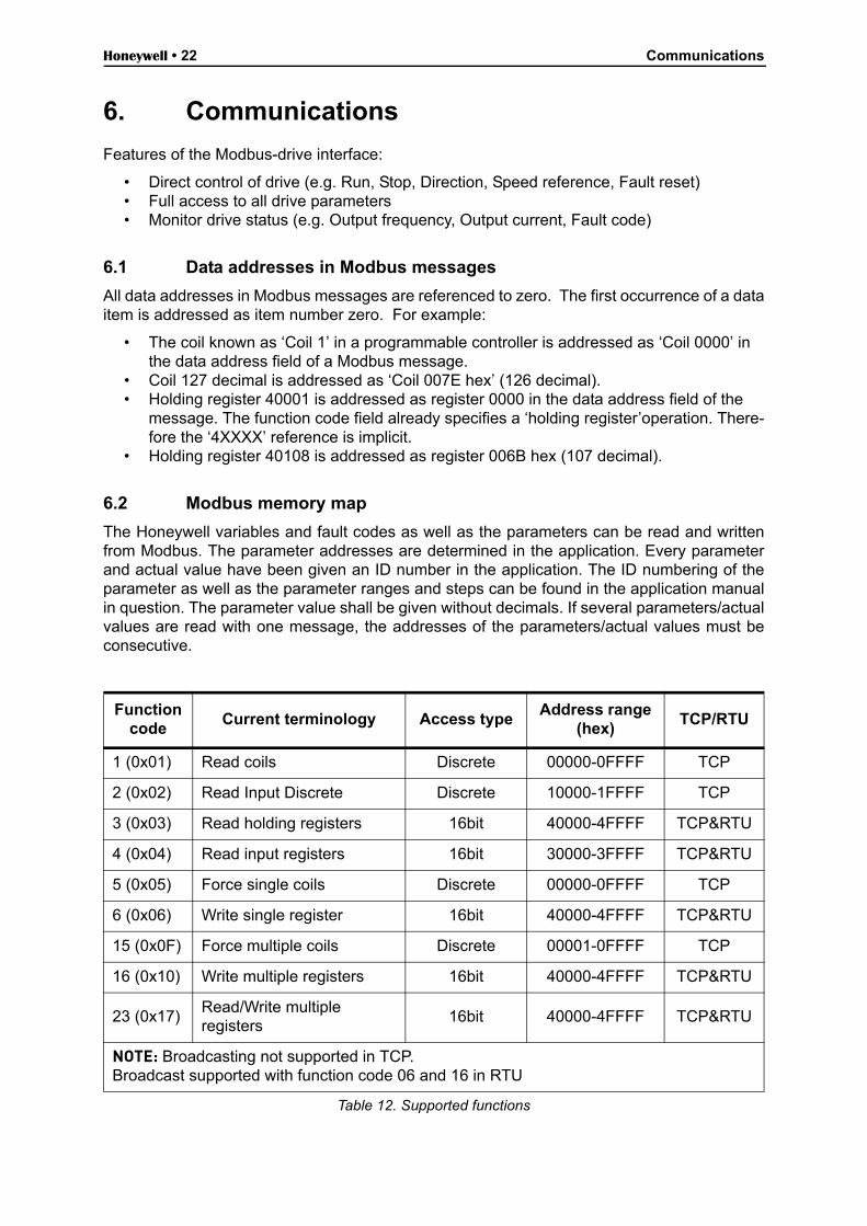
6.2 Modbus memory map
The Honeywell variables and fault codes as well as the parameters can be read and writtenfrom Modbus. The parameter addresses are determined in the application. Every parameterand actual value have been given an ID number in the application. The ID numbering of theparameter as well as the parameter ranges and steps can be found in the application manualin question. The parameter value shall be given without decimals. If several parameters/actualvalues are read with one message, the addresses of the parameters/actual values must beconsecutive.
Function code
Current terminology Access typeAddress range
(hex)TCP/RTU
1 (0x01) Read coils Discrete 00000-0FFFF TCP
2 (0x02) Read Input Discrete Discrete 10000-1FFFF TCP
3 (0x03) Read holding registers 16bit 40000-4FFFF TCP&RTU
4 (0x04) Read input registers 16bit 30000-3FFFF TCP&RTU
5 (0x05) Force single coils Discrete 00000-0FFFF TCP
6 (0x06) Write single register 16bit 40000-4FFFF TCP&RTU
15 (0x0F) Force multiple coils Discrete 00001-0FFFF TCP
16 (0x10) Write multiple registers 16bit 40000-4FFFF TCP&RTU
23 (0x17)Read/Write multiple registers
16bit 40000-4FFFF TCP&RTU
NOTE: Broadcasting not supported in TCP.Broadcast supported with function code 06 and 16 in RTU
Table 12. Supported functions
Communications Honeywell • 23
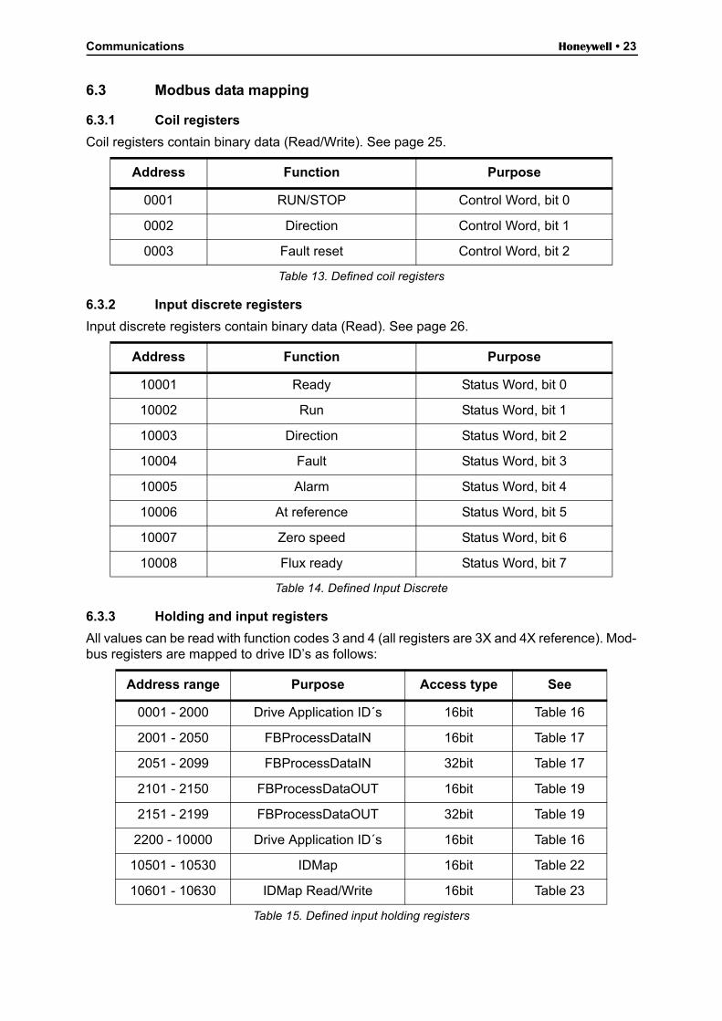
6.3 Modbus data mapping
6.3.1 Coil registers
Coil registers contain binary data (Read/Write). See page 25.
6.3.2 Input discrete registers
Input discrete registers contain binary data (Read). See page 26.
6.3.3 Holding and input registers
All values can be read with function codes 3 and 4 (all registers are 3X and 4X reference). Mod-bus registers are mapped to drive ID’s as follows:
Address Function Purpose
0001 RUN/STOP Control Word, bit 0
0002 Direction Control Word, bit 1
0003 Fault reset Control Word, bit 2
Table 13. Defined coil registers
Address Function Purpose
10001 Ready Status Word, bit 0
10002 Run Status Word, bit 1
10003 Direction Status Word, bit 2
10004 Fault Status Word, bit 3
10005 Alarm Status Word, bit 4
10006 At reference Status Word, bit 5
10007 Zero speed Status Word, bit 6
10008 Flux ready Status Word, bit 7
Table 14. Defined Input Discrete
Address range Purpose Access type See
0001 - 2000 Drive Application ID´s 16bit Table 16
2001 - 2050 FBProcessDataIN 16bit Table 17
2051 - 2099 FBProcessDataIN 32bit Table 17
2101 - 2150 FBProcessDataOUT 16bit Table 19
2151 - 2199 FBProcessDataOUT 32bit Table 19
2200 - 10000 Drive Application ID´s 16bit Table 16
10501 - 10530 IDMap 16bit Table 22
10601 - 10630 IDMap Read/Write 16bit Table 23
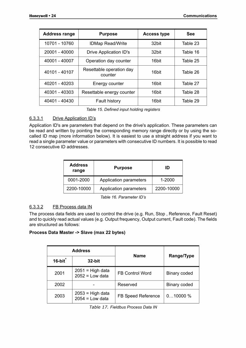
Table 15. Defined input holding registers
Honeywell • 24 Communications
6.3.3.1 Drive Application ID’s
Application ID's are parameters that depend on the drive's application. These parameters canbe read and written by pointing the corresponding memory range directly or by using the so-called ID map (more information below). It is easiest to use a straight address if you want toread a single parameter value or parameters with consecutive ID numbers. It is possible to read12 consecutive ID addresses.
6.3.3.2 FB Process data IN
The process data fields are used to control the drive (e.g. Run, Stop , Reference, Fault Reset)and to quickly read actual values (e.g. Output frequency, Output current, Fault code). The fieldsare structured as follows:
Process Data Master -> Slave (max 22 bytes)
10701 - 10760 IDMap Read/Write 32bit Table 23
20001 - 40000 Drive Application ID's 32bit Table 16
40001 - 40007 Operation day counter 16bit Table 25
40101 - 40107Resettable operation day
counter16bit Table 26
40201 - 40203 Energy counter 16bit Table 27
40301 - 40303 Resettable energy counter 16bit Table 28
40401 - 40430 Fault history 16bit Table 29
Address range
Purpose ID
0001-2000 Application parameters 1-2000
2200-10000 Application parameters 2200-10000
Table 16. Parameter ID’s
AddressName Range/Type
16-bit* 32-bit
20012051 = High data2052 = Low data
FB Control Word Binary coded
2002 - Reserved Binary coded
20032053 = High data2054 = Low data
FB Speed Reference 0…10000 %
Table 17. Fieldbus Process Data IN
Address range Purpose Access type See
Table 15. Defined input holding registers

Communications Honeywell • 25
Control word bits
The Control word is composed of 32 bits. Meanings of bits are described below. Unused bitshave to be set to zero.
Table 18. Control Word bits
20042055 = High data2056 = Low data
FB Process Data In 1 See chapter 9
20052057 = High data2058 = Low data
FB Process Data In 2 See chapter 9
20062059 = High data2060 = Low data
FB Process Data In 3 See chapter 9
20072061 = High data2062 = Low data
FB Process Data In 4 See chapter 9
20082063 = High data2064 = Low data
FB Process Data In 5 See chapter 9
20092065 = High data2066 = Low data
FB Process Data In 6 See chapter 9
20102067 = High data2068 = Low data
FB Process Data In 7 See chapter 9
20112069 = High data2070 = Low data
FB Process Data In 8 See chapter 9
* . In drive, the Control Word and the Status Word are formed of 32 bits. Only the initial 16 bits can be read in the 16-bit area.
Bit Name Value = 1 Value = 0 Description
B0 Start/Stop Start request Stop requestStart/Stop command to application
B1 Direction Reverse ForwardCommand to changerotational direction
B2 Fault reset Reset faults No action Command to reset fault
B3-B31 Not used
AddressName Range/Type
16-bit* 32-bit
Table 17. Fieldbus Process Data IN
Honeywell • 26 Communications
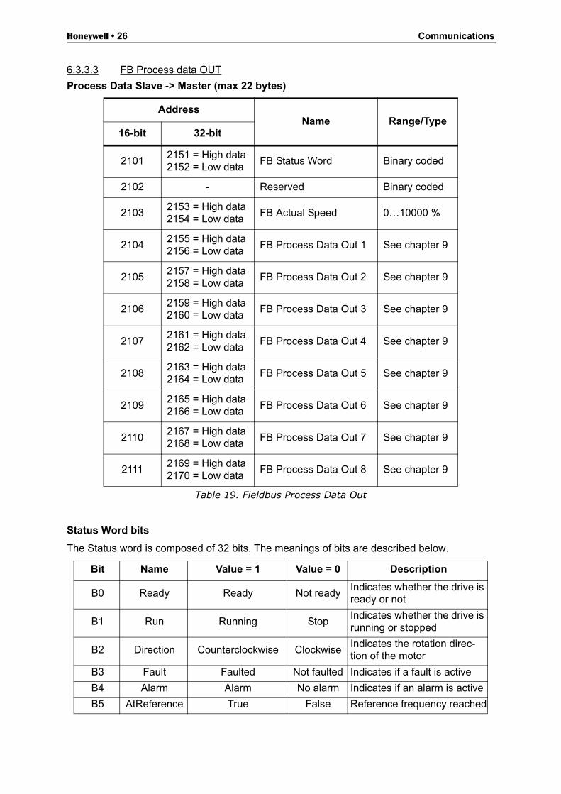
6.3.3.3 FB Process data OUT
Process Data Slave -> Master (max 22 bytes)
Status Word bits
The Status word is composed of 32 bits. The meanings of bits are described below.
AddressName Range/Type
16-bit 32-bit
21012151 = High data2152 = Low data
FB Status Word Binary coded
2102 - Reserved Binary coded
21032153 = High data2154 = Low data
FB Actual Speed 0…10000 %
21042155 = High data2156 = Low data
FB Process Data Out 1 See chapter 9
21052157 = High data2158 = Low data
FB Process Data Out 2 See chapter 9
21062159 = High data2160 = Low data
FB Process Data Out 3 See chapter 9
21072161 = High data2162 = Low data
FB Process Data Out 4 See chapter 9
21082163 = High data2164 = Low data
FB Process Data Out 5 See chapter 9
21092165 = High data2166 = Low data
FB Process Data Out 6 See chapter 9
21102167 = High data2168 = Low data
FB Process Data Out 7 See chapter 9
21112169 = High data2170 = Low data
FB Process Data Out 8 See chapter 9
Table 19. Fieldbus Process Data Out
Bit Name Value = 1 Value = 0 Description
B0 Ready Ready Not readyIndicates whether the drive is ready or not
B1 Run Running StopIndicates whether the drive is running or stopped
B2 Direction Counterclockwise ClockwiseIndicates the rotation direc-tion of the motor
B3 Fault Faulted Not faulted Indicates if a fault is active
B4 Alarm Alarm No alarm Indicates if an alarm is active
B5 AtReference True False Reference frequency reached

Communications Honeywell • 27
Table 20. Status Word bits B1-B28
Table 21. Status Word bits B29-B31, descriptions of bit connections
The use of process data depends on the application. In a typical situation, the device is startedand stopped with the ControlWord (CW) written by the Master and the Rotating speed is setwith Reference (REF). With PD1…PD8 the device can be given other reference values (e.g.Torque reference).
With the StatusWord (SW) read by the Master, the status of the device can be seen. ActualValue (ACT) and PD1…PD8 show the other actual values.
6.3.3.4 ID map
Using the ID map, you can read consecutive memory blocks that contain parameters whoseID's are not in a consecutive order. The address range 10501 - 10530 is called 'IDMap', and itincludes an address map in which you can write your parameter ID's in any order. The addressrange 10601 to 10630 is called 'IDMap Read/Write,' and it includes values for parameters writ-ten in the IDMap. As soon as one ID number has been written in the map cell 10501, the cor-responding parameter value can be read and written in the address 10601, and so on.
Table 22. IDMap initialization
B6 ZeroSpeed True False Motor running at zero speed
B7 FluxReady True False Motor is magnetized
B8-B28 Not used
B29 Control place
B30 Control place
B31 Control place
Description
0 0 1 Fieldbus
0 1 0 Keypad
0 1 1 PC tool
1 0 0 I/O terminals
Address Data
410501 700
410502 702
410503 707
410504 704
Parameter ID’s
ID699
700701702
703704705
706707
708
Honeywell • 28 Communications
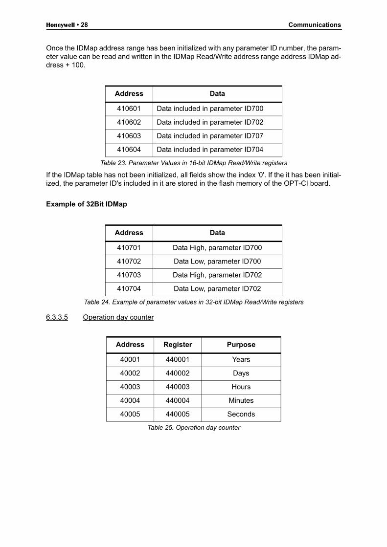
Once the IDMap address range has been initialized with any parameter ID number, the param-eter value can be read and written in the IDMap Read/Write address range address IDMap ad-dress + 100.
If the IDMap table has not been initialized, all fields show the index '0'. If the it has been initial-ized, the parameter ID's included in it are stored in the flash memory of the OPT-CI board.
Example of 32Bit IDMap
6.3.3.5 Operation day counter
Address Data
410601 Data included in parameter ID700
410602 Data included in parameter ID702
410603 Data included in parameter ID707
410604 Data included in parameter ID704
Table 23. Parameter Values in 16-bit IDMap Read/Write registers
Address Data
410701 Data High, parameter ID700
410702 Data Low, parameter ID700
410703 Data High, parameter ID702
410704 Data Low, parameter ID702
Table 24. Example of parameter values in 32-bit IDMap Read/Write registers
Address Register Purpose
40001 440001 Years
40002 440002 Days
40003 440003 Hours
40004 440004 Minutes
40005 440005 Seconds
Table 25. Operation day counter
Communications Honeywell • 29
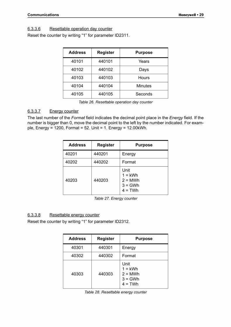
6.3.3.6 Resettable operation day counter
Reset the counter by writing “1” for parameter ID2311.
6.3.3.7 Energy counter
The last number of the Format field indicates the decimal point place in the Energy field. If thenumber is bigger than 0, move the decimal point to the left by the number indicated. For exam-ple, Energy = 1200, Format = 52. Unit = 1. Energy = 12.00kWh.
6.3.3.8 Resettable energy counter
Reset the counter by writing “1” for parameter ID2312.
Address Register Purpose
40101 440101 Years
40102 440102 Days
40103 440103 Hours
40104 440104 Minutes
40105 440105 Seconds
Table 26. Resettable operation day counter
Address Register Purpose
40201 440201 Energy
40202 440202 Format
40203 440203
Unit1 = kWh2 = MWh3 = GWh4 = TWh
Table 27. Energy counter
Address Register Purpose
40301 440301 Energy
40302 440302 Format
40303 440303
Unit1 = kWh2 = MWh3 = GWh4 = TWh
Table 28. Resettable energy counter

Honeywell • 30 Communications
6.3.3.9 Fault history
The fault history can be viewed by reading from address 40401 onward. The faults are listed inchronological order so that the latest fault is mentioned first and the oldest last. The fault historycan contain 29 faults at the same time. The fault history contents are represented as follows.
Address Register Purpose
40401 440401
40402 440402
40403 440403
... ...
40429 440429
Table 29. Fault history
Communications Honeywell • 31
A
F
D
.
E
C
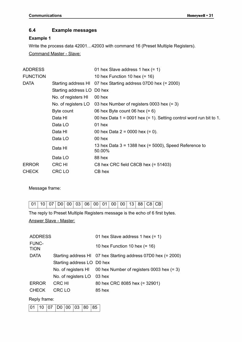
6.4 Example messages
Example 1
Write the process data 42001…42003 with command 16 (Preset Multiple Registers).
Command Master - Slave:
Message frame:
The reply to Preset Multiple Registers message is the echo of 6 first bytes.
Answer Slave - Master:
Reply frame:
DDRESS 01 hex Slave address 1 hex (= 1)
UNCTION 10 hex Function 10 hex (= 16)
ATA Starting address HI 07 hex Starting address 07D0 hex (= 2000)
Starting address LO D0 hex
No. of registers HI 00 hex
No. of registers LO 03 hex Number of registers 0003 hex (= 3)
Byte count 06 hex Byte count 06 hex (= 6)
Data HI 00 hex Data 1 = 0001 hex (= 1). Setting control word run bit to 1
Data LO 01 hex
Data HI 00 hex Data 2 = 0000 hex (= 0).
Data LO 00 hex
Data HI13 hex Data 3 = 1388 hex (= 5000), Speed Reference to 50.00%
Data LO 88 hex
RROR CRC HI C8 hex CRC field C8CB hex (= 51403)
HECK CRC LO CB hex
01 10 07 D0 00 03 06 00 01 00 00 13 88 C8 CB
ADDRESS 01 hex Slave address 1 hex (= 1)
FUNC-TION
10 hex Function 10 hex (= 16)
DATA Starting address HI 07 hex Starting address 07D0 hex (= 2000)
Starting address LO D0 hex
No. of registers HI 00 hex Number of registers 0003 hex (= 3)
No. of registers LO 03 hex
ERROR CRC HI 80 hex CRC 8085 hex (= 32901)
CHECK CRC LO 85 hex
01 10 07 D0 00 03 80 85

Honeywell • 32 Communications
Example 2:
Read the Process Data 42103…42104 with command 4 (Read Input Registers).
Command Master - Slave:
Message frame:
The reply to the Read Input Registers message contains the values of the read registers.
Answer Slave - Master:
Reply frame:
ADDRESS 01 hex Slave address 1 hex (= 1)
FUNCTION 04 hex Function 4 hex (= 4)
DATA Starting address HI 08 hex
Starting address LO 36 hex
No. of registers HI 00 hex Number of registers 0002 hex (= 2)
No. of registers LO 02 hex
ERROR CRC HI 93 hex CRC field 93A5 hex (= 37797)
CHECK CRC LO A5 hex
01 04 08 36 00 02 93 A5
ADDRESS 01 hex Slave address 1 hex (= 1)
FUNCTION 04 hex Function 4 hex (= 4)
DATA Byte count 04 hex Byte count 4 hex (= 4)
Data HI 13 hex Speed reference = 1388 hex (=5000 => 50.00%)
Data LO 88 hex
Data HI 09 hex Output Frequency = 09C4 hex (=2500 =>25.00Hz)
Data LO C4 hex
ERROR CRC HI 78 hexCRC field 78E9 hex (=30953)
CHECK CRC LO E9 hex
01 04 04 13 88 09 C4 78 E9

Communications Honeywell • 33
Example of an exception response
In an exception response, the Slave sets the most-significant bit (MSB) of the function code to1. The Slave returns an exception code in the data field.
Command Master - Slave:
Message frame:
Exception response:
Answer Slave - Master:
Reply frame:
ADDRESS 01 hex Slave address 1 hex (= 1)
FUNCTION 04 hex Function 4 hex (= 4)
DATA Starting address HI 17 hex Starting address 1770 hex (= 6000)
Starting address LO 70 hex
No. of registers HI 00 hex Invalid number of registers 0005 hex (= 5)
No. of registers LO 05 hex
ERROR CRC HI 34 hex
CHECK CRC LO 66 hex CRC field 3466 hex (=13414)
01 04 17 70 00 05 34 66
ADDRESS 01 hex Slave address 1 hex (= 1)
FUNCTION 84 hex Most significant bit set to 1
ERROR CODE 04 hex Error code 04 => Slave Device Failure
ERROR CRC HI 42 hex CRC field 42C3 hex (= 17091)
CHECK CRC LO C3 hex
01 84 04 42 C3
Honeywell • 34 Fault tracing
7. Fault tracing
When an unusual operating condition is detected by the AC drive control diagnostics, the driveinitiates a notification visible, for example, on the keypad. The keypad will show the ordinalnumber of the fault, the fault code and a short fault description.
The fault can be reset with the Reset button on the control keypad or via the I/O terminal. Thefaults are stored in the Fault history menu which can be browsed. The different fault codes youwill find in the table below. This fault table presents only the faults related to the fieldbus in use.
Note: When contacting distributor or factory because of a fault condition, always write down alltexts and codes on the keypad display and call Honeywell Technical Support at 888-516-9347“Option 4”.
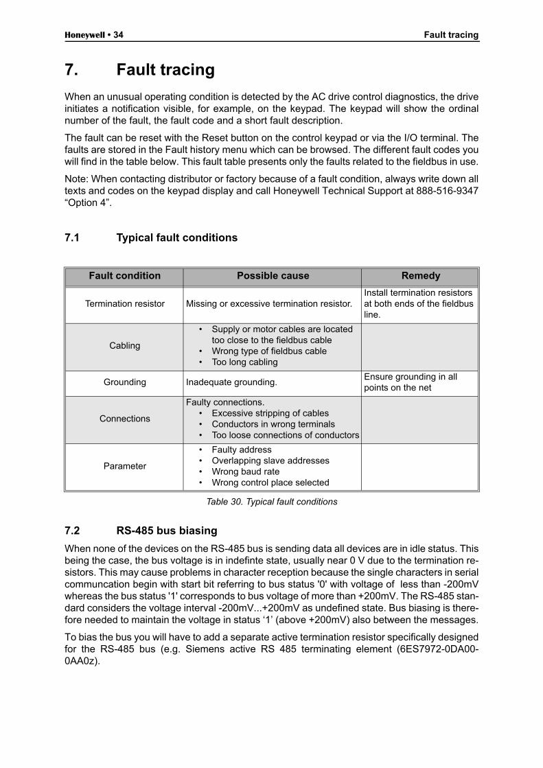
7.1 Typical fault conditions
Table 30. Typical fault conditions
7.2 RS-485 bus biasing
When none of the devices on the RS-485 bus is sending data all devices are in idle status. Thisbeing the case, the bus voltage is in indefinte state, usually near 0 V due to the termination re-sistors. This may cause problems in character reception because the single characters in serialcommuncation begin with start bit referring to bus status '0' with voltage of less than -200mVwhereas the bus status '1' corresponds to bus voltage of more than +200mV. The RS-485 stan-dard considers the voltage interval -200mV...+200mV as undefined state. Bus biasing is there-fore needed to maintain the voltage in status ‘1’ (above +200mV) also between the messages.
To bias the bus you will have to add a separate active termination resistor specifically designedfor the RS-485 bus (e.g. Siemens active RS 485 terminating element (6ES7972-0DA00-0AA0z).
Fault condition Possible cause Remedy
Termination resistor Missing or excessive termination resistor.Install termination resistors at both ends of the fieldbus line.
Cabling
• Supply or motor cables are located too close to the fieldbus cable
• Wrong type of fieldbus cable• Too long cabling
Grounding Inadequate grounding.Ensure grounding in all points on the net
Connections
Faulty connections.• Excessive stripping of cables• Conductors in wrong terminals• Too loose connections of conductors
Parameter
• Faulty address• Overlapping slave addresses• Wrong baud rate• Wrong control place selected
Fault tracing Honeywell • 35
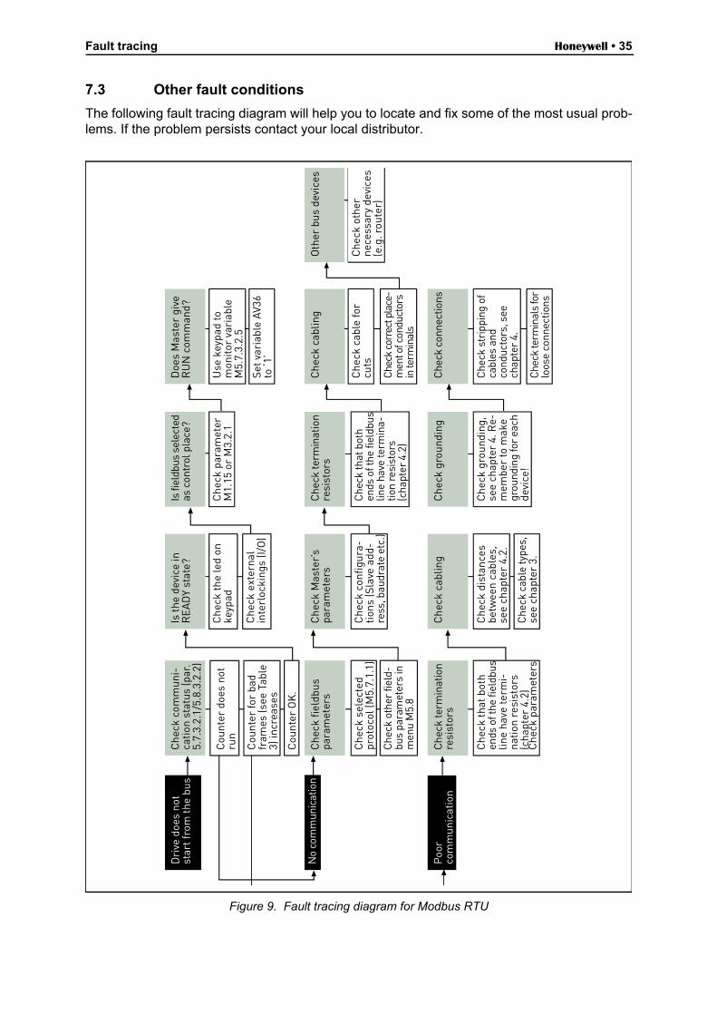
7.3 Other fault conditions
The following fault tracing diagram will help you to locate and fix some of the most usual prob-lems. If the problem persists contact your local distributor.
Figure 9. Fault tracing diagram for Modbus RTU
Dri
ve d
oes
not
star
t fro
m th
e bu
sC
heck
com
mun
i-ca
tion
stat
us (p
ar.
5.7.
3.2.
1/5.
8.3.
2.2)
Cou
nter
doe
s no
tru
n
Cou
nter
for
bad
fram
es (s
ee T
able
3) in
crea
ses
Cou
nter
OK
.
No
com
mun
icat
ion
Poo
rco
mm
unic
atio
n
Is th
e de
vice
inR
EAD
Y st
ate?
Che
ck th
e le
d on
keyp
ad
Che
ck e
xter
nal
inte
rloc
king
s (I/
O)
Is fi
eldb
us s
elec
ted
as c
ontr
ol p
lace
?
Che
ck p
aram
eter
M1.
15 o
r M
3.2.
1
Doe
s M
aste
r gi
veR
UN
com
man
d?
Use
key
pad
tom
onito
r va
riab
leM
5.7.
3.2.
5
Set v
aria
ble
AV36
to ‘1
’
Che
ck fi
eldb
uspa
ram
eter
s
Che
ck o
ther
fiel
d-bu
s pa
ram
eter
s in
men
u M
5.8
Che
ck s
elec
ted
prot
ocol
(M5.
7.1.
1)
Che
ck M
aste
r’s
para
met
ers
Che
ck c
onfig
ura-
tions
(Sla
ve a
dd-
ress
, bau
drat
e et
c.)
Che
ck te
rmin
atio
nre
sist
ors
Che
ck th
at b
oth
ends
of t
he fi
eldb
uslin
e ha
ve te
rmin
a-tio
n re
sist
ors
(cha
pter
4.2
)
Che
ck c
ablin
g
Che
ck c
able
for
cuts
Chec
k co
rrec
t pla
ce-
men
t of c
ondu
ctor
sin
term
inal
s
Oth
er b
us d
evic
es
Che
ck o
ther
nece
ssar
y de
vice
s(e
.g. r
oute
r)
Che
ck te
rmin
atio
nre
sist
ors
Che
ck th
at b
oth
ends
of t
he fi
eldb
uslin
e ha
ve te
rmi-
natio
n re
sist
ors
(cha
pter
4.2
)C
heck
par
amet
ers
Che
ck c
ablin
g
Che
ck d
ista
nces
betw
een
cabl
es,
see
chap
ter
4.2.
Che
ck c
able
type
s,se
e ch
apte
r 3.
Che
ck g
roun
ding
Che
ck g
roun
ding
,se
e ch
apte
r 4.
Re-
mem
ber
to m
ake
grou
ndin
g fo
r ea
chde
vice
!
Che
ck c
onne
ctio
ns
Che
ck s
trip
ping
of
cabl
es a
ndco
nduc
tors
, see
chap
ter
4.
Chec
k te
rmin
als
for
loos
e co
nnec
tions
Honeywell • 36 Fault tracing
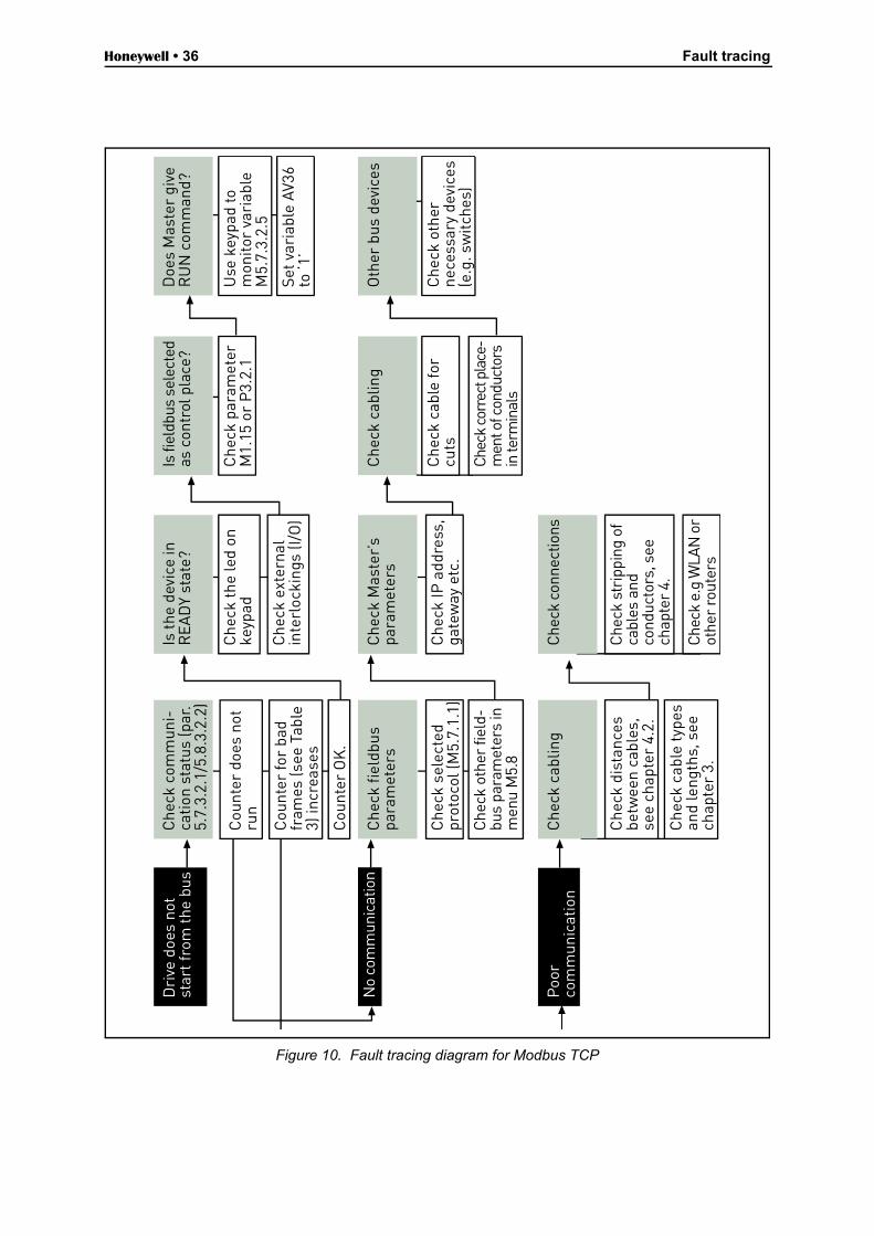
Figure 10. Fault tracing diagram for Modbus TCP
Dri
ve d
oes
not
star
t fro
m th
e bu
sC
heck
com
mun
i-ca
tion
stat
us (p
ar.
5.7.
3.2.
1/5.
8.3.
2.2)
Cou
nter
doe
s no
tru
n
Cou
nter
for
bad
fram
es (s
ee T
able
3) in
crea
ses
Cou
nter
OK
.
No
com
mun
icat
ion
Poo
rco
mm
unic
atio
n
Is th
e de
vice
inR
EAD
Y st
ate?
Che
ck th
e le
d on
keyp
ad
Che
ck e
xter
nal
inte
rloc
king
s (I/
O)
Is fi
eldb
us s
elec
ted
as c
ontr
ol p
lace
?
Che
ck p
aram
eter
M1.
15 o
r P
3.2.
1
Doe
s M
aste
r gi
veR
UN
com
man
d?
Use
key
pad
tom
onito
r va
riab
leM
5.7.
3.2.
5
Set v
aria
ble
AV36
to ‘1
’
Che
ck fi
eldb
uspa
ram
eter
s
Che
ck o
ther
fiel
d-bu
s pa
ram
eter
s in
men
u M
5.8
Che
ck s
elec
ted
prot
ocol
(M5.
7.1.
1)
Che
ck M
aste
r’s
para
met
ers
Che
ck IP
add
ress
,ga
tew
ay e
tc.
Che
ck c
ablin
g
Che
ck c
able
for
cuts
Chec
k co
rrec
t pla
ce-
men
t of c
ondu
ctor
sin
term
inal
s
Oth
er b
us d
evic
es
Che
ck o
ther
nece
ssar
y de
vice
s(e
.g. s
witc
hes)
Che
ck c
ablin
g
Che
ck d
ista
nces
betw
een
cabl
es,
see
chap
ter
4.2.
Che
ck c
able
type
san
d le
ngth
s, s
eech
apte
r 3.
Che
ck c
onne
ctio
ns
Che
ck s
trip
ping
of
cabl
es a
ndco
nduc
tors
, see
chap
ter
4.
Chec
k e.
g W
LAN
or
othe
r ro
uter
s
Quick setup Honeywell • 37
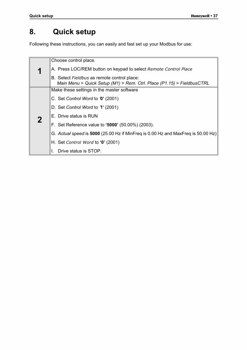
8. Quick setup
Following these instructions, you can easily and fast set up your Modbus for use:
1
Choose control place.
A. Press LOC/REM button on keypad to select Remote Control Place
B. Select Fieldbus as remote control place: Main Menu > Quick Setup (M1) > Rem. Ctrl. Place (P1.15) > FieldbusCTRL
2
Make these settings in the master software
C. Set Control Word to ‘0’ (2001)
D. Set Control Word to ‘1’ (2001)
E. Drive status is RUN
F. Set Reference value to ‘5000’ (50.00%) (2003).
G. Actual speed is 5000 (25.00 Hz if MinFreq is 0.00 Hz and MaxFreq is 50.00 Hz)
H. Set Control Word to ‘0’ (2001)
I. Drive status is STOP.
Honeywell • 38 Annex
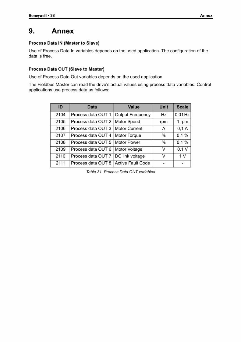
9. Annex
Process Data IN (Master to Slave)
Use of Process Data In variables depends on the used application. The configuration of the data is free.
Process Data OUT (Slave to Master)
Use of Process Data Out variables depends on the used application.
The Fieldbus Master can read the drive’s actual values using process data variables. Control applications use process data as follows:
Table 31. Process Data OUT variables
ID Data Value Unit Scale
2104 Process data OUT 1 Output Frequency Hz 0,01 Hz
2105 Process data OUT 2 Motor Speed rpm 1 rpm
2106 Process data OUT 3 Motor Current A 0,1 A
2107 Process data OUT 4 Motor Torque % 0,1 %
2108 Process data OUT 5 Motor Power % 0,1 %
2109 Process data OUT 6 Motor Voltage V 0,1 V
2110 Process data OUT 7 DC link voltage V 1 V
2111 Process data OUT 8 Active Fault Code - -

Automation and Control SolutionsHoneywell International Inc.1985 Douglas Drive NorthGolden Valley, MN 55422
Honeywell Limited-Honeywell Limitée35 Dynamic DriveToronto, Ontario M1V 4Z9customer.honeywell.com
® U.S. Registered Trademark© 2011 Honeywell International Inc.62-0351—01 M.S. 01-11 Printed in U.S.A.