installation gas slide-in range instructions...
TRANSCRIPT

TOOLS YOU WILL NEED
MATERIALS YOU MAY NEED
1
Questions? Call 800.GE.CARES (800.432.2737) or Visit our Website at: ge.com
Installation Gas Slide-In RangeInstructions JGSP28
BEFORE YOU BEGIN
Read these instructions completely and carefully.
• IMPORTANT — Save theseinstructions for local inspector’s use.
• IMPORTANT — Observe allgoverning codes and ordinances.
• Note to Installer – Be sure to leave theseinstructions with the Consumer.
• Note to Consumer – Keep theseinstructions for future reference.
• Product failure due to improper installationis not covered under the Warranty.
WARNING — This appliance mustbe properly grounded.
• IMPORTANT — Leak testing of theappliance shall be conducted according tothe manufacturer’s instructions.
• Proper installation is the responsibility of the installer and product failure due toimproper installation is NOT covered underwarranty.
IN THE COMMONWEALTH OFMASSACHUSETTS:
• This product must be installed by alicensed plumber or gas fitter.
• When using ball-type gas shut-off valves,they shall be the T-handle type.
• A flexible gas connector, when used, mustnot exceed 3 feet.
PARTS INCLUDED
Anti-Tip Bracket
Shut Off ValvePipe Fittings
CSA-Approved Flexible Gas Line 3/8″ Min. ID, 1/2″ NPT Connection,
3-foot Maximum Length (Massachusetts Only)
Joint Sealant
Wrench or Pliers (for 1-7/16” Nut)
Level1/4” Nut Driver
Safety Glasses Drill
Tape Measure
Screws
Rear Filler 2 Screws
Phillips HeadScrewdriver
Pipe Wrench
31-10598-2 1-07 JR

FOR YOUR SAFETY:
WARNING — If the information in this manual is not followed exactly, a fire,explosion or gas leak may result, causingproperty damage, personal injury or death.
Do not store or use gasoline or otherflammable vapors and liquids in the vicinityof this or any other appliance!
WHAT TO DO IF YOUSMELL GAS:
• Do not try to light any appliance. Do nottouch any electrical switch; do not use anyphone in your building.
• Immediately call your gas supplier from aneighbor’s phone. Follow the gas supplier’sinstructions.
• If you cannot reach your gas supplier, callthe fire department.
Installation and service must be performed bya qualified installer, service agency or the gassupplier.
2
Installation Instructions
IMPORTANT SAFETY INSTRUCTIONS
This range has been design certified byUNDERWRITERS LABORATORIES. You’ll findsafety precautions in your Owner’s Manual.Read them carefully.
• Installation of this range must conform withlocal codes or in the absence of local codeswith the National Fuel Gas Code, ANSIZ223.1–Latest edition.
• Be sure your range is installed properly bya qualified installer or service technician.
• To eliminate reaching over surface burners,cabinet storage above burner should beavoided.
• Do not install the unit near an outside dooror where a draft may affect its use.

3
Installation Instructions
ANTI-TIP DEVICE
WARNING — To reduce the risk of tipping, the appliance must be secured by properly installed Anti-Tip bracket packedwith this appliance.To check if the bracket is installed andengaged properly, carefully tip the rangeforward. The anti-tip bracket should engageand prevent the range from tipping over.
WARNING —
• All ranges can tip
• Injury to persons could result
• Install Anti-Tip bracket packedwith range
• See Installation Instructions
If you pull the range out and away from thewall for any reason, make sure the Anti-Tipbracket is engaged when the range is pushedback against the wall.
ELECTRICAL REQUIRMENTSThis appliance must be supplied with theproper voltage and frequency and connectedto an individual, properly grounded branchcircuit, protected by a circuit breaker or fusehaving amperage as noted on the ratingplate. (Rating plate is located above thestorage drawer below the oven frame).
We recommend you have the electrical wiringand hookup of your range connected by aqualified electrician. After installation, havethe electrician show you where your mainrange disconnect is located.Check with your local utilities for electricalcodes which apply in your area. Failure towire your range according to governingcodes could result in a hazardous condition. If there are no codes, your range must bewired and fused to meet the requirements of the National Electrical Code, ANSI/NFPANo. 70–Latest edition. You can get a copy by writing:
National Fire Protection AssociationBatterymarch ParkQuincy, MA 02269
Be sure the installation of this product in a mobile home conforms with theManufactured Home Construction and Safety Standard, Title 24 CFR, Part 3280. If this standard does not apply, you mustfollow the standard for Manufactured HomeInstallations, ANSI A225.1 and ManufacturedHome Installations, Sites and Communitiesand ANSI/NFPA 501A or with local codes. You can get a copy of the Federal Standardby Writing:
Office of Mobile Home StandardsHUD Building
451 7th Street, S.W.Washington, D.C. 24010
Rating plate location
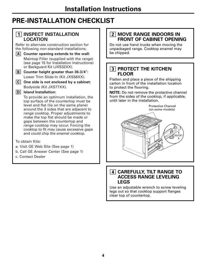
INSPECT INSTALLATIONLOCATION
Refer to alternate construction section forthe following non-standard installations.
Counter opening extends to the wall:
Maintop Filler (supplied with the range)(see page 15 for Installation Instructions)or Backguard Kit (JXS32XX).Counter height greater than 36-3/4″:
Lower Trim Slide-In (Kit JXS56XX).One side is not enclosed by a cabinet:
Bodyside (Kit JXS77XX).Island Installation:
To provide an optimum installation, thetop surface of the countertop must belevel and flat (lie on the same plane)around the 3 sides that are adjacent torange cooktop. Proper adjustments tomake the top flat should be made orgaps between the countertop andrange cooktop may occur. Forcing thecooktop to fit may cause excessive gapsand could chip the enamel cooktop.
To obtain Kits: a. Visit GE Web Site (See page 1)b. Call GE Answer Center (See page 1)c. Contact Dealer
D
C
B
A
1
4
Installation Instructions
PRE-INSTALLATION CHECKLIST
MOVE RANGE INDOORS INFRONT OF CABINET OPENING
Do not use hand trucks when moving theunpackaged range. Cooktop enamel may be chipped.
2
PROTECT THE KITCHENFLOOR
Flatten and place a piece of the shippingcarton in front of the installation location to protect the flooring.NOTE: Do not remove the protective channelfrom the sides of the cooktop, if applicable,until later in the installation.
3
CAREFULLY, TILT RANGE TOACCESS RANGE LEVELINGLEGS
Use an adjustable wrench to screw levelinglegs out so that cooktop support flangesclear top of countertop.
4
Protective Channel(on some models)
ADJUST

REMOVE THE DOOR IFNECESSARY
Door removal is not a requirement forinstallation of the product, but is an addedconvenience. To remove the door:
UNLOCK HINGES
Push both hinge locks down toward thedoor frame, to the unlocked position. Thismay require a flat blade screwdriver.
POSITION DOOR
Place hands on both sides of the door, andclose the oven door to the removal position. This is half way between the broil stop andfully closed.
B
A
5
5
Installation Instructions
Hingeslot
Hingeunlockedposition
Hingearm
REMOVE THE DOOR IFNECESSARY (cont.)
LIFT OFF DOOR
Lift door up and out until the hinge armsclear the slots.DO NOT LIFT THE DOOR BY THE HANDLE.
NOTE: The oven door is very heavy. Be sureyou have a firm grip before lifting the ovendoor off the hinges. Use caution once thedoor is removed. Do not lay the door on itshandle. This could cause dents or scratches.
C
5
Hinge clears slot
REMOVE PACKINGMATERIALS
Also remove labels on door, plastic on trimand panel and all tape around the range.
6
REMOVE STORAGE DRAWER
Pull the drawer out until it stops.
Lift the front of the drawer until thestops clear the guides.
Pull forward and remove the drawer.C
B
A
7
Rail
Guide
StopStop

6
Installation Instructions
PRE-INSTALLATION CHECKLIST (CONT.)
PRE-INSTALLATION CUTOUT AND REQUIRED CLEARANCESIf cabinets are placed less than 30″ above the range, see Alternate Construction, Step 19F, on page 16.
NOTE: Product meets ANSI Z21.1 requirements for 0″clearance to back and side walls below the cooktop.
Wall coverings, counters and cabinets around range mustwithstand heat (up to 194°F) generated by the range.
8
STANDARD INSTALLATION
If the construction of your cabinet cannot provide a 1/4″ flat area at the back of the countertop opening,consider changing the countertop to accommodate this dimension. See Alternate Construction section.
9
1/4″ min.flat
9/16″min.flat
29-15/16″–30-1/16″smooth cut
23-3/16″25″
typically
Wall
Flat areaR
1/4″9/16″min.flat
36″
29-15/16” min.30-1/16” max.
Acceptablegas line andelectricaloutlet area
35-7/8”–38” fromfloor to countertop
For optimuminstallation thesesurfaces must beflat and level
Follow instructionspackaged withalternate appliance
30” min. fromcooking surfaceto bottom ofoverheadcabinets
18” min. vertical distancefrom the bottom of theadjacent overhead cabinets
Countertop depth25” (typical)
1-1/4” min. countertopto top of drawer
6” min. from walls
23-3/16”
24” min.
30” min.
13” max.depth
2-1/2”
25”
2-1/2”7-1/2”
Max. depth of cord, plug,recept. box &gas hookup 4” to preventinterference with drawer
1-13/16″*
*NOTE: A 1-1/2″ minimum space must be maintained between the rear edge of the cooktop and the rear wall above the cooktop.

7
Installation Instructions
ELECTRICAL CONNECTIONS
INSTALLATION—ELECTRICALCONNECTIONSBecause of potential safety hazardsunder certain conditions, we stronglyrecommend against the use of anextension cord. However, if you stillelect to use an extension cord, it isabsolutely necessary that it is a ULlisted 3-wire grounding-type applianceextension cord and that the currentcarrying rating of the cord in amperesis equivalent to or greater than thebranch circuit rating. Such extensioncords are obtainable through your localappliance dealer.
IMPORTANT: (Please read carefully)FOR PERSONAL SAFETY, THISAPPLIANCE MUST BE PROPERLYGROUNDED.
An adequate electrical supply andoutlet must be used to operate theelectrical parts of your range.
• The power cord of this appliance isequipped with a three-prong (grounding)plug which must be used with a properlygrounded three-hole outlet with standard120 Volt, 60 cycle AC household current.
• When a standard two-prong wall receptacle is encountered, it is the personal responsibility and obligation of the customer to have it replaced with a properly grounded three-prong wall receptacle by a qualified electrician.
Do not under any circumstances cut orremove grounding prong from the rangecord. Failure to provide proper ground may create a hazardous condition.
B
A
10

MAKING THE CONNECTIONS(cont.)Install 1/2″ flare union adaptor to the 1/2″NPT elbow on pressure regulator.Connect flexible appliance connector toflare union.Move range into approximate positionand connect flexible connector to gassupply line with proper flare unionadaptor.
To prevent gas leaks, put a pipe jointsealant or Teflon® tape on all malethreads. NOTE: Make sure sealant or tapeis compatible with Natural and LP gases.When you are finished makingconnections, be sure that all range knobsare turned to OFF before you open themain gas supply valve.
WARNING: Do not use a flame to check for gas leaks. Use liquid leak detectorat all joints and connections to check for leaksin the system.
J
I
H
G
F
11
8
Installation Instructions
GAS CONNECTIONS
MAKING THE CONNECTIONS
Install a manual shut-off valve in the gassupply line in an easily accessible location.Know how and where to shut off the gassupply to the range.Shut off gas supply before removing anold range. Leave it off until hookup ofnew range is finished.Because solid pipe restricts moving therange, we recommend use of a C.S.A.certified flexible metal applianceconnector.
WARNING: Never reuse oldflexible connectors. The use of old flexibleconnectors can cause gas leaks and personalinjury. Always use new flexible connectorswhen installing a gas appliance.
Before making gas connections, makesure that the oven shut-off lever (visible atthe back of range) is in the open position.
E
D
C
B
A
11
3″
15″12″
31⁄2″
7″
Gas Inlet
Gas supply totop burners
Pressureregulator asseen fromfront of range
Gassupplyto oven
Oven shut-offlever shown inthe open position
Pressureregulator
Gassupplyline
90° streetelbow
Shut-off valve Flexible gas line
7″ Max.
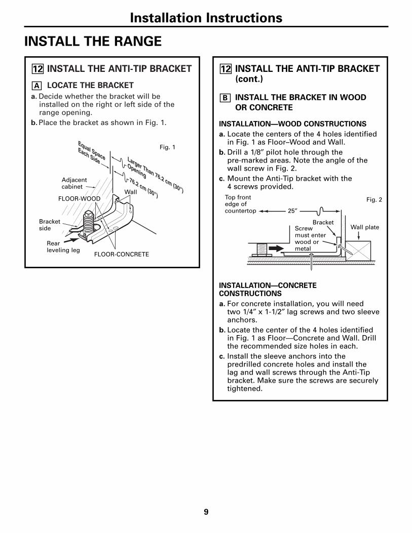
INSTALL THE ANTI-TIP BRACKET
LOCATE THE BRACKET
a. Decide whether the bracket will be installed on the right or left side of therange opening.
b. Place the bracket as shown in Fig. 1.
A
12
Rearleveling leg
Wall
FLOOR-CONCRETE
9
Installation Instructions
INSTALL THE RANGE
INSTALL THE ANTI-TIP BRACKET(cont.)
INSTALL THE BRACKET IN WOOD
OR CONCRETE
INSTALLATION—WOOD CONSTRUCTIONS
a. Locate the centers of the 4 holes identifiedin Fig. 1 as Floor–Wood and Wall.
b. Drill a 1/8″ pilot hole through the pre-marked areas. Note the angle of thewall screw in Fig. 2.
c. Mount the Anti-Tip bracket with the 4 screws provided.
INSTALLATION—CONCRETECONSTRUCTIONS
a. For concrete installation, you will need two 1/4″ x 1-1/2″ lag screws and two sleeveanchors.
b. Locate the center of the 4 holes identifiedin Fig. 1 as Floor—Concrete and Wall. Drillthe recommended size holes in each.
c. Install the sleeve anchors into thepredrilled concrete holes and install the lag and wall screws through the Anti-Tipbracket. Make sure the screws are securelytightened.
B
12
FLOOR-WOOD
Bracketside
Adjacentcabinet
Top frontedge ofcountertop 25″
Wall plateScrewmust enterwood ormetal
Bracket
Fig. 1
Fig. 2

SLIDE RANGE INTO OPENING
Position the range in front of the cabinetopening.Make sure that the cooktop edges thatoverhang the countertop clear thecountertop. If necessary, raise the unit by lowering the leveling legs.Push while lifting the range into theopening, until the range is within 2″of engaging the anti-tip bracket.Remove the protective trim from the sideof the cooktop (if provided).Using the adjustable pliers or wrench,carefully screw in the back leveling leguntil the cooktop overhang comes to rest on the countertop.
Carefully screw in the front two levelinglegs (similar to Step E) until the cooktopoverhang touches the countertop.Carefully push the range into the openinguntil the anti-tip bracket engages and thevertical sides are flush with the cabinet.
G
F
E
D
C
B
A
13
10
Installation Instructions
INSTALL THE RANGE (CONT.)
SLIDE RANGE INTO OPENING(cont.)Plug the range cord into the receptacle.Locate the cord in the back of the range in a manner that it will not touch or bemoved by the drawer.
H
13
STORAGE DRAWER
Position range cordso that there is nointerference withstorage drawer
Adjustablewrench or pliers
Countertop
FINAL CHECK OF ANTI-TIPBRACKET
When installation is complete and the range isin place, check to be sure that the rear levelingleg is fully inserted into the slot of the Anti-TipBracket.
14
Cabinet
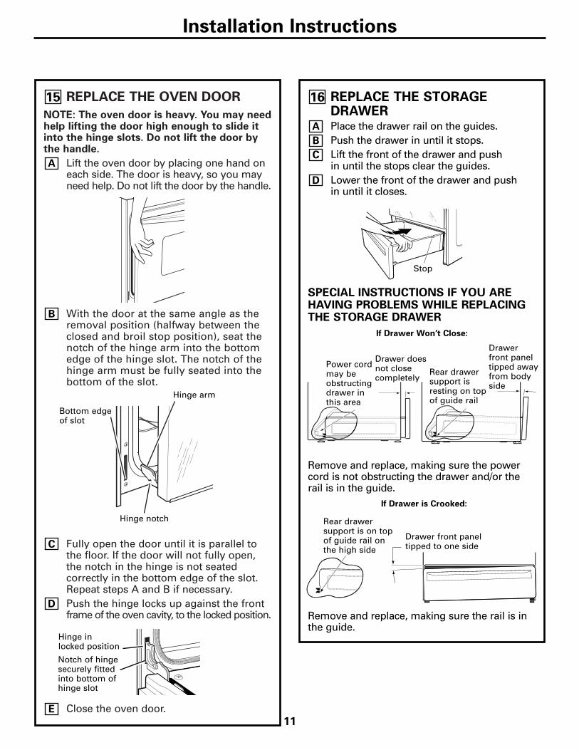
REPLACE THE OVEN DOOR
NOTE: The oven door is heavy. You may needhelp lifting the door high enough to slide itinto the hinge slots. Do not lift the door bythe handle.
Lift the oven door by placing one hand oneach side. The door is heavy, so you mayneed help. Do not lift the door by the handle.
With the door at the same angle as theremoval position (halfway between theclosed and broil stop position), seat thenotch of the hinge arm into the bottomedge of the hinge slot. The notch of thehinge arm must be fully seated into thebottom of the slot.
Fully open the door until it is parallel tothe floor. If the door will not fully open,the notch in the hinge is not seatedcorrectly in the bottom edge of the slot.Repeat steps A and B if necessary.Push the hinge locks up against the frontframe of the oven cavity, to the locked position.
Close the oven door.E
D
C
B
A
15
Installation Instructions
REPLACE THE STORAGEDRAWERPlace the drawer rail on the guides. Push the drawer in until it stops. Lift the front of the drawer and push in until the stops clear the guides. Lower the front of the drawer and push in until it closes.
SPECIAL INSTRUCTIONS IF YOU AREHAVING PROBLEMS WHILE REPLACINGTHE STORAGE DRAWER
Remove and replace, making sure the powercord is not obstructing the drawer and/or therail is in the guide.
Remove and replace, making sure the rail is inthe guide.
D
C
B
A
16
Stop
Bottom edgeof slot
Hinge in locked position
Notch of hingesecurely fittedinto bottom ofhinge slot
Drawer doesnot closecompletely
Drawerfront paneltipped awayfrom bodyside
Rear drawersupport is on top of guide rail on the high side
Drawer front paneltipped to one side
Hinge arm
Hinge notch
If Drawer Won’t Close:
If Drawer is Crooked:
Power cordmay beobstructingdrawer inthis area
Rear drawersupport isresting on topof guide rail
11
12
Installation Instructions
INSTALL THE RANGE (CONT.)
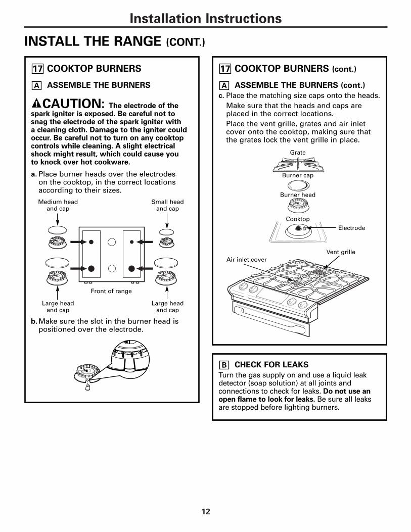
COOKTOP BURNERS
ASSEMBLE THE BURNERS
CAUTION: The electrode of thespark igniter is exposed. Be careful not tosnag the electrode of the spark igniter with a cleaning cloth. Damage to the igniter couldoccur. Be careful not to turn on any cooktopcontrols while cleaning. A slight electricalshock might result, which could cause you to knock over hot cookware.
a. Place burner heads over the electrodes on the cooktop, in the correct locationsaccording to their sizes.
b.Make sure the slot in the burner head ispositioned over the electrode.
A
17
CHECK FOR LEAKS
Turn the gas supply on and use a liquid leakdetector (soap solution) at all joints andconnections to check for leaks. Do not use anopen flame to look for leaks. Be sure all leaksare stopped before lighting burners.
B
Medium head and cap
Large head and cap
Small head and cap
Large head and cap
COOKTOP BURNERS (cont.)
ASSEMBLE THE BURNERS (cont.)
c. Place the matching size caps onto the heads.Make sure that the heads and caps areplaced in the correct locations.Place the vent grille, grates and air inletcover onto the cooktop, making sure thatthe grates lock the vent grille in place.
A
17
Grate
Burner cap
Burner head
CooktopElectrode
Vent grilleAir inlet cover
Front of range
Installation Instructions
PRESSURE TEST INFORMATION
The maximum allowable supply pressure forthe regulator is 14″ W.C. The minimum supplypressure needed to check the regulator settingis 7″ W.C. for natural gas and 10″ W.C. for LP gas.
WARNING: The range and itsindividual shut-off valve must be disconnectedfrom the gas supply piping system during anypressure testing of the gas supply system attest pressures of more than 1/2 psig (poundsper square inch gauge). The range must beisolated from the gas supply piping system byclosing its individual shut-off valve during anypressure testing of the gas supply system attest pressures equal to or greater than 1/2psig. NOTE: 1/2 psig = 13.855″ w.c.
C
CHECK THE IGNITERS
Operation of the electric igniters should bechecked after the cooktop and supply line have been carefully checked for leaks and thecooktop has been connected to the electricalpower.
a. Turn on gas.b. Push and turn a burner valve to the LITE
position.• The burner valve should light when gas
is available to the burner.• Once the burner lights, it should be
turned out of the LITE position.c. Try each valve separately until all burners
have been checked.
D
BURNER IGNITION
Cooktop Spark Ignition—When you turn the cooktop knob to LITE, the spark ignitermakes a series of electric sparks (tickingsounds) which light the burner. During apower failure the burners will not lightautomatically. In an emergency, a cooktopburner may be lit with a match by followingthe steps below.
WARNING: Lighting gas burnerswith a match is dangerous. You should matchlight the cooktop burners only in anemergency.
a. Light a match and hold the flame near theburner you want to light. Wooden matcheswork best.
b. Push in and turn the control knob slowly.Be sure you are turning the correct knobfor the burner you are lighting.
NOTE: If the burner does not light withinfive seconds, turn the knob off and wait fiveminutes before trying again.
E
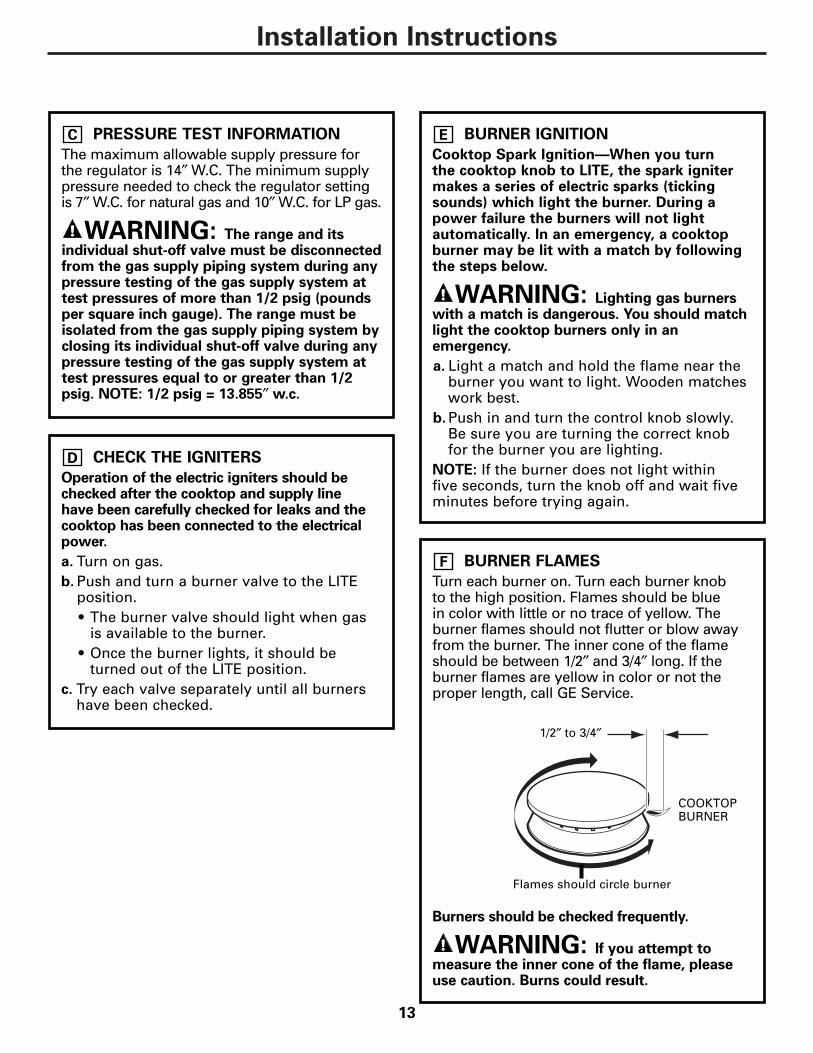
BURNER FLAMES
Turn each burner on. Turn each burner knob to the high position. Flames should be blue in color with little or no trace of yellow. Theburner flames should not flutter or blow awayfrom the burner. The inner cone of the flameshould be between 1/2″ and 3/4″ long. If theburner flames are yellow in color or not theproper length, call GE Service.
Burners should be checked frequently.
WARNING: If you attempt tomeasure the inner cone of the flame, pleaseuse caution. Burns could result.
F
1/2″ to 3/4″
COOKTOPBURNER
Flames should circle burner
13

14
Installation Instructions
INSTALL THE RANGE (CONT.)
BAKE AND BROIL BURNERS
If the bake and/or broil burners have lifting or“lazy” (floating) flames or you have a yellowflame, perform the following procedures:
CHECKING THE OVEN BURNERS
To check the bake burner flames with theoven door in the closed position:
1. Open the door and remove it.2. Remove the oven racks.3. Remove the oven bottom.
Lift the oven bottom up at rear and pullforward.
4. Remove the four screws holding the burnerbaffle (flame spreader) to the burner box.
5. Install and close the oven door.6. Turn on the bake burner.
As you watch the flames, check thefollowing:
• Burner flames should not flutter or blowaway from the burner.
• They should be blue in color with no traceof yellow.
The broil burner flames may be seen withoutremoving the racks, oven bottom or bakebaffles.
A
18 ADJUST THE AIR SHUTTER
BAKE BURNER
1. Remove the orifice fitting cover.2. Use a screwdriver to loosen the air shutter
screw.3. Adjust the air shutter to 11/32″.4. Retighten the air shutter screw.
WHAT ADJUSTMENT TO MAKE:
a. If the flames are yellow, open the airshutter more than the original setting.
b. If the flames blow away or fluttered fromthe burner, close the air shutter more thanthe original setting.
Burners should be checked frequently.
BROIL BURNER
1. The broil burner is located and accessiblein the top rear of the oven.
2. Using ascrewdriver,loosen the airshutteradjustment screw.
3. Make the airshutteradjustment.
4. Retighten the airshutter screw.
5. Check the innercone of the flame.It should bebetween 1/2″ and3/4″ long for theoven bake andbroil burners.
WHEN ALL ADJUSTMENTS ARE MADE ANDTHE RESULTS ARE SATISFACTORY
1. Replace the orifice fitting cover.2. Replace the burner baffle (flame spreader)
and screws.3. Replace the oven bottom.4. Replace the oven door.
B
Air Shutter Adjustment Screw
Dim. “A”
1/2" TO 3/4"
CONO INTERIOR DE LLAMA
QUEMADOR PARAHORNEAR/ASAR
Inner cone offlame
Oven broilerburner
1/2″ to 3/4″
Air shutteradjustment screw
Dim. “A”
Orifice fittingcover
Air shutterAir shutterscrew

15
Installation Instructions
ALTERNATE CONSTRUCTIONPREPARATION
OPTIONAL MAINTOP FILLER ORBACKGUARD KIT
If counter opening extends to the wall, it willrequire Maintop Filler Kit (supplied with therange) or Backguard Kit (JXS32XX) to closethe gap.NOTE: If the countertop is greater than 25″, it will show a gap between the backguard and wall or between filler kit and the wall.If the countertop is less than 25″, a gap willoccur between the countertop front and thecontrol panel ends (see Step 13G).If you are using the optional backguard kit,refer to the backguard kit instructions forinstallation details.
If you use the filler kit, place the metal fillerpiece supplied with the range to the back of the range as shown in the figure below.Start the 2 screws into the upper holes at theoutside rear of the range above the louversand through the slots in the trim, holding the filler piece centered on the maintop frame and pushing upward to close the gapbetween the bottom of the cooktop and the filler trim.
A
19 When the trim is set in the proper position,tighten the 2 mounting screws. The top of the trim should be located below the cooktopedge to prevent pots, pans and skillets fromdamaging the painted parts.Refer to the Standard Installation of theRange on page 6.
Wall
25″Must belevel
Must beflat
30″ smooth cut
Must be level31-1/8″
Mustbeflat
(2) #8screws
Maintop filler
Range
Cooktop
FOR NON-BUILT-IN INSTALLATION(END OF CABINET LOCATION)
When installing the range at the end of a cabinet section which will expose theunfinished side of the range, use Body SideKit (JXS77XX). Refer to the kit instructions forinstallation details.
B
ISLAND INSTALLATION
Attach the Anti-Tip bracket per instructions in Step12, making sure that the rear of the bracket is 25″from the front of the countertop.Be aware that the screws provided are long andmay penetrate through the back of the islandcabinets. In this event, use shorter screws (notprovided) or the screws provided should be usedin the floor (see Step 12B for Wood/Concrete FloorInstallation). Do not use Backguard Kit JXS32XX.
C

Installation Instructions
INSTALL THE RANGE (CONT.)
ALTERNATE CONSTRUCTIONPREPARATION (cont.)
FOR CABINET OPENINGSAPPROXIMATELY 30-3/8″
If range is installed in cabinet openingapproximately 30-3/8″, the Vertical Side Trim Kit(JXS86XX) should be used to cover gaps betweenrange sides and cabinet. Refer to the kitinstructions for installation details.
D
19
CABINETS OVER THE RANGE LESSTHAN 30″
If a 30″ clearance between cooking surface andoverhead combustible material or metal cabinetscannot be maintained, protect the underside of thecabinets above the cooktop with not less than 1/4″insulating millboard covered with sheet metal notless than 0.0122″ thick.
E
OPERATION CHECKLIST• Double check to make sure everything in
this guide has been completed. Recheckingsteps will ensure safe use of the cooktop.
• Make sure all controls are left in the OFFposition.
• Make sure the flow of combustion andventilation air to the cooktop is unobstructed.
• The serial plate for your Range is located under the oven door above the storagearea. In addition to the model and serialnumbers, it tells you the ratings of theburners and the type of fuel and pressurethe cooktop was adjusted for when it leftthe factory.
• When ordering parts, always include theserial number and model number to ensureproper replacement parts.
• Recheck Steps: Double check to make sureeverything in this guide has been completed.Rechecking steps will ensure safe use ofthe Range.
20
IN SOME CASESWith L.P. gas, some yellow tipping on the outer cone is normal.Foreign particles in the gas line maycause an orange flame at first, but thiswill soon disappear.
SPECIAL NOTE:
To convert the oven back to natural gas,reverse the instructions given in making L.P. Adjustments.
Once the conversion is completeand checked ok, fill out the LPsticker and include your name,organization and the date the
conversion was made. Apply the sticker nearthe regulator to alert others in the future thatthis appliance has been converted to LP gas.If converting back to natural gas from LP,please remove the sticker so others know theappliance is set to use natural gas.
B
A
Please see L.P. conversion instructionssupplied with this range when L.P. Gas is used.
NOTE: Instructions are mounted onregulator bracket.
ADJUSTING LOW FLAME SETTINGON COOKTOP BURNERSLow setting adjustments must be made withtwo other burners in operation on a mediumsetting. This procedure prevents the lowflame from being set too low, resulting in theflame being extinguished when other burnersare turned on.
Remove the valve control knobs.Through the opening, locate the valvebypass screw located on the lower rightside of the valves.Using a small screwdriver, screw downthe bypass screw fully in a clockwiserotation.
C
B
A
16 Printed in the United States