installation guide cv60 dc-dc converterepsfiles.intermec.com/eps_files/eps_man/962-054-107.pdfii...
TRANSCRIPT

CV60 DC-DCConverter
Installation Guide

ii CV60 DC-DC Converter Installation Guide
Intermec Technologies CorporationWorldwide Headquarters Technical Communications 6001 36th Ave.W. 550 Second Street SE Everett, WA 98203 Cedar Rapids, IA 52401 U.S.A. U.S.A.www.intermec.comThe information contained herein is provided solely for the purpose of allowing customers to operate and service Intermec-manufactured equipment and is not to be released, reproduced, or used for any other purpose without written permission of Intermec Technologies Corpora-tion.Information and specifications contained in this document are subject to change without prior notice and do not represent a commitment on the part of Intermec Technologies Corporation.© 2003-2006 by Intermec Technologies Corporation. All rights reserved. The word Intermec, the Intermec logo, Norand, ArciTech, Beverage Routebook, CrossBar, dcBrowser, Duratherm, EasyADC, EasyCoder, EasySet, Fingerprint, i-gistics, INCA (under license), Intellitag, Intell-itag Gen2, JANUS, LabelShop, MobileLAN, Picolink, Ready-to-Work, RoutePower, Sabre, ScanPlus, ShopScan, Smart Mobile Computing, TE 2000, Trakker Antares, and Vista Powered are either trademarks or registered trademarks of Intermec Technologies Corporation.There are U.S. and foreign patents as well as U.S. and foreign patent applications pending.

Contents
ContentsBefore You Begin . . . . . . . . . . . . . . . . . . . . . . . . . . v
Safety Information. . . . . . . . . . . . . . . . . . vGlobal Services and Support . . . . . . . . . . vWho Should Read this Guide . . . . . . . . vii
1 Introduction . . . . . . . . . . . . . . . . . . . . . . . . . . . . . . . . . . 1Installation Guidelines . . . . . . . . . . . . . . . . . . . . . . 2
About the CV60 DC Power Supply Kit. . 2Considerations. . . . . . . . . . . . . . . . . . . . . 2
Input Power Cable . . . . . . . . . . 3Inline Fuse . . . . . . . . . . . . . . . . 3Output Power Cable . . . . . . . . . 4
Configuration Chart . . . . . . . . . . . . . . . . 5New Installation. . . . . . . . . . . . . . . . . . . . . . . . . . . 6
2 Installation Procedures. . . . . . . . . . . . . . . . . . . . . 7About this Installation . . . . . . . . . . . . . . . . . . . . . . 8Installation Summary . . . . . . . . . . . . . . . . . . . . . . . 9Tools Required . . . . . . . . . . . . . . . . . . . . . . . . . . . 9Before You Start. . . . . . . . . . . . . . . . . . . . . . . . . . 10Connect Power Input Cable. . . . . . . . . . . . . . . . . 10Mount the Power Supply . . . . . . . . . . . . . . . . . . . 11Power Cable Installation . . . . . . . . . . . . . . . . . . . 12Power Cable Connections . . . . . . . . . . . . . . . . . . 12Cable Termination. . . . . . . . . . . . . . . . . . . . . . . . 13Cut and Strip Power Cable . . . . . . . . . . . . . . . . . 14Heat Shrink Tubing. . . . . . . . . . . . . . . . . . . . . . . 15Prepare the Cable Ends . . . . . . . . . . . . . . . . . . . . 16Power Source Connections. . . . . . . . . . . . . . . . . . 16Direct Battery Connections . . . . . . . . . . . . . . . . . 17
Side-Mount Battery Terminals . . . . . . . 17Top-Mount Battery Terminals . . . . . . . 19
Cable Clamps. . . . . . . . . . . . . . . . . . . . . . . . . . . . 20Final Connections . . . . . . . . . . . . . . . . . . . . . . . . 20
CV60 DC-DC Converter Installation Guide iii
Contents
3 Troubleshooting Information . . . . . . . . . . . .21Procedures . . . . . . . . . . . . . . . . . . . . . . . . . . . . . .22
Inspection . . . . . . . . . . . . . . . . . . . . . . .22Power Supply. . . . . . . . . . . . . .22Cables, Connections . . . . . . . .22Fuse . . . . . . . . . . . . . . . . . . . . .22
Electrical Measurements. . . . . . . . . . . . .23Voltage . . . . . . . . . . . . . . . . . .23Continuity. . . . . . . . . . . . . . . .23
Substitution . . . . . . . . . . . . . . . . . . . . . .23Advantages. . . . . . . . . . . . . . . .23Disadvantages . . . . . . . . . . . . .23When to Substitute . . . . . . . . .23
Troubleshooting Charts . . . . . . . . . . . . . . . . . . . .24Power Supply Reset . . . . . . . . . . . . . . . .24Power Supply Pinouts . . . . . . . . . . . . . .25
iv CV60 DC-DC Converter Installation Guide

Before You BeginThis section provides you with safety information, technical sup-port information, and sources for additional product informa-tion.
Safety InformationYour safety is extremely important. Read and follow all warnings and cautions in this document before handling and operating Intermec equipment.You can be seriously injured, and equip-ment and data can be damaged if you do not follow the safety warnings and cautions.This section explains how to identify and understand warnings, cautions, and notes that are in this document.
A warning alerts you of an operating procedure, practice, condition, or statement that must be strictly observed to avoid death or serious injury to the persons working on the equipment.
A caution alerts you to an operating procedure, practice, condition, or statement that must be strictly observed to prevent equipment damage or destruction, or corruption or loss of data.
.
Note: Notes either provide extra information about a topic or contain special instructions for handling a par-ticular condition or set of circumstances.
Global Services and SupportWarranty Information
To understand the warranty for your Intermec product, visit the Intermec web site at www.intermec.com and click Service & Support. The Intermec Global Sales & Service page appears. From the Service & Support menu, move your pointer over Sup-port, and then click Warranty.Disclaimer of warranties: The sample code included in this docu-ment is presented for reference only. The code does not necessar-ily represent complete, tested programs. The code is provided “as is with all faults.” All warranties are expressly disclaimed, includ-ing the implied warranties of merchantability and fitness for a particular purpose.
CV60 DC-DC Converter Installation Guide v

Web SupportVisit the Intermec web site at www.intermec.com to download our current manuals (in PDF). To order printed versions of the Intermec manuals, contact your local Intermec representative.To download a PDF manual
1 Visit the Intermec web site at www.intermec.com.
2 Click Service & Support > Manuals.
3 In the Select a Product field, choose the product whose docu-mentation you want to download.
Visit the Intermec technical knowledge base (Knowledge Cen-tral) at intermec.custhelp.com to review technical information or to request technical support for your Intermec product.
Telephone SupportThese services are available from Intermec Technologies.
Service Description
In the U.S.A. and Canada call 1-800-755-5505 and choose this option
Order Intermec products
• Place an order.
• Ask about an existing order.
1 and then choose 2
Order Intermec media
Order printer labels and rib-bons.
1 and then choose 1
Order spare parts Order spare parts.
1 or 2 and then choose 4
Technical Support Talk to technical support about your Intermec product.
2 and then choose 2
vi CV60 DC-DC Converter Installation Guide

Outside the U.S.A. and Canada, contact your local Intermec rep-resentative. To search for your local representative, from the Intermec web site, click Contact.
Who Should Read this GuideThis guide is written for the person who is responsible for install-ing, configuring, and maintaining the dc-dc converter. This guide provides you with information about the features of the dc-dc converter, and how to install, configure, operate, maintain, and troubleshoot it.Before you work with the vehicle power supply, you should be a trained service person or one familiar with forklift truck service and maintenance.
Service • Get a return authorization number for authorized service center repair.
• Request an on-site repair technician.
2 and then choose 1
Service contracts • Ask about an existing con-tract.
• Renew a con-tract.
• Inquire about repair billing or other ser-vice invoic-ing questions.
1 or 2 and then choose 3
Service Description
In the U.S.A. and Canada call 1-800-755-5505 and choose this option
CV60 DC-DC Converter Installation Guide vii

viii CV60 DC-DC Converter Installation Guide

1CV60 DC-DC Converter Installation Guide
1Introduction
This chapter describes installation practices andunique components in the kits.

1 IntroductionChapter —
2 CV60 DC-DC Converter Installation Guide
Installation GuidelinesThe installer should be familiar with the brands and models ofequipment where this kit is installed. They should also be trainedand experienced in vehicle electrical systems.Installer must follow these guidelines and the installation proceduresas well as those of the lift manufacturer to ensure a safe and reliableinstallation.
About the CV60 DC Power Supply KitThe CV60 DC power supply kits includes these items:S Power supplyS Power supply input cable, 2.44 m (8 ft)S Fused power cable, 46 cm (18 in)S #10 terminal ringS 3AB, 20A/250V fuses (2)S Insulated quick-connect tabs (2)S M2A-F1800-00
The power supply provides 12 VDC output that is filtered andregulated. It also provides over-current, over-voltage, over-tem-perature, and shorted-output protection.
ConsiderationsNote: This document assumes that you have alreadyinstalled the CV60 on your vehicle and that you havethe correct power supply and power supply inputcable for your vehicle before you proceed with theinstallation.
The power supply shall be mounted to the vehicle chassis, or con-nected (electrically) via external wire to the vehicle chassis. Chassisground to the computer or other equipment is then established viathe power supply output cable.Since the power supply will produce heat, it is advisable to mount iton a minimum of 130-160 square inches (approximately one squarefoot or more) of metallic surface. This location should not be in thevicinity of sources of vehicle-generated heat. Use the hardware suppliedin the kit to mount the power supply, do not use sheet metal screws or oth-er less permanent or rugged mounting solutions.

1 Introduction—Chapter
3CV60 DC-DC Converter Installation Guide
A pair of green light-emitting diodes (LED), located near theoutput connectors on the power supply, will be lit whenevervoltage is supplied to the output power cables.
One LED indicates main power is OK (3 pin connector). The sec-ondary power LED will indicate Heater Power (2-pin connector) isOK.
Note: If the secondary LED is not lit when usingboth main and secondary power outputs, input pow-er to the DC-DC converter is probably less than9-10 volts.
Green LEDs(power output indicators)
Output Connector(secondary power)
P/N 851-070-003 6-60V, 14A
Input Connector
Output Connector(main power)
Input Power CableNote: The input power cable may be shortened as need-ed. It should NOT be extended on 12V or lower systems.On higher voltage systems, extensions should be kept to aminimum and should be of equivalent or higher gaugewire. Keep the cable as short as possible. Extra cable picksup noise, adds power loss and is prone to snagging onequipment.
The input power cable is approximately 9 feet long. One end hasa 4-pin connector, the other has a 2-pin connector. Cut off the2-pin connector and terminate it for connection to the vehicle powersource.
Inline FuseA snap-twist inline fuse holder is furnished as part of this kit. Itmust be connected as close as possible (electrically and physically)to the vehicle power source. It provides catastrophic failure,short-circuit protection for the entire input power cable and the

1 IntroductionChapter —
4 CV60 DC-DC Converter Installation Guide
power supply input. The fuse holder contains a 3AB, 20 ampere250 Vdc fuse. Should it fail, diagnose the problem and correct it,then replace with exactly the same size and type fuse.
The fuse is sized for a 12 volt system with heater. In systems thatrun at higher voltages, a smaller amperage fuse may be used.
See the fuse chart below for fuse ratings for non-heater CV60installations.
Fuse Chart
Voltage Fuse Rating
24V 10A
48V 5A
96V 5A
Output Power CableNote: Ensure that you have the correct CV60 powercable for your type of location.
Output power cables are approximately 6 feet long and have a du-rable 3-pin connector, and 2-pin connector to mate with the powersupply. The connector on the far end of the cable is specific to thecomputer. These connectors have heavy duty metal housings andenhanced strain relief to provide added reliability in the mobile en-vironment.
Note: Connect both connectors to the power supplyeven for non-heated CV60s. This prevents accidentaldamage or dirt accumulation to the unused connector.

1 Introduction—Chapter
5CV60 DC-DC Converter Installation Guide
Configuration ChartUse the configuation chart on the following pages as a guide foryour vehicle installation.
Cable and Power Supply Chart
Truck Voltage Power Supply Output Cable Heater
12V-60V 851-070-003 M2AF1800-XX Yes/No
Use the chart below as a guide for your vehicle installation with theUPS (P/N: 851-059-002) and power supply.
UPS Cable and Power Supply Chart
DC-DC UPS Use Cable:
851-070-003 851-059-002 226-340-002 and 309-065-003 ferrite bead

1 IntroductionChapter —
6 CV60 DC-DC Converter Installation Guide
New Installation
Cable
P/N 226-340-00X
InputCable P/N
M2A-F1800-XX
Output
DC-DC Converter P/N 851-070-003
Material Description
203-669-001 Kit, CV60 PS
203-685-001 Installation Kit, Vehicle Power Supply
851-070-003 DC/DC Converter 6-60Vin/Dual 12Vout
M2A-F1800-XX Cable, 3-pin/2-pin to 5-pin Y-cable
589162-001 CNTNR CDB, 8.25 x 6.125 x 4.00
962-054-107 Installation Guide

7CV60 DC-DC Converter Installation Guide
2InstallationProcedures
This chapter outlines mechanical and electricalinstallation instructions.

2 Installation ProceduresChapter —
8 CV60 DC-DC Converter Installation Guide
About this InstallationFollow the instruction procedures as closely as possible whilekeeping the following in mind:
S Power supply must be securely mounted.
S Mounting surface must be sturdy.
S Mounting surface must be able to sink power supply heat.
S Fuse must be close to vehicle power source.
S Keep cables as short as possible, and secure them at least every18 inches (50 cm).
S Installation must not violate fork lift manufacturer’s require-ments and should be done by trained professionals.

2 Installation Procedures—Chapter
9CV60 DC-DC Converter Installation Guide
Installation SummaryInstallation consists of five primary steps, which should be carriedout in the following order:
1 Connect the input cable to the power supply.
2 Mechanically install and secure the power supply.
3 Route and secure the power cable.
4 Shorten cable as appropriate, then crimp the fuse holder to thejoined RED and BLACK wires (positive). Crimp a terminal ringto the joined WHITE and GREEN wires (negative). Insulate asintructed.
5 Make final connections to the vehicle power source.
Tools RequiredS Common hand tools (screwdriver, pliers, etc.)
S Heat gun for heat shrink tubing
S Wire crimping and stripping tool
S Electric drill, drill bits
2 Installation ProceduresChapter —
10 CV60 DC-DC Converter Installation Guide
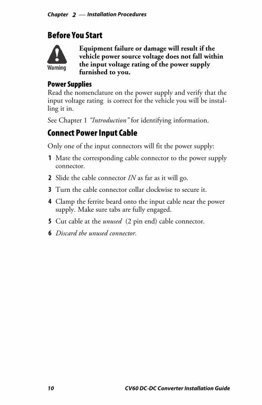
Before You StartEquipment failure or damage will result if thevehicle power source voltage does not fall withinthe input voltage rating of the power supplyfurnished to you.
Power SuppliesRead the nomenclature on the power supply and verify that theinput voltage rating is correct for the vehicle you will be instal-ling it in.
See Chapter 1 “Introduction” for identifying information.
Connect Power Input CableOnly one of the input connectors will fit the power supply:
1 Mate the corresponding cable connector to the power supplyconnector.
2 Slide the cable connector IN as far as it will go.
3 Turn the cable connector collar clockwise to secure it.
4 Clamp the ferrite beard onto the input cable near the powersupply. Make sure tabs are fully engaged.
5 Cut cable at the unused (2 pin end) cable connector.
6 Discard the unused connector.

2 Installation Procedures—Chapter
11CV60 DC-DC Converter Installation Guide
Mount the Power SupplyThe input power cable is approximately 9 feet long and can beshortened as needed. It must NOT be extended under any cir-cumstances. The output power cable is approximately 6 feet andcannot be lengthened.
Note: We do not recommend changing the length ofthe output power cable as it requires a splice connec-tion which is prone to failure or cause intermittentproblems.
You must take these lengths and the intended location of yourelectronic equipment into consideration when choosing a mount-ing location for the power supply.
The mounting surface location must provide 130-160 squareinches of metallic surface to sink heat generated by the powersupply. This metallic mounting surface must be connected tothe vehicle chassis electrically. In rare instances, you may have tofabricate a flexible wire or braid to bond the mounting surface tovehicle chassis ground. See page 2 “Considerations” for moreinformation.
Appropriate hardware is furnished in this installation kit formounting the power supply. Use mounting Method A in situa-tions where you can easily access the back side of the mountinglocation to install a lock nut and washer.Use Method B where the back side of the mounting location isinaccessible. Note that this method requires that the mountingplate be thick enough to accept and retain sufficient thread toprovide a secure and reliable mechanical installation.Method A:
1 Mark and center punch the two mounting holes locations.2 Use a 1/4-inch drill bit to make the two mounting holes.3 Use 1/4” hex bolts with flat washers and locking nuts to
install the power supply.Method B:
1 Mark and center punch the two mounting hole locations.2 Use a #7 drill bit to make the mounting holes.
3 Use a 1/4-20 tap to thread the mounting holes.

2 Installation ProceduresChapter —
12 CV60 DC-DC Converter Installation Guide
4 Place a lockwasher on each bolt.5 Insert the bolt/lockwasher assemblies through the power sup-
ply holes and into the threaded mounting holes.
Power Cable InstallationFollow these guidelines and other instructions closely wheninstalling power cables.Completely install power cables before making connections toequipment.Route the power cables from the general area where the powersupply will be mounted.Use a snap-in bushing (requires a 9/16” hole) if the power cablepasses through a firewall or other sheet metal.Make sure that cable routing does not interfere with otherequipment or vehicle controls.Make sure that cable routing does not invite damage to thecable.Secure the cables at least every 18 inches thoughout the cablerun: use adjustable clamps (see the last page in this chapter) orwire-tie to existing vehicle cable runs.
Warning: If this installation will be on agas-powered vehicle, you MUST install either anOn/Off switch (minimum 15A dc rating such asITW part number 163-900-034) or an automaticshut off device in series with the in-line fuse holder.Charge Guard, Inc. 400 Highland Avenue, Altoona,PA 16602 (814-941-4100) manufactures aCHARGE GUARDt device for this purpose.
Power Cable ConnectionsThe fuse holder from the input power cable must be connectedas close (physically and electrically) as possible to the positive sideof the vehicle power source. The remaining colored wires mustbe connected to the negative side of the vehicle power source. Inthis installation, the shield wire must be connected to the vehiclechassis.Instructions are not included for connecting to various possiblevehicle power sources. It is assumed that the trained professionalinstall is knowledgeable on the brands and models of vehicles he

2 Installation Procedures—Chapter
13CV60 DC-DC Converter Installation Guide
or she is working with. Both large (3/8 inch) and smaller termi-nal rings are provided to accomodate most installation needs.
This kit contains additional bolts, nuts, and washers in the eventyou will connect the input power cable directly to a vehicle bat-tery. The intended use for these parts is detailed in the instruc-tions that follow.
Cable TerminationYou must cut the cable to length, cut off a portion of the outercable jacket and strip the individual wire ends of the cable asinstructed. Heat shrink tubing is furnished in this kit and mustbe slipped onto the cable or wires before terminating them.
Then, you must install the fuse holder in series with the positivewires and install a terminal ring on the negative wires.
Finally, you must mechanically complete the connections to thevehicle power source or battery and electrically connect theshield wire to vehicle chassis ground using a self-tapping screwand flat washer.

2 Installation ProceduresChapter —
14 CV60 DC-DC Converter Installation Guide
Cut and Strip Power Cable1 Cut the power cable near the power source or battery.
2 Strip the cable jacket back 12-14 inches.
3 Slide heat shrink tubing over cable jacket.
4 Strip 1/4” of insulation from individual wires.
5 Twist the white and green (negative) wires together.
6 Twist the red and black (positive) wires together.
7 Twist the shield wire and slide the 1/8” heat shrink tubingonto it.
Note: See page 12 when installing on gas poweredvehicles.
Input
Power
Cable
Heatshrink Tubing
Green and White WIres (negative)
Red and Black WIres (positive)
Shield wire w/heatshrink applied
Strip the Cable Jacket 12-14 inches

2 Installation Procedures—Chapter
15CV60 DC-DC Converter Installation Guide
Heat Shrink TubingThis kit contains a 6-inch length of 3/8 inch heat shrink tubingwhich you will cut into three pieces, and a 12 inch length of 1/8inch heat shrink tubing for the shield wire. Tubing must be inplace before terminating wire ends. Crimp terminal rings andfuse holder ends, then position all heat shrink tubing in thelocations shown. Use a heat gun to shrink tubing.
3/8” 3/8” 3/8”
1/8”
Green and White twisted pair
Red and Black twistedpair
Shield wire
Heatshrink locations

2 Installation ProceduresChapter —
16 CV60 DC-DC Converter Installation Guide
Prepare the Cable EndsBoth large (3/8 inch) and smaller (#10) terminal rings are providedfor your selection and use in the following steps. A small (#10) ter-minal should be crimped to the shield wire and then fastened to ve-hicle chassis ground.
1 Crimp a terminal ring onto the white-green twisted pair (neg-ative) of wires.
2 Cut the red-black twisted pair (positive) of wires at the midpoint.Strip exposed ends.
3 Position short lengths of heat shrink tubing as indicated inillustration on page 18.
4 Crimp the fuse holder to the positive wires from the cable.
5 Shorten the remaining positive wires (pigtail) if desired andposition a short length of heat shrink tubing onto this pigtail.
6 Crimp this positive pigtail to the fuse holder.
7 Securely crimp a terminal ring to the end of the positive pigtailfrom the fuse holder.
8 Slide heat shrink over crimps, shrink with heat gun.
Power Source ConnectionsThe next few pages show you the intended purpose of nuts.bolts, and washers that are included in this kit if you will beconnecting the power cable directly to a vehicle battery.
Additional hardware is not provided in this kit for connectingthe power cable to other vehicle power sources. Refer to themanufacturer’s technical manual for the vehicle if necessary.

2 Installation Procedures—Chapter
17CV60 DC-DC Converter Installation Guide
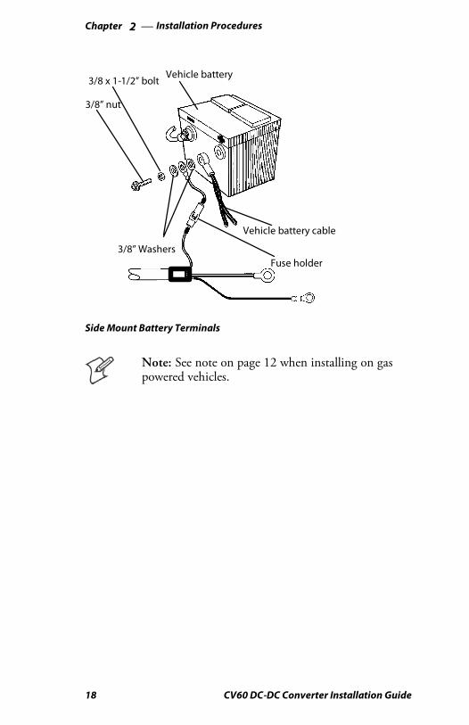
Direct Battery ConnectionsSide-Mount Battery Terminals1 Remove both terminal screws from the vehicle battery.
2 Screw a 3/8” nut as far as it will go onto a 3/8” x 1-1/2” boltfurnished in the kit.
3 Slip a 3/8” washer onto the bolt.
4 Slide the positive (fuse holder red wire) terminal ring onto thepositive battery bolt.
5 Slip a second 3/8” washer onto that bolt.
6 Slide the vehicle positive battery cable onto the bolt.
7 Thread the bolt assembly (steps 1-6, above) into the positive batteryterminal. Tighten the bolt until it bottoms out, but do not over-tighten the bolt.
8 Tighten the nut securely against the washers and cables.
9 Use a self-tapping screw and flat washer to connect shield wire tovehicle chassis ground.
Repeat steps 2 through 8 for the negative wire (white-greenpair) from the input power cable, connecting the wire to thenegative (-) battery terminal.
Note: See note on page 12 when installing on gaspowered vehicles.
2 Installation ProceduresChapter —
18 CV60 DC-DC Converter Installation Guide
3/8” nut
3/8 x 1-1/2” boltVehicle battery
Vehicle battery cable
Fuse holder3/8” Washers
Side Mount Battery Terminals
Note: See note on page 12 when installing on gaspowered vehicles.

2 Installation Procedures—Chapter
19CV60 DC-DC Converter Installation Guide
Top-Mount Battery Terminals1 Remove the bolts from the vehicle battery terminals.
2 Replace those bolts with 3/8” x 1-1/2” bolts and nuts from theinstallation kit. Tighten the nuts.
3 Slip a 3/8” washer onto the end of each bolt.
4 Slide the positive (fuse holder red wire) terminal ring onto thepositive battery bolt.
5 Slip a second 3/8” washer onto that bolt.
6 Thread a second 3/8” nut onto that bolt. Tighten the nut.
7 Use a self-tapping screw and a flat washer to connect shieldwire to vehicle chassis ground.
Repeat steps 3 through 6 for the negative wire (white-greenpair) from the input power cable, connecting the wire to thenegative (-) battery terminal.
Bolt
NutVehicle battery
Vehicle Battery Cable
Fuse holder
Washers
Top Mount Battery Terminals

2 Installation ProceduresChapter —
20 CV60 DC-DC Converter Installation Guide
Cable ClampsSecure the cables every 18 inches using locking wire ties or adjust-able cable clamps. Remove the paper backing from a clamp andstick the clamp in place while drilling a pilot hole with a #26 drillbit. Use #6 sheet metal screws to permanently hold clamps inplace.
#6 Sheet metal screwgoes here
Cable Clamp
Final ConnectionsOnce the computer, dock, or other device is mechanicallyinstalled, you can connect the output power cable between thepower supply output and the device. Connectors are keyed andoperate the same as the input power connector:
1 Mate the cable connector to the power supply and to the de-vice connectors.
2 Slide the cable connector IN as far as it will go.
3 Turn the cable connector collar clockwise to secure it.
Note: Refer to Chapter 3, “Troubleshooting Informa-tion,” for power fault diagnostic information.
21CV60 DC-DC Converter Installation Guide
3TroubleshootingInformation
This chapter contains troubleshooting informationand connector pin outs.

3 Troubleshooting InformationChapter —
22 CV60 DC-DC Converter Installation Guide
ProceduresThree basic procedures within this chapter identify and correctmost power supply problems you may encounter during installa-tion. Connector pin-out information is also furnished for yourconvenience.
Recommended diagnostic procedures are listed below and in gen-eral, should be followed in the order given. The TroubleshootingCharts will instruct you when to use a particular method.
Basic Diagnostic Procedures1 Inspection
2 Voltage and Continuity Measurements
3 Component Substitution
InspectionPower SupplyThe power supply has a green light-emitting diode (LED) indi-cator near the output connector. This LED is lit whenever12Vdc is present at the output connector. Anytime you suspect apower failure, check to see if the LED is lighted. If this LED islighted and you suspect a power failure, the failure is either in theoutput cable or further down from it.
If the LED is not lit, the power supply is not producing 12 Vdcoutput power. In this case a fault can exist anywhere in the sys-tem.
Cables, ConnectionsVisually inspect all cable connectors and connections to the vehiclepower source. Any obvious faults should be corrected. Use yourhands to wiggle cable connectors to ensure they are not loose ordisconnected. Again, correct any faults before proceeding.
FuseOpen the twist-lock fuse holder and remove the fuse for a conti-nuity test. If you substitute a new fuse and it also blows, themost likely causes would be a shorted or miswired input cable,or faulty or (incorrect) power supply.

3 Troubleshooting Information—Chapter
23CV60 DC-DC Converter Installation Guide
Electrical MeasurementsVoltageConnector pinout information is provided to allow you to measurevoltage at the input power cable and at either end of the poweroutput cable.
Continuity
Caution: Cables MUST be disconnected at bothends before conducting continuity tests.
Thorough continuity testing takes longer than either substitutionor taking voltage measurements. An ohmmeter is sufficient todiagnose simple opens or shorts.
If fuses blow sporadically, or power supply shut down occurs atrandom, you may want to use a megohmmeter to check cablesfor high-resistance shorts between wires or between a wire andthe cable shield.
SubstitutionAdvantagesComponent substitution is the most expedient and certain trouble-shooting technique. It is especially valuable when trying to resolveintermittent problems.
DisadvantagesYou must either have spare parts (power supply and both cablesin this instance) or be prepared to “borrow” components fromanother working installation.
When to SubstituteFollow the guidelines in the Troubleshooting chart that follows,substituting only when directed to do so.
If an installation suffers intermittent input power fuse failures,or if the power supply shuts down without good cause, do nothesitate to substitute a known good power supply.

3 Troubleshooting InformationChapter —
24 CV60 DC-DC Converter Installation Guide
Troubleshooting ChartsThe following troubleshooting chart assumes that your computeror other equipment does not work and that the problem is causedby the power supply or its associated cables. Follow the proceduresin the tables in the order shown for maximum efficiency.
Power Supply ResetWhere the troubleshooting chart tells you to “reset the powersupply” you must disconnect the input power cable for 10 sec-onds, then reconnect it. The power supply has automatic over-voltage, over-current, over-temperature, and short circuit protec-tion and must be reset by disabling input power whenever anyof these faults activates that protection.
Power Failure Troubleshooting Chart 1
Observe Result Meaning Remedy
LED Lit Power supply isworking
Test or substitute outputpower cable.
LED NOT Lit No output frompower supply
Reset the power supply
LED NOT Lit No output frompower supply
Disconnect power outputcable, then reset the powersupply.
LED Lit (now) Power supply isworking.
Substitute power outputcable.
Power Failure Troubleshooting Chart 2(assumes steps inchart above were followed).
Observe Result Meaning Test or Remedy
LED NOT Lit No output frompower supply
Test for input voltage.
Voltage Normal Power supplynot working.
Replace power supply.
Voltage NOTpresent
No input powerto the powersupply.
Replace inline fuse ifvoltage is NOT present atconnector.
Replace input powercable if input voltage isstill not present atconnector.

3 Troubleshooting Information—Chapter
25CV60 DC-DC Converter Installation Guide
Power Supply Pinouts
chassis is gndConnector Negative Positive Case
Input Power
Connector
Pin 1
Pin 2
Pin 3
Pin 4NC
Pin 1 Pin 2
Pin 3 Pin 2 Pin 1
Secondary Output Power
Connector (Heater)
Main Output Power
Connector

3 Troubleshooting InformationChapter —
26 CV60 DC-DC Converter Installation Guide
P/N 321-040-001
Note: During installation, you will cut and discard the two pin
cable connector.
2 14
3
1
2
108.0 +/- 3.0”
Pin View Pin View
Note: The cables in the installation kit may contain alternate wire colors.
Refer to the chart below for the wire color equivalent.


Worldwide Headquarters6001 36th Avenue WestEverett, Washington 98203U.S.A.
tel 425.348.2600
fax 425.355.9551
www.intermec.com
CV60 DC-DC Converter Installation Guide
*962-054-107B*P/N 962-054-107B