vehicle power supply installation guideepsfiles.intermec.com/eps_files/eps_man/932-003.pdf · iii...
TRANSCRIPT

Vehicle Power Supply
Installation Guide

ii Vehicle Power Supply Installation Guide
Intermec Technologies CorporationWorldwide Headquarters6001 36th Ave.W. Everett, WA 98203U.S.A.
www.intermec.com
The information contained herein is provided solely for the purpose of allowing customers to operate and service Intermec-manufactured equipment and is not to be released, reproduced, or used for any other purpose without written permission of Intermec Technologies Corporation.Information and specifications contained in this document are subject to change without prior notice and do not represent a commitment on the part of Intermec Technologies Corporation.© 2003-2007 by Intermec Technologies Corporation. All rights reserved.The word Intermec, the Intermec logo, Norand, ArciTech, Beverage Routebook, CrossBar, dcBrowser, Duratherm, EasyADC, EasyCoder, EasySet, Fingerprint, i-gistics, INCA (under license), Intellitag, Intellitag Gen2, JANUS, LabelShop, MobileLAN, Picolink, Ready-to-Work, RoutePower, Sabre, ScanPlus, ShopScan, Smart Mobile Computing, TE 2000, Trakker Antares, and Vista Powered are either trademarks or registered trademarks of Intermec Technologies Corporation.There are U.S. and foreign patents as well as U.S. and foreign patent applications pending.

iii Vehicle Power Supply Installation Guide
Document Change RecordThis page records changes to this document. The document was originally released as version 001.
Version Number Date Description of Change
002 10/2006 Added information about the metal surface on which the power supply may be attached.
003 08/2007 Corrections to voltage ratings, additional power supply isolation mounting instructions, and clarifications to troubleshooting tables.

iv Vehicle Power Supply Installation Guide

Vehicle Power Supply Installation Guide v
ContentsBefore You Begin. . . . . . . . . . . . . . . . . . . . . . . . . . . . . . . . . vii
Safety Information . . . . . . . . . . . . . . . . . . . . . . . . viiGlobal Services and Support . . . . . . . . . . . . . . . . . vii
Warranty Information . . . . . . . . . . . . . . viiWeb Support . . . . . . . . . . . . . . . . . . . . viiiTelephone Support . . . . . . . . . . . . . . . viii
Who Should Read This Guide . . . . . . . . . . . . . . . . . . . . . . ix
1 Introduction . . . . . . . . . . . . . . . . . . . . . . . . . . . . . . . . . .1
About the DC Power Supply Kit. . . . . . . . . . . . . . . . . . . . . .2
Installation Guidelines . . . . . . . . . . . . . . . . . . . . . . . . . . . . .2
Power Supply Options . . . . . . . . . . . . . . . . . . . . . . . . . . . . .3About the LEDs . . . . . . . . . . . . . . . . . . . . . . . . . . .4Input Power Cable . . . . . . . . . . . . . . . . . . . . . . . . .5Output Power Cable. . . . . . . . . . . . . . . . . . . . . . . .6Configuration Chart. . . . . . . . . . . . . . . . . . . . . . . .6
Installation Diagrams . . . . . . . . . . . . . . . . . . . . . . . . . . . . . .7
Wiring Diagram . . . . . . . . . . . . . . . . . . . . . . . . . . . . . . . . . .9
2 Installation Process . . . . . . . . . . . . . . . . . . . . . . . .11
Installation Recommendations . . . . . . . . . . . . . . . . . . . . . .12Installation Summary . . . . . . . . . . . . . . . . . . . . . .12Tools Required . . . . . . . . . . . . . . . . . . . . . . . . . . .13Preparing the Power Input Cable . . . . . . . . . . . . .14
Mounting the Power Supply . . . . . . . . . . . . . . . . . . . . . . . .14Direct versus Isolation Mounting on Lift Chassis .15Creating a Custom Electrical Isolation Mount . . .16Using a Standard Power Supply Mount . . . . . . . .16

vi Vehicle Power Supply Installation Guide
Installing the Power Cables . . . . . . . . . . . . . . . . . . . . . . . . . 17Power Cable Connections . . . . . . . . . . . . . . . . . . 18Cable Termination – Overview of Process . . . . . . 19
Preparing the Power Cable. . . . . . . . . . . 19Heat Shrink Tubing . . . . . . . . . . . . . . . 20
Finishing the Cable Ends . . . . . . . . . . . . . . . . . . . 21
Power Source Connections . . . . . . . . . . . . . . . . . . . . . . . . . 22
Direct Battery Connections . . . . . . . . . . . . . . . . . . . . . . . . 22Side-Mount Battery Terminals . . . . . . . . . . . . . . . 22Top-Mount Terminals . . . . . . . . . . . . . . . . . . . . . 23
Cable Clamps . . . . . . . . . . . . . . . . . . . . . . . . . . . . . . . . . . . 25
Connecting the Output Power Cable . . . . . . . . . . . . . . . . . 25
Sample Installations . . . . . . . . . . . . . . . . . . . . . . . . . . . . . . 26
3 Troubleshooting Information . . . . . . . . . . . . 29
Identifying and Correcting Problems . . . . . . . . . . . . . . . . . 30Troubleshooting the Power Supply . . . . . . . . . . . . 30
Inspecting the Power Supply . . . . . . . . . 30Inspecting the Cables and Connections . 30Inspecting the Fuse . . . . . . . . . . . . . . . . 31
Using Electrical Measurements. . . . . . . . . . . . . . . 31Measuring for voltage . . . . . . . . . . . . . . 31Testing for continuity . . . . . . . . . . . . . . 31
Using Component Substitution . . . . . . . . . . . . . . 32
Troubleshooting Charts . . . . . . . . . . . . . . . . . . . . . . . . . . . 32Power Supply Reset . . . . . . . . . . . . . . . . . . . . . . . 32Power Supply Troubleshooting . . . . . . . . . . . . . . . 32Advanced Troubleshooting . . . . . . . . . . . . . . . . . . 33

Before You Begin
vii Vehicle Power Supply Installation Guide
Before You BeginThis section provides you with safety information, technical support information, and sources for additional product information.
Safety InformationYour safety is extremely important. Read and follow all warnings and cautions in this document before handling and operating Intermec equipment.You can be seriously injured, and equipment and data can be damaged if you do not follow the safety warnings and cautions.
This section explains how to identify and understand warnings, cautions, and notes that are in this document.
Global Services and SupportWarranty InformationTo understand the warranty for your Intermec product, visit the Intermec web site at www.intermec.com and click Service & Support. The Intermec Global Sales & Service page appears. From the Service & Support menu, move your pointer over Support, then Service and Repairs, and click Warranty.
Disclaimer of warranties: The sample code included in this document is presented for reference only. The code does not necessarily represent complete, tested programs. The code is provided “as is with all faults.” All warranties are expressly disclaimed, including the implied warranties of merchantability and fitness for a particular purpose.
A warning alerts you of an operating procedure, practice, condition, or statement that must be strictly observed to avoid death or serious injury to the persons working on the equipment.
A caution alerts you to an operating procedure, practice, condition, or statement that must be strictly observed to prevent equipment damage or destruction, or corruption or loss of data.
Note: Notes either provide extra information about a topic or contain special instructions for handling a particular condition or set of circumstances.

Before You Begin
Vehicle Power Supply Installation Guide viii
Web SupportVisit the Intermec web site at www.intermec.com to download our current manuals (in PDF). To order printed versions of the Intermec manuals, contact your local Intermec representative.
To download a PDF manual
1 Visit the Intermec web site at www.intermec.com.
2 Click Service & Support > Manuals.
3 In the Select a Product field, choose the product whose documentation you want to download.
Visit the Intermec technical knowledge base (Knowledge Central) at intermec.custhelp.com to review technical information or to request technical support for your Intermec product.
Telephone SupportThese services are available from Intermec Technologies.
Service Description
In the U.S.A. and Canada, call 1-800-755-5505 and choose this option
Order Intermec products
Place an order.Ask about an existing order.
1 and then choose 2
Order Intermec media
Order printer labels and ribbons.
1 and then choose 1
Order spare parts
Order spare parts 1 or 2 and then choose 4
Technical Support
Talk to technical support about your Intermec product.
2 and then choose 2

Who Should Read This Guide
Vehicle Power Supply Installation Guide ix
Outside the U.S.A. and Canada, contact your local Intermec representative. To search for your local representative, from the Intermec web site, click Contact.
Who Should Read This GuideThis Vehicle Power Supply Installation Guide (PN 932-003-xxx) is written for anyone responsible for installing, configuring, and maintaining the vehicle power supply. The guide provides information about the features of the vehicle power supply, including how you install, configure, operate, maintain, and troubleshoot the power supply.
Before you work with the vehicle power supply, you should be a trained service person or one familiar with forklift truck service and maintenance.
Service Get a return authorization number for authorized service center repair.Request an on-site repair technician.
2 and then choose 1
Service contracts Ask about an existing contract.Renew a contract.Inquire about repair billing or other service invoicing questions.
1 or 2 and then choose 3
Service Description
In the U.S.A. and Canada, call 1-800-755-5505 and choose this option

Vehicle Power Supply Installation Guide x

Vehicle Power Supply Installation Guide 1
1 Introduction
This chapter describes installation practices and unique components in the vehicle power supply kits.
Chapter 1 — Introduction
2 Vehicle Power Supply Installation Guide
About the DC Power Supply KitThe DC power supply kits include these items:
• Power supply
• Power supply input cable, 2.44 m (8 ft)
• Fused power cable, 46 cm (18 inches)
• #10 terminal ring
• 3AB, 20A/250V fuse for 12V installations
• Insulated quick-connect tabs (2)
The power supply provides filtered and regulated 12 VDC output. This vehicle power supply kit also provides over-current, over-voltage, over-temperature, and shorted-output protection.
Installation GuidelinesThe installer should be familiar with the brands and models of equipment where this kit is installed, for example the CV60. They should also be trained and experienced in vehicle electrical systems.
Installer must follow these guidelines and the installation procedures as well as those of the lift manufacturer to ensure a safe and reliable installation.
• Power supply must be securely mounted.
• Mounting surface must be sturdy.
• Mounting surface must provide power supply heat sink.
• Fuse must be close to vehicle power source and be in line with Intermec equipment only.
• Keep cables as short as possible, and secure them at least every 18 inches (46 cm).
Installation must not violate fork lift manufacturer’s requirements and should be done by trained professionals.
Chapter 2 details the step-by-step procedure that you will follow to properly mount the vehicle power supply.

Chapter 1 — Introduction
Vehicle Power Supply Installation Guide 3
Power Supply Options
Two different power supplies are available that should meet most electrical requirements. One is for low voltage, the second for high voltage. Verify that you have the correct supply for your requirements before installing.
• One power supply accepts input voltage ranging from 6-60 VDC for use with vehicles using electrical systems running 12-60V.
• The other supply is rated for operation from 15-96V, and Intermec recommends it for use on electric vehicles running 60-96 VDC.
• Both provide 12 VDC output which is filtered and regulated.
• Both supplies also provide short circuit, over voltage, and over temperature protection.
You can distinguish between the two power supplies in several ways. Each supply displays the international symbols for input and output connectors, including voltage information. In addition, the table below provides other means of identification.
The power supply should be mounted to the vehicle chassis, or connected (electrically) via external wire to the vehicle chassis. Chassis ground to the computer or other equipment is then established via the power supply output cable.
Note: This document assumes that you have already installed the vehicle mount computer on your vehicle and that you have the correct power supply and power supply input cable for your vehicle before you proceed with the installation.
Intermec Part Number Input Connector Input Voltage
851-070-003 4-pin, keyed 6-60 VDC, 14A851-041-003 2-pin, keyed 15-96 VDC, 4.5 A

Chapter 1 — Introduction
4 Vehicle Power Supply Installation Guide
Since the power supply will produce heat, it is advisable to mount it on a minimum of 130-160 square inches (840 to 1030 square centimeters) of metallic surface to disperse heat. This location should not be in the vicinity of sources of vehicle-generated heat.
About the LEDsA single or a pair of green light-emitting diodes (LEDs), located near the output connectors on the power supply, will be lit whenever voltage is supplied to the output power cable.
Mount the power supply in a location that allows easy visibility to the LEDs for troubleshooting.
One LED indicates main power is functioning (3-pin connector). The secondary power LED indicates the heater power (2-pin connector) is functioning.
Power Supply (P/N 851-070-003) 6-60V, 14A
Power Supply (P/N 851-041-003) 15-96V, 4.5A
Note: Use the hardware supplied in the kit, or equivalent, to mount the power supply. Do not use sheet metal screws or other less permanent or rugged mounting solutions.
Note: If the secondary LED is not lit, the input power to the DC-DC converter is less than 9-10 volts. It will continue to provide 12V output power to the main power connector.
Output connector (secondary power)
Green LEDs (power output indicators)
Output connector (main power)
Output connector
Green LED (power output indicator)

Chapter 1 — Introduction
Vehicle Power Supply Installation Guide 5
Input Power Cable
One end of the input power cable has a 4-pin connector, the other has a 2-pin connector. By cutting off the unneeded connector, a single cable can meet either low or high voltage input-range power supply requirements. See “Mounting the Power Supply” on page 14 for detailed instructions for attaching the power cable.
Inline FuseA snap-twist inline fuse holder is furnished as part of this kit. It must be connected as close as possible (electrically and physically) to the vehicle power source. It provides catastrophic failure and short-circuit protection for the entire input power cable and the power supply input.
The fuse holder contains a 3AB, 20-ampere/250 VDC (1/4x1-1/4 inch) fast-blow fuse, recommended for installation with 12-volt automotive batteries. For other vehicle battery voltages, please refer to the table that follows.In general, smaller fuse ratings offer faster acting protection. The alternate fuses listed are not provided with the kit and must be obtained separately.
Note: Keep the cable as short as possible. Extra cable picks up noise, adds power loss, and can snag on equipment.
The input power cable may be shortened as needed, but should not be extended on 12V or lower systems. For higher voltage systems, keep cable extensions to a minimum and use only equivalent or lower gauge (larger diameter) wire.
Note: The 20A fuse is fast-blow. Replacement, lower current rated fuses are to be slow-blow types.
Recommended Fuse Values
Lift Voltage Fuse Ratings Description
12V 20A Fast blow (shipped with product)24V 10A Slow blow36V 6A Slow blow (maximum fuse value)48V 5A Slow blow (maximum fuse value

Chapter 1 — Introduction
6 Vehicle Power Supply Installation Guide
Should the fuse fail, diagnose and correct the underlying problem, and then replace with exactly the same size and type of fuse.
Output Power Cable
Output power cables are approximately 6.0 feet (1.83 m) to 7.0 feet (2.13 m) long and have a durable 3-pin connector and/or a 2-pin connector to mate with the power supply.
The connector on the far end of the cable is specific to the vehicle mount computer or docking device in your particular installation. These rugged connectors have heavy-duty metal housings and enhanced strain relief to provide added reliability in the mobile environment..
Configuration ChartUse the following configuration charts as a guide for your power supply installation.
Order the Smart UPS kit (P/N 203-788-xxx) for the universal power supply (UPS) that provides backup power during battery change out.
Do not replace fuse with larger than recommended fuse values. Use of larger fuse values may result in damage to equipment.
Note: Ensure that you have the correct output power cables for the vehicle mount computers being installed in your location.
Cable and Power Supply Chart
Truck Voltage Power Supply Output Cable Heater
12-60V 851-070-003 VE012-8019-A0 Yes/No60-90V 851-041-003 VE012-8014-A0 No
(2) 851-041-003 VE012-8017-A0 Yes

Chapter 1 — Introduction
Vehicle Power Supply Installation Guide 7
Installation Diagrams
Power Supply Installation without Heater
Power Supply Installation with Heater
Note: Output cables used with P/N 851-041-xxx connect to the 3-pin output connector. There is only one connector per power supply.
Note: Attach both connectors to the power supply even for non-heated vehicle mount computers. This prevents accidental damage, dirt accumulation, or unwanted electrical contact to the unused connector.
60-96V Fuse Fixed or Vehicle
DC-DC ConverterP/N 851-041-003
Input Cable P/N 226-340-004
Mount Computer
Output CableP/N VE012-8014-X
Fuses
DC-DC ConvertersP/N 851-041-003
CableP/N VE012-8017-XX
P/N 226-340-004Cable
Fixed or VehicleMount Computer
P/N 226-340-004Cable
60-96V

Chapter 1 — Introduction
8 Vehicle Power Supply Installation Guide
Power Supply Installation with Heater Optional
Materials List for Components
Material Description
203-780-002 Kit203-804-002 Installation Kit, Vehicle Power Supply851-041-003 DC/DC Converter, 60-96V in/Dual 12V outVE012-8014-XX Cable, 3-pinVE012-8017-XX Cable, 3-pin/3-pin to 5-pin Y-cable226-340-004 Cable932-003-003 Vehicle Power Supply Installation Guide
Note: Attach both connectors to the power supply even for non-heated vehicle mount computers. This prevents accidental damage, dirt accumulation, or unwanted electrical contact to the unused connector.
Materials List for Components
Material Description
203-779-001 Kit203-804-002 Installation Kit, Vehicle Power Supply851-070-003 DC/DC Converter, 6-60V in/Dual 12V out
12-60V Fuse Output CableP/N VE012-8019-XX
DC-DC ConverterP/N 851-070-003
Input Cable P/N 226-340-004 Fixed or Vehicle
Mount Computer
Chapter 1 — Introduction
Vehicle Power Supply Installation Guide 9
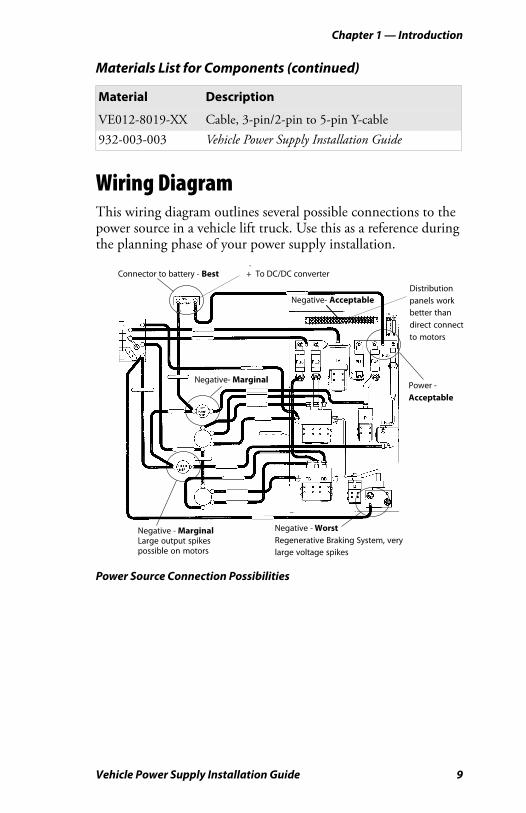
Wiring DiagramThis wiring diagram outlines several possible connections to the power source in a vehicle lift truck. Use this as a reference during the planning phase of your power supply installation.
Power Source Connection Possibilities
VE012-8019-XX Cable, 3-pin/2-pin to 5-pin Y-cable932-003-003 Vehicle Power Supply Installation Guide
Materials List for Components (continued)
Material Description
��������������
������ ������ �������������� �
�� ���������������
�������� ������� ����
����
���� ��
��������� ���� �
��������� ���� ��� ���������������������������� �
�� �!�"!������ ��
������������ ��
!��� �������
�������� �
����� �#��
$� ����������
������ �

Chapter 1 — Introduction
10 Vehicle Power Supply Installation Guide

Vehicle Power Supply Installation Guide 11
2 Installation Process
This chapter outlines mechanical and electrical installation instructions.

Chapter 2 — Installation Process
12 Vehicle Power Supply Installation Guide
Installation RecommendationsReview the lift vehicles to be serviced before you start. Plan the installation following these safety and utility recommendations.
• Install the power cable at the vehicle power source if possible or at the point where the connection is first made to the lift.
• Keep the power cable length as short as possible.
• Connect the negative lead to a point common to any other electronic systems on the lift.
• Verify that the vehicle power source voltage falls within the power supply input voltage rating. See Chapter 1 “Power Supply Options” for identifying information.
• Remember that the kit with the lower input (15-96 VDC) voltage rating, P/N 851-041-003, has a 2-pin input connector.
• Using a mounting bracket for the vehicle power supply simplifies service, since you can take down and replace the entire bracket with another bracket, and troubleshoot the system away from the lift.
• Design a bracket that will be common to multiple lifts and use pre-attached devices to simplify the device installation and service.
Installation SummaryCarry out the primary installation steps in the order outlined here. The sections that follow include detailed steps for each segment of the vehicle power supply installation process.
To install the vehicle power supply
1 Connect the input cable to the power supply.
2 Mechanically install and secure the power supply.
3 Route and secure the power cable.
Warning: Equipment failure or damage will result if the vehicle power source voltage does not fall within the power supply input voltage rating.

Chapter 2 — Installation Process
Vehicle Power Supply Installation Guide 13
4 Shorten cable as appropriate, then crimp the fuse holder to the joined red and black wires (positive). Crimp a terminal ring to the joined white and green wires (negative). Insulate as instructed.
5 Make final connections to the vehicle power source.
Tools Required• Common hand tools (screwdriver set and pliers)
• Heat gun for heat shrink tubing
• Wire crimping and stripping tool
• Electric drill, drill bits
• DC Ohmmeter
Parts List
DescriptionIntermec Part Number Quantity
Power cable 226-340-004 1Fuse holder assembly 315-075-003 1Fuse, 20 A ceramic FB 315-074-003 1Bolt, 3/8-16 x 1-1/2” 800-099-001 2Washer, 3/8” 803-099-001 4Nut, 3/8-16 802-099-001 4Adjustable wire clamps 808-011-001 8Self-tap screw #6 x 5/8” 800-008-003 83/8” terminal ring 809-165-001 2#10 terminal ring 809-083-009 3Self-tab screw #8 x 5/8” 800-012-000 1#8 flat washer 803-084-000 1Snap-in bushing 807-065-003 1Screw, m/s 1/4-20 x 1-1/4” 801-194-002 2Flat washer, 1/4” 803-100-001 2Locking nut, 1/4-20 802-117-000 2Lockwasher, 1/4” 803-042-001 2Cable tie, locking 808-002-000 6

Chapter 2 — Installation Process
14 Vehicle Power Supply Installation Guide
Preparing the Power Input CableOnly one of the input connectors will fit the power supply.
To connect the input cable
1 Mate the corresponding cable connector to the power supply connector.
2 Slide the cable connector in as far as it will go.
3 Turn the cable connector collar clockwise to secure it.
4 Cut the cable at the unused connector end.
5 Discard the unused connector.
6 Remove the cable connector from the power supply with a counterclockwise turn of the cable connector collar.
Additional details for installation are covered later in the section “Cable Termination – Overview of Process” on page 19.
Mounting the Power SupplyThe input power cable is approximately 9.0 ft (2.74 m) long and can be shortened as needed. The output power cable is approximately 7.0 ft (2.13 m) and should not be lengthened.
h/s tubing, black, 1/8” diameter 321-650-003 12.0” (30.5 cm)h/s tubing, black, 3/8” diameter 321-650-006 6.0” (15.2 cm)Ferrite bead 309-065-006 1
Note: The input power cable may be shortened as needed. It should not be extended on 12V or lower systems. On higher voltage systems, extensions should be kept to a minimum and should be of equivalent or lower gauge (larger diameter) wire. Keep the cable as short as possible. Extra cable picks up noise, adds power loss, and is prone to snagging on equipment.
Parts List
DescriptionIntermec Part Number Quantity

Chapter 2 — Installation Process
Vehicle Power Supply Installation Guide 15
You should take these lengths and the intended location of your electronic equipment into consideration when choosing a mounting location for the power supply.
The mounting surface location must provide 130-160 square inches (840 to 1030 square centimeters) of metallic surface to sink heat generated by the power supply. This metallic mounting surface may be connected to or actually be part of the vehicle chassis as long as the chassis is not electrically connected to the battery negative or positive.
Side-Mount Battery with View of Negative (-) and Positive (+).
Direct versus Isolation Mounting on Lift ChassisPreviously, the power supply has been placed directly on the lift chassis. Direct mounting provides both an adequate heat sink and prevents static charge buildup between the metal of the power supply, computer, and lift chassis.
Directly mounting the power supply is the most straight forward installation method. This is also the preferred installation type when there is little risk for other lift accessory devices making electrical contact with the lift chassis.
Electrically isolating the power supply from the chassis maintains conformance to CE requirements.
Note: Lift vehicles in countries requiring CE Mark certification and that have a connection between the battery negative and the lift chassis require additional installation steps.To confirm this requirement, consult the respective lift manufacturer.

Chapter 2 — Installation Process
16 Vehicle Power Supply Installation Guide
Isolating the power supply from the vehicle chassis may provide additional protection from other risks encountered on forklifts or vehicles.
A fault condition like a wire shorting to the lift chassis may present a power path that could negatively impact the power supply and the Intermec computer, as well as any device connected to the shorted wire. While this is an uncommon secondary failure mode, you can avoid this by creating an electrical isolation mount.
Creating a Custom Electrical Isolation MountThere is no kit for isolated mounting solutions, as they are custom to each vehicle installation. Your custom solution should consist of:
• a metal plate 130-160 square inches (840 to 1030 square centimeters) to provide the heat sink for the DC/DC supply.
• a means to mechanically attach this metal plate to the chassis of the vehicle while preventing direct metal to metal contact.
• insulating hardware (plastic shoulder washers or rubber isolators) or an insulating surface (plastic, wood, or rubber) between the power supply and lift chassis.
Mounting the power supply on a metal plate also requires a small resistor (~100 ohms/1W minimum) to be electrically connected between the plate and the chassis of the vehicle to prevent static charge buildup. The isolation hardware and resistor are also not included in the installation kit. See Chapter 1 “Power Supply Options” for more information.
Smaller metallic surfaces may be adequate when good air flow is available or if the vehicle mount computer is to be used in a refrigerated area. Mountings exposed to direct sun may require more heat sink area.
Using a Standard Power Supply MountThis installation kit includes the standard hardware for mounting the power supply.
Use mounting Method A when you can easily access the back side of the mounting location to install a lock nut and washer.

Chapter 2 — Installation Process
Vehicle Power Supply Installation Guide 17
Use Method B where the back side of the mounting location is inaccessible. Note that this method requires that the mounting plate be thick enough to accept and retain sufficient thread to provide a secure and reliable mechanical installation.
To use mounting method A
1 Mark and center punch the two mounting hole locations.
2 Use a 1/4” drill bit to make the two mounting holes.
3 Use 1/4” hex bolts with flat washers and locking nuts to install the power supply.
To use mounting method B:
1 Mark and center punch the two mounting hole locations.
2 Use a #7 drill bit to make the mounting holes.
3 Use a 1/4-20 tap to thread the mounting holes.
4 Place a lock washer on each bolt.
5 Insert the bolt/lock washer assemblies through the power supply holes and into the threaded mounting holes.
Installing the Power CablesFollow these guidelines and other instructions closely when installing power cables.
• Completely install power cables before making connections to equipment.
• Route the power cables from the general area where the power supply will be mounted.
• Use a snap-in bushing (requires a 9/16” hole) if the power cable passes through a firewall or other sheet metal.
• Make sure that cable routing does not interfere with other equipment or vehicle controls.
• Ensure that cable routing does not invite damage to the cable.
Never work on a powered (hot) system.

Chapter 2 — Installation Process
18 Vehicle Power Supply Installation Guide
• Secure the cables at least every 18 inches (46 cm) throughout the cable run. Use adjustable clamps (see the last page in this chapter) or wire-tie to existing vehicle cable runs
Power Cable ConnectionsThe fuse holder from the input power cable must be connected as close as possible, both physically and electrically, to the positive side of the vehicle power source. The remaining colored wires must be connected to the negative side of the vehicle power source.
Instructions are not included for connecting to various possible vehicle power sources. It is assumed that a trained professional installer, knowledgeable on the brands and models of vehicles he or she is working with, will do the installation. Both large (3/8 inch) and smaller terminal rings are provided to accommodate most installation needs.
Warning: If this installation will be on a gas-powered vehicle, you must install either an On/Off switch (minimum 15A DC rating such as ITW P/N 163-900-034) or an automatic shut-off device in series with the in-line fuse holder.
These devices prevent discharge of the vehicle battery while the lift is off.
Charge Guard, Inc. 400 Highland Avenue, Altoona, PA 16602 (814.941.4100) manufactures a CHARGE GUARD™ device for this purpose.
Note: In this installation, the shield wire must be connected to the metal surface on which the power supply is mounted. Prior to connecting power - recheck to make sure the fuse is connected to the positive connection on the DC/DC input, and that the negative lead connects to the return to the battery at a location not shared with motors, flyback diodes, or other sources of electrical noise.

Chapter 2 — Installation Process
Vehicle Power Supply Installation Guide 19
This kit contains additional bolts, nuts, and washers should you need to connect the input power cable directly to a vehicle battery. Use for these parts is detailed in the instructions that follow.
Cable Termination – Overview of ProcessYou must cut the cable to length, cut off a portion of the outer cable jacket, and strip the individual wire ends of the cable as instructed. Heat shrink tubing is furnished in this kit and must be slipped onto the cable or wires before terminating them.
Then, you must install the fuse holder in series with the positive wires and install a terminal ring on the negative wires.
Finally, you must mechanically complete the connections to the vehicle power source or battery and electrically connect the shield wire to the chassis using a self-tapping screw and flat washer.
Preparing the Power CableBe sure the power source is disconnected before starting to work with the cables. All measurements are approximate lengths.
To prepare the power cable
1 Cut the power cable near the power source or battery.
2 Strip the cable jacket back 12-14 inches (30-36 cm).
3 Slide heat shrink tubing over cable jacket.
4 Strip 1/4 inch (0.6 cm) of insulation from individual wires.
5 Twist the white and green (negative) wires together.
6 Twist the red and black (positive) wires together.
7 Twist the shield wire and slide on the 1/8-inch heat shrink tubing.
Note: See the warning on page 18 if you are installing on gas-powered or other 12V vehicles.
Note: The wire colors may not be the same as those shown; therefore, verify all wire connections with an ohmmeter.

Chapter 2 — Installation Process
20 Vehicle Power Supply Installation Guide
Heat Shrink TubingThis kit contains a 6 inch (15 cm) length of 3/8-inch heat shrink tubing which you will cut into three pieces, and a 12 inch (30 cm) length of 1/8-inch heat shrink tubing for the shield wire.
To install heat shrink tubing
1 Crimp terminal rings and fuse holder ends, then position all heat shrink tubing in the locations shown in the illustration that follows.
2 Use a heat gun to shrink tubing.
3 Use the 1/8-inch shrink sleeve tubing over shield wire to prevent contact with other live (powered) circuits.
Note: Make sure that the negative input connector wires connect to pins 1 and 2 of the input connector. Check that the other two wires connect to pins 3 and 4 of the input connector. Be sure to separate and pull out the shield wire.
Note: Tubing must be in place before terminating wire ends.
Green and white wires (negative)
Red and black wires (positive)
Shield wire with heat shrink applied
Strip the cable jacket 12-14 inches (30-36 cm)
Input power cable
Heat shrink tubing
see note below
see note below

Chapter 2 — Installation Process
Vehicle Power Supply Installation Guide 21
Completed Cable Ready for Connection to Vehicle
Finishing the Cable EndsBoth large (3/8 inch) and small (#10) terminal rings are provided in the kit. A small (#10) terminal should be crimped to the shield wire and then fastened to the vehicle chassis.
To prepare the cable ends
1 Strip 1/4 inch (0.6 cm) of insulation from individual wires.
2 Crimp the terminal ring onto white-green twisted pair (negative).
3 Crimp one end of the fuse block on the red-black twisted pair (positive).
Crimp a similar gauge wire or twisted pair of wires onto the other end of the fuse block and then a terminal ring on the other end of this wire (see previous Completed Cable illustration).
4 Crimp the small terminal ring on the shield wire.
Note: Be sure to attach shield wire to the metal surface on which the power supply is mounted.
All crimps should be checked to ensure the wire is completely captured in the terminal ring or fuse holder. Loose connections will fail.
1/8”
3/8” 3/8” 3/8”
Shield Wire - see Note below
Green and white twisted pair
Red and black twisted pair

Chapter 2 — Installation Process
22 Vehicle Power Supply Installation Guide
Power Source ConnectionsThe next few pages show you the hardware (nuts, bolts, and washers) included in this kit if you are connecting the power cable directly to a vehicle battery.
Direct Battery ConnectionsYour vehicle has either a side-mount battery with the terminals on the side or a top-mount battery with the terminals on the top. Determine which battery is in your vehicle and proceed with the applicable instructions.
Side-Mount Battery TerminalsAttach the vehicle battery cable to a side-mount battery terminal as shown in the “Side-Mount Battery Terminals” illustration following the last step in this set of procedures.
To attach power supply cable
1 Disconnect the negative battery cable, then disconnect the positive battery cable, and remove the bolts from each cable.
2 Screw a 3/8-inch nut as far as it will go onto a 3/8 x 1-1/2-inch bolt furnished in the kit, then slip a 3/8-inch washer onto the bolt.
3 Slide the positive (red wire with fuse link) terminal ring from the power input cable onto the bolt.
4 Slip a second 3/8-inch washer onto that bolt.
5 Slide the vehicle positive battery cable onto the bolt.
6 Thread the bolt assembly (steps 2-5, above) into the positive (+) battery terminal. Securely tighten but do not overtighten the bolt.
7 Tighten the nut securely against the washers and cables.
8 Use a self-tapping screw and flat washer to connect shield wire to the metal surface on which the power supply is mounted.
Note: No additional hardware is provided for connecting the power cable to other vehicle power sources. See your vehicle manufacturer’s technical manual if necessary.

Chapter 2 — Installation Process
Vehicle Power Supply Installation Guide 23
Repeat steps 2 through 8 for the negative wire (white-green pair) from the power input cable, connecting the wire to the negative (-) battery terminal.
Side-Mount Battery Terminals
Top-Mount TerminalsAttach the vehicle battery cable to a top-mount battery terminal as shown in the “Top-Mount Battery Terminals” illustration following the last step in this set of procedures.
To attach power supply cable
1 Disconnect the negative battery cable, then disconnect the positive battery cable.
2 Remove the bolts from the vehicle battery terminals.
3 Replace those bolts with 3/8x1-1/2-inch bolts and nuts from the installation kit. Tighten the nuts.
Note: See the warning on page 18 if you are installing on gas-powered vehicles.
3/8” nut
3/8 x 1-1/2” bolt
Vehicle battery
Fuse holder
3/8” washers
Vehicle battery cable

Chapter 2 — Installation Process
24 Vehicle Power Supply Installation Guide
4 Reinstall the positive battery cable, then tighten the nut securely.
5 Slip a 3/8-inch washer onto the extended end of each bolt.
6 Slide the positive (fuse link with red wire) terminal ring from the input power cable onto the positive (+) battery bolt.
7 Slip a second 3/8-inch washer onto that bolt.
8 Thread and tighten a second 3/8-inch nut onto that bolt.
9 Use a self-tapping screw and a flat washer to connect the shield wire to the metal surface on which the power supply is mounted.
Repeat steps 6 through 8 for the negative battery cable wire (white-green pair) from the power input cable, connecting the wire to the negative (-) battery terminal.
Top-Mount Battery Terminals
Bolt
NutVehicle battery
Vehicle battery cable
Fuse holder
Washers

Chapter 2 — Installation Process
Vehicle Power Supply Installation Guide 25
Cable ClampsSecure the cables every 18 inches (46 cm) using locking wire ties or adjustable cable clamps.
To install cable clamps
1 Remove the paper backing from a clamp and adhere the clamp in place.
2 Drill a pilot hole with a #26 drill bit and use #6 sheet metal screws to permanently hold each clamp in place.
Recommended Grounding and Power Source Connections
Connecting the Output Power CableOnce the computer, dock, or other device is mechanically installed, you can connect the output power cable between the power supply output and the device. Connectors are keyed and operate the same as the input power connector.
To finish the connection
1 Mate the cable connector to the power supply and to the device connectors.
2 Slide the cable connector as far as it will go into the power supply.
3 Turn the cable connector collar clockwise to secure it.
4 After all connections are secure, connect power to the system.Note: See “Troubleshooting Charts” on page 32 for power fault diagnostic information.
#6 sheet metal screw goes here

Chapter 2 — Installation Process
26 Vehicle Power Supply Installation Guide
Sample InstallationsIn this installation example, the power supply is securely attached with good air flow, easy access, and neatly tied-off cabling.
Additionally, this installation allows:
• Easy access to power supply components, LED visibility is good.
• Power cables are out of the way and tied off, with adequate heat sink, and good air access for cooling.
• Good access for component service.
• Full access to the UPS battery.

Chapter 2 — Installation Process
Vehicle Power Supply Installation Guide 27
Here is another example of an effective installation.
In this example, the benefits include:
• UPS is accessible without disconnecting it from the lift.
• Battery swap is accommodated without removing the UPS entirely.
• Metal area contact is reduced, but ventilation is good, reducing the need for additional heat sink.
• No direct sunlight in this environment helps maintain lower operating temperature.

Chapter 2 — Installation Process
28 Vehicle Power Supply Installation Guide
A poorly planned installation presents several challenges, including:
• Difficult access to power supply components, LED visibility in operation is impossible.
• Damage could occur to lift or power supply components if something fails.
• UPS battery removal is difficult due to location.
• The installation is tedious, time-consuming, and difficult to work on.
• Troubleshooting problems made difficult.
• An enclosed environment will significantly reduce the air flow, raising the temperatures of all the components.

Vehicle Power Supply Installation Guide 29
3 Troubleshooting Information
This chapter contains troubleshooting information and connector pin outs.

Chapter 3 — Troubleshooting Information
30 Vehicle Power Supply Installation Guide
Identifying and Correcting ProblemsThree basic procedures within this chapter identify and correct most power supply problems you may encounter during installation. Connector pin-out information is also furnished for your convenience.
The recommended diagnostic procedures listed below should be followed in the order given. Troubleshooting charts indicate when you should use a particular method.
Troubleshooting the Power SupplyBasic diagnostic procedures include the following:
• Inspection
• Electrical (voltage and continuity) measurements
• Component substitution
Inspecting the Power SupplyThe power supply has one or two green light-emitting diode (LED) indicators near the output connector.
The Main Output LED is lit when 12 VDC is present at the output connector. If you suspect a power failure, check for the following:
• If the LED is not lit, the power supply is not producing 12 VDC output power. In this case, a fault can exist anywhere in the system. See the “Troubleshooting Charts” on page 32, to isolate, identify, and correct the fault.
• If the LED is lit, yet you suspect a power failure, check either the output cable or further downstream from it.
• If the LED is flickering, the power supply has detected a fault condition related to temperature, voltage, or current. The LED will flicker until the problem is resolved. In some cases, you may have to remove power to reset the power supply.
Inspecting the Cables and ConnectionsVisually inspect all cable connectors and connections to the vehicle power source. Correct any obvious faults.
• Use your hands to wiggle cable connectors to ensure they are not loose or disconnected. Again, correct any faults before proceeding.

Chapter 3 — Troubleshooting Information
Vehicle Power Supply Installation Guide 31
• Make sure cables are adequately dressed (protected) to go around sharp edges, through holes without burrs, and do not run unprotected around the lift.
• The sheath of the power cable adds protection from accidental nicks and cuts. Additional sheathing may be beneficial to protect the cables in highly vulnerable locations.
Inspecting the FuseOpen the twist-lock fuse holder and remove the fuse for a continuity test. If you substitute a new fuse and fails (blows), check for the most likely causes:
• Shorted or mis-wired input cable.
• Faulty or (incorrect) power supply.
Using Electrical MeasurementsMeasuring for voltageConnector pinout information is provided to aid measuring voltage at the input power cable connector and at either end of the power output cable.
Testing for continuity
Thorough continuity testing takes longer than either substitution or voltage measurements. An ohmmeter is sufficient to diagnose simple opens or shorts.
If fuses blow sporadically, or power supply shut down occurs at random, you may want to use a megohmmeter to check cables for high-resistance shorts between wires or between a wire and the cable shield. See the “Troubleshooting Charts” on page 32 for more information.
Caution: Cables must be disconnected at both ends before you conduct any continuity tests.
Failure to disconnect cables completely may result in damage or destruction of your test equipment, or incorrect/misleading readings.
Chapter 3 — Troubleshooting Information
32 Vehicle Power Supply Installation Guide
Using Component SubstitutionComponent substitution is the most expedient and certain troubleshooting technique.This is especially valuable when trying to resolve intermittent problems.
• Use the guidelines in the following troubleshooting charts, substituting only when directed to do so.
• If an installation suffers intermittent input power fuse failures, or if the power supply shuts down without good cause, do not hesitate to substitute a known good power supply.
• The disadvantage of component substitution is that you must either have spare parts (power supply and both cables in this instance) or be prepared to take components from another working installation.
Troubleshooting ChartsThe following troubleshooting chart assumes that your vehicle mount computer or other equipment does not work and that the problem is caused by the power supply or its associated cables
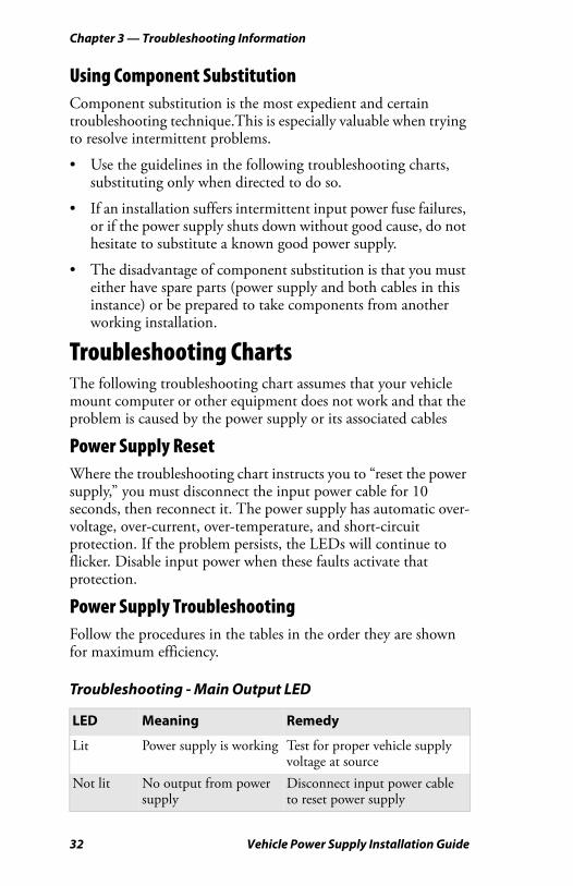
Power Supply ResetWhere the troubleshooting chart instructs you to “reset the power supply,” you must disconnect the input power cable for 10 seconds, then reconnect it. The power supply has automatic over-voltage, over-current, over-temperature, and short-circuit protection. If the problem persists, the LEDs will continue to flicker. Disable input power when these faults activate that protection.
Power Supply TroubleshootingFollow the procedures in the tables in the order they are shown for maximum efficiency.
Troubleshooting - Main Output LED
LED Meaning Remedy
Lit Power supply is working Test for proper vehicle supply voltage at source
Not lit No output from power supply
Disconnect input power cable to reset power supply

Chapter 3 — Troubleshooting Information
Vehicle Power Supply Installation Guide 33
Advanced TroubleshootingAssuming steps in the previous troubleshooting chart were taken, proceed to these next steps to resolve power failure problems.
Still not lit Still no output from power supply
Disconnect power output cable, reset the power supply, check fuse
Flickers Intermittent main power connection
Check connection to main power source
Flickers Power supply detected over-voltage condition
Vehicle noise spikes exceeding voltage rating for power supply. Work with your forklift manufacturer to look for alternate power connection locations. Check to see whether they have any recommended in-line filters or suppressors.
Flickers Power supply detected over-current condition
Disconnect the output cable. If the flickering stops, check the cables and add downstream elements. Disconnect the UPS if one is present. Bypass the UPS if one is present. If the flickering stops, replace the UPS.
Flickers Power supply detected over-temperature condition
Check case temperature of the power supply. If too hot to touch, provide better heat sink and more air flow. Replace damaged cables. Protect from direct sunlight, mount in the shade.
Advanced Troubleshooting Steps
LED/Voltage Meaning Test or Remedy
LED not lit No output from power supply
Test for input voltage
No output voltage, input normal
Power supply not working
Replace power supply
Troubleshooting - Main Output LED (continued)
LED Meaning Remedy
Chapter 3 — Troubleshooting Information
34 Vehicle Power Supply Installation Guide
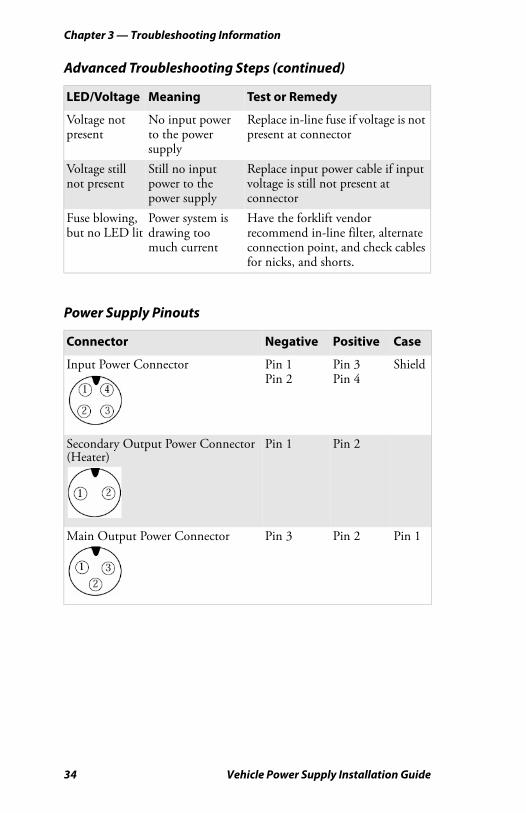
Voltage not present
No input power to the power supply
Replace in-line fuse if voltage is not present at connector
Voltage still not present
Still no input power to the power supply
Replace input power cable if input voltage is still not present at connector
Fuse blowing, but no LED lit
Power system is drawing too much current
Have the forklift vendor recommend in-line filter, alternate connection point, and check cables for nicks, and shorts.
Power Supply Pinouts
Connector Negative Positive Case
Input Power Connector Pin 1Pin 2
Pin 3Pin 4
Shield
Secondary Output Power Connector (Heater)
Pin 1 Pin 2
Main Output Power Connector Pin 3 Pin 2 Pin 1
Advanced Troubleshooting Steps (continued)
LED/Voltage Meaning Test or Remedy

Chapter 3 — Troubleshooting Information
Vehicle Power Supply Installation Guide 35
Wire coloring to pins follows this pattern.
Note: During installation, you will cut and discard one of these cable connectors.
Note: The cables in the installation kit may contain alternate wire colors. Refer to the following chart for the wire color equivalent.
Wire Color Equivalents
Wire Color Alternate Color
Green BlueWhite GrayRed BrownBlack Red
P/N 226-340-003 and 226-340-004108.0 +/- 3.0”
2 14
3
2
1Pin View2-Pin View
1
2
1
2
3
4

Chapter 3 — Troubleshooting Information
36 Vehicle Power Supply Installation Guide

Chapter 3 — Troubleshooting Information
Vehicle Power Supply Installation Guide 37

Vehicle Power Supply Installation Guide
*932-003-003*P/N 932-003-003
Worldwide Headquarters6001 36th Avenue WestEverett, Washington 98203U.S.A.
tel 425.348.2600
fax 425.355.9551
www.intermec.com
© 2007 Intermec TechnologiesCorporation. All rights reserved.