installation inal oost i
TRANSCRIPT

Signal BoosterInstallationGuide
AG Pro 75™
Smart Technology™In-BuildingWireless 800/1900 Signal Booster
Contents:Before Getting Started . . . . . . . . . . . . . . . . . . . . . . . . . . . . 1Antenna Options & Accessories . . . . . . . . . . . . . . . . . . . . 1Easy Installation Overview . . . . . . . . . . . . . . . . . . . . . . . . 2Installation Diagram . . . . . . . . . . . . . . . . . . . . . . . . . . . . . . 2Powering Up a Wilson Signal Booster . . . . . . . . . . . . . . . . 3Understanding the Signal Booster Lights . . . . . . . . . . . . . 4Warnings and Recommendations . . . . . . . . . . . . . . . . . . . 5Reasons for Weak Cellular Signals . . . . . . . . . . . . . . . . . . 5Guarantee and Warranty . . . . . . . . . . . . . . . . . . . . . . . . . . 6Signal Booster Specifications . . . . . . . . . . . . . .Back Cover
Wilson®
Electronics, Inc.
Note: This manual contains important safety and operating information . Please read and follow the instructions in this manual . Failure to do so could be hazardous and result in damage to your signal booster .
ROU
GH
DRA
FT
1 Contact Wilson Electronics Technical Support Team with any questions at 866-294-1660 or email: [email protected]. Hours: 7 am to 6 pm MST. 2
Installation Instructions for the Following Wilson Signal Booster:
AG Pro 75™ Smart Technology™ In-Building Wireless 800/1900 Signal BoosterModel # 271265FCC ID: PWO271265 IC: 4726A-271265
The term “IC” before the radio certification number only signifies that Industry Canada technical specifications were met .
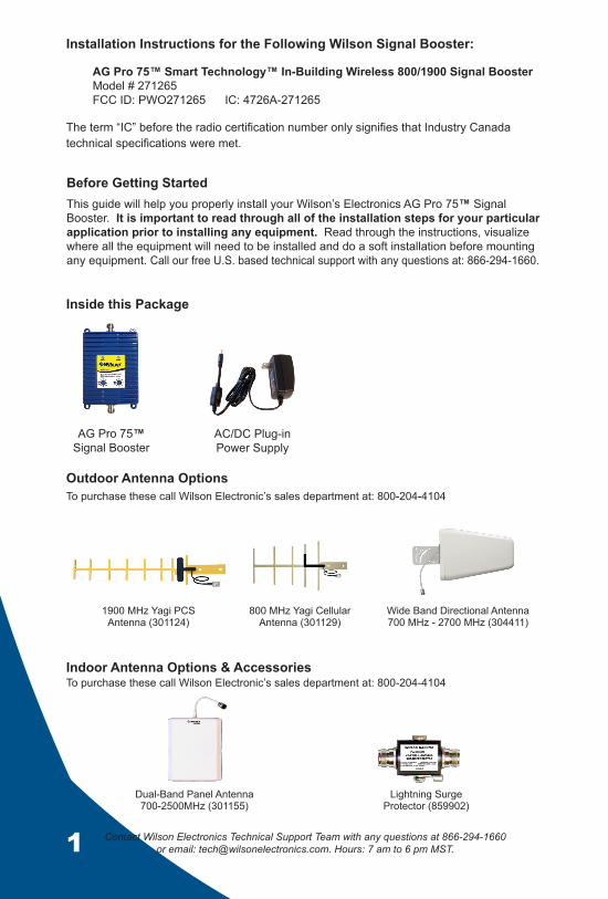
Inside this Package
AG Pro 75™ Signal Booster
AC/DC Plug-in Power Supply
Outdoor Antenna Options
Indoor Antenna Options & Accessories
Before Getting StartedThis guide will help you properly install your Wilson’s Electronics AG Pro 75™ Signal Booster . It is important to read through all of the installation steps for your particular application prior to installing any equipment. Read through the instructions, visualize where all the equipment will need to be installed and do a soft installation before mounting any equipment . Call our free U .S . based technical support with any questions at: 866-294-1660 .
To purchase these call Wilson Electronic’s sales department at: 800-204-4104
To purchase these call Wilson Electronic’s sales department at: 800-204-4104
1900 MHz Yagi PCS Antenna (301124)
800 MHz Yagi Cellular Antenna (301129)
Wide Band Directional Antenna 700 MHz - 2700 MHz (304411)
Dual-Band Panel Antenna 700-2500MHz (301155)
Lightning Surge Protector (859902)

1 2Contact Wilson Electronics Technical Support Team with any questions at 866-294-1660 or email: [email protected]. Hours: 7 am to 6 pm MST.
Typical Installation
Power Supply
Signal booster
Lightning Surge ProtectorInside Antenna
Minimum separation distance 50 feet
Outside Antenna
Select a location to install the signal booster that is away from excessive heat, direct 1 . sunlight, moisture and has proper ventilation . Do not place the signal booster in an air-tight enclosure . Select a location on the roof of the building to install the outside antenna . Use a cell phone 2 . in test mode to find the strongest signal from the cell tower . Visit www .wilsonelectronics.com to find test mode function for your particular cell phone .Select a location for the inside antenna, preferably in the center of where the signal 3 . needs to be amplified . Separation distance between inside and outside antennas must be a minimum of 50 feet .Run the outside antenna cable to the signal booster and attach it to the connector 4 . labeled “outside antenna” on the signal booster . Run the inside antenna cable to the signal booster and attach it to the connector labeled “inside antenna” on the signal booster . Note: Be careful when plugging the connector in so as not to bend the center pins on the connectors. Verify that both the outside antenna and the inside antenna are connected and check 5 . that all connections are tight, before powering up the signal booster . Lightning surge protection is recommended for all in-building installations .AG Pro 75™ Signal Booster has been packaged with the gain control knobs adjusted 6 . to the highest gain position . If one or both of the lights are blinking red please refer to page 4 .Warning: 7. Connecting the signal booster directly to a cell phone with use of an adapter will damage the cell phone .
Easy InstallationContact Wilson Electronics Technical Support Team with any questions at 866-294-1660 .

3 Contact Wilson Electronics Technical Support Team with any questions at 866-294-1660 or email: [email protected]. Hours: 7 am to 6 pm MST. 4
Powering up a Wilson Electronics Signal Booster
1 . To verify proper installation of the signal booster and antennas, make sure that the distance between the inside and outside antennas is a minimum of 50 feet .
2 . Never point the front of a directional antenna toward the other, inside or outside, antenna . See Figure 1 below .
3 . Ensure that both the outside antenna coax cable and the inside antenna coax cable are connected to the signal booster and the connections are tight before powering up the signal booster .
4 . Plug the 6-volt power supply into the signal booster input marked “6V DC” (carefully, to avoid damaging the center pin) and then into a wall outlet .
5 . If the signal booster has a red light, or a blinking red light, please see page 4 .
6 . If you know that only one frequency band (800 or 1900) is available in your coverage area (or going to be used), reduce the gain control on the frequency band that is NOT in use to the minimum . This will reduce the power consumption of the signal booster .
7 . Using multiple boosters in one installation could cause degraded cell tower operation .
8 . Contact Wilson Electronics Technical Support Team with any questions at 866-294-1660, or email at tech@wilsonelectronics .com . Technical Support hours are 7 am until 6 pm MST .
Signal booster
OutdoorAntenna
PanelAntenna
Figure 1
INCORRECT INSTALLATIONNever point antennas toward each other

3 4Contact Wilson Electronics Technical Support Team with any questions at 866-294-1660 or email: [email protected]. Hours: 7 am to 6 pm MST.
Understanding the Signal Booster Lights and Troubleshooting
1. BLINkING GREENIf the signal booster is blinking green, the signal booster is operating properly . If you are happy with the coverage area in your building, then you are done .
2. BLINkING REdThe signal booster is experiencing receiver overload, see troubleshooting tips below .
3. SOLId REdThe signal booster has shut down to prevent an oscillation, see troubleshooting tips below .
If after the initial 15 minutes you are not done with the installation, the signal booster can be reset and enter installation mode again by disconnecting and reconnecting the power supply from the booster .
Troubleshooting Tips
GREENThe indicator lights on the signal booster will be a solid green when the unit is powered up and working properly . (After the 15 minute installation period) .
BLINkING REd LIGhTThe signal booster has protection shut off circuits to prevent the disruption of cell towers. If one or both lights are blinking red, this indicates that the signal from a cell tower is overloading the booster and the booster has shut down on that frequency.
Reposition the outside antenna away from the cell tower, or turn the gain control knob counter clockwise to reduce the gain until the light turns green .
If the red light is still blinking with the gain control adjusted all the way counter clockwise, contact Wilson Electronics Technical Support Team for assistance: 866-294-1660 .
SOLId REdIf the signal booster indicator light is a solid red, this indicates the booster has shut down on the frequency indicated to prevent an oscillation . First, make sure that all the connections are tight . Then move the inside and outside antennas farther apart or reduce the gain of the booster by rotating the gain control, corresponding to the red light, counter clockwise until the light turns green .
When you are turning down the gain, you are reducing the inside coverage area . If after turning down the gain, your coverage area is too small, and you want it larger, then move the inside and outside antennas farther apart until the gain can be raised .
During installation mode the signal booster is resetting itself very quickly to aid the installer . The Signal Booster is equipped with two indicator lights, one for the 800 MHz band and the other for the 1900 MHz band . For the first 15 minutes that the booster is plugged in, it is programed for a test and alignment period . During this time, both lights will do one of the following 3 things:

5 Contact Wilson Electronics Technical Support Team with any questions at 866-294-1660 or email: [email protected]. Hours: 7 am to 6 pm MST. 6
Warnings and Recommendations
Warning: The Directional antenna must always be located so the back or side points to the inside antenna . Never point the front of the Directional antenna toward the inside antenna – this is to prevent oscillation .
Warning: Connecting the signal booster directly to the cell phone with use of an adapter will damage the cell phone .
Warning: Connect both the outside and inside antenna cables to the signal booster before powering up the signal booster .
Warning: Use only the power supply provided in this package . Use of a non-Wilson Electronics product may damage your equipment .
Warning: RF Safety: FCC regulations require that any fixed outside antenna used with this signal booster may not have gain (less cable loss) that exceeds 15 dBi and must be located at least 30 inches from all people . Inside antennas must not exceed 7 dBi gain (less cable loss) in the 800 MHz band or 10 dBi gain (less cable loss) in the 1900 MHz band and must be located at least 8 inches from all people .
Warning: Verify that both the outside antenna and the inside antenna are connected to the signal booster before powering up the signal booster .
Note: Lightning surge protection is recommended for all in-building installations.
Reasons for Weak Cellular Signals
Anyone who uses a cell phone or cellular data card knows the frustration of not being able to connect to or maintain a strong cellular signal . When this occurs, it is generally due to one of two reasons:
1 . Location of the Nearest Cell Tower – Cell towers are situated to provide broad coverage; however, there are many areas in which signal strength may be reduced by placement of the towers themselves or local government restrictions on the height . Rural areas generally have fewer cell towers than urban regions .
2 . Natural and Man-Made Obstructions – Signal strength can also be negatively affected by trees, hills, weather, buildings and other obstructions . You may be relatively close to a cell tower but still unable to make a call . This often occurs in homes, offices and other buildings in which stucco, concrete or metal walls may block the signal .
Your booster works with two antennas . The inside antenna communicates with your cell phone and the outside antenna communicates with the cell tower .
The outside antenna receives the outside signal and sends it through the coax cable to the booster, where it is amplified and transmitted through the inside antenna into the room . When the inside antenna picks up a signal from your cell phone, the signal booster amplifies that signal and transmits it through the cable to the outside antenna and back to the cell tower . Note: The booster will only boost if a signal is available .
5 6Contact Wilson Electronics Technical Support Team with any questions at 866-294-1660 or email: [email protected]. Hours: 7 am to 6 pm MST.
30-day Money-Back Guarantee
All Wilson Electronics products are protected by Wilson Electronics 30-day money-back guarantee . If for any reason the performance of any product is not acceptable, simply return the product directly to the reseller with a dated proof of purchase .
1-Year Warranty
Wilson Electronics Signal Boosters are warranted for one (1) year against defects in workmanship and/or materials . Warranty cases may be resolved by returning the product directly to the reseller with a dated proof of purchase .
Signal Boosters may also be returned directly to the manufacturer at the consumer’s expense, with a dated proof of purchase and a Returned Material Authorization (RMA) number supplied by Wilson Electronics . Wilson Electronics shall, at its option, either repair or replace the product . Wilson Electronics will pay for delivery of the repaired or replaced product back to the original consumer if located within the continental U .S .
This warranty does not apply to any signal booster determined by Wilson Electronics to have been subjected to misuse, abuse, neglect, or mishandling that alters or damages physical or electronic properties .
RMA numbers may be obtained by phoning Technical Support at 866-294-1660 .
Operation is subject to the following two conditions: (1) This device may not cause interference and (2) this device must accept any interference, including interference that may cause undesired operation of this device .
Disclaimer: The information provided by Wilson Electronics, Inc . is believed to be complete and accurate . However, no responsibility is assumed by Wilson Electronics, Inc . for any business or personal losses arising from its use, or for any infringements of patents or other rights of third parties that may result from its use .
Copyright © 2010 Wilson Electronics, Inc . All rights reserved .

AIG #110769 - 01 - 12/3/10
AG Pro75™ Specifications
IC: 4726A-271265FCC Id: PWO271265
dual-Band Wireless800/1900 Mhz Specifications
Model Number 271265
Antenna connectors N-Female
Antenna impedance 50 ohms
Dimensions 5 .7 x 4 .2 x 1 .5 inch (14 .0 x 10 .8 x 3 .9 cm)
Weight 1 .27 lbs (0 .544 kg)
Frequency 824-894 MHz / 1850-1990 MHz
1Passband Gain (nominal)
800 MHz * 1900 MHz 70 dB Typical, 75 dB Maximum
220 dB Bandwidth (nominal) Downlink
800 MHz 45 MHz
1900 MHz 88 MHz
Power Output 800 MHz 1900 MHz
Power output for single cell phone (uplink) 30 .8 dBm 30 .5 dBm
Power output for single received channel (downlink) 26 .0 dBm 25 .2 dBm
4Power output for multiple transmitted channels (uplink) Maximum Power
The maximum power is reduced by the number of channels: Number of channels 800 MHz 1900 MHz
2 24 .0 dBm 21 .3 dBm
3 20 .5 dBm 17 .8 dBm
4 18 .0 dBm 15 .3 dBm
5 16 .0 dBm 13 .3 dBm
6 14 .5 dBm 11 .8 dBm
4Power output for multiple received channels (downlink) Maximum Power
The maximum power is reduced by the number of channels: Number of channels 800 MHz 1900 MHz
2 24 .8 dBm 23 .7 dBm
3 21 .3 dBm 20 .2 dBm
4 18 .8 dBm 17 .7 dBm
5 16 .8 dBm 15 .7 dBm
6 15 .3 dBm 14 .2 dBm
Noise Figure (typical downlink/uplink) 3 .5 dB nominal / 6 dB nominal
Isolation > 90 dB
Power Requirements 110-240 V AC, 50-60 Hz, 8 W
Notes: 1 . Nominal gain is the maximum gain at any frequency in the passband . 2 . Nominal bandwidth is the difference between two frequencies that are adjacent to the passband where the amplification is 20 dB lower than the passband amplification . One of the frequencies is lower than the passband and the other is higher . 3 . The Manufacturer’s rated output power of this equipment is for single carrier operation . For situations when multiple carrier signals are present, the rating would have to be reduced by 3 .5 dB, especially where the output signal is re-radiated and can cause interference to adjacent band users . This power reduction is to be by means of input power or gain reduction and not by an attenuator at the output of the device . 4 . The maximum power for 2 or more simultaneous signals will be reduced by 6 dB every time the number of signals is doubled .
3301 East Deseret Drive, St . George UT 84790For additional Technical Support visit www .wilsonelectronics .com
or email at: tech@wilsonelectronics .comPhone: 866-294-1660 Local: 435-673-5021 Fax: 435-656-2432
www .twitter .com/WilsonCellular www .facebook .com/WilsonCellular