installation instructions ceiling-suspended basketball ... · installation instructions...
TRANSCRIPT

Installation InstructionsCeiling-Suspended Basketball Backstops
Copyright ©2013 Draper Inc. Form EZFold-Ceiling_Inst13-R Printed in U.S.A.If you encounter any difficulties installing or service your EZ-Fold® backstop, call your dealer or Draper, Inc., Spiceland, Ind., (765) 987-7999; or fax (765) 987-7142.
®

EZ-Fold Basketball Backstops by Draper—Ceiling-Suspended Page 2 of 34
www.draperinc.com (765) 987-7999
For Beam attachments, loosely bolt one spacer flat to mounting plate (for winch, safety belt, or other), and bolt one end of spacer flat to other side. Slide bolted end onto beam, then rotate other spacer flat over other side of beam (see Fig. G-2). Tighten bolts.
Tools Needed-Block and tackle-9/16" and 3/4" wrenches, or-Socket wrenches, with socket sizes 9/16" and 3/4"-Chalk line-Plumb bob or laser plumb pointer-Tape measure (minimum 100')-Needle-nose pliers-Screwdrivers (Phillips and flat-head)-Allen wrenches-Impact tool-Scaffolding and/or lift-Carpenter’s Level-Electric drill (9/16" and 9/32" bits)-Electric saw-Wire cutters
How to Use This Manual This manual covers installation of all Draper EZ-Fold® backstops, and is designed to be used in conjunction with project drawings. Project drawings provided by Draper, Inc., show clamp numbers and positions for each backstop on a job. Begin at step 1, the top, and work your way down, following assembly instructions for clamps provided for each specific installation.
Use your project drawings. Draper provides the industry’s best and most comprehensive project drawings, which will tell you everything from exact locations to what clamps to use. If the drawing is to scale, the scale can always be found at the bottom of the drawing. Mark superstructure dimensions on floor using a chalk line, then use a plumb bob to transfer those marks to the roof. Use blue chalk color (won’t stain floor). After snapping chalk lines, place clear plastic throws on the floor. This will protect the floor, while allowing you to see the chalk lines. All dimensions are referenced from Face of Bank, Center Line of Court, Center Line of Backstop Main Stem, or Center of Clamp. Refer to project drawings for dimensions. Remember to account for offset dimensions (Center of Clamp to Edge of Clamp) when mark- ing beams for clamp placement, and especially when installing bent stem models. Prior to assembly, distribute parts to the correct backstop locations. Backstops may differ in model number or dimension; make sure you have the proper parts for each backstop location. All Draper Gymnasium Equipment is supplied with Grade 5 hard- ware. Clamps are designed to be installed with the nuts and bolts “tight.” Draper would consider tight to be torques between 40 ft-lbs and 60 ft-lbs.Please Note: When assembling T-Frames, place Top-of-T on two overturned five gallon buckets; place bottom of stem on casters or a small wheeled cart.
These instructions are meant as a guide only. They do not bind Draper, Inc. in any way and do not imply any responsibility of Draper, Inc. for improper installation or faulty workmanship at the jobsite.
Fig. G-1
Step 1
Step 2
Top View
Fig. G-2
Caution When laying out parts, be careful not to place them where they may be in the way of scaffolding, lifts or working areas. To reduce the risk of injury to those working below, take only tools required for attaching Truss to roof. Before beginning assembly, locate and identify all parts using hardware list and project drawings. Backstops must be installed level and plumb. Do not operate folding backstops unless safety belt has been installed (if safety belt is part of job). Make sure power is disconnected before wiring winches. Do not install damaged or defective parts.
Installation Tips Whenever possible, install bolts with heads toward the floor (threads pointed up), or with heads toward the front (threads facing rear of backstop). Assemble backstop (Ceiling-Suspended only) on the floor, then hoist into attachment position. There are several options for hoist- ing. Use extreme caution.
For tube attachments, loosely bolt one side of clamp together, hold tube in place, swing bottom of clamp around, add second bolt and finish bolting (see Fig. G-1).
Caution: Draper, Inc., is not responsible for roof strength. Do not install truss if roof is not strong enough to bear stress loads required for backstop.
Caution: Draper, Inc., is not responsible for wall strength. Do not install wall pads if wall is not strong enough to bear stress loads required for backstop. Attachment method to be deter-mined by project architect/engineer. Attachment hardware pro-vided by others.
EZ-Fold Basketball Backstops by Draper—Ceiling-Suspended Page 3 of 34
www.draperinc.com (765) 987-7999
EZ-Fold® Backstops by DraperOperation and Maintenance (Ceiling-Suspended)
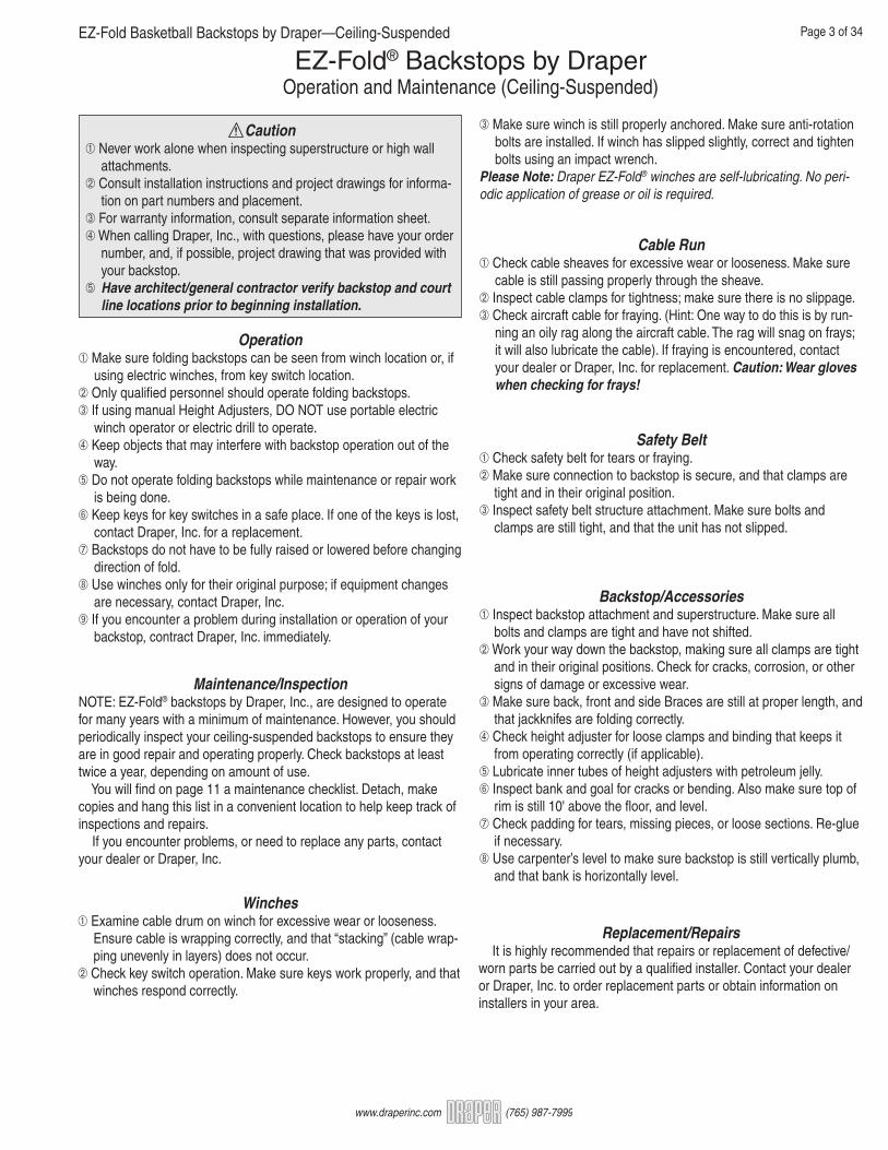
Operation Make sure folding backstops can be seen from winch location or, if using electric winches, from key switch location. Only qualified personnel should operate folding backstops. If using manual Height Adjusters, DO NOT use portable electric winch operator or electric drill to operate. Keep objects that may interfere with backstop operation out of the way. Do not operate folding backstops while maintenance or repair work is being done. Keep keys for key switches in a safe place. If one of the keys is lost, contact Draper, Inc. for a replacement. Backstops do not have to be fully raised or lowered before changing direction of fold. Use winches only for their original purpose; if equipment changes are necessary, contact Draper, Inc. If you encounter a problem during installation or operation of your backstop, contract Draper, Inc. immediately.
Maintenance/InspectionNOTE: EZ-Fold® backstops by Draper, Inc., are designed to operate for many years with a minimum of maintenance. However, you should periodically inspect your ceiling-suspended backstops to ensure they are in good repair and operating properly. Check backstops at least twice a year, depending on amount of use. You will find on page 11 a maintenance checklist. Detach, make copies and hang this list in a convenient location to help keep track of inspections and repairs. If you encounter problems, or need to replace any parts, contact your dealer or Draper, Inc.
Cable Run Check cable sheaves for excessive wear or looseness. Make sure cable is still passing properly through the sheave. Inspect cable clamps for tightness; make sure there is no slippage. Check aircraft cable for fraying. (Hint: One way to do this is by run- ning an oily rag along the aircraft cable. The rag will snag on frays; it will also lubricate the cable). If fraying is encountered, contact your dealer or Draper, Inc. for replacement. Caution: Wear gloves when checking for frays!
Winches Examine cable drum on winch for excessive wear or looseness. Ensure cable is wrapping correctly, and that “stacking” (cable wrap- ping unevenly in layers) does not occur. Check key switch operation. Make sure keys work properly, and that winches respond correctly.
Safety Belt Check safety belt for tears or fraying. Make sure connection to backstop is secure, and that clamps are tight and in their original position. Inspect safety belt structure attachment. Make sure bolts and clamps are still tight, and that the unit has not slipped.
Backstop/Accessories Inspect backstop attachment and superstructure. Make sure all bolts and clamps are tight and have not shifted. Work your way down the backstop, making sure all clamps are tight and in their original positions. Check for cracks, corrosion, or other signs of damage or excessive wear. Make sure back, front and side Braces are still at proper length, and that jackknifes are folding correctly. Check height adjuster for loose clamps and binding that keeps it from operating correctly (if applicable). Lubricate inner tubes of height adjusters with petroleum jelly. Inspect bank and goal for cracks or bending. Also make sure top of rim is still 10' above the floor, and level. Check padding for tears, missing pieces, or loose sections. Re-glue if necessary. Use carpenter’s level to make sure backstop is still vertically plumb, and that bank is horizontally level.
Replacement/Repairs It is highly recommended that repairs or replacement of defective/worn parts be carried out by a qualified installer. Contact your dealer or Draper, Inc. to order replacement parts or obtain information on installers in your area.
Make sure winch is still properly anchored. Make sure anti-rotation bolts are installed. If winch has slipped slightly, correct and tighten bolts using an impact wrench.Please Note: Draper EZ-Fold® winches are self-lubricating. No peri-odic application of grease or oil is required.
Caution Never work alone when inspecting superstructure or high wall attachments. Consult installation instructions and project drawings for informa- tion on part numbers and placement. For warranty information, consult separate information sheet. When calling Draper, Inc., with questions, please have your order number, and, if possible, project drawing that was provided with your backstop. Have architect/general contractor verify backstop and court line locations prior to beginning installation.
EZ-Fold Basketball Backstops by Draper—Ceiling-Suspended Page 4 of 34
www.draperinc.com (765) 987-7999
Winch Attachment/Wiring
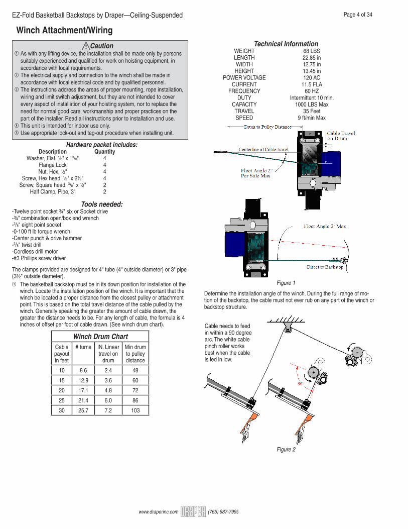
The clamps provided are designed for 4" tube (4" outside diameter) or 3" pipe (3½" outside diameter).1 The basketball backstop must be in its down position for installation of the winch. Locate the installation position of the winch. It is important that the winch be located a proper distance from the closest pulley or attachment point. This is based on the total travel distance of the cable pulled by the winch. Generally speaking the greater the amount of cable drawn, the greater the distance needs to be. For any length of cable, the formula is 4 inches of offset per foot of cable drawn. (See winch drum chart).
Caution1 As with any lifting device, the installation shall be made only by persons suitably experienced and qualified for work on hoisting equipment, in accordance with local requirements.2 The electrical supply and connection to the winch shall be made in accordance with local electrical code and by qualified personnel.3 The instructions address the areas of proper mounting, rope installation, wiring and limit switch adjustment, but they are not intended to cover every aspect of installation of your hoisting system, nor to replace the need for normal good care, workmanship and proper practices on the part of the installer. Read all instructions prior to installation and use.4 This unit is intended for indoor use only.5 Use appropriate lock-out and tag-out procedure when installing unit.
Determine the installation angle of the winch. During the full range of mo- tion of the backstop, the cable must not ever rub on any part of the winch or backstop structure.
Figure 1
Figure 2
Hardware packet includes: Description Quantity Washer, Flat, ½" x 13/8" 4 Flange Lock 4 Nut, Hex, ½" 4 Screw, Hex head, ½" x 2½" 4 Screw, Square head, 3/8" x ½" 2 Half Clamp, Pipe, 3" 2
Tools needed:-Twelve point socket ¾" six or Socket drive-¾" combination open/box end wrench-3/8" eight point socket-0-100 ft lb torque wrench-Center punch & drive hammer-3/8" twist drill-Cordless drill motor-#3 Phillips screw driver
Technical Information WEIGHT 68 LBS LENGTH 22.85 in WIDTH 12.75 in HEIGHT 13.45 in POWER VOLTAGE 120 AC CURRENT 11.5 FLA FREQUENCY 60 HZ DUTY Intermittent 10 min. CAPACITY 1000 LBS Max TRAVEL 35 Feet SPEED 9 ft/min Max
Winch Drum ChartCable payout in feet
# turns IN. Linear travel on
drum
Min drum to pulley distance
10 8.6 2.4 48
15 12.9 3.6 60
20 17.1 4.8 72
25 21.4 6.0 86
30 25.7 7.2 103
Cable needs to feedin within a 90 degreearc. The white cablepinch roller worksbest when the cableis fed in low.

EZ-Fold Basketball Backstops by Draper—Ceiling-Suspended Page 5 of 34
www.draperinc.com (765) 987-7999
2 Attach one half of each pipe clamp to the base plate of the winch as shown. This is so that you can place the winch on the mounting structure pipe and have the clamps handy for assembly.
3 Insert the second set of bolts and washers into clamps and base plate.
4 Position the winch and hand tighten the bolts so that the winch will remain in position on the pipe.5 Mark pipe for set screw hole. Use the 3/8" 8 point socket and drive handle to tighten the 3/8" square head set screw against the pipe enough to dent the paint on the pipe.6 Loosen the clamp bolts enough that the winch can be rotated and moved about 3" to one side.7 Use center punch to mark and indent the centers of where the set screw upset the paint on the mounting pipe. This is so that you can drill an index hole in the pipe to prevent rotation of the hoist.
8 Drill the pipe with the 3/8" drill so that the holes pierce completely into the interior of the pipe.
9 Re-position the winch clamps over the holes in the pipe and tighten the square head set screws into the holes in the pipe. Torque the set screws to 18 ft lbs.10 Tighten the four half inch hex bolts that hold the clamps to the base plate. Torque the nuts on the hex bolts to 35 ft lbs.
11 Connect winch to building or temporary power source.12 If necessary, route cable as shown on backstop drawings.13 Use only ¼" Galvanized Steel, 7 x 19 stranded wire Rope (per MILDTL- 83420 or Equivalent). Assure the cable set screws are loosened enough to allow the cable to insert fully into the drum. Insert cable into socket in drum, and push through until the end is exposed on the opposite side of the drum.
15 Wind a minimum of two safety wraps of cable on the drum.16 The cable must wind onto the drum following the grooves on the drum. It will only wind properly on the drum in one direction.
Figure 3
Figure 4
Figure 5
Figure 6
Figure 7
Figure 9
Figure 10
14 Torque both set screws to 7 ft lbs.
set screws
Figure 8

WARNING: Cable winding on drum poses a severe pinch hazard! Use extreme caution while installing cable. Do not guide cable onto drum with hands; use proper tools. Do not damage or nick the cable in the pro-cess of winding it onto the drum. Do not wear loose clothing, long hair, jewelry, etc. When installing cable on drum, ensure that the opposite end of the cable is free. Do not attach cable to backstop until the hoist unit is installed and the cable wound on the drum.(17) Attach far end of cable to the backstop. Leave 1"-2" of slack in cable.
(18) Lock out electrical power.WARNING: HIGH VOLTAGE! Setting the limit switches is a hazardous operation. To set the limit switches you must access the winch while the cable is installed. Lock out and tag the circuit breaker for this unit before adjusting the limit wheel settings. This prevents electric shock, and injury due to unexpected winch movement.(19) Set limit switches. Loosen the retaining screw and remove the limit Box Cover.
(20) Press the black index locking bar away from the down direction index wheel so it can rotate freely. Rotate the wheel until the switch “clicks” indicating that the switch is active.
(21) Unlock and restore electrical power. Twist the key switch in the down direc- tion to verify the down switch setting. The winch should not move.(22) Lock out electrical power and adjust the down direction wheel as necessary to obtain desired setting. The cable should have 1"-2" of slack in the down position.(23) Estimate the amount of cable drawn when the backstop travels from the deployed (down) position to the stowed (up). The number of feet of cable is roughly equivalent to the number of threads between the two index wheels.(24) Set the Up Direction index wheel so that the two wheels are the same number threads apart as the cable travel in feet.(25) Unlock and restore power.(26) Operate the winch to raise the backstop to its stowed position. Since each rotation of the drum is about 14.2 inches, the winch should stop short of desired stowage; the drum rotates at the same speed as the limit shaft.WARNING: Always directly observe the movement of the backstop when-ever operating, watching for mechanical interference!(27) Remember to appropriately lock and unlock the electrical power. Adjust the up direction limit switch until the backstop is set.(28) Place the cover on the limit box and secure the screw with a screwdriver.
EZ Backstop Winch by Draper Page 3 of 4
www.draperinc.com (765) 987-7999
CableThimble
CableClamp
AircraftCable
CableClamp Figure 10
Figure 11
Figure 12
Please Note: Key switch supplied only with 503285.
Wiring Diagram2¾”
13/8 ”
5/8 ”
3¼”
4½”
FRONT
BLUE(UP)
RED(DOWN)
7/16 ”
1 13/16 ”
TOP
G
W
X
Y
G
W
X
Y
Ground
L2 (Neutral)
L1 (Hot)
421
MotorUp to ¾ HP110 - 120 V/1/60Instant Reverse Dn Limit
Switch
WHITE
RED
BLK
Up LimitSwitch
Terminal Blockor ConnectorsBy Others
Factory Wiring
Wiring By ElectricianUse Minimum No. 12/3
BLUEBLACK
RED
Circuit Breaker Rating: 20 Amp.
Fused Circuit Rating: 20 Amp.
Full Load Amperage: 9.8 Amp
Recommended Minimum Wire Size
90' Maximum Run 12 AWG
91' to 140' Run 10 AWG
140' to 225' Run 8 AWG
Wire size recommendations based on ¾ HP Motor, 3% voltage drop, copper wire and are calculated
using standard wire size calculation methods
Size of wall masonry boxes required for single and key switches All Boxes: 2" (w) x 3 ¾" (h) x 2 ½" (d)

EZ-Fold Basketball Backstops by Draper—Ceiling-Suspended Page 7 of 34
www.draperinc.com (765) 987-7999
Winch Dimensions
4" 93/8"
Ø4" 1'6" +
125 /8"
5¾"
CableWind
Direction
1'11"
Manual Winch(Not recommended for use backstops above 28'-0".)
Warning: Winch shall be located so that backstops are in full view of operator, but in a position where operator is clear from potential injury if the backstop were to fall. Not to be used for lifting people or to lift anything over people without a safety lock or automatic fall arrest system in place.1 Find installation location according to project drawings2 Four 7/16" diameter holes are provided for mounting the winch. It will be necessary to remove winch cover during installation. Attachment hardware will vary based on field conditions A) To mount to 2 x 8 x 36" wooden wall pads - Locate winch at center of wood pad with the pad running vertically. Mark and drill 13/32" holes and attach using 3/8"-16 x 2½" carriage bolts and flange lock nuts. Anchor wooden wall pad per Draper recommendations and using hardware that is appropriate for wall construction and field conditions (see Fig. 1).
Figure 1
Caution1 As with any lifting device, the installation shall be made only by persons suit- ably experienced and qualified for work on hoisting equipment, in accordance with local requirements.2 While these instructions address the areas of proper mounting, and cable installation, they are not intended to cover every aspect of installation of your hoisting system nor to replace the need for normal good care, workmanship and proper practices on the part of the installer.3 Max. Safe Working Load shall be 1000 lbs./454 kg.4 Winch shall be located so that backstops are in full view of operator, but in a position where operator is clear from potential injury if the backstop were to fall.5 Not to be used for lifting people, or for lifting anything over people without a safety locking device or an automatic fall arrest system in place.6 Do not use height adjuster electric operator or other electric drills. Use hand crank or optional 503249 Portable Electric Winch Operator.
1½"
3"
9"
55/16"31/32"
3'0" 6"
1'3"
9"
3"
2x8 Wood Pad3/8"-16 FlangeLock Nut
3/8"-16 x 2½"Carriage Bolt
503286
B) To mount to plate or other steel brackets. – Winch is attached to steel plate or brackets using 3/8"-16 x 1¼" hex head bolts and flange lock nuts. Attach to column or other surface as shown on project drawings (see Fig. 2).
3 Turn winch handle so that cable attachment point (on gear box side of drum) is visible. Insert ¼" diameter 7 x 19 aircraft cable into hole until end is exposed on opposite side of Drum. Tighten both set screws against cable. Then wrap between one and 1½ wraps cable drum to determine the full down position (sse Fig. 3).
3/8"-16 x 1¼" Boltwith Washer andFlange Lock Nut
Vertical Column
C016.054SA
503286
C002.958
Tapered Column
C421.00xMA Flangethickness specific
C415.06xMA FlangeWidth Specific
C151.024
503286
4" OD x 11 Gage TubeC415.002MA
3/8"-16 x 1¼" Boltwith Washer andFlange Lock Nut
Figure 2
Vertical Column
Tapered Column
4 Draper suggest that the cable be marked with a piece of tape or bright paint to indicate when backstop is in full stored position to prevent users from over- folding and potentially damaging backstop or structure to which the backstop is mounted.5 After installation is complete re-attach winch cover.
Figure 3
EZ-Fold Basketball Backstops by Draper—Ceiling-Suspended Page 8 of 34
www.draperinc.com (765) 987-7999
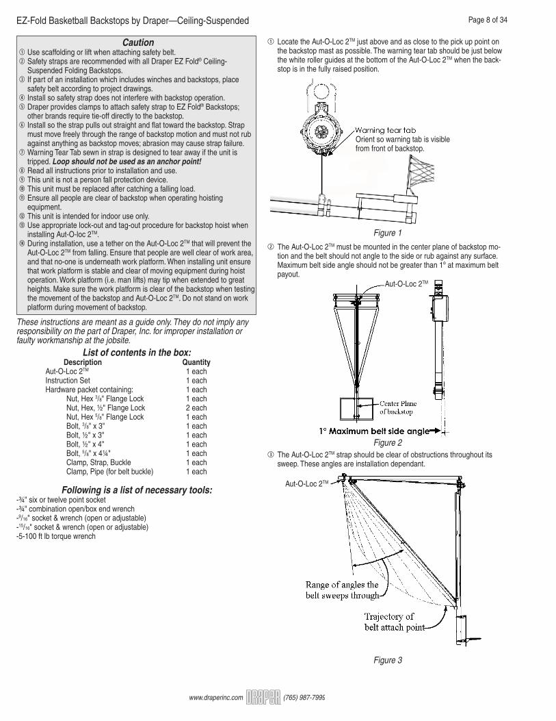
Caution1 Use scaffolding or lift when attaching safety belt.2 Safety straps are recommended with all Draper EZ Fold® Ceiling- Suspended Folding Backstops.3 If part of an installation which includes winches and backstops, place safety belt according to project drawings.4 Install so safety strap does not interfere with backstop operation.5 Draper provides clamps to attach safety strap to EZ Fold® Backstops; other brands require tie-off directly to the backstop.6 Install so the strap pulls out straight and flat toward the backstop. Strap must move freely through the range of backstop motion and must not rub against anything as backstop moves; abrasion may cause strap failure.7 Warning Tear Tab sewn in strap is designed to tear away if the unit is tripped. Loop should not be used as an anchor point!8 Read all instructions prior to installation and use.9 This unit is not a person fall protection device.10 This unit must be replaced after catching a falling load.11 Ensure all people are clear of backstop when operating hoisting equipment.12 This unit is intended for indoor use only.13 Use appropriate lock-out and tag-out procedure for backstop hoist when installing Aut-O-loc 2TM.14 During installation, use a tether on the Aut-O-Loc 2TM that will prevent the Aut-O-Loc 2TM from falling. Ensure that people are well clear of work area, and that no-one is underneath work platform. When installing unit ensure that work platform is stable and clear of moving equipment during hoist operation. Work platform (i.e. man lifts) may tip when extended to great heights. Make sure the work platform is clear of the backstop when testing the movement of the backstop and Aut-O-Loc 2TM. Do not stand on work platform during movement of backstop.
These instructions are meant as a guide only. They do not imply any responsibility on the part of Draper, Inc. for improper installation or faulty workmanship at the jobsite.
Figure 1
List of contents in the box: Description Quantity Aut-O-Loc 2TM 1 each Instruction Set 1 each Hardware packet containing: 1 each Nut, Hex 3/8" Flange Lock 1 each Nut, Hex, ½" Flange Lock 2 each Nut, Hex 5/8" Flange Lock 1 each Bolt, 3/8" x 3" 1 each Bolt, ½" x 3" 1 each Bolt, ½" x 4" 1 each Bolt, 5/8" x 4¼" 1 each Clamp, Strap, Buckle 1 each Clamp, Pipe (for belt buckle) 1 each
Following is a list of necessary tools:-¾" six or twelve point socket-¾" combination open/box end wrench-9/16" socket & wrench (open or adjustable)-15/16" socket & wrench (open or adjustable)-5-100 ft lb torque wrench
1 Locate the Aut-O-Loc 2TM just above and as close to the pick up point on the backstop mast as possible. The warning tear tab should be just below the white roller guides at the bottom of the Aut-O-Loc 2TM when the back- stop is in the fully raised position.
2 The Aut-O-Loc 2TM must be mounted in the center plane of backstop mo- tion and the belt should not angle to the side or rub against any surface. Maximum belt side angle should not be greater than 1º at maximum belt payout.
Figure 23 The Aut-O-Loc 2TM strap should be clear of obstructions throughout its sweep. These angles are installation dependant.
Aut-O-Loc 2TM
Aut-O-Loc 2TM
Orient so warning tab is visible from front of backstop.
Figure 3

EZ-Fold Basketball Backstops by Draper—Ceiling-Suspended Page 9 of 34
www.draperinc.com (765) 987-7999
4 Insert ½" x 3" bolt in top clamp hole and finger tighten into opposite half clamp using ½" lock washer and nut. Place clamp over mounting pipe. Lift Aut-O-Loc 2TM unit up to clamp, insert 5/8" x 4¼" bolt through bottom hole in both clamp halves and Aut-O-Loc 2TM unit and finger tighten using 5/8" lock washer and nut. If attaching to 3½" OD tube, insert ½" x 4" bolt in middle clamp hole and finger tighten using nut and lock washer. Position the Aut-O-Loc 2TM and hand tighten all bolts so that the Aut-O-Loc 2TM will remain in position on the pipe.
Figure 45 Stretch belt out and attach to mast. Use following steps to properly install belt clamp.
Figure 5
Hoisting Cableattachment point
Brace Lower Pivot
Safety Strapbasket
6 Wrap end around mast attach point. Place sewn tail of belt loop on the outside of the loop. Insert bolt through the clamp and clamp tube and tighten Nyloc nut on opposite side.
Figure 6
7 Tighten the top and middle ½" clamp nuts to a torque of 35 ft lbs.8 Tighten the bottom 5/8" clamp nut to a torque of 45 ft lbs.
Figure 7
9 Tighten the 5/8" bolt so the pipe clamp is tight against the surface of the cast housing and the lock washer is compressed.
10 Check belt clamp assembly, tighten 3/8" nut to 22 ft lbs torque. Run back- board through a complete up and down cycle to assure unit is working properly.
* ½" x 4" bolt only required when attacking to 3½" OD tube.

EZ-Fold Basketball Backstops by Draper—Ceiling-Suspended Page 10 of 34
www.draperinc.com (765) 987-7999
Joint Pins(Not on all models)
Attach pads using appropriate screws (three sizes provided). Make sure all washers and lock washers are used, to avoid loosening. If needed, trim for goal clearance. (Some backboard and goal com- binations will require extra trimming of pads to provide for goal clearance.)
IF PROVIDED: Use joint pins in pad half ends to eliminate sagging.
Drill holes (minimum 1/4", maximum 5/16") at marked locations. Drill completely through all framework structure.
503253/503264 (glue-on:) Hold each half of pad in place and mark pads for trimming around support structure (if required). When required trimming is complete, apply coat of glue to inside of padding. Allow glue to dry until it becomes tacky (less than a minute). While glue is drying on padding, apply a coat to the backboard. Attach padding to backboard.5032XX (bolt-on) Hold each half of pad in place and mark pads for trimming around support structure (if required). Trim pads. Hold pads in proper position and mark holes for drilling into board framework (8 holes per backboard). Make sure the holes closest to the center of the backboard (under the rim) are positioned so that the pads join fully in the middle.
CAUTION: On all glass or acrylic backboards, use holes near-est the rear of the backboard to avoid possible damage.
PaddingJoint Pins
Backboard padding.Please Note: This step can be completed at any point during instal-lation; the most convenient time is during bank/goal assembly, prior to bank attachment.
Nearest toback for glassand acrylicbackboards
Touch up any scratches caused during installation or shipping. Remove tools and scrap from jobsite. Ensure all backstops are level and in accordance with measure- ments on project drawings. Tighten all bolts, and ensure that backstops are ready for use. Verify that all backstops are functioning properly. Set all limit switches on electric winches. Coat Inner Tubes of Height Adjusters with petroleum jelly. Make sure all chalk lines are wiped from floor. Dispose of boxes and packing materials. Explain proper winch and backstop maintenance and operation to the customer.
Before leaving the jobsite:NOTE: If you encounter any difficulties installing or servicing your EZ-Fold® Ceiling-Suspended or Wall-Mounted Backstop by Draper, Inc., contact your dealer or Draper, Inc. at (765) 987-7999; or fax (765) 987-7142.
If you misplace a portion of these instructions, they are also avail-able on our Website, www.draperinc.com.
CAUTIONGlue used to attach Draper backboard padding is extremely flammable. Keep away from heat and flame. Keep out of reach of children. Avoid prolonged exposure to fumes: Use in a well-ventilated area.
EZ-Fold Basketball Backstops by Draper—Ceiling-Suspended Page 11 of 34
www.draperinc.com (765) 987-7999
EZ-Fold® Backstops by DRAPERInspection/Maintenance List
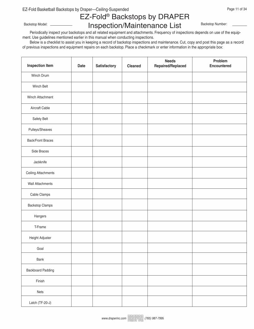
Periodically inspect your backstops and all related equipment and attachments. Frequency of inspections depends on use of the equip-ment. Use guidelines mentioned earlier in this manual when conducting inspections. Below is a checklist to assist you in keeping a record of backstop inspections and maintenance. Cut, copy and post this page as a record of previous inspections and equipment repairs on each backstop. Place a checkmark or enter information in the appropriate box:
Inspection Item
Winch Drum
Winch Belt
Winch Attachment
Aircraft Cable
Safety Belt
Pulleys/Sheaves
Back/Front Braces
Side Braces
Jackknife
Ceiling Attachments
Wall Attachments
Cable Clamps
Backstop Clamps
Hangers
T-Frame
Height Adjuster
Goal
Bank
Backboard Padding
Finish
Nets
Latch (TF-20-J)
Date Satisfactory CleanedNeeds
Repaired/ReplacedProblem
Encountered
Backstop Model: Backstop Number:

EZ-Fold Basketball Backstops by Draper—Ceiling-Suspended Page 12 of 34
www.draperinc.com (765) 987-7999
1 Mark off all measurements on floor using blue chalk line. (Measurements are included on project drawings.)2 Project chalk lines from the floor to the roof members using plumb bob or laser plumb pointer.
CAUTION: All measurements indicate center of clamp. Don’t forget to add or subtract distance to clamp edges when placing clamps.3 Attach clamp assemblies to roof structure (use numbers on project draw- ings to cross reference figures below). See Fig. G-1 and Fig. G-2, page 4, for tips on beam and tube mounts.Please Note: Make sure all bolt and screw heads are toward the floor (threads pointing up).4 Place superstructure tubing into clamp assemblies, insert cap screws, and start nuts.Please Note: All superstructure must be plumb and level before attaching T-Frame.5 Tighten with impact tool. All Draper Gymnasium Equipment is supplied with Grade 5 hardware. Clamps are designed to be installed with the nuts and bolts “tight.” Draper would consider tight to be torques between 40 ft-lbs and 60 ft-lbs.
Superstructure (Truss) Attachment
Please Note: Before attachment, hold hanger in place and mark hole locations on Z-Purlin. Drill 9/16" holes.
1/2"-13 x 21/2" Carriage Bolt,1/2" FT Washer, 1/2" Lock Washer,1/2" Flange Lock Nut (4)
4" Tubing
00324" x 2"H.C.
1/2"-13 x 2 1/2"
Cap Screw,Flange Lock Nut (2)
A0325Wall Mounted Tube Hanger
A0325
Wood Wall Pad
Z-Purlin
0322
1/2"-13 x 1 3/4"Cap Screw,Flange Lock Nut (2)
A0100
4" Tubing
0032
A0100 or A0150Z-Purlin Hanger
1/2"-13 x 2
1/2"Cap Screw,Flange Lock Nut (2)
1
1/2"
0322Backing Plate
1/4"
3"3/4"
2
1/4"
4 1 /2
"3
3 /4"
3 /4"
Standard Joist Clamp
Caution: Draper, Inc., is not responsible for roof strength. Do not install truss if roof is not strong enough to bear stress loads required for backstop.
4" to 14"Structure
1-1/8"
1/2"-13Threaded
Rod
C018.0881/2"-13Flange
Lock Nut
4" O.D.11 Gage
TubePowder Coated
C002.6951/4" Thick Steel
BracketPowder coated
C019.0691/2"-13 x 4" Dia.
U-BoltZinc Plated
7-1/16"
5-3/4"
1-3/
4"Sl
ot3/
8"
2-3/
4"
Split "A" Clamp
1/2" FlatWasher
1/2" FlatWasher
4" to 14"Structure
1-1/8"
1/2"-13Threaded
Rod
C018.0881/2"-13Flange
Lock Nut
4" O.D.11 Gage
TubePowder Coated
C002.6951/4" Thick Steel
BracketPowder coated
C019.0691/2"-13 x 4" Dia.
U-BoltZinc Plated
7-1/16"
5-3/4"
1-3/
4"Sl
ot3/
8"
2-3/
4"
Split "A" Clamp
1/2" FlatWasher
1/2" FlatWasher
4" O.D. 11-gageTube
Joist
Flat Washer,1.375" OD
Flange LockHex Nut1/2"-13Grade F Zinc
AdjustableSplit-A Clamp
C415.030MA X = 31/2" -51/8"C415.031MA X = 31/2" -61/8"C415.032MA X = 31/2" -71/8"
1/2"-13 x 2"Cap Screw,Flange Lock
Nut (4)
4" x 2"Half
Clamp (2)
X
C077.031 (2)½"-13 Th. Rod
½"-13 x 1½"Carriage Bolt
Adjustable Split-A Clamp Flange TH: Part No. ¼" C415.001WA 3/8" C415.002WA ½" C415.003WA 5/8" C415.004WA ¾" C415.005WA 7/8" C415.006WA 1" C415.007WA
C002.695
Beamor Joist
4" Tubing
½"-13 Threaded Rod ½"-13 x 4"Dia. U-Bolt
FlangeLock
Nut (2)
F-Shaped BracketSee Chart
F-Shaped Bracket
1/4" 15/8"
21 /2"

EZ-Fold Basketball Backstops by Draper—Ceiling-Suspended Page 13 of 34
www.draperinc.com (765) 987-7999
*Cap Screws used with Spacer Flats:Up through 3/8" = 1 3/4" C.S.3/8"-3/4"= 2" C.S.3/4"-1 1/4" = 2 1/2" C.S.
A0340Perpendicular Beam Mounted Tube Hanger
Beamor Joist
Cap Screw,*1/2" Washer,Flange Lock Nut (2)Spacer
Flat (2)4" Tubing
4" x 4"Half
Clamp
A0340 1/2"-13 x 2"Cap Screw, Flange LockNut (4)
6"
Beamor Joist
SpacerFlat (2)
Cap Screw*,1/2" Washer,Flange Lock Nut (2)6"
A04674" x 4"Half
Clamp4" Tubing
A0467Parallel Beam Mounted Tube Hanger
1/2"-13 x 2"Cap Screw,Flange Lock
Nut (4)
C421.001MA - 1/4"C421.002MA - 3/8"C421.003MA - 1/2"C421.004MA - 5/8"C421.005MA - 3/4"C421.006MA - 7/8"C421.007MA - 1"
See Chart
Spacer Flat
3"
6"
Beam width + 4" (std)
1/2"-13 Threaded Rod
1/2"-13 FlangeLock Nut
1/2" Threaded Rod Assembly
*See Chart*See Chart
*See Chart
A0476Tube Mounted Standoff Hanger
A0726or
A0733
A04765/8"-11 x 2"Cap Screw,
Lock Washer,Hex Nut
1/2"-13 x2" Cap
Screw (4),Flange
Lock Nut
Beamor Joist
4" Tubing 4" x 4"Half Clamp
Standoff Attachment1 Attach hangers to superstructure.2 Install standoff. (Standoff hangers and pieces vary according to installation. Cross reference diagrams with project drawings using part numbers.)Please Note: Make sure all bolt and screw heads are toward the floor (threads pointing up).
A0739 and A0740Beam Mounted Standoff Hanger
A0740
A0739
Beam Plate
3 1/2
"
3 1/2
"
6"Beamor Joist
SpacerFlat (2)
SpacerFlat (2)
6" Beamor Joist
Please Note: See A0726 & A0733 for typ. use.
A02524" Back-to-Back Half Clamp
4" Tubing
1/2"-13 x 2
1/2"Cap Screw,Flange Lock Nut (8)
4" Tubing
00304" x 4"
H.C. (2)A0252
41/2"
4" O.D. Tubing 4" x 2" Half Clamp
Beamor Joist
SpacerFlat
6" ½"-13 Grade 5 CapScrew and Flange Nutw/USS Flat Washer.Length as required forthickness of flange.
½"-13 x 2" Grade 5Cap Screw andFlange Nut
A0357
C415.023MA4" Back-to-Back Half Clamp
Mounting Plates¼"
(See
Cha
rt)
3"¾
" 6"PartNo.
C010.190C010.191C010.192C010.193
PlateWidth11"14"18"22"
BeamWidth3"-7"
7"-10"10"-14"14" - 19"

EZ-Fold Basketball Backstops by Draper—Ceiling-Suspended Page 14 of 34
www.draperinc.com (765) 987-7999
A0341Beam Mounted Standoff W/Perpendicular Clamp
1/2"-13 x 2"Cap Screw,Flange Lock Nut (4)
6"Beamor Joist
SpacerFlat (2)
4" Tubing
4" x 4"Half Clamp A0341
Cap Screw,*1/2" Washer,Flange LockNut (4)
A0475Beam Mounted Standoff
SpacerFlat (2)
Beam or Joist
0038
4" Tubing
Cap Screw,*1/2" Washer,Flange LockNut (4)
A04751/2"-13 x 2"
Cap Screw, Flange Lock
Nut (8)
4" x 4"Back-to-BackClamp
SafetyBolt
4" x 4"Half Clamp (2)
6"
41/2"
A0474Beam Mounted Standoff W/Parallel Clamp
SpacerFlat (2)
Beamor Joist
4" Tubing 4" x 4"Half Clamp
A0474
Cap Screw,*1/2" Washer,Flange LockNut (4)
1/2"-13 x 2"Cap Screw, Flange Lock
Nut (4)
6"4" Tubing
A0734
A0734Tube Mounted Standoff W/Clamp
0038
4" Tubing
Beam or Joist
1/2"-13 x 2"Cap Screw,Flange LockNut (4)
1/2"-13 x 2"Cap Screw,
Flange LockNut (8)
4" x 4" Backto Back Clamp
SafetyBolt
4" x 4" HalfClamp (2)
41/2"
4" x 4"Half Clamp
A0733Beam Mounted Standoff W/Lug
SafetyBolt
4" x 4"Half
Clamp (2)
4" back-to-Back Half Clamp
0038
4" Tubing
A0739or
A0740
SpacerFlat (2)
Beamor Joist
A0733
1/2"-13 x 2"Cap Screw,
Flange Lock Nut (8)
Cap Screw,*1/2" Washer,Flange LockNut (4)
5/8"-11 x 2"Cap Screw,Lock Washer,Hex Nut
6"
41/2"
A0726Beam Mounted Standoff W/Clamp & Lug
4" x 4" Half Clamp
4" Tubing
Beam or Joist
5/8"-11 x 2"Cap Screw,Lock Washer,Hex Nut
6"SpacerFlat (2)
A0739or
A0740
1/2"-13 x 2"Cap Screw,
Flange LockNut (4)
Cap Screw*,1/2" Washer,Flange LockNut (4)
A0726
A0272
A0273 A0274 A0275
33/4"O.D. 13 Gauge tubing
1/2"-13 X 5" Hex Bolt w/Nylon Nut(Typical two places)
Note: The A0272 must be fielddrilled for the safety bolts.
31/2"O.D. 11 Gauge tubing 1/2"-13 X 21/2" Flange LockBolt W/Nut (Typical 4 places)
0030
4"OD Tubing
11/2"
3"
Beam Plate Sized as needed
0030
Upper/Outer Tube is A0273, A0274 orA0275 depending on project conditions
Adjustable Stand-Offs

EZ-Fold Basketball Backstops by Draper—Ceiling-Suspended Page 15 of 34
www.draperinc.com (765) 987-7999
Please Note: Drawings will show locations of wall pads. Before drill-ing, make sure there are no obstructions or electrical wiring where you will be drilling. Spread plastic throws on inside floor before drilling.1 Mark wall attachment locations on 0037 Wood Wall Pads (see figure at right). These may be adjusted to meet field conditions. (If thru-bolts are present, lay out holes to match bolt locations.) Drill four 9/16" diameter holes.2 Position part to be attached to wood pad on center line. Mark hole locations, and drill required number of 7/16" holes.3 Turn wood pad to unfinished side, countersink 7/16" holes so carriage bolt heads will be flush with wood pad (1 3/8" diameter x 3/8" deep).4 Place wood pad against wall and mark wall where 9/16" holes are drilled in wood pad.5 Drill holes in wall as required.6 Install 1/2"-13 x 2 1/2" carriage bolts with 1/2" flat washers in 9/16" holes from back side of pad.7 Place wood pad on wall and attach with type of wall bolt appropri- ate for field conditions.8 Tighten wall bolts with hand wrench.
Please Note: Although not necessary, flat washers may be used in countersunk holes to ensure all mounting bolts coming through the wall pad extend the same distance from the surface of the wood wall pad.
Wood Wall Pad Installation
2" x 8" Wood Wall Pad
Wood Wall Pad Mounting Options (Typ.)
2
1/2"Min.
1/2" ToggleBolt
Toggle Bolt
1/2" x 4"Lag Screw
1/2" FlatWasher
1/2" LockWasher1/2" Lag
Shield Use only in joint of block,brick, or concrete wall.
Lag Screw and Shield
2
1/2"Min.
1/2" MachineBolt
Pre-set byGeneral Contractor
Set-in Bolt
2
1/2"Min.
1/2" MachineBolt
Thru-Bolt
Wall Attachment
* Drill holes according to attachment hardware used. Attach-ment hardware, number of holes and hole placement to be determined by the installer to meet building conditions.
Caution: Draper, Inc., is not responsible for wall strength. Do not install wall pads if wall is not strong enough to bear stress loads required for backstop. Attachment method to be determined by project architect/engineer. Attachment hardware provided by others.
Please Note: Attachment method to be determined by project architect/engineer. Attachment hardware provided by others.
CL
3"
1 1/2" (typ.)
1'6"
7 1/2"
9/16"Hole (4)
3'-0
"
9"
3"
9"

EZ-Fold Basketball Backstops by Draper—Ceiling-Suspended Page 16 of 34
www.draperinc.com (765) 987-7999
Upper Back Brace and Jackknife Hangers/Attachments.Please Note: Install Jackknife Hangers so that Cable Sheaves are in line with the center of the Winch Cable Spool.Perpendicular and parallel are used to describe the Hanger’s posi-tion in relation to the backboard.
A0451Parallel Upper Jackknife Hanger
Assemble sheave in fronthole when winch is in front
Assemble sheave in middlehole when winch is in rear
1/2"-13 x 2 1/2"
Cap Screw, NylonStop Nut - Finished
Full (2)
A04511/4" Aircraft
Cable
1/2"-13 x 2 1/2"
Cap Screw, FlangeLock Nut (4)
4" Tubing
0030
Jackknife
To Winch
A03338" Perpendicular Upper Jackknife Hanger
Jackknife
A0333
4" Tubing
0030
1/2"-13 x 2
1/2" CapScrew, Flange Lock Nut (4)
1/2"-13 x 2
1/2"Cap Screw, Nylon
Stop Nut -Finished Full
A03328" Parallel Upper Jackknife Hanger
Jackknife
A0332
1/2"-13 x 2
1/2"Cap Screw, Nylon
Stop Nut -Finished Full
1/2"-13 2
1/2" CapScrew, FlangeLock Nut (4)
4" Tubing
0030
A07478" Beam Mounted Parallel Upper Jackknife Hanger
Jackknife
A0747
SpacerFlat (2)
Beamor Joist 6"
Cap Screw*,Flange Lock Nut (4)
1/2"-13 x 2
1/2"Cap Screw, NylonStop Nut-Finished FullA0748
8" Beam Mounted Perpendicular Upper Jackknife Hanger
Jackknife
A0748
6"Beam
or Joist SpacerFlat (2)
Cap Screw*,Flange Lock
Nut (4)
1/2"-13 x 2
1/2"Cap Screw, Nylon
Stop Nut -Finished Full
A0452Perpendicular Upper Jackknife Hanger
Assemble sheave in fronthole when winch is in front.
Assemble sheave in middlehole when winch is in rear.
1/2"-13 x 2
1/2"Cap Screw, NylonStop Nut -Finished full (2)
A04521/4" Aircraft Cable
Jackknife
4" Tubing0030
1/2"-13 x 2
1/2"Cap Screw, FlangeLock Nut (4)
To Winch
C418.008MAParallel Upper Jackknife Hanger
C418.009MAPerpendicular Upper Jackknife Hanger
C418.028MATF-20J Parallel Upper Jackknife Hanger
C418.029MATF-20J Perpendicular Upper Jackknife Hanger
To Winch
Jackknife
¼" Cable
C418.016MA - 11" PlateC418.017MA - 14" PlateC418.018MA - 18" PlateC418.019MA - 22" Plate
½"-13 HexHead Cap Screw
½" Flat Washer
Flange Lock NutSpacer FlatJoist
½"-13 NylonStop Nut
½"-13 X 2½" HexHead Cap Screw
Joist
Beam Mounted Perpendicular Upper Jackknife Hanger
Beam Mounted Parallel Upper Jackknife Hanger
To Winch
Jackknife
¼" Cable
C418.020MA - 11" PlateC418.021MA - 14" PlateC418.022MA - 18" PlateC418.023MA - 22" Plate
½"-13 HexHead Cap Screw
½" FlatWasher
Flange Lock NutSpacer FlatJoist
½"-13 NylonStop Nut
½"-13 X 2½" HexHead Cap Screw
Joist
C418.039WA-11" PlateC418.040WA-14" PlateC418.041WA-18" PlateC418.042WA-22" Plate
C418.035WA-11" PlateC418.036WA-14" PlateC418.037WA-18" PlateC418.038WA-22" Plate

EZ-Fold Basketball Backstops by Draper—Ceiling-Suspended Page 17 of 34
www.draperinc.com (765) 987-7999
A031712" Parallel Upper Jackknife Hanger
Jackknife
A0317
4" Tubing
00301/2"-13 x
2
1/2" CapScrew,
Flange LockNut (4)
1/2"-13 x 2
1/2"Cap Screw, Nylon
Stop Nut -Finished Full
A031812" Perpendicular Upper Jackknife Hanger
Jackknife
A0318
0030
1/2"-13 x2
1/2" Cap Screw, Flange Lock Nut (4)
1/2"-13 x 2
1/2"Cap Screw, Nylon
Stop Nut -Finished Full
A03348" Parallel Upper Jackknife Hanger with Sheave
Jackknife
A0334
4" Tubing
0030
1/2"-13 x 2
1/2"Cap Screw, Flange Lock Nut (4)
1/2"-13 x 2
1/2"Cap Screw, Nylon
Stop Nut -Finished Full
A0302Perpendicular Rigid Guide
0037 Wood Wall Pad
1/2"-13 x 2
1/2" Carriage Bolt,1/2" Washer, 1/2" FT Washer,& Flange Lock Nut (4)
A0302
Jackknife
1/2"-13 x 2
1/2"Cap Screw, Nylon
Stop Nut -Finished Full
A0319Perpendicular Kickbrace Hanger
0038
4" Tubing
1/2"-13 x 2"Cap Screw, Flange Lock Nut
SafetyBolt
A0475or
A0733
A0319
1/2"-13 x 2
1/2"Cap Screw,Flange LockNut (4)
1
1/2" Kickbraceor Backbrace
41/2"
A0252
A0477Parallel Kickbrace Hanger
4" Tubing
0038 1/2"-13 x 2"Cap Screw,
Flange Lock Nut
A0477
SafetyBolt
A0475or
A0733
1/2"-13 x 2
1/2"Cap Screw,Flange Lock Nut (4)
1
1/2" Kickbraceor Backbrace
41/2"
A0252
A0737Beam Mounted Kickbrace Hanger - Perpendicular
1
1/2" Kickbraceor Backbrace
1/2"-13 x 2"Cap Screw,Flange Lock Nut
SpacerFlat (2) Beam
or Joist 6"
A0737Cap Screw,*1/2" Washer,Flange Lock
Nut (4)
A0738Beam Mounted Kickbrace Hanger - Parallel
1
1/2" Kickbraceor Backbrace
1/2"-13 x 2"Cap Screw, Flange Lock Nut
Cap Screw,*1/2" Washer,
Flange Lock Nut (4)
A0738
Beamor Joist
SpacerFlat (2) 6"

EZ-Fold Basketball Backstops by Draper—Ceiling-Suspended Page 18 of 34
www.draperinc.com (765) 987-7999
Backstop Attachment(To be completed AFTER Backstop Assembly—See assembly details beginning on page 8)
1 Attach Backstop Hangers to backstop. (Hanger types vary accord- ing to installation. Cross reference diagrams with project drawings using part numbers.)
Please Note: Make sure to place the bottom of the main stem on a dolly, or casters, to keep from damaging the floor during hoisting of Backstop.
2 Connect cable to cable clamp on Main Stem.
3 Carefully hoist Backstop into position.
CAUTION: Use extreme care when hoisting backstop. Hoisting too quickly, or having the cable too far down on the stem, can cause the frame to bounce or swing.
4 Attach Backstop to Superstructure. Please Note: Make sure all bolt and screw heads are toward the floor (threads pointing up).
5 Tighten screws and bolts with impact wrench.
6 Attach Back Brace, Kick Brace and/or Jackknife to backstop.
7 For folding backstops, attach cable and safety belt to proper con- nections. Raise and lower backstop to check operation.
Please Note: When marking roof structure or truss for Backstop Hanger placement, remember to account for offset distances (center to edge of clamp).
½" - 13 x 2"Cap Screw w/Flange Lock Nut 4" O.D. Tube
4" x 4"Half Clamp
T-FramePin(SteelShaft)
X
½" - 13 x 2"Cap Screw w/Flange Lock Nut
4" O.D. Tube4" x 4"Half Clamp
T-Frame
Pin(SteelShaft)
X
Assembly Number X C407.010MA 10" C407.011MA 12" C407.012MA 14" C407.013MA 16"
Note: Height is adjustable + 1"
Assembly Number X C407.001MA 10" C407.002MA 12" C407.003MA 14" C407.004MA 16"
Note: Height is adjustable + 1"
Parallel T-Frame Hangers
C407.002 MA (iso view)After backstop is plumb and level, tighten both carriage bolts to lock hanger length.
After backstop is plumb and level, tighten both carriage bolts to lock hanger length.
Perpendicular T-Frame Hangers

EZ-Fold Basketball Backstops by Draper—Ceiling-Suspended Page 19 of 34
www.draperinc.com (765) 987-7999
1 Bolt together T-Frame (for bolted frames) and attach Frame Hangers.Please Note: For Welded Frames, go to step 2.
Ceiling Suspended Backstop Assembly The following instructions are for all Draper EZ-Fold® Ceiling-Suspended Backstops. Diagrams of completed backstops, including guidelines on clamp placement, can be found immediately following this section. Skip steps that do not pertain to your backstop model. Scale project drawings will indicate locations of hangers, clamps, and braces. Follow your project drawing from top to bottom, assembling as you go, using this manual for assembly details. Tips on specific models are included with diagrams of completed backstops at the end of this section.
Webbing/Main Stem and Side Braces
Please Note: For TBS-26-B, Webbing is attached to Back or Front Brace.
Please Note: For TBS-26-B, attach Main Stem to Top-of-T according to project drawings. For all other models, attach Main Stem centered on Top-of-T. Please Note: TBS-26-B does not have Side Braces.
Side Braces/Main Stem
Please Note: The TBS-26-B has no Side Braces, only a Back or Front Brace and Jackknife.
SideBrace
Webbing
Circle Clamp(0299 for TBS-26-B,0035 for all others)
0033 6" x 2" Half Clamp (2),1/2"-13 x 21/2" Cap Screws (2),
Flange Lock Nuts (2)
1/2"-13 x 2"Cap Screw,
Flange Lock Nut
MainStem
MainStem
SideBraces
6" x 2"Half Clamp (2)
1/2"-13 x 2 1/2"
Cap Screw,Flange Lock Nut
ASSEMBLY NOTE: When assembling T-Frame, rest the Top-of-T on two overturned five gallon buckets; place the bottom of the main stem on a four-wheeled cart or casters. This will allow for easier assembly and hoisting of the backstop.
Please Note: All nuts and bolts used on the backstop frame require a 3/4" wrench or socket; height adjuster nuts and bolts require a 9/16" wrench or socket.
Top-of-T/Main Stem
Topof T
MainStem
0031 4" x 6"Half Clamp,1/2"-13 x 2
1/2"Cap Screws (4),Flange LockNuts (4)
Top-of-T/Side Braces/Hangers(Back or Front Brace for TBS-26-B)
Top-of-T
SideBrace
T-FrameHanger
4" x 2"Circle Clamp,½"-13 x 2" Cap Screw,Flange Lock Nut
CotterPin

EZ-Fold Basketball Backstops by Draper—Ceiling-Suspended Page 20 of 34
www.draperinc.com (765) 987-7999
2 Fasten Cable Pull Clamps, Safety Belt Clamp, and Lower Jackknife, Lower Back Brace, Kick Brace and/or A-Frame Hangers to Main Stem.
C413.001MA Cable Pull Clamp
Please Note: See project drawings for location on Main Stem. Make sure Chain Link faces direction of fold. Lightly tap Cable Thimble into place.
C418.001MA Lower Jackknife Hanger (all folding models EXCEPT TF-20J/J-B and TBS-26-B)
A0552 Safety Belt Clamp
Please Note: A0552 mounts outside Jackknife Hanger using the same Cap Screws that are used to fasten the Jackknife Hanger in place.
A0551 Safety Belt Clamp for TBS-26-B(top view)
Please Note: Mount A0551 using a 6" x 2" Half Clamp, two 1/2"-13 x 2" Cap Screws, and Flange Lock Nuts. Clamp should be on same side of backstop as Jackknife.
C418.002MA Lower Jackknife Hanger for TBS-26
Please Note: LH swing is shown. Sheave may need to be moved for RH swing.
1" OD x 2½" long pipe
2¼" disc welded to pipe
A0349 Jackknife Hanger for TF-20J/J-B,Back or Front Brace Hanger for TBS-26-B
and TS-21/21-BPlease Note: To determine distance of Lower Jackknife and Back (or Front) Brace Hangers from the top of the T-Frame, use this formula: (Middle-of-Stem to Upper Jackknife or Brace Hanger Hole Center) + (Middle of Stem to Face-of-Bank).
MainStem
1/2"-13 x 2
1/2"Cap Screws (2),
1/2"-13 FlangeLock Nuts (2)
0033 6" x 2" Half Clamp,A0349 Jackknife Hanger
Jackknife
C418.001MAJackknifeHanger
Safety BeltAnchor
SafetyBelt
1" OD x 2½" long pipe,2¼" disc welded to pipe
6" x 2"Half
Clamp
½" - 13 x 2"Cap Screws w/Flange Lock Nuts
C413.001MACable Thimble
¼" Cable
6" x 4"Half
Clamp
½" - 13 x 2½"Cap Screws w/Nylon Lock Nuts
C418.001MA Cable Sheave
Jackknife
½" - 13 x 2"Cap Screwsw/Flange Lock Nuts
6" x 4"HalfClamp
½" - 13 x 2½"Cap Screws w/Nylon Lock Nuts
C418.002MA
Jackknife
½" - 13 x 2"Cap Screws w/
Flange Lock Nuts
Front of
Backstop
LHSwing
Cable Sheave

EZ-Fold Basketball Backstops by Draper—Ceiling-Suspended Page 21 of 34
www.draperinc.com (765) 987-7999
A0554 Safety Belt Clamp (top view)
Please Note: Mount A0554 using a 6" x 2" Half Clamp, two 1/2"-13 x 2" Cap Screws, and Flange Lock Nuts. Place in direction of fold. Back Brace attachment for TS-22/22-B
3 Install Weight and Upper Stem Cable Sheave (TF-20J/J-B only).
Please Note: Install weight by threading cable down through Main Stem and attaching to weight with Cable Clamp. Then, pull weight up into Main Stem.
4 Assemble and attach Latch Assembly (TF-20J/J-B only).
Please Note: Center Latch in slot on Stem when Latch is in hori-zontal position. Make sure weight is ABOVE latch.
TF-20J Latch Assembly
MainStem
A0085Stem Weight
1/8" AircraftCable
1/8" CableClamp
Cable Sheave,1/2"-13 x 2"Cap Screw,Nylon Lock Nut
SafetyBelt
1/2"-13 x 3"Cap Screw,
Nylon Lock NutA0554 SafetyBelt Clamp
4" MainStem
1/2"-13 x 2
1/2"
Cap Screw, (2)Flange Lock Nut (2)
0032 4" x 2"Half Clamp
2
1/4" O.D.Tubing(A0084)
Latch
MainStem
0033 6" x 2"Half Clamp
A0348Latch Bracket
1/2"-13 x 2"Cap Screw,
Nylon Lock Nut
Latch StopAdjustment
Nut
1/2"-13 x 2
1/2"Cap Screw,Flange Lock Nut
Latch Stop
LatchHammer
A0328
4" Tubing4" X 2"Half Clamps
A0328 Cable Guidestraddles Safety Belt
½"-13 X 2"Grade 5 Cap
Screw, Washerand Nut Typ.
0032 4"X2"Half-Clamp
A0326
1/2"-13 X 21/2" Grade 5 Cap Screw,Washer and Flange
Lock Nut Typ.
4" Tubing

EZ-Fold Basketball Backstops by Draper—Ceiling-Suspended Page 22 of 34
www.draperinc.com (765) 987-7999
A0510 Brace Hanger
5 Bolt Bank Hanger to Main Stem.Please Note: If installing a Height Adjuster, skip this step and see separate assembly instructions.Please Note: Bolt Bank Hanger so that Bank will be installed 2"-3" above playing height. The Bank will be lowered into playing posi-tion after installation is completed.
Bank Hanger(C405.001MA for Rectangular Banks; C405.002MA for Fan Banks)
Please Note: Use C406.005MA for goals with mounting holes center spaced at 5" x 4"; use C406.006MA for goals with mounting holes center spaced at 5" x 5".
Please Note: A Goal Brace cannot be used in conjunction with a Height Adjuster.
Attach Goal Brace to Main Stem using 6" x 4" Half Clamp, 1/2"-13 x 2" Cap Screws, and Flange Lock Nuts.
Please Note: The Goal Brace replaces the lower Bank Hanger as the means of attaching the lower half of the bank to the Main Stem.
6 Install Goal Brace.
C002.675Saddle Bracket
Stem
U-Bolt
Please Note: Saddle Bracket goes AROUND the square tube of the bank hanger.
X X EqualsBanks with 5" x 4" Hole Pattern
72" x 42" Rectangular Glass 73/32" 72" x 42" Rectangular Wood 6" 72" x 42" Rectangular Fiberglass 61/8" Fan Aluminum 65/8"
Banks with 5" x 5" Hole Pattern Fan Fiberglass 6" 72" x 48 Rectangular 6" 72" x 48" Fiberglass 6" 72" x 48" Rectangular Glass 71/8"
½"-13 x 1¾"hex head
cap screw
6" O.D. Stem
6" dia. x 2"half clamp
1/3"-13 flangelock nut typ.(3) places
½"-13 x 12"hex headcap screwTyp. (2) places
C415.048MAStem-MountedBrace Hanger
Recommended Dimensions for Draper Backboards
To adjust extension length or to plumb backboard after installa-tion, loosen side carriage bolts, then the carriage bolt on horizontal surface. Adjust length as required then tighten horizontal bolt to lock extension at correct distance. Next, tighten each side bolt up in steps going from one side to the other to keep telescopic channels square.

EZ-Fold Basketball Backstops by Draper—Ceiling-Suspended Page 23 of 34
www.draperinc.com (765) 987-7999
Please Note: Some Goals require a specified amount of torque when tightening mounting bolts. Check Goals for labels containing torque or other mounting requirements before installation.
7 Hoist backstop into position and attach (see “Backstop attachment” section).Please Note: There are several ways to hoist the backstop into position, including use of an electric winch or block and tackle. When hoisting, one person should steady the backstop to prevent swaying.
Attention: On glass backboards, Goal Plate Bushings are properly tightened during factory assembly. Installer should never tighten these bushings as excessive torque may cause damage to the glass.
6" OD Main Stem
6" Dia. x 4"Half Clamp
Goal Brace
(4) ½"-13 x 2"Hex HeadCap Screw
(4) ½"-13Flange
Lock Nuts
Goal
Back (Backboard)
½"-13 x 2"Carriage Boltwith Flange
Lock Nut
3/8"- 16 x 1"Thread Cutting Screw
8 Attach Bank and Goal.Please Note: Assemble bank/goal face down on sawhorses (use heavy blanket or other padding to protect banks from scratches).1 If mounting brackets are not already attached to bank, install 0022 Bank Brackets 1/2" from horizontal edges and 5/8" from vertical (top) edges, using 1 1/4" Hex Head Self-tapping Screws. 2 Place bolts into slots of top Brackets (threads should be facing out).3 Insert bolts into mounting holes on Bank Hangers and fasten us- ing Flat Washers and Keps Nuts. (Lower portion of Bank should be resting on the Goal Brace, if one is included).4 Place Goal in position (holes over holes).5 Bolt Goal to Bank (and Goal Brace, if necessary) using 3/8" Carriage Bolts and Flange Lock Nuts.
Caution: The maximum recommended torque when attach-ing the goal to the backboard is 60 ft/lbs. Exceeding 60 ft/lbs of torque could cause damage to the backboard.Please Note: Most glass banks come with studs protruding from the bottom two goal mounting holes. On these banks, secure using 3/8" lock nuts.Attention: On glass backboards, Goal Plate Bushings are prop-erly tightened during factory assembly. Installer should never tighten these bushings as excessive torque may cause damage to the glass.
Bank
FlangeLock Nut Flat
Washer
BankHanger
3/8"-18 x 1¼"Carriage Bolt
BankFlatWasher
BankHanger
3/8"-18 x 1
1/4"Cap Screw
Bank mounting procedure for most Fan Banks
Bank mounting procedure for most Rectangular Banks

EZ-Fold Basketball Backstops by Draper—Ceiling-Suspended Page 24 of 34
www.draperinc.com (765) 987-7999
9 For TS 21/21-B: Assemble/Install Back/Front Brace.
Plumb backstop and measure “hole center-to-hole center” distance between Upper Back (or Front) Brace Hanger or Wall Hanger and Lower Back (or Front) Brace Hanger. Assemble Back (or Front) Brace to that length using set screws and stop nuts. Hoist and attach to Upper (or Wall) and Lower Hangers with 1/2"-13 x 2 1/2" Cap Screws and Flange Lock Nuts.
Please Note: Following is a table matching various lengths with Back (or Front) Brace numbers. There are always two halves: A + B = C.
Please Note: Back Braces for TS-22 come with mounting attachments welded in place.
NOTE: Sometimes used as adjustable Kick Brace
See Chart C
See Chart B
See Chart A Set Screw (2)
2
1/2"(Typ.)
BB 301 - BB 314Back Brace Detail
BB No.
BB 301BB 302BB 303BB 304BB 305BB 306BB 307BB 308BB 309BB 310BB 311BB 312BB 313BB 314
Chart A2 1/2" O.D.
1'-9
1/2"2'-3
1/2"3'-3
1/2"5'-0
1/2"8'-3
1/2"12'-3
1/2"16'-3
1/2"20'-0"
24'-3
1/2"28'-3
1/2"32'-3
1/2"36'-3
1/2"40'-3
1/2"44'-3
1/2"
Chart B2 1/4" O.D.
2'-0
1/2"2'-6
1/2"3'-6
1/2"5'-0
1/2"6'-0
1/2"6'-0
1/2"6'-0
1/2"6'-0
1/2"6'-0
1/2"6'-0
1/2"6'-0
1/2"6'-0
1/2"6'-0
1/2"6'-0
1/2"
Chart CMin. Hole Centerto Hole Center
3'-0"3'-6"4'-6"6'-3"9'-6"
13'-6"17'-6"21'-6"25'-6"29'-6"33'-6"37'-6"41'-6"45'-6"
Max Hole Centerto Hole Center
3'-6"4'-6"6'-6"9'-6"
13'-6"17'-6"21'-6"25'-6"29'-6"33'-6"37'-6"41'-6"45'-6"49'-6"
For TF-20J/J-B:1 Assemble two legs of Jackknife using set screws, bolt together with 1/2"-13 x 2" Cap Screw and Nylon Lock Nut, then hoist and attach to upper hanger using 1/2"-13 x 2 1/2" Cap Screw and Flange Lock Nut.
UpperJackknife
LowerJackknife
SetScrews (2)Set
Screws (2)
10 Assemble and attach Jackknife.
2 Attach Jackknife to Lower Hanger using 1/2"-13 x 2 1/2" Cap Screw and Nylon Lock Nut, and extend until open end rests on Latch (with Latch in horizontal position). Tighten set screws.
3 Loosen Set Screws in long leg of Jackknife, and adjust until bank is plumb. Tighten set screws.
Please Note: Make sure you tighten the Set Screws. A loose Set Screw could cause the Jackknife to pull apart during use.
Latch
MainStem
0033 6" x 2"Half Clamp
A0348Latch BracketLatch
Stop
1/2"-13 x 1 3/4"
Cap Screw,Flange Lock Nut
LatchHammer
UpperBackbrace
LowerBackbrace
Latch StopHeight
AdjustmentNut
1/2"-13 x 2 1/2"
Cap Screw,Flange Lock Nut
0033 6" x 2"Half Clamp, A0349
Lower Jackknife Hanger
1/2"-13 x 2 1/2"
Cap Screw,Nylon Stop Nut,
3/4" x 7/8" Bushing
1/2"-13 x 2"Cap Screw,Nylon Lock Nut
Weight
Please Note: Adjust Latch Bracket Assembly up or down to assure the Lower Jackknife is properly seated on the Latch Hammer.
EZ-Fold Basketball Backstops by Draper—Ceiling-Suspended Page 25 of 34
www.draperinc.com (765) 987-7999
Kick Brace for TS-22/22-B
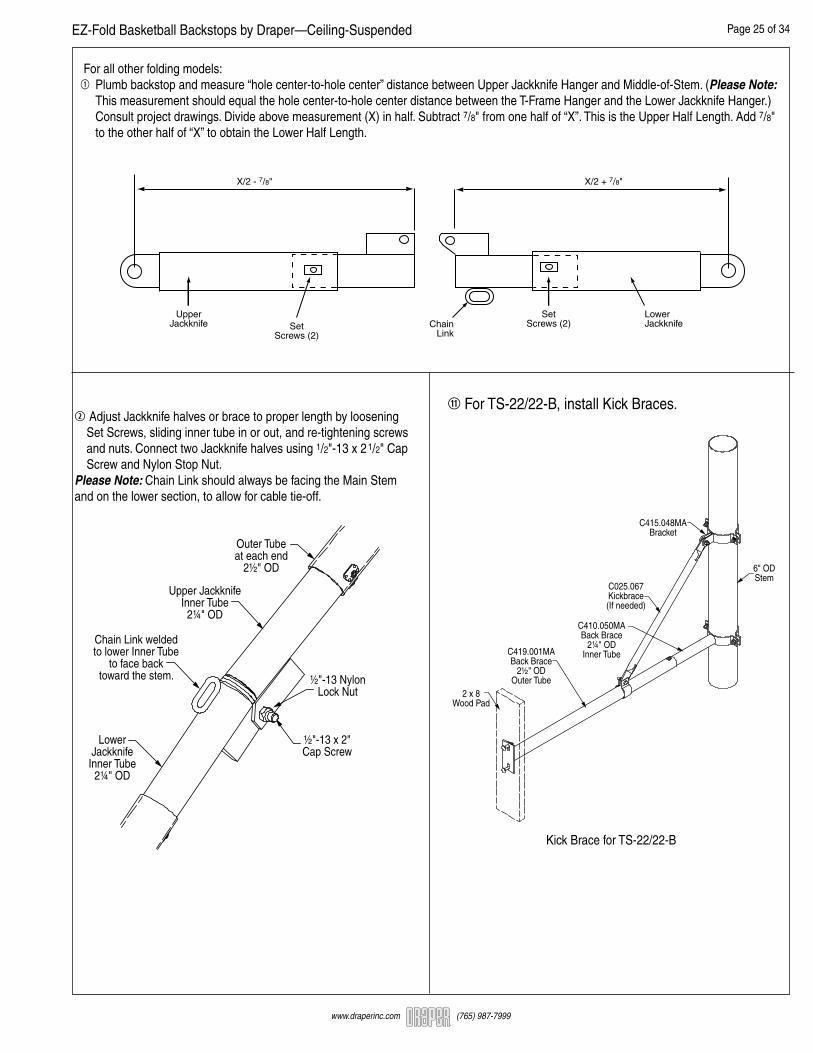
2 Adjust Jackknife halves or brace to proper length by loosening Set Screws, sliding inner tube in or out, and re-tightening screws and nuts. Connect two Jackknife halves using 1/2"-13 x 2 1/2" Cap Screw and Nylon Stop Nut.Please Note: Chain Link should always be facing the Main Stem and on the lower section, to allow for cable tie-off.
11 For TS-22/22-B, install Kick Braces.
C415.048MABracket
C410.050MABack Brace
2¼" ODInner Tube
C025.067Kickbrace(If needed)
C419.001MABack Brace
2½" ODOuter Tube
2 x 8Wood Pad
6" ODStem
Outer Tubeat each end
2½" OD
½"-13 NylonLock Nut
½"-13 x 2"Cap Screw
LowerJackknife
Inner Tube2¼" OD
Chain Link weldedto lower Inner Tube
to face backtoward the stem.
Upper JackknifeInner Tube
2¼" OD
For all other folding models:1 Plumb backstop and measure “hole center-to-hole center” distance between Upper Jackknife Hanger and Middle-of-Stem. (Please Note: This measurement should equal the hole center-to-hole center distance between the T-Frame Hanger and the Lower Jackknife Hanger.) Consult project drawings. Divide above measurement (X) in half. Subtract 7/8" from one half of “X”. This is the Upper Half Length. Add 7/8" to the other half of “X” to obtain the Lower Half Length.
X/2 - 7/8" X/2 + 7/8"
UpperJackknife
LowerJackknife
SetScrews (2)Set
Screws (2)Chain
Link
EZ-Fold Basketball Backstops by Draper—Ceiling-Suspended Page 26 of 34
www.draperinc.com (765) 987-7999
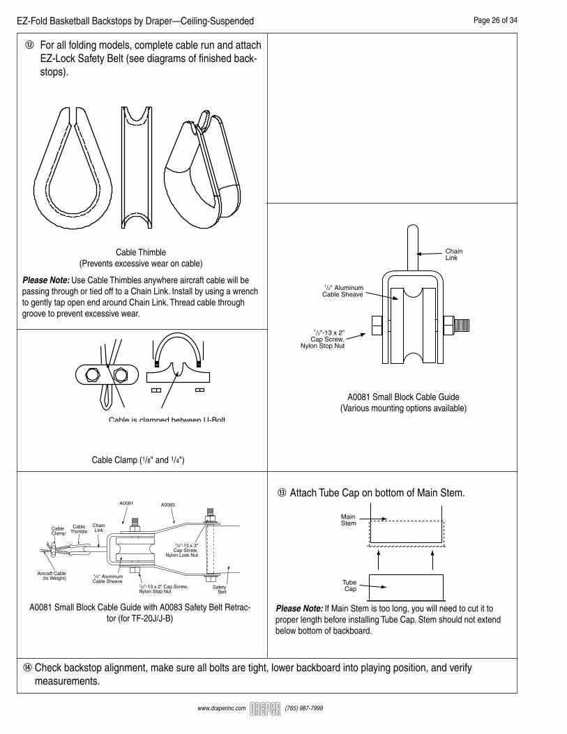
Cable is clamped between U-Boltand inverted "U" opening.
Cable Clamp (1/8" and 1/4")
Cable Thimble(Prevents excessive wear on cable)
A0081 Small Block Cable Guide(Various mounting options available)
1/2" AluminumCable Sheave
ChainLink
1/2"-13 x 2"Cap Screw,
Nylon Stop Nut
Please Note: Use Cable Thimbles anywhere aircraft cable will be passing through or tied off to a Chain Link. Install by using a wrench to gently tap open end around Chain Link. Thread cable through groove to prevent excessive wear.
12 For all folding models, complete cable run and attach EZ-Lock Safety Belt (see diagrams of finished back- stops).
A0081 Small Block Cable Guide with A0083 Safety Belt Retrac-tor (for TF-20J/J-B)
1/2"-13 x 2" Cap Screw,Nylon Stop Nut
1/2" AluminumCable Sheave
ChainLink
SafetyBelt
1/2"-13 x 3"Cap Screw,
Nylon Lock Nut
A0081 A0083
Aircraft Cable(to Weight)
CableClamp
CableThimble
14 Check backstop alignment, make sure all bolts are tight, lower backboard into playing position, and verify measurements.
Please Note: If Main Stem is too long, you will need to cut it to proper length before installing Tube Cap. Stem should not extend below bottom of backboard.
MainStem
TubeCap
13 Attach Tube Cap on bottom of Main Stem.
EZ-Fold Basketball Backstops by Draper—Ceiling-Suspended Page 27 of 34
www.draperinc.com (765) 987-7999
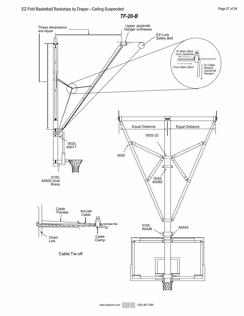
TF-20-B
Equal Distance Equal Distance
0033,A0082
0033 (2)
0035
0105,A0448 A0554
0033,A0017
0105,A0505 Goal
Brace
To Main Stemfrom Jackknife
From Main StemTo CableSheave(JackknifeHanger)
EZ-LockSafety Belt
These dimensionsare equal
Upper JackknifeHanger w/Sheave
CableThimble
ChainLink
CableClamp
AircraftCable
Cable Tie-off

EZ-Fold Basketball Backstops by Draper—Ceiling-Suspended Page 28 of 34
www.draperinc.com (765) 987-7999
TF-20S-B
INSTALLATION NOTE: Do not forget to account for the Main Stem angle when laying out and placing clamps for attachment. A good way to do this is to hold up the lower end of the backstop (with Top-of-T resting on floor) until lower portion of Main Stem is level (use carpenter’s level to check). Then, mea-sure the distance to the floor. The Main Stem angle is 22 degrees.
These distancesshould be the same.
A0510 Kick Brace Hanger,0033 6" x 2" Half Clamp
A0448 Jackknife Hanger,6" x 4" Half Clamp
A0510 and Half Clamp (2)
SafetyBelt
AircraftCable
Goal Brace,6" x 4" Half Clamp
To Main Stemfrom Jackknife
From Main Stem To CableSheave(JackknifeHanger)
Cable RunDetail
CableThimble
ChainLink
CableClamp
AircraftCable
Cable Tie-off

EZ-Fold Basketball Backstops by Draper—Ceiling-Suspended Page 29 of 34
www.draperinc.com (765) 987-7999
TF-20J-B
A0082
A0349
A0348
A0085
A0554
AircraftCable
SafetyBelt
A0081 A0083
CableThimble Aircraft
Cable SafetyBelt
Equal Distance Equal Distance
A0082
0033 (2)
0035
A0554
Goal BraceLatchAssembly
A0349
Cable Tie Offfor A0085
1/8" Cable

EZ-Fold Basketball Backstops by Draper—Ceiling-Suspended Page 30 of 34
www.draperinc.com (765) 987-7999
TB-25-B
Equal Distance Equal Distance
0033,A0082
0033 (2)
0035
0105,A0448 A0554
0033,A0017
0105,A0505 Goal
Brace
EZ-LockSafety Belt
These dimensionswill be the same
To Main Stemfrom Jackknife
From Main Stem To CableSheave(JackknifeHanger)
Upper JackknifeHanger w/Sheave
CableThimble
ChainLink
CableClamp
AircraftCable
Cable Tie-off
EZ-Fold Basketball Backstops by Draper—Ceiling-Suspended Page 31 of 34
www.draperinc.com (765) 987-7999
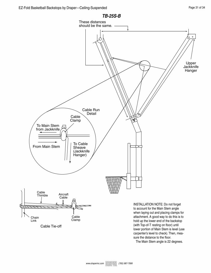
TB-25S-B
INSTALLATION NOTE: Do not forget to account for the Main Stem angle when laying out and placing clamps for attachment. A good way to do this is to hold up the lower end of the backstop (with Top-of-T resting on floor) until lower portion of Main Stem is level (use carpenter’s level to check). Then, mea-sure the distance to the floor. The Main Stem angle is 22 degrees.
These distancesshould be the same.
UpperJackknifeHanger
To Main Stemfrom Jackknife
From Main StemTo CableSheave(JackknifeHanger)
Cable Run Detail
CableClamp
CableThimble
ChainLink
CableClamp
AircraftCable
Cable Tie-off

EZ-Fold Basketball Backstops by Draper—Ceiling-Suspended Page 32 of 34
www.draperinc.com (765) 987-7999
TBS-26-B
Installation Note: Assemble on floor, as with other models, but attach bank sideways and a couple of inches above playing level. After backstop attachment, rotate and lower bank into playing position.
As indicated on Shop Drawings
0036
0038,A0453
02990033
A0449 or A0450,0105
0105,A0505
Goal Brace
To Main Stemfrom Jackknife
From Main Stem
To Cable Sheave(Jackknife Hanger)
CableClamp
These dimensionsare equal.
EZ-LockSafety Belt 1/4" Aircraft
Cable
A0554
CableThimble
ChainLink
CableClamp
AircraftCable
Cable Tie-off

EZ-Fold Basketball Backstops by Draper—Ceiling-Suspended Page 33 of 34
www.draperinc.com (765) 987-7999
TS-21-B
Upper BackBrace Hanger
BankHanger
Goal Brace
CircleClamp
6" x 2" HalfClamp (2)
Equal Distance Equal Distance
BackBrace
6" x 2" HalfClamp (2)

EZ-Fold Basketball Backstops by Draper—Ceiling-Suspended Page 34 of 34
www.draperinc.com (765) 987-7999
TS-22-B
BankHanger
A0510 KickBrace Hanger
CircleClamp
WoodWall Pad
Superstructure