installation instructions dd-40ntv-o, dd-40ntv...
TRANSCRIPT
INSTALLATION INSTRUCTIONS DIGITAL ANNUNCIATORDD-40NTV-O, DD-40NTV-U
DEVIATION FROM THESE INSTRUCTIONS MAY LEAD TO IMPROPER OP-ERATION OF THE MACHINE WHICH COULD CAUSE PERSONAL INJURY TO OPERATORS OR OTHER NEARBY PERSONNEL.
WARNING:
www.altronicinc.com
FORM DD-40NTV II 12-09
www.altronicinc.com 1
1.0 OVERVIEW
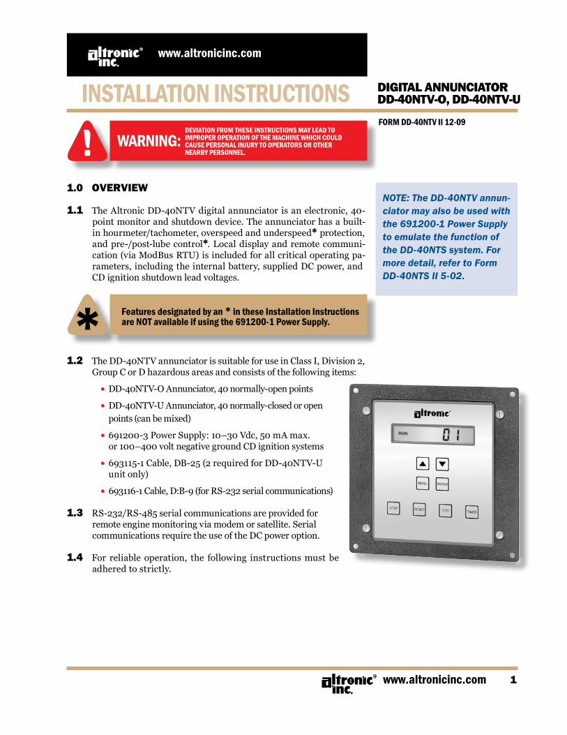
1.1 The Altronic DD-40NTV digital annunciator is an electronic, 40-point monitor and shutdown device. The annunciator has a built-in hourmeter/tachometer, overspeed and underspeed* protection, and pre-/post-lube control*. Local display and remote communi-cation (via ModBus RTU) is included for all critical operating pa-rameters, including the internal battery, supplied DC power, and CD ignition shutdown lead voltages.
1.2 The DD-40NTV annunciator is suitable for use in Class I, Division 2, Group C or D hazardous areas and consists of the following items:
• DD-40NTV-O Annunciator, 40 normally-open points
• DD-40NTV-U Annunciator, 40 normally-closed or open points (can be mixed)
• 691200-3 Power Supply: 10–30 Vdc, 50 mA max. or 100–400 volt negative ground CD ignition systems
• 693115-1 Cable, DB-25 (2 required for DD-40NTV-U unit only)
• 693116-1 Cable, D:B-9 (for RS-232 serial communications)
1.3 RS-232/RS-485 serial communications are provided for remote engine monitoring via modem or satellite. Serial communications require the use of the DC power option.
1.4 For reliable operation, the following instructions must be adhered to strictly.
DEVIATION FROM THESE INSTRUCTIONS MAY LEAD TOIMPROPER OPERATION OF THE MACHINE WHICH COULDCAUSE PERSONAL INJURY TO OPERATORS OR OTHERNEARBY PERSONNEL.
WARNING:
NOTE: The DD-40NTV annun-ciator may also be used with the 691200-1 Power Supply to emulate the function of the DD-40NTS system. For more detail, refer to Form DD-40NTS II 5-02.
Features designated by an * in these Installation Instructions are NOT available if using the 691200-1 Power Supply.

FORM DD-40NTV II 12-092
DD-40NTV DIGITAL ANNUNCIATOR
NOTE: If possible, keep the original shipping container. If future transportation or storage of the annunciator is necessary, this container will provide the optimum protection.
2.0 MOUNTING
2.1 ANNUNCIATOR UNIT: Using four #10 screws, mount the Annunciator Unit inside a control
panel or to a suitable flat surface so that the display is at a conve-nient viewing height. A drilling template is provided. The annun-ciator unit box must be grounded.
2.2 691200-3 POWER SUPPLY: The Power Supply mounts directly to the back of the Annunciator
Unit using two 8-32 x 5/16" length screws provided.
3.0 WIRING (FIGS. 7 – 20)
3.1 The annunciator unit plugs into the power supply through a DB-9 connector.
3.2 The sensor leads connect to the removable terminal strips on the back of the annunciator. These terminal strips match those used with the earlier DD-40NT/DD-20NT systems.
3.3 At the terminal strip of the Annunciator unit, strip the insulation back 3/8"; twist the exposed wires tightly together. Insert the ex-posed wire end completely into the terminal strip and securely tighten the clamping screw. It is suggested that wire 18 AWG (max.) to 24 AWG (min.) be used for the connections directly to the an-nunciator terminal strip connector.
3.4 Wires running to the various sensors should be in good condition or replaced with new wiring. Terminations to the main panel ter-minal strip (if used) should be made with a suitable terminal and crimping tool or by soldering. There is no requirement for explo-sion-proof conduit or Class I enclosures; however, suitable physical protection should be provided.
NOTE: Avoid mounting with the LCD display facing direct sunlight.
The display temperature range is -40°F. to +175°F.
WARNING: REGARDING OLDER ALTRONIC OVERSPEED DEVICESIF RETROFITTING INTO AN OLDER PANEL, THE DD-40NTV ANNUNCIATOR WILL NOT RECOGNIZE THE OUTPUT SIGNAL FROM OLDER ALTRONIC OVERSPEED DEVICES: DTO-1000, DTO-1010, DTO-2200, DTO-3200 DTHO-2100, DO-3300, PTO-2100, PTHO-2100
THESE DEVICES WILL NOT WORK FOR OVERSPEED PROTECTION IN CONJUNCTION WITH A DD-40NTV ANNUNCIATOR. FOR SUCH PROTECTION, USE THE OVERSPEED FEATURE BUILT INTO THE DD-40NTV ANNUNCIATOR (REFER TO SECTION 6.3).

www.altronicinc.com 3
DD-40NTV DIGITAL ANNUNCIATOR
4.0 ANNUNCIATOR CONFIGURATION
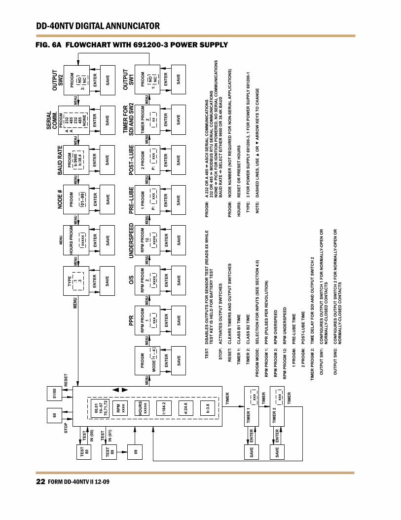
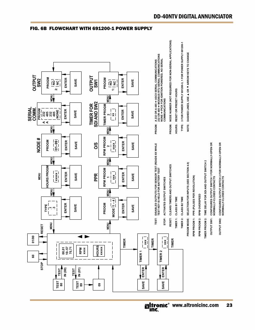
4.1 The DD-40NTV series unit MUST be configured prior to use. If re-placing an older series DD series annunciator, modes 1 and 4 can be used to directly emulate the older system’s performance. Mode 1 duplicates the operation of the DD-40 series and mode 4 dupli-cates the DD-20 series units. To configure the unit, press the MENU key to reach the configuration headings from the normal display mode. After a selection has been made, press the ENTER key to save the selection. Press MENU to move to the next step. A f lowchart (REFER TO FIG. 6A or 6B) is provided that shows step-by-step pro-gression through the annunciator configuration procedure.
CAUTION:A. SENSOR WIRING: SENSOR WIRES WITHIN THE PANEL ENCLOSURE
MUST BE KEPT AT LEAST TWO (2) INCHES FROM OTHER WIRING. USE A SEPARATE JUNCTION BOX FOR IGNITION AND FUEL VALVE WIRES. RUN SENSOR LEADS LEAVING THE PANEL IN A CONDUIT SEPARATE FROM ALL OTHER WIRING AND KEEP SEPARATE THROUGHOUT THE INSTALLATION. WIRING TO THE SENSORS MUST HAVE A GRADE OF INSULATION CAPABLE OF WITHSTANDING AN AC VOLTAGE OF 500 V. RMS. SENSOR LEADS MAY BE CONNECTED TO ANY PASSIVE DEVICE USING CONTACTS SUCH AS STANDARD SWITCH GAUGES OR LEVEL SWITCHES. DO NOT CONNECT SENSOR LEADS TO RELAY CONTACTS OR TO ANY VOLTAGE PRODUCING ELEMENT.
B. SENSORS WILL BE EXPOSED TO MUCH LOWER VOLTAGES AND CURRENT THAN WITH THE STANDARD MURPHY TATTLETALE OR SIMILAR TYPE SYSTEM. IN THE CASE OF A FIELD CONVERSION WHERE SENSORS HAVE PREVIOUSLY BEEN USED WITH MURPHY TATTLETALES, IT IS RECOM-MENDED THAT THE SENSORS BE CHECKED FREQUENTLY WHEN THE DD SYSTEM IS FIRST PUT INTO USE. SENSOR CONTACTS MAY BE BURNED OR PITTED FROM PAST EXPOSURE TO IGNITION SYSTEM PRIMARY VOLT-AGE. IT IS ADVISABLE TO REPLACE SUCH SENSORS.
C. IF IT BECOMES NECESSARY TO CHECK SENSOR TO PANEL WIRING WITH
AN OHMMETER OR OTHER CHECKER, FIRST DISCONNECT THE PLUG-IN TERMINAL STRIPS FROM THE BACK OF THE ANNUNCIATOR UNIT. APPLY-ING VOLTAGE TO THE ANNUNCIATOR THROUGH THE SENSOR LEADS MAY DAMAGE THE DEVICE. IN ADDITION, THE AREA SHOULD BE TESTED AS NON-HAZARDOUS BEFORE SUCH TESTING COMMENCES.
FORM DD-40NTV II 12-094
DD-40NTV DIGITAL ANNUNCIATOR
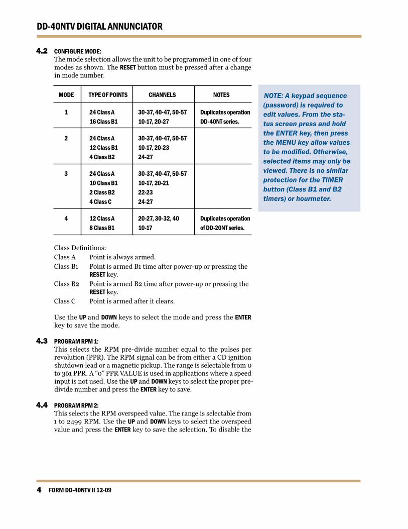
4.2 CONFIGURE MODE: The mode selection allows the unit to be programmed in one of four
modes as shown. The RESET button must be pressed after a change in mode number.
MODE TYPE OF POINTS CHANNELS NOTES
1 24 Class A 30-37, 40-47, 50-57 Duplicates operation 16 Class B1 10-17, 20-27 DD-40NT series.
2 24 Class A 30-37, 40-47, 50-57 12 Class B1 10-17, 20-23 4 Class B2 24-27
3 24 Class A 30-37, 40-47, 50-57 10 Class B1 10-17, 20-21 2 Class B2 22-23 4 Class C 24-27
4 12 Class A 20-27, 30-32, 40 Duplicates operation 8 Class B1 10-17 of DD-20NT series.
Class Definitions: Class A Point is always armed. Class B1 Point is armed B1 time after power-up or pressing the RESET key. Class B2 Point is armed B2 time after power-up or pressing the RESET key. Class C Point is armed after it clears.
Use the UP and DOWN keys to select the mode and press the ENTER key to save the mode.
4.3 PROGRAM RPM 1: This selects the RPM pre-divide number equal to the pulses per
revolution (PPR). The RPM signal can be from either a CD ignition shutdown lead or a magnetic pickup. The range is selectable from 0 to 361 PPR. A “0” PPR VALUE is used in applications where a speed input is not used. Use the UP and DOWN keys to select the proper pre-divide number and press the ENTER key to save.
4.4 PROGRAM RPM 2: This selects the RPM overspeed value. The range is selectable from
1 to 2499 RPM. Use the UP and DOWN keys to select the overspeed value and press the ENTER key to save the selection. To disable the
NOTE: A keypad sequence (password) is required to edit values. From the sta-tus screen press and hold the ENTER key, then press the MENU key allow values to be modified. Otherwise, selected items may only be viewed. There is no similar protection for the TIMER button (Class B1 and B2 timers) or hourmeter.

www.altronicinc.com 5
DD-40NTV DIGITAL ANNUNCIATORoverspeed function, enter 2500.
4.5 PROGRAM RPM 12*: This selects the RPM underspeed value. The range is selectable from
0 to 2500 RPM. Use the UP and DOWN keys to select the underspeed value and press the ENTER key to save the selection. To disable the underspeed function, enter 2500.
4.6 PROGRAM PRE-LUBE P1*: This selects the time delay in seconds for which the LUBE (LUB) out-
put is actuated on start-up. The range is from 1 to 999 seconds. Use the UP and DOWN keys to select the desired pre-lube time (in sec-onds) and press the ENTER key to save the selection. Entering a value of zero (0) as the setpoint disables the pre-lube function.
4.7 PROGRAM POST-LUBE P2*: This selects the time delay in seconds for which the LUBE (LUB)
output is actuated following a manual STOP or SHUTDOWN. The range is from 1 to 999 seconds. Use the UP and DOWN keys to select the desired post-lube time (in seconds) and press the ENTER key to save the selection. Entering a value of zero (0) as the setpoint dis-ables the post-lube function.
4.8 PROGRAM TIMER 2: This selects the time delay in seconds for tripping SDI and OUTPUT
2 after a fault occurs. The range of the delay is from 1 to 60 seconds. Use the UP and DOWN keys to select the time and press the ENTER key to save the selection. In typical applications, SW1 is used to turn off the fuel and either SDI or SW2 is used to turn off the ignition.
4.9 PROGRAM SW1: This selects the RUN state of output SW1, normally open (N.O.) or
normally closed (N.C.). Use the UP and DOWN keys to select the state and press ENTER to save.
4.10 PROGRAM SW2: This selects the RUN state of output SW2, normally open (N.O.) or
normally closed (N.C.). Use the UP and DOWN keys to select the state and press ENTER to save.
4.11 PROGRAM SERIAL MODE: This selects the type of communications used by the annunciator.
Selections are provided for NONE (must be used for ignition pow-ered applications), RS-232 ASCII (A 232), RS-232 Modbus RTU (232), RS-485 ASCII (A 485), or RS-485 Modbus RTU (485). Use the UP and DOWN keys to select the state and press ENTER to save.
4.12 PROGRAM BAUD RATE*: This selects the baud rate for communications. Select either 9600 or
38.4k baud. Use the UP and DOWN keys to select the baud rate and press the ENTER key to save the selection. This applies only for serial commu-nications and need not be programmed for non-serial applications.
FORM DD-40NTV II 12-096
DD-40NTV DIGITAL ANNUNCIATOR
4.13 PROGRAM NODE NUMBER: This selects the node number for the annunciator. The range of the
node number is from 01 to 99. Use the UP and DOWN keys to select the node number and press the ENTER key to save the selection. This ap-plies only for serial communications and need not be programmed for non-serial applications.
4.14 PROGRAM HOURS: This selects the pre-programmed number of hours. The range is
from 00000 to 99999 hours. Press the UP and DOWN arrow keys to modify the hours, then press the ENTER key to save.
4.15 PROGRAM TYPE: This selects the type of Power Supply being used with the system;
type.1 for 691200-1 (NTS mode) or type.3 for 691200-3 (NTV mode).
4.16 TIMER KEY: This selects the B1 and B2 timer delays. The range is from 1 to 999
seconds. Pressing the TIMER key once displays the B1 timer, and pressing the TIMER key again displays the B2 timer. Use the UP and DOWN keys to change the respective B timer and press the ENTER key to save the selection.
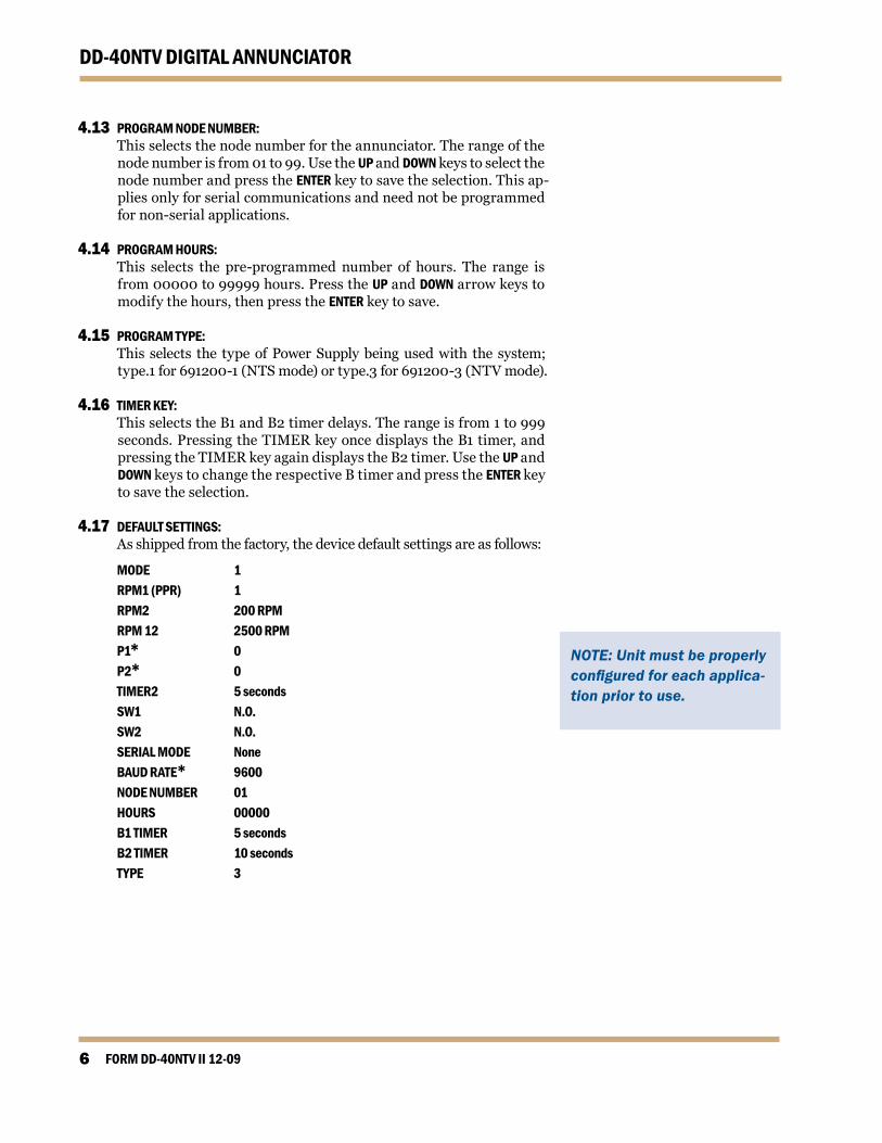
4.17 DEFAULT SETTINGS: As shipped from the factory, the device default settings are as follows:
MODE 1 RPM1 (PPR) 1 RPM2 200 RPM RPM 12 2500 RPM P1* 0 P2* 0 TIMER2 5 seconds SW1 N.O. SW2 N.O. SERIAL MODE None BAUD RATE* 9600 NODE NUMBER 01 HOURS 00000 B1 TIMER 5 seconds B2 TIMER 10 seconds TYPE 3
NOTE: Unit must be properly configured for each applica-tion prior to use.

www.altronicinc.com 7
DD-40NTV DIGITAL ANNUNCIATOR
5.0 KEYPAD DESCRIPTION/FUNCTION
5.1 MENU: This key allows the user to view/change the following:
• Mode selection • Pulses per revolution • Overspeed value • Underspeed value* • Pre-lube on-time* • Post-lube on-time* • Output switch 1 • Output switch 2 • Communications • Baud rate* • Output timer 2 • Node number • Programmed hours • Power Supply Type
5.2 UP ARROW: This key is used to increment/modify selections and allows the user to
view the current RPM, the hourmeter reading, annunciator status, and all of the monitored electrical voltages* (back-up battery, external DC power, and CD ignition power.
5.3 DOWN ARROW: This key is used to decrement/modify selections and allows the user to
view the current RPM, the hourmeter reading, annunciator status, and all of the monitored electrical voltages (back-up battery, external DC power, and CD ignition power.
5.4 ENTER: This key allows for selected items to be saved. When pre- or post-
lubing, pressing the ENTER key will also cancel lubrication.
5.5 STOP: This key initiates a shutdown condition and the unit will display a
status of [60]. This has precedence over all other functions.
5.6 RESET: This key clears any faults and resets the Class B1 and B2 timers. If
the pre-lube function is active, RESET also actuates the LUB output.* The annunciator displays [00] if one or more points is not armed. Once all the channels are armed, the display reads [01]. The annun-ciator will power up in the RESET mode. The unit will not reset the outputs if any of the Class A points are faulted.
LOOPS TO HOME SCREEN
FROM THE HOME SCREEN
BATTERY VOLTAGE*
EXTERNAL DC POWER VOLTAGE*
CD IGNITION SHUTDOWN LEAD VOLTAGE*
PRESS
I: 186.2
24.38:
3.66:
0 1PRESS
PRESS
PRESS
PRESS
0005 6
100 3PRESS
RPM
HOURS

FORM DD-40NTV II 12-098
DD-40NTV DIGITAL ANNUNCIATOR
5.7 TEST: This key provides for battery and operating voltage tests and also
allows inputs to be tested (faulted) without causing a shutdown. The battery in the Power Supply may be checked when the machine is down and the display reads [00]; push and hold the TEST key – a read-ing of [80] indicates satisfactory battery voltage. The operating volt-age may be checked when the machine is operating and the display reads [01]; push and hold the TEST key – a reading of [89] indicates the operating voltage is acceptable. To test the sensor input points, the annunciator must first be displaying [01] meaning all points are armed. Push and release the TEST key, and the display will read [09] indicating the Test Mode. Faulted points will be displayed but will not cause the outputs to trip. Testing an additional point requires the TEST key to be pressed again. The annunciator will remain in test mode for two minutes before reverting back to the running mode [01]. Any point not cleared in two minutes (either by pressing the TEST or RESET key) will cause the outputs to trip.
5.8 TIMER: This key allows the B1 and B2 delay timers to be viewed or modified.
5.9 KEYPAD SEQUENCE (PASSWORD) PROTECTION: From the status screen, press and hold the ENTER key, then press the
MENU key to allow values to be modified. Otherwise, the selected items may only be viewed. There is no keypad sequence protection for the TIMER key (Class B1 and B2 timers).
5.10 CANCEL TIMERS: From the status screen, depress the ENTER key. While holding the ENTER
key, also press the DOWN ARROW key.
6.0 OPERATION See chart on next page.
NOTE: Two fault occurrences will override the TEST mode: manual STOP function [60] and OVERSPEED [70].

www.altronicinc.com 9
DD-40NTV DIGITAL ANNUNCIATOR
NOTE:
a.) TEST cannot be used until the start-up timer interval ends – [01] on the display.
b.) A display reading of [09] means the system output will not activate unless the STOP button is pushed.
c.) Do not leave a sensor number on the display after the last test; push the TEST button to get [09] on the display; then wait two minutes until [01] displays or select the CANCEL TIMERS feature.
d.) For a complete system test, allow the test timer interval to expire – display changes from [09] to [01] – then cause one sensor to fault and allow the sys-tem output to activate. This will test the entire sys-tem for correct operation upon a fault with minimal downtime.
6.1 OPERATING SEQUENCE MACHINE DISPLAY FUNCTION DESCRIPTION Down [10-57] Shutdown Shutdown caused by the fault number
indicated. Number will remain until fault is corrected and RESET button depressed.
[60] Shutdown Shutdown caused by depressing STOP button.
[70] Shutdown Shutdown caused by overspeed.
[71] Shutdown Shutdown caused by loss of RPM signal.
[72]* Shutdown Shutdown caused by underspeed. This is a Class C function which is armed when the setpoint is exceeded by 100 RPM.
[80] Shutdown Push TEST button when down, indicates battery is OK.
[00] Reset Before starting machine, momentarily push the RESET button. A display of [00] indicates all Class A sensors are ready for start-up. Any number 10-57 indcates a faulted sensor that must be cleared before start-up.
[60] Engine Purge To purge engine prior to start, depress the STOP button, roll the engine to purge, then push the RESET button. Engine can then be started provided display reads [00].
[61] Shutdown Shutdown caused by DE, a serial stop command.
Running [00] Start-up Start-up timers have Class B1 and B2 points disarmed. All Class A points are being monitored. Pushing the RESET button re-cycles the start-up timers. To cancel the start-up timers, press the ENTER key, followed by the DOWN key while still depressing the ENTER key.
[01] Normal All points are being monitored. The transi- tion from [00] to [01] indicates the end of
the last start-up timer interval.
[89] Test From [01] display, press and hold TEST button; indicates adequate operating voltage.
[09] Test Press and release TEST button – a timed test period is initiated for approximately two
minutes. As a sensor is faulted, its number is latched on the display (but the output is not activated). To move to the next point, firstclearthesensor,thenpushtheTEST button again. The display reverts to [09] until the next sensor is faulted. After the last test, push the TEST button to get [09] on the display; wait two minutes until [01] displays.
[01] Normal Test period has ended; all points are being monitored. DO NOT LEAVE MACHINE UN- LESS DISPLAY READS [01].
FORM DD-40NTV II 12-0910
DD-40NTV DIGITAL ANNUNCIATOR
6.2 RPM/HOURMETER: Press the UP and DOWN keys to view the RPM, hourmeter and volt-
ages*. The RPM screen remains until the operator chooses another option. The HOURS display will revert to the status screen after two minutes. In either case, the annunciator will display the fault num-ber when a shutdown occurs.
6.3 RPM OVERSPEED PROTECTION: The DD-40NTV annunciator has a built in tachometer to monitor
engine overspeed. When the detected RPM is greater than the RPM overspeed setpoint, the annunciator will trip the fuel and ignition outputs. When this occurs, the unit will display [70] and activate the FAULT indicator. REFER TO FIGS. 7 — 20 for the further details.
6.4 RPM UNDERSPEED PROTECTION*: The DD-40NTV annunciator has a built in tachometer to monitor
engine underspeed. This point is armed when the underspeed set-point is exceeded by 100 RPM. Once armed, should the monitored RPM fall below the setpoint, the annunciator will trip the fuel and ignition outputs. When this occurs, the unit will display [72] and activate the FAULT indicator. REFER TO FIGS. 7 — 20 for further details.
6.5 BATTERY: The Power Supply contains a special long-life lithium battery. When
the monitored equipment is not operating, current draw from the battery is only microamps (millionths of amps). When the annun-ciator is powered, there is no drain from the battery. This allows for a battery life of up to 5 years in normal operation. The battery in the power supply is replaceable; use ONLY Altronic part no. 601952. Be sure to observe the proper polarity as marked in the Power Sup-ply when replacing the battery.
THE DD-40NTV ANNUNCIATOR WILL NOT RECOGNIZE THE OUTPUT SIGNAL FROM AN ALTRONIC DTO-3200 OR OTHER OLDER OVERSPEED DEVICES (SEE LISTING ON PAGE 2). THESE DEVICES WILL NOT WORK FOR OVERSPEED PROTEC-TION IN CONJUNCTION WITH A DD-40NTV ANNUNCIATOR.FOR SUCH PROTECTION, USE THE OVERSPEED FEATURE BUILT INTO THE DD-40NTV ANNUNCIATOR.
WARNING:
www.altronicinc.com 11
DD-40NTV DIGITAL ANNUNCIATOR
7.0 FAULT OUTPUTS
7.1 Two digital outputs, SW1 and SW2 are in the Power Supply. These are rated 400 volts DC, 0.5 amp maximum.
7.2 Output SW1 will trip immediately upon a fault condition or if the
STOP key is depressed. 7.3 Outputs SDI and SW2 will trip after a pre-programmed time delay
(TIMER PROGM2) from either a fault condition or if the STOP key is depressed.
7.4 For Power Supplies 691200-1 and 691200-3, the maximum voltage
is 400 volts from a negative ground C.D. ignition with a current drain of microamps. The maximum current rating is 50 mA when powered from a DC voltage source of 10 to 30 volts.

FORM DD-40NTV II 12-0912
DD-40NTV DIGITAL ANNUNCIATOR
8.0 PRE-LUBE/POST-LUBE OUTPUT*8.1 One (1) digital output LUB is located in the power supply 691200-3*.
It is rated 400 volts DC, 0.5 amp maximum.
8.2 Output LUB will be actuated under two operating conditions:
• Following a RESET (remote or manual), the LUB output will remain actuated until the pre-lube timer (P1) expires. • Following a manual STOP or FAULT, the LUB output will remain actuated until the post-lube timer (P2) expires.
9.0 SERIAL COMMUNICATIONS
9.1 Serial communications may be selected as RS-232 or RS-485 using ASCII or Modbus RTU protocol.
9.2 MASTER/SLAVE OPERATION: The RS-485 communication system in the annunciator is designed
as a master/slave system; that is, each unit responds to its own unique address (node number) only after it is interrogated by the master (computer). A simple command/response protocol must be strictly observed.
9.3 NODE NUMBER: The node number is used in the system to identify the desired slave
unit being polled. The node number can be any numeric value from 1 to 99.
9.4 ASCII COMMUNICATION: All communication to and from the annunciator is performed using
ASCII characters. This allows the information to be processed with the “string” functions common to high level computer languages such as BASIC and C. For computers that support standard serial port interfaces, no special machine language software drivers are required. The use of the ASCII format also allows for the connec-tion of these devices to an auto answer modem for long distance operation without the need for a local supervisory computer. The ASCII characters also make system debugging easy using standard terminal emulation software.
9.5 COMMUNICATIONS PARAMETERS:
• Baud Rate: 9600 or 38.4k* • Data Bits: 8 • Stop Bits: 1 • Parity: None
NOTE: The letter “L” will ap-pear in the display when the LUB output has been actu-ated. To cancel the pre-lube or post-lube countdown tim-ers, press the ENTER key. If pre-lubing, the annunciator will immediately initiate the Class B timer(s).

www.altronicinc.com 13
DD-40NTV DIGITAL ANNUNCIATOR
9.6 COMMAND STRUCTURE: The annunciator operates with a simple command/response protocol
to monitor all functions. A command must be transmitted to the unit by the master (computer or PLC) before the slave can respond with use-ful data. A slave unit can never initiate a communications sequence.
Communication to the annunciator is performed with two character ASCII command codes. The general format used for the commands is illustrated below using the READ DATA command as an example. The hexadecimal values for the characters are shown only as a reference for those using low level (assembly language) decoding and will not appear on the communications terminal screen. All of the characters used in the communications protocol are standard ASCII characters and ap-pear on the computer keyboard as shown with the exception of the “not acknowledge” (NAK) which is the industry standard “control U”.
header start node space command end ASCII > ( 01 R D ) HEX 3Eh 28h 30h 31h 20h 52h 44h 29h
Command Header “>” (3Eh): Each command must begin with the command header sometimes
referred to as a prompt character. The ASCII character used is the “>” which means that a command message will be sent from the master to the slave.
Start of Text “(” (28h): The command header must be followed by the start of text indicator. Node Number “01 -99” (30h 31h): The node number or address of the device being contacted.
Space (20h): Following the node number is an ASCII space character (not print-
able, value 20h) to act as a delimiter between the node number and the two character command word.
Command Word “RD” (52h, 44h): The command words are standard two letter (upper case) com-
mands sent by the master for gathering specific information about the status of a slave. The commands are listed under STANDARD COMMANDS below.
End of Text “)” (29h): The end of text indicator says this is the end of the command.

FORM DD-40NTV II 12-0914
DD-40NTV DIGITAL ANNUNCIATOR
STANDARD COMMANDS Information coming from serial command(s) Command Response Notes
Annunciator status >(01 RD) <(01 XX) (XX - Refer to section 6.0) Read hourmeter >(01 RH) <(01 XXXXX) (XXXXX = Hours) Read current RPM >(01 RP) <(01 XXXX) (XXXX = RPM) Reset the annunciator >(01 RR) <(01 RR) Stop the annunciator >(01 RS) <(01 RS)
Valid Response: A command/response sequence is not complete until a valid re-
sponse is received. When a slave unit receives a valid command, it interprets the command, performs the desired function and then communicates the response to the master within 20mS. The master may not initiate a new command until the response from a previous command is completed.
A valid response can occur in three ways: • A normal response indicated by a “<” header and “( )” beginning
and end of text. • An error response indicated by a “§” NAK (not acknowledged). • A communications time-out error.
An NAK error response will be sent by the annunciator when it has received a command with an error in the message. All commands must be of the format above. The header, start-and-end of text char-acters, a valid node number and spaces must be sent and correct to receive an NAK; if not, no response will be sent.
9.7 RS-485 COMMUNICATIONS:
• HALF DUPLEX OPERATION: The RS-485 system employed uses two wires for communica-
tion and cannot send and receive data at the same time over the same two wires making it a half duplex system. When the master is in the transmit mode, the slave is in the receive mode and visa-versa.
• ELECTRICAL OPERATING RANGE: RS-485 is a communications standard to satisfy the need for
multi-dropped systems that can operate at high speeds over long distances. RS-485 uses a balanced differential pair of wires switching from 0 to 5 volts to communicate data. RS-485 drivers can handle common mode voltages from −7 to +12 volts without loss of data, making them an excellent choice for indus-trial environments.

www.altronicinc.com 15
DD-40NTV DIGITAL ANNUNCIATOR
• COMMUNICATIONS WIRING: The RS-485 wiring diagram illustrates the wiring required for
multiple slave unit hookup. Note that every slave unit has a di-rect connection to the master. This allows any one slave unit to be removed from service without affecting the operation of the other units. Every unit must be programmed with a unique address or node number, but the addition of new units or nodes can be in any order. To minimize unwanted reflections on the transmission line, the bus should be arranged as a trunk line going from one module to the next. Random structures of the transmission line should be avoided. Special care must be taken with long busses (500 feet or more) to ensure error free opera-tion. Long busses must be terminated with a 120 ohm resistor between the terminals marked RS-485 “A” and RS-485 “B” at the master only. The use of twisted pair shielded cable will en-hance signal fidelity and is recommended. To prevent ground loops the shield should be connected to the shield terminal at the master only.
• LOADING: RS-485 uses a balanced differential pair of wires switching
from 0 to 5 volts to communicate data. In situations where many units (99 max.) are connected together on a long run, voltage drop on the communications leads becomes a major problem. Voltage drops on the RS-485 minus lead appear as a common mode voltage to the receivers. While the receivers are rated to a maximum voltage difference of ±7 volts, −7V to +12V, a practical system should not have a voltage difference exceeding ±3 volts under normal conditions. The wire gauge used for the connections limits the maximum number of units or the maximum length of wire between units in each applica-tion. The following formula can be used as a guideline to select the appropriate wire gauge.
For 18 AWG wire No. of annunciator units = (4000)/(ft of wire used) For 20 AWG wire No. of annunciator units = (3600)/(ft of wire used) For 22 AWG wire No. of annunciator units = (2400)/(ft of wire used)
NOTE: The maximum number of units that can be connect-ed in a system is 99.
FORM DD-40NTV II 12-0916
DD-40NTV DIGITAL ANNUNCIATOR
9.8 RS-232 COMMUNICATIONS: • For proper operation, the wire length should not exceed 50 feet.
• Use standard DB-9 connector and computer cable Altronic 693 116-x or equivalent.
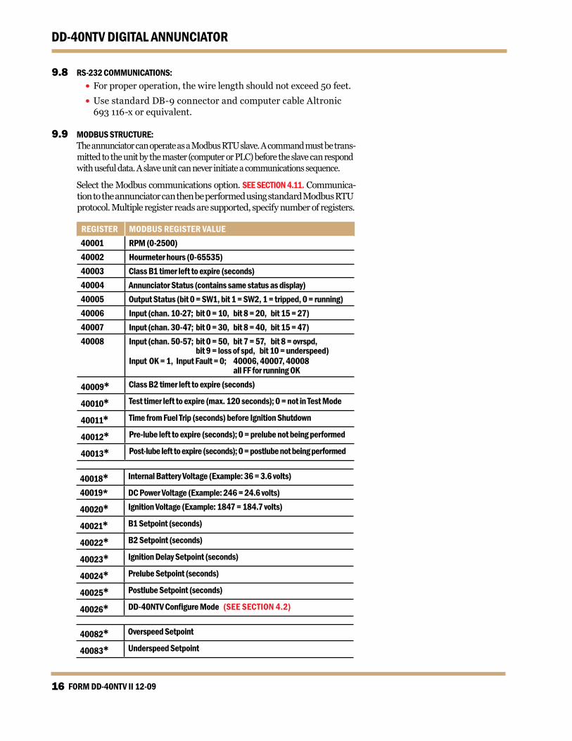
9.9 MODBUS STRUCTURE: The annunciator can operate as a Modbus RTU slave. A command must be trans-
mitted to the unit by the master (computer or PLC) before the slave can respond with useful data. A slave unit can never initiate a communications sequence.
Select the Modbus communications option. SEE SECTION 4.11. Communica-tion to the annunciator can then be performed using standard Modbus RTU protocol. Multiple register reads are supported, specify number of registers.
REGISTER MODBUS REGISTER VALUE40001 RPM (0-2500)40002 Hourmeter hours (0-65535)40003 Class B1 timer left to expire (seconds)40004 Annunciator Status (contains same status as display)40005 Output Status (bit 0 = SW1, bit 1 = SW2, 1 = tripped, 0 = running)40006 Input (chan. 10-27; bit 0 = 10, bit 8 = 20, bit 15 = 27)40007 Input (chan. 30-47; bit 0 = 30, bit 8 = 40, bit 15 = 47)40008 Input (chan. 50-57; bit 0 = 50, bit 7 = 57, bit 8 = ovrspd,
bit 9 = loss of spd, bit 10 = underspeed)Input OK = 1, Input Fault = 0; 40006, 40007, 40008 all FF for running OK
40009* Class B2 timer left to expire (seconds)
40010* Test timer left to expire (max. 120 seconds); 0 = not in Test Mode
40011* Time from Fuel Trip (seconds) before Ignition Shutdown
40012* Pre-lube left to expire (seconds); 0 = prelube not being performed
40013* Post-lube left to expire (seconds); 0 = postlube not being performed
40018* Internal Battery Voltage (Example: 36 = 3.6 volts)
40019* DC Power Voltage (Example: 246 = 24.6 volts)
40020* Ignition Voltage (Example: 1847 = 184.7 volts)
40021* B1 Setpoint (seconds)
40022* B2 Setpoint (seconds)
40023* Ignition Delay Setpoint (seconds)
40024* Prelube Setpoint (seconds)
40025* Postlube Setpoint (seconds)
40026* DD-40NTVConfigureMode(SEE SECTION 4.2)
40082* Overspeed Setpoint
40083* Underspeed Setpoint

www.altronicinc.com 17
DD-40NTV DIGITAL ANNUNCIATOR
FIG. 1 SPECIFICATIONS AND DIMENSIONS, DD-40NTV-O
MENU
STOP TEST
ENTER
TIMERRESET
TESTTIMER 1 2RUNFAULT
MODERPMHOURSPROGM
6.50
3.50
2.38
.88
6.00
.203 DIA.(TYP 4)
6.00
6.50
SPECIFICATIONS:
POWER REQUIRED: DC POWERED 12–24 VDC, 5 WATTS TYPICAL OR CD IGNITION SYSTEM 100 VOLTS MINIMUM.
INPUTS: RPM SIGNAL FROM CD IGNITION OR PICKUP.40 DISCRETE SWITCH INPUTS NORMALLY OPEN.4 SELECTABLE OPERATING MODES FOR NUMBER OFCLASS A, B (TWO TIMERS B1, B2) AND C SENSORS.
MODE A B1 B2 C1 24 16 0 02 24 12 4 03 24 10 2 44 12 8 0 0
OUTPUTS: 3 DIGITAL OUTPUTS.AUXILIARY TERMINALS FOR CD IGNITION SHUTDOWN ANDFUEL VALVE TRIP, PROGRAMMABLE DELAY TIME ON OUTPUT SW2.
FEATURES: INTEGRATED UNDERSPEED, OVERSPEED TACHOMETER ANDRUNTIME HOURMETER, PRE-LUBE/POST-LUBE.
DISPLAY CUSTOM 5-DIGIT LCD DISPLAY.
SCAN RATE: SCANS ALL 40 DISCRETE SWITCHES 5 TIMES/SECOND.
OPERATING TEMPERATURE RANGE: – 40° C TO + 80° C (– 40° F TO 176° F)
COMMUNICATIONS: RS–232 OR RS–485, CONNECTION ON POWER SUPPLY (DC POWER REQUIRED)
HAZARDOUS AREA CLASSIFICATION: CLASS 1, DIV. 2, T4, GROUP C & D.
RS–232DO NOT CONNECTIF HAZARDOUSCONDITION EXISTS
IGN INPUT 100–400VDC INPUT 10–30VDC50 mA MAX.
DD–40NTV–OS/N
CERTIFIED FOR USE INCLASS I, DIV. 2, GROUPC & D AREASU.S. Patent 6,738,244
Tx Rx
P/N 691200–3 S/N
GIRARD, OHIO
GIRARD, OHIO
INSTALL PER FORM DD-40NTV IICERTIFIED CLASS I,DIV 2, GRP C & D
ANNUNCIATOR POWER SUPPLY24V
IGN
B A
RS485
PU
RR
LUB
SW1
FVA
SW2
SDI
+ IG SD S2 FV S1 LB RR PU B A
NOTE: REQUIRES SQUARE OPENING OF 5.60"

FORM DD-40NTV II 12-0918
DD-40NTV DIGITAL ANNUNCIATOR3.
50
2.38
.88
4.00
1.85
2.50
6.35
7.00
.50
.190
DIA
.(T
YP)
6.00
DB-2
5 CA
BLE
P/N
6931
15
N/O
SWIT
CHN/
CSW
ITCH
UNUS
EDO
UTPU
TN/
OSW
ITCH
N/C
SWIT
CHUN
USED
OUT
PUT
TERM
INAL
BO
ARDS
P/N
6721
69
NO
N-IN
CEN
DIV
EFI
ELD
WIR
ING
ON
LYN
ON
-INC
END
IVE
FIEL
D W
IRIN
G O
NLY
34 3
5 36
37
40 4
1 42
43
44 4
5 46
47
50 5
152
53
5455
56
57C
1011
12
13 1
415
1617
2021
2223
24
25 2
6 27
3031
3233
C
.203
DIA
.(T
YP 4)
6.00
RS–2
32DO
NOT
CON
NECT
IF H
AZAR
DOUS
COND
ITIO
N EX
ISTS
Tx R
x
P/N
69
1200
–3
S/N
GIR
AR
D, O
HIO
INST
ALL
PER
FO
RM
DD
-40N
TV II
CE
RTI
FIE
D C
LAS
S I,
DIV
2, G
RP
C &
D
AN
NU
NC
IATO
R P
OW
ER
SU
PP
LY24
VI G N
BA
RS48
5
P UR R
L U B
S W 1
F V A
S W 2
S D I
+
IG
SD S
2 F
V S
1 L
B R
R P
U B
A
DD–4
0NTV
–US/
NG
IRA
RD
, OH
IO
MENU
STOP
TEST
ENTE
R
TIMER
RESE
T
TEST
TIMER
1 2
RUN
FAUL
T
MODE
RPM
HOUR
SPR
OGM
6.50
6.50
SPEC
IFIC
ATIO
NS:
POW
ER R
EQU
IRED
: D
C P
OW
ERED
12–
24 V
DC
, 5 W
ATTS
TYP
ICA
L O
R
C
D IG
NIT
ION
SYS
TEM
100
VO
LTS
MIN
IMU
M.
INPU
TS:
RPM
SIG
NA
L FR
OM
CD
IGN
ITIO
N O
R P
ICK
UP.
40 D
ISC
RET
E SW
ITC
H IN
PUTS
NO
RM
ALL
Y O
PEN
.4
SELE
CTA
BLE
OPE
RAT
ING
MO
DES
FO
R N
UM
BER
OF
CLA
SSA
, B (T
WO
TIM
ERS
B1,
B2)
AN
D C
SEN
SOR
S.
MO
DE
A B
1B
2C
124
160
02
2412
40
324
102
44
128
00
OU
TPU
TS:
2 D
IGIT
AL
OU
TPU
TS, P
RO
GR
AM
MA
BLE
, N.O
. OR
N.C
.A
UXI
LIA
RY T
ERM
INA
LS F
OR
CD
IGN
ITIO
N S
HU
TDO
WN
AN
DFU
ELVA
LVE
TRIP
, PR
OG
RA
MM
AB
LE D
ELAY
TIM
E O
N O
UTP
UT
SW2.
FEAT
UR
ES:
INTE
GR
ATED
UN
DER
SPEE
D, O
VER
SPEE
D T
AC
HO
MET
ERA
ND
RU
NTI
ME
HO
UR
MET
ER, P
RE-
LUB
E/PO
S T-L
UB
E.
DIS
PLAY
C
UST
OM
5-D
IGIT
LC
D D
ISPL
AY.
SCA
N R
ATE:
SCA
NS
ALL
40
DIS
CR
ETE
SWIT
CH
ES 5
TIM
ES/S
ECO
ND
.
OPE
RAT
ING
TEM
PER
ATU
RE
RA
NG
E:
– 40
° C T
O +
80°
C (–
40°
F T
O 1
76° F
)
CO
MM
UN
ICAT
ION
S:R
S–23
2 O
R R
S–48
5, C
ON
NEC
TIO
N O
N P
OW
ER S
UPP
LY
(D
C P
OW
ER R
EQU
IRED
)
HA
ZAR
DO
US
AR
EA C
LASS
IFIC
ATIO
N:
CLA
SS 1
, DIV
. 2, T
4, G
RO
UP
C &
D.
U.S.
Pat
ent 6
,738
,
NOTE: REQUIRES SQUARE OPENING OF 5.60"
FIG. 2 SPECIFICATIONS AND DIMENSIONS, DD-40NTV-U
www.altronicinc.com 19
DD-40NTV DIGITAL ANNUNCIATOR
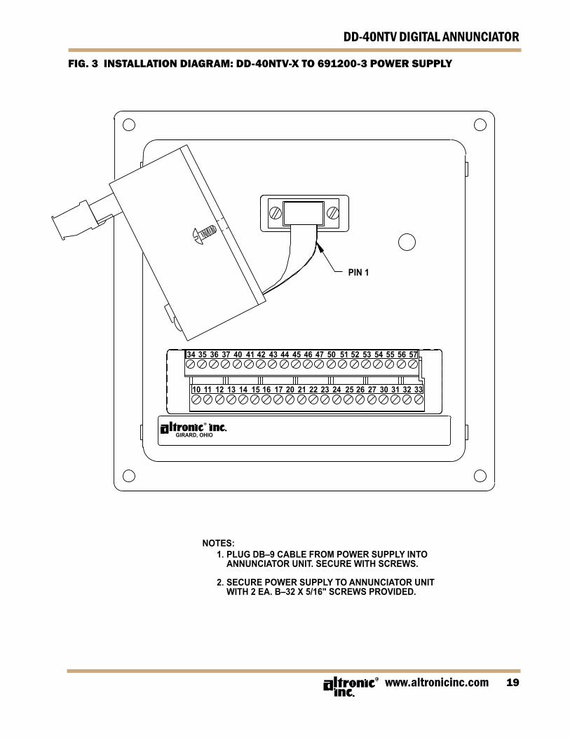
FIG. 3 INSTALLATION DIAGRAM: DD-40NTV-X TO 691200-3 POWER SUPPLY
PIN 1
GIRARD, OHIO
NOTES: 1. PLUG DB–9 CABLE FROM POWER SUPPLY INTO ANNUNCIATOR UNIT. SECURE WITH SCREWS.
2. SECURE POWER SUPPLY TO ANNUNCIATOR UNIT WITH 2 EA. B–32 X 5/16" SCREWS PROVIDED.
34 35 36 37 40 41 42 43 44 45 46 47 50 51 52 53 54 55 56 57
10 11 12 13 14 15 16 17 20 21 22 23 24 25 26 27 30 31 32 33
FORM DD-40NTV II 12-0920
DD-40NTV DIGITAL ANNUNCIATOR
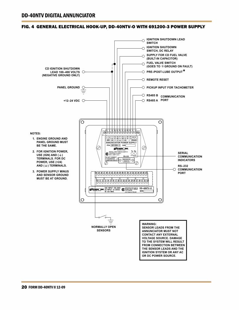
FIG. 4 GENERAL ELECTRICAL HOOK-UP, DD-40NTV-O WITH 691200-3 POWER SUPPLY
IGNITION SHUTDOWN LEADSWITCHIGNITION SHUTDOWNSWITCH, DC RELAYSUPPLY FOR CD FUEL VALVE(BUILT-IN CAPACITOR)FUEL VALVE SWITCH(GOES TO GROUND ON FAULT)
PRE-/POST-LUBE OUTPUT*REMOTE RESET
PICKUP INPUT FOR TACHOMETER
RS485 B COMMUNICATIONRS485 A PORT
CD IGNITION SHUTDOWNLEAD 100–400 VOLTS
(NEGATIVE GROUND ONLY)
PANEL GROUND
+12–24 VDC
NOTES:
1. ENGINE GROUND AND PANEL GROUND MUST BE THE SAME.
2. FOR IGNITION POWER, USE (IGN) AND ( ) TERMINALS. FOR DC POWER, USE (+24) AND ( ) TERMINALS.
3. POWER SUPPLY MINUS AND SENSOR GROUND MUST BE AT GROUND.
SERIALCOMMUNICATIONINDICATORS
RS–232COMMUNICATIONPORT
NORMALLY OPENSENSORS
WARNING:SENSOR LEADS FROM THE ANNUNCIATOR MUST NOT CONTACT ANY EXTERNAL VOLTAGE SOURCE. DAMAGE TO THE SYSTEM WILL RESULT FROM CONNECTION BETWEEN THE SENSOR LEADS AND THE IGNITION SYSTEM OR ANY AC OR DC POWER SOURCE.

www.altronicinc.com 21
DD-40NTV DIGITAL ANNUNCIATOR
FIG. 5 GENERAL ELECTRICAL HOOK-UP, DD-40NTV-U WITH 691200-3 POWER SUPPLY
IGNITION SHUTDOWN LEADSWITCHIGNITION SHUTDOWNSWITCH, DC RELAYSUPPLY FOR CD FUEL VALVE(BUILT-IN CAPACITOR)FUEL VALVE SWITCH(GOES TO GROUND ON FAULT)
PRE-/POST-LUBE OUTPUT*REMOTE RESET
PICKUP INPUT FOR TACHOMETER
RS485 B COMMUNICATIONRS485 A PORT
CD IGNITION SHUTDOWNLEAD 100–400 VOLTS
(NEGATIVE GROUND ONLY)
PANEL GROUND
+12–24 VDC
NOTES:
1. ENGINE GROUND AND PANEL GROUND MUST BE THE SAME.
2. FOR IGNITION POWER, USE (IGN) AND ( ) TERMINALS. FOR DC POWER, USE (+24) AND ( ) TERMINALS.
3. N.O. SENSOR SWITCH MUST HAVE JUMPER IN PLACE BETWEEN TOP ROW AND BOTTOM ROW OF TERMINAL BLOCK. POWER SUPPLY MINUS AND SENSOR GROUND MUST BE AT GROUND.
4. N.C. SENSOR SWITCH, REMOVE JUMPER AND PLACE SWITCH WIRES, ONE IN TOP ROW, OTHER IN BOTTOM ROW.
5. ALL UNUSED INPUTS MUST HAVE JUMPER WIRE IN PLACE.
SERIALCOMMUNICATIONINDICATORS
RS–232COMMUNICATIONPORT
WARNING:SENSOR LEADS FROM THE ANNUNCIATOR MUST NOT CONTACT ANY EXTERNAL VOLTAGE SOURCE. DAMAGE TO THE SYSTEM WILL RESULT FROM CONNECTION BETWEEN THE SENSOR LEADS AND THE IGNITION SYSTEM OR ANY AC OR DC POWER SOURCE.
NORMALLY OPENSENSORS
NORMALLY CLOSEDSENSORS
N/OSWITCH
N/CSWITCH
UNUSEDOUTPUT NON-INCENDIVE
FIELD WIRING ONLY
10 11 12 13 14 15 16 17 20 21 22 23 24 25 26 27 30 31 32 33 C
UU.S. Patent 6,738,
FORM DD-40NTV II 12-0922
DD-40NTV DIGITAL ANNUNCIATOR
TE
ST:
DIS
AB
LES
OU
TPU
TS F
OR
SEN
SOR
TES
T (R
EAD
S 8X
WH
ILE
TE
ST K
EY IS
HEL
D F
OR
BAT
TERY
TES
T
ST
OP:
A
CTI
VATE
S O
UTP
UT
SWIT
CH
ES
R
ESET
: C
LEA
RS
TIM
ERS
AN
D O
UTP
UT
SWIT
CH
ES
TI
MER
1:
CLA
SS B
1 TI
ME
TI
MER
2:
CLA
SS B
2 TI
ME
PR
OG
M M
OD
E:
SELE
CTI
ON
FO
R IN
PUTS
(SEE
SEC
TIO
N 4
.0)
R
PM P
RO
GM
1:
PPR
(PU
LSES
PER
REV
OLU
TIO
N)
R
PM P
RO
GM
2:
RPM
OVE
RSP
EED
RPM
PR
OG
M 1
2:
RPM
UN
DER
SPEE
D
1
PRO
GM
: PR
E-LU
BE
TIM
E
2
PRO
GM
: PO
ST-L
UB
E TI
ME
TIM
ER P
RO
GM
2:
TIM
E D
ELAY
FO
R S
DI A
ND
OU
TPU
T SW
ITC
H 2
O
UTP
UT
SW1:
C
ON
FIG
UR
ES O
UTP
UT
SWIT
CH
1 F
OR
NO
RM
ALL
Y-O
PEN
OR
NO
RM
ALL
Y-C
LOSE
D C
ON
TAC
TS
O
UTP
UT
SW2:
C
ON
FIG
UR
ES O
UTP
UT
SWIT
CH
2 F
OR
NO
RM
ALL
Y-O
PEN
OR
NO
RM
ALL
Y-C
LOSE
D C
ON
TAC
TS
PR
OG
M:
A 23
2 O
R A
485
=> A
SCII
SER
IAL
CO
MM
UN
ICAT
ION
S
23
2 O
R 4
85 =>
MO
DB
US
RTU
SER
IAL
CO
MM
UN
ICAT
ION
S
N
ON
E =>
PIC
K F
OR
IGN
ITIO
N P
OW
ERED
, NO
SER
IAL
CO
MM
UN
ICAT
ION
S
B
AU
D R
ATE
<= S
ELEC
T EI
THER
960
0 O
R 3
8.4K
BA
UD
PR
OG
M:
NO
DE
NU
MB
ER (N
OT
REQ
UIR
ED F
OR
NO
N-S
ERIA
L A
PPLI
CAT
ION
S)
H
OU
RS:
R
ESET
OR
PR
ESET
HO
UR
S
TY
PE:
3 FO
R P
OW
ER S
UPP
LY 6
9120
0-3,
1 F
OR
PO
WER
SU
PPLY
691
200-
1
N
OTE
: D
ASH
ED L
INES
, USE
O
R
AR
RO
W K
EYS
TO C
HA
NG
E
FIG. 6A FLOWCHART WITH 691200-3 POWER SUPPLY
www.altronicinc.com 23
DD-40NTV DIGITAL ANNUNCIATOR
TE
ST:
DIS
AB
LES
OU
TPU
TS F
OR
SEN
SOR
TES
T (R
EAD
S 8X
WH
ILE
TE
ST K
EY IS
HEL
D F
OR
BAT
TERY
TES
T
ST
OP:
A
CTI
VATE
S O
UTP
UT
SWIT
CH
ES
R
ESET
: C
LEA
RS
TIM
ERS
AN
D O
UTP
UT
SWIT
CH
ES
TI
MER
1:
CLA
SS B
1 TI
ME
TI
MER
2:
CLA
SS B
2 TI
ME
PR
OG
M M
OD
E:
SELE
CTI
ON
FO
R IN
PUTS
(SEE
SEC
TIO
N 4
.0)
R
PM P
RO
GM
1:
PPR
(PU
LSES
PER
REV
OLU
TIO
N)
R
PM P
RO
GM
2:
RPM
OVE
RSP
EED
TIM
ER P
RO
GM
2:
TIM
E D
ELAY
FO
R S
DI A
ND
OU
TPU
T SW
ITC
H 2
O
UTP
UT
SW1:
C
ON
FIG
UR
ES O
UTP
UT
SWIT
CH
1 F
OR
NO
RM
ALL
Y-O
PEN
OR
NO
RM
ALL
Y-C
LOSE
D C
ON
TAC
TS
O
UTP
UT
SW2:
C
ON
FIG
UR
ES O
UTP
UT
SWIT
CH
2 F
OR
NO
RM
ALL
Y-O
PEN
OR
NO
RM
ALL
Y-C
LOSE
D C
ON
TAC
TS
PR
OG
M:
A 23
2 O
R A
485
=> A
SCII
SER
IAL
CO
MM
UN
ICAT
ION
S
23
2 O
R 4
85 =>
MO
DB
US
RTU
SER
IAL
CO
MM
UN
ICAT
ION
S
N
ON
E =>
PIC
K F
OR
IGN
ITIO
N P
OW
ERED
, NO
SER
IAL
CO
MM
UN
ICAT
ION
S
PR
OG
M:
NO
DE
NU
MB
ER (N
OT
REQ
UIR
ED F
OR
NO
N-S
ERIA
L A
PPLI
CAT
ION
S)
H
OU
RS:
R
ESET
OR
PR
ESET
HO
UR
S
TY
PE:
3 FO
R P
OW
ER S
UPP
LY 6
9120
0-3,
1 F
OR
PO
WER
SU
PPLY
691
200-
1
N
OTE
: D
ASH
ED L
INES
, USE
O
R
AR
RO
W K
EYS
TO C
HA
NG
E
FIG. 6B FLOWCHART WITH 691200-1 POWER SUPPLY

FORM DD-40NTV II 12-0924
DD-40NTV DIGITAL ANNUNCIATOR
FIG. 7 WIRING DIAGRAM: CD IGNITION AND CD FUEL VALVE
RS–232DO NOT CONNECTIF HAZARDOUSCONDITION EXISTS
Tx Rx
P/N 691200–3 S/N
GIRARD, OHIOINSTALL PER FORM DD-40NTV IICERTIFIED CLASS I,DIV 2, GRP C & D
ANNUNCIATOR POWER SUPPLY24V
IGN
B A
RS485
PU
RR
LUB
SW1
FVA
SW2
SDI
+ IG SD S2 FV S1 LB RR PU B A
NOTE:CONNECT GROUND DIRECTLYTO THE PANEL OR ENGINEGROUND. DO NOT CONNECTTO THE IGNITION SYSTEMCOMMON COIL GROUND.
3 8 MURPHY M50-CDREMOVE ALL JUMPERS. DO NOT GROUND #5 TERMINAL. CONNECTONLY TO COIL LEADS AS SHOWN.PNEUMATIC SYSTEM
690019SOLENOIDVALVE
ALTRONIC690040-1
AC/DC CONTROL
FUEL VALVE
FUEL VALVE
E C B D S
MURPHY221-PH-CD
IGNITIONSHUTDOWN
LEAD
1 2
CAUTION: LUB TERMINAL (8TH FROM LEFT) REPLACES RPM TERMINAL ON THE 691200-1 POWER SUPPLY. IF REPLACING A 691200-1 POWER SUPPLY WITH 691200-3, REMOVE THE JUMPER BETWEEN THE 3RD AND 8TH (FROM LEFT) TERMINALS AND DIS-CARD. REFER TO INSTRUCTIONS DD-NTS II 5-02 FOR WIRING DETAILS USING A 691200-1 POWER SUPPLY.
www.altronicinc.com 25
DD-40NTV DIGITAL ANNUNCIATOR
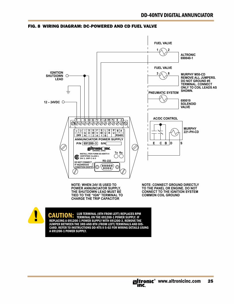
FIG. 8 WIRING DIAGRAM: DC-POWERED AND CD FUEL VALVE
RS–232DO NOT CONNECTIF HAZARDOUSCONDITION EXISTS
Tx Rx
P/N 691200–3 S/N
GIRARD, OHIOINSTALL PER FORM DD-40NTV IICERTIFIED CLASS I,DIV 2, GRP C & D
ANNUNCIATOR POWER SUPPLY24V
IGN
B A
RS485
PU
RR
LUB
SW1
FVA
SW2
SDI
+ IG SD S2 FV S1 LB RR PU B A
3 8 MURPHY M50-CDREMOVE ALL JUMPERS. DO NOT GROUND #5 TERMINAL. CONNECTONLY TO COIL LEADS AS SHOWN.PNEUMATIC SYSTEM
690019SOLENOIDVALVE
ALTRONIC690040-1
AC/DC CONTROL
FUEL VALVE
FUEL VALVE
E C B D S
MURPHY221-PH-CD
IGNITIONSHUTDOWN
LEAD
12 – 24VDC
1 2
CAUTION: LUB TERMINAL (8TH FROM LEFT) REPLACES RPM TERMINAL ON THE 691200-1 POWER SUPPLY. IF REPLACING A 691200-1 POWER SUPPLY WITH 691200-3, REMOVE THE JUMPER BETWEEN THE 3RD AND 8TH (FROM LEFT) TERMINALS AND DIS-CARD. REFER TO INSTRUCTIONS DD-NTS II 5-02 FOR WIRING DETAILS USING A 691200-1 POWER SUPPLY.
NOTE: WHEN 24V IS USED TO POWER ANNUNCIATOR SUPPLY, THE SHUTDOWN LEAD MUST BE TIED TO THE “IGN” TERMINAL TO CHARGE THE TRIP CAPACITOR
NOTE: CONNECT GROUND DIRECTLY TO THE PANEL OR ENGINE. DO NOT CONNECT TO THE IGNITION SYSTEM COMMON COIL GROUND
FORM DD-40NTV II 12-0926
DD-40NTV DIGITAL ANNUNCIATOR
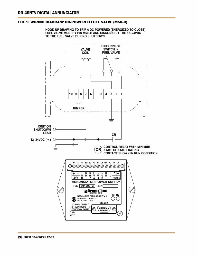
FIG. 9 WIRING DIAGRAM: DC-POWERED FUEL VALVE (M50-B)
RS–232DO NOT CONNECTIF HAZARDOUSCONDITION EXISTS
Tx Rx
P/N 691200–3 S/N
GIRARD, OHIOINSTALL PER FORM DD-40NT V IICERTIFIED CLASS I,DIV 2, GRP C & D
ANNUNCIATOR POWER SUPPLY24V
IGN
B A
RS485
PU
RR
LUB
SW1
FVA
SW2
SDI
+ IG SD S2 FV S1 LB RR PU B A
IGNITIONSHUTDOWN
LEAD
12–24VDC ( + )
VALVECOIL
JUMPER
CR
CR
DISCONNECTSWITCH IN
FUEL VALVE
CONTROL RELAY WITH MINIMUM3 AMP CONTACT RATINGCONTACT SHOWN IN RUN CONDITION
10 9 8 7 6 5 4 3 2 1
HOOK-UP DRAWING TO TRIP A DC-POWERED (ENERGIZED TO CLOSE)FUEL VALVE MURPHY P/N M50–B AND DISCONNECT THE 12–24VDCTO THE FUEL VALVE DURING SHUTDOWN.

www.altronicinc.com 27
DD-40NTV DIGITAL ANNUNCIATOR
FIG. 10 WIRING DIAGRAM: DC-POWERED FUEL VALVE
MURPHYM50-FS
COIL
ALTRONIC690040-2
COIL
1 2 5 4
RS–232DO NOT CONNECTIF HAZARDOUSCONDITION EXISTS
Tx Rx
P/N 691200–3 S/N
GIRARD, OHIOINSTALL PER FORM DD-40NT V IICERTIFIED CLASS I,DIV 2, GRP C & D
ANNUNCIATOR POWER SUPPLY24V
IGN
B A
RS485
PU
RR
LUB
SW1
FVA
SW2
SDI
+ IG SD S2 FV S1 LB RR PU B A
IGNITIONSHUTDOWN
LEAD
12–24VDC ( + )
HOOK-UP DRAWING TO TRIP A DC-POWERED (ENERGIZED TO RUN) FUEL VALVE BY OPENING SW1(THE FUEL VALVE SWITCH) DURING SHUTDOWN.
FORM DD-40NTV II 12-0928
DD-40NTV DIGITAL ANNUNCIATOR
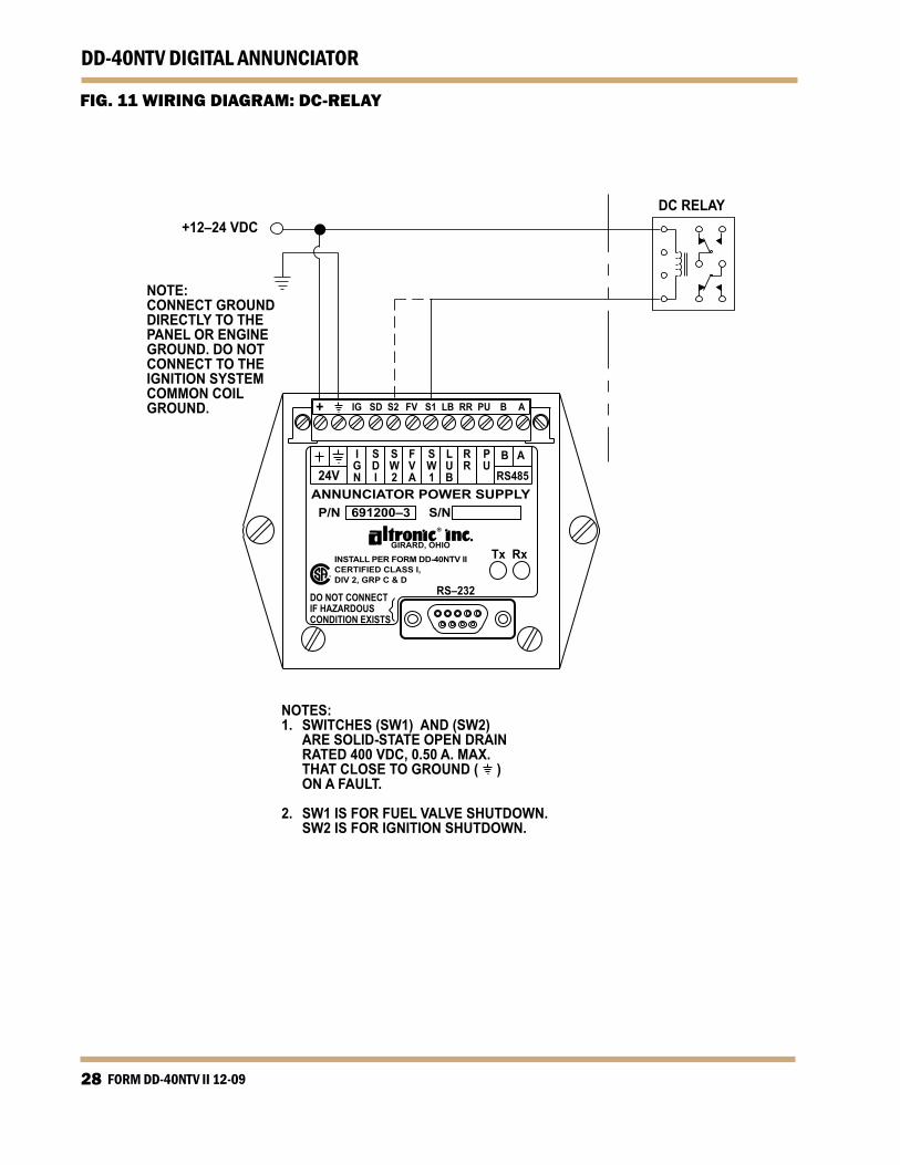
FIG. 11 WIRING DIAGRAM: DC-RELAY
NOTES:1. SWITCHES (SW1) AND (SW2) ARE SOLID-STATE OPEN DRAIN RATED 400 VDC, 0.50 A. MAX. THAT CLOSE TO GROUND ( ) ON A FAULT.
2. SW1 IS FOR FUEL VALVE SHUTDOWN. SW2 IS FOR IGNITION SHUTDOWN.
RS–232DO NOT CONNECTIF HAZARDOUSCONDITION EXISTS
Tx Rx
P/N 691200–3 S/N
GIRARD, OHIOINSTALL PER FORM DD-40NTV IICERTIFIED CLASS I,DIV 2, GRP C & D
ANNUNCIATOR POWER SUPPLY24V
IGN
B A
RS485
PU
RR
LUB
SW1
FVA
SW2
SDI
+ IG SD S2 FV S1 LB RR PU B A
+12–24 VDC
NOTE:CONNECT GROUNDDIRECTLY TO THEPANEL OR ENGINEGROUND. DO NOTCONNECT TO THEIGNITION SYSTEMCOMMON COILGROUND.
DC RELAY

www.altronicinc.com 29
DD-40NTV DIGITAL ANNUNCIATOR
RS–232DO NOT CONNECTIF HAZARDOUSCONDITION EXISTS
Tx Rx
P/N 691200–3 S/N
GIRARD, OHIOINSTALL PER FORM DD-40NTV IICERTIFIED CLASS I,DIV 2, GRP C & D
ANNUNCIATOR POWER SUPPLY24V
IGN
B A
RS485
PU
RR
LUB
SW1
FVA
SW2
SDI
+ IG SD S2 FV S1 LB RR PU B A
RS–232DO NOT CONNECTIF HAZARDOUSCONDITION EXISTS
Tx Rx
P/N 691200–3 S/N
GIRARD, OHIO
INSTALL PER FORM DD-40NTV IICERTIFIED CLASS I,DIV 2, GRP C & D
ANNUNCIATOR POWER SUPPLY24V
IGN
B A
RS485
PU
RR
LUB
SW1
FVA
SW2
SDI
+ IG SD S2 FV S1 LB RR PU B A
+12–24 VDC
IGNITIONSHUTDOWNLEAD
PANELGROUND
+12–24 VDCDC RELAY
LUBEMOTOR
NOTE: “LUB” IS A SOLID-STATE, N/O
SWITCH, RATED AT 400 VDC, 0.50 A. MAX., THAT CLOSES TO GROUND ( ) ON A STOP, FAULT, OR PRE-LUBE/POST-LUBE CONDITION.
(OPENS AFTER PRE/POST-LUBE TIMERS EXPIRE)
NOTE: CONNECT ( ) TERMINAL TO
PANEL GROUND. PANEL GROUND SHOULD BE THE SAME AS ENGINE GROUND. DO NOT CONNECT DIRECTLY TO THE IGNITION SYSTEM COMMON COIL GROUND. CONNECT SHUTDOWN LEAD TO THE (IGN) TERMINAL FOR ANNUN-CIATOR POWER.
FIG. 12 WIRING DIAGRAM: TACH INPUT, NEG GROUND CD IGN SHUTDOWN LEAD INPUT
FIG. 13 WIRING DIAGRAM: PRE-/POST-LUBE MOTOR*

FORM DD-40NTV II 12-0930
DD-40NTV DIGITAL ANNUNCIATOR
+12–24 VDCPOWER INPUT
50 mA MAX.
CABLE ASSEMBLYP/N 693104 SERIES
MAGNETIC PICKUPP/N 691118 SERIES
TYPICALLY8 TO 20 PITCH GEAR
TYP. .005" / .020"
+12–24 VDCPOWER INPUT50 mA MAX.
10KΩ1/2 WATTRESISTOR
+5 VDC50 mA MAX.
CABLE ASSEMBLYP/N 593050 SERIES
HALL-EFFECTPICKUPP/N 791050SERIES
CBA
NORTH POLE OF MAGNETMUST FACE PICKUP
TYP. .030" / .040"
24VIGN
B A
RS485
PU
RR
LUB
SW1
FVA
SW2
SDI
+ IG SD S2 FV S1 LB RR PU B A
24VIGN
B A
RS485
PU
RR
LUB
SW1
FVA
SW2
SDI
+ IG SD S2 FV S1 LB RR PU B A
FIG. 14 WIRING DIAGRAM: MAGNETIC PICKUP TACHOMETER INPUT
FIG. 15 WIRING DIAGRAM: HALL-EFFECT PICKUP TACHOMETER INPUT

www.altronicinc.com 31
DD-40NTV DIGITAL ANNUNCIATOR
FIG. 16 WIRING DIAGRAM: REMOTE RESET
RS–232DO NOT CONNECTIF HAZARDOUSCONDITION EXISTS
Tx Rx
P/N 691200–3 S/N
GIRARD, OHIO
INSTALL PER FORM DD-40NTV IICERTIFIED CLASS I,DIV 2, GRP C & D
ANNUNCIATOR POWER SUPPLY24V
IGN
B A
RS485
PU
RR
LUB
SW1
FVA
SW2
SDI
+ IG SD S2 FV S1 LB RR PU B A
PANELGROUND
NOTE: USE A MOMENTARY PUSH-BUTTON OR RELAY FOR REMOTE RESET. MAKE SURE REMOTE RESET IS OPEN DURING ENGINE OPERATION.

FORM DD-40NTV II 12-0932
DD-40NTV DIGITAL ANNUNCIATOR
FIG. 17 WIRING DIAGRAM: RS-485 COMMUNICATIONS
NOTE: CONNECT A 120Ω RESISTOR BETWEEN RS-485 “A” AND RS-485 “B” TERMINALS AT THE POWER SUPPLY MODULE FOR WIRE RUNS GREATER THAN 500 FEET TOTAL.
SERIALCOMMUNICATIONINDICATORS
RS–232DO NOT CONNECTIF HAZARDOUSCONDITION EXISTS
Tx Rx
P/N 691200–3 S/N
GIRARD, OHIO
INSTALL PER FORM DD-40NTS IICERTIFIED CLASS I,DIV 2, GRP C & D
ANNUNCIATOR POWER SUPPLY24V
IGN
B A
RS485
PU
RR
LUB
SW1
FVA
SW2
SDI
+ IG SD S2 FV S1 LB RR PU B A
PC or PLCRS-485 “A”RS-485 “B”
NOTES:1. USE SHIELDED CABLE FOR RS-485 CONNECTIONS. CONNECT SHIELD AT PC OR PLC ONLY.
2. EACH UNIT MUST HAVE A UNIQUE NODE NUMBER. MAXIMUM 32 NODES.
3. TO MINIMIZE UNWANTED REFLECTIONS ON THE RS-485 LINE, THE WIRES SHOULD BE HOOKED-UP FROM ONE INSTRUMENT TO THE NEXT IN A DAISYCHAIN FORMAT.
www.altronicinc.com 33
DD-40NTV DIGITAL ANNUNCIATOR
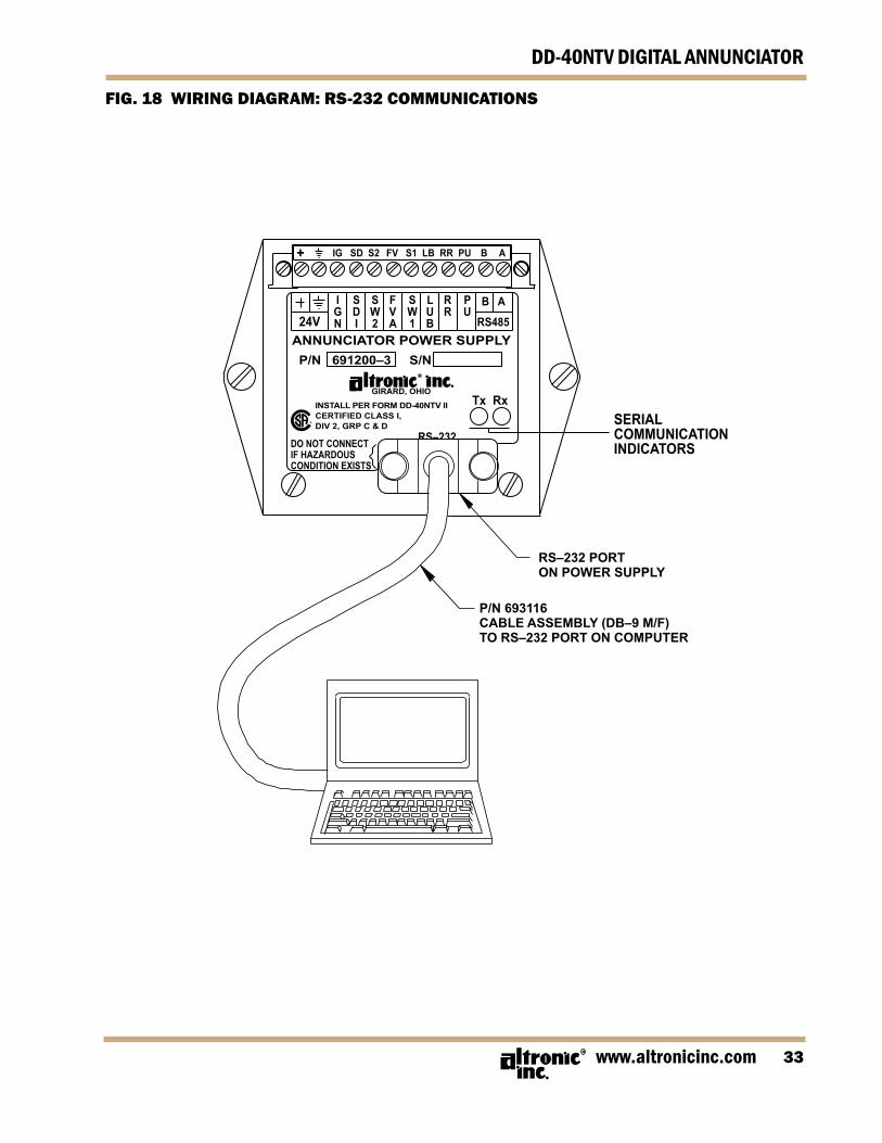
FIG. 18 WIRING DIAGRAM: RS-232 COMMUNICATIONS
SERIALCOMMUNICATIONINDICATORS
RS–232 PORTON POWER SUPPLY
P/N 693116CABLE ASSEMBLY (DB–9 M/F)TO RS–232 PORT ON COMPUTER
DO NOT CONNECTIF HAZARDOUSCONDITION EXISTS
Tx Rx
P/N 691200–3 S/N
GIRARD, OHIOINSTALL PER FORM DD-40NTV IICERTIFIED CLASS I,DIV 2, GRP C & D
ANNUNCIATOR POWER SUPPLY24V
IGN
B A
RS485
PU
RR
LUB
SW1
FVA
SW2
SDI
+ IG SD S2 FV S1 LB RR PU B A
RS–232

FORM DD-40NTV II 12-0934
DD-40NTV DIGITAL ANNUNCIATOR
FIG. 19 WIRING DIAGRAM: NULL MODEM CABLE
RS–232 NULL MODEM CABLE. USE TO CONNECT THE DD-40NTV-OANNUNCIATOR SYSTEM TO AN EXTERNAL MODEM. CONNECTION INTHIS MANNER ELIMINATES THE NEED FOR A NULL MODEM ADAPTER.
PINS NOT LISTED ARE NOT USED FOR THIS APPLICATIONAND ARE LEFT OPEN.
ACCEPTABLE CABLES FOR RS–232 APPLICATIONS:
9534, 9536, BELDEN 4 OR 6 CONDUCTOR
9609, 9611 BELDEN 4 OR 6 CONDUCTOR (LOW CAPACITANCE)
9927, 9931 BELDEN 4 OR 6 CONDUCTOR (LOW CAPACITANCE)
FOR OTHER ACCEPTABLE CABLES SEE BELDEN OR OTHERMANUFACTURER’S CATALOGS.
DB–9 (MALE)9–PIN CONNECTORANNUNCIATOR
DB–25 (MALE)25–PIN CONNECTOR(MODEM)
(RECEIVE DATA)
(TRANSMIT DATA)
(CLEAR TO SEND)
CABLE SHIELD FG
(TRANSMIT DATA) TD
(RECEIVE DATA) RD
SG
(REQUEST TO SEND) RTS
PINNUMBER
1
2
3
7
4
1
2
3
5
6
8
DCD
RD
TD
SG
DSR
CTS
PINNUMBER
SIGNAL GROUND

www.altronicinc.com 35
DD-40NTV DIGITAL ANNUNCIATOR
FIG. 20 WIRING DIAGRAM: RS-485 COMMUNICATIONS TO EXTERNAL MODEM
RS–2
32DO
NOT
CON
NECT
IF H
AZAR
DOUS
COND
ITIO
N EX
ISTS
Tx R
x
P/N
69
1200
–3
S/N
GIR
AR
D, O
HIO
INST
ALL
PER
FO
RM
DD
-40N
TV II
CE
RTI
FIE
D C
LAS
S I,
DIV
2, G
RP
C &
D
AN
NU
NC
IATO
R P
OW
ER
SU
PP
LY24
VI G N
B A
RS48
5
P UR R
L U B
S W 1
F V A
S W 2
S D I
+
IG
SD S
2 F
V S
1 L
B R
R P
U B
A
NOTE
S:
1. E
ACH
UNIT
IN T
HE R
S-48
5 CO
MM
UNIC
ATIO
N SY
STEM
MUS
T BE
PRO
GRA
MM
ED W
ITH
A UN
IQUE
NO
DE N
UMBE
R.
2.
REF
ER T
O IN
STAL
LATI
ON
INST
RUCT
IONS
AN
D M
ODE
M U
SER’
S G
UIDE
AND
REF
ER-
ENCE
MAN
UAL
TO C
ONF
IGUR
E M
ODE
M.
3.
RS-
485
TO R
S-23
2 CO
NVER
TER
ADAM
-452
0 FR
OM
ADV
ANTE
CH A
MER
ICA
EXTE
RNAL
MO
DEM
MO
UNTE
D NE
AR P
HONE
LIN
EIN
CO
NTRO
L RO
OM
(TYP
ICAL
MO
DEM
TEM
P.RA
NGE
0°C
TO 5
0°C)
ADAM
–452
0RS
–232
TO
RS–4
85CO
NVER
TER
AC POW
ER
DB–9
MAL
E TO
DB–2
5 M
ALE
CABL
E
10–3
0 VD
C +
1.4
WAT
TS –
UNIT
1
MUL
TIPL
E RS
–485
CO
MM
UNIC
ATIO
N SY
STEM
S
UNIT
2A
B
SA
B
S
UNIT
3
PHO
NE J
ACK
PHO
NEJA
CK
PHO
NE L
INE
TO IN
TERN
ALM
ODE
M
REM
OTE
PC
WIT
HIN
TERN
AL M
ODE
M
DATA
+DA
TA –
+VS
GND
NOTE
: A
LOW
-CAP
ACIT
ANCE
INDU
STRI
AL
SHIE
LDED
CAB
LE S
HOUL
D BE
USE
D.
EXTE
RNAL
MO
DEM
9600
OR
38.4
K BA
UD8
DATA
BIT
S1
STO
P BI
TNO
PAR
ITY

FORM DD-40NTV II 12-0936
DD-40NTV DIGITAL ANNUNCIATOR
FIG. 21 WIRING DIAGRAM: RS-232 COMMUNICATIONS TO EXTERNAL MODEM
NOTE
S:
1.
REF
ER T
O IN
STAL
LATI
ON
INST
RUCT
IONS
AND
M
ODE
M U
SER’
S G
UIDE
AND
REF
EREN
CE
MAN
UAL
TO C
ONF
IGUR
E M
ODE
M.
3.
A N
ULL
MO
DEM
CAB
LE C
AN B
E US
ED IN
STEA
D O
F TH
E NU
LL M
ODE
M A
DAPT
ER IF
DES
IRED
.EX
TERN
AL M
ODE
MM
OUN
TED
NEAR
PHO
NE L
INE
IN C
ONT
ROL
ROO
M(T
YPIC
AL M
ODE
M T
EMP.
RAN
GE
0°C
TO 5
0°C)
DD-4
0NTV
-O A
NNUN
CIAT
OR
SYST
EMM
OUN
TED
IN P
ANEL
RS–2
32 S
TAND
ARD
MAX
.CA
BLE
LENG
TH 5
0 FT
.FO
R BE
ST R
ESUL
TS, A
N IN
DUST
RIAL
SHIE
LDED
CAB
LE S
HOUL
D BE
USE
D
NULL
MO
DEM
ADA
PTER
TYPI
CAL:
RAD
IO S
HACK
CAT.
NO
. 26–
1496
B
NOTE
: FO
R EX
TEND
ED D
ISTA
NCES
,A
LOW
-CAP
ACIT
ANCE
INDU
STRI
ALSH
IELD
ED C
ABLE
SHO
ULD
BE U
SED.
RS–2
32 P
ORT
MAL
E DB
–9 C
ONN
ECTO
RRE
QUI
RED
ON
CABL
ES/
N
AC POW
ER
DB–9
MAL
E TO
DB–
25
MAL
E CA
BLE
PHO
NE J
ACK
PHO
NEJA
CK
PHO
NE L
INE
TO IN
TERN
ALM
ODE
M
REM
OTE
PC
WIT
HIN
TERN
AL M
ODE
M
GIR
AR
D, O
HIO
EXTE
RNAL
MO
DEM
9600
OR
38.4
K BA
UD8
DATA
BIT
S1
STO
P BI
TNO
PAR
ITY