installation instructions -...
TRANSCRIPT
CALOWAMB018A00 –CALOWAMB023A00CALOWAMB037A00--CALOWAMB042A00
Installation Instructions
SPLIT SYSTEM AC UNITSACCESSORY MOTORMASTERR IHEAD PRESSURE CONTROLLER
15 & 20 TONS
IMPORTANT: Read these instructions completely beforeattempting to install this accessory.
SAFETY CONSIDERATIONSInstallation, start--up and servicing of this equipment canbe hazardous due to system pressures, electricalcomponents and equipment location (roofs, elevatedstructures, etc.)Untrained personnel can perform the basic maintenancefunctions. All other operations should be performed bytrained service personnel. When working onair--conditioning equipment, observe precautions in theliterature, tags and labels attached to the unit, and othersafety precautions that may apply.Follow all safety codes. Wear safety glasses and workgloves.Recognize safety information. This is the safety--alert
symbol . When you see this symbol on the unit and ininstructions or manuals, be alert to the potential forpersonal injury.Understand the signal words DANGER, WARNING, andCAUTION. These words are used with the safety--alertsymbol. DANGER identifies the most serious hazardswhich will result in severe personal injury or death.WARNING signifies a hazard which could result inpersonal injury or death. CAUTION is used to identifyunsafe practices which may result in minor personalinjury or product and property damage. NOTE is used tohighlight suggestions which will result in enhancedinstallation, reliability, or operation.
ELECTRICAL SHOCK HAZARD
Failure to follow this warning could cause personalinjury or death.
Before performing service or maintenanceoperations on unit, turn off main power switch tounit and install lockout tag. Ensure electrical serviceto rooftop unit agrees with voltage and amperagelisted on the unit rating plate.
! WARNING
EQUIPMENT DAMAGE HAZARD
Failure to follow this caution may result in damage toequipment.
When removing panels from the unit, be careful not todamage the roof or other surfaces with the panels.
CAUTION!
GENERALMotormaster I solid----state head pressure control regulatesoutdoor (condenser) fan speed during Cooling modeoperation. A temperature sensor, mounted on a returnbend of the outdoor (condenser) coil, controls the speed ofapproved outdoor (condenser) fan motors in order tomaintain a constant head pressure in the outdoor(condenser) coil. When properly installed, the control willmaintain the appropriate head pressure at low ambienttemperatures down to --20_F (--28_C).On size 16/180/181 and 25/240/241 units, the singleMotormaster I control is connected to two outdoor(condenser) fan motors – OFM1 and OFM3. Theadditional fan motors – OFM2 (all units) and OFM4 (size25/240/241 only) ---- are staged off at mild ambienttemperatures (below 40_F (6_C) by low ambienttemperature switch LAS through relay LAR.575--V ONLY: TRANSFORMER WITH 460--VMOTORS AND CONTROL ---- On 575--v units, the575--v motors installed in positions OFM1 and OFM3 arereplaced with 460--v fan motors, powered through astepdown (575--v to 460--v) transformer and controlledthrough a 460--v Motormaster controller.
2
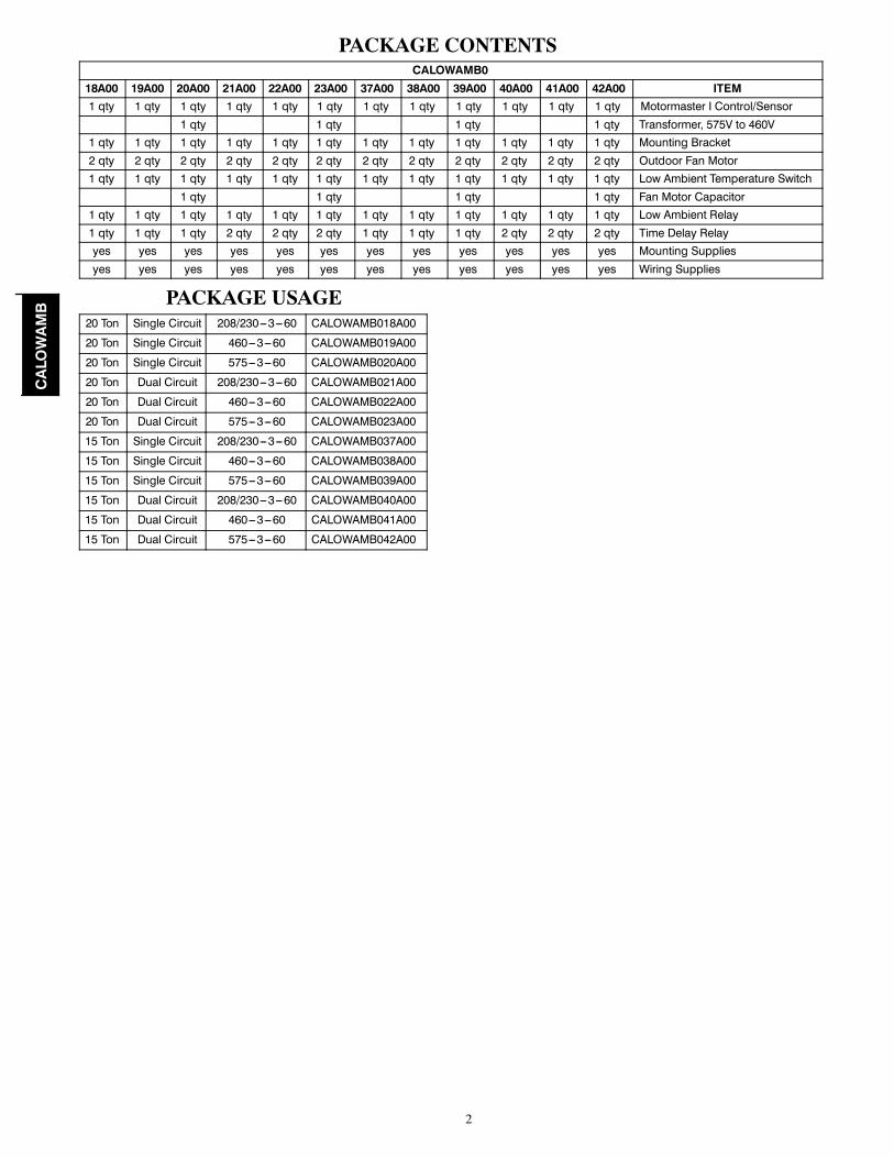
PACKAGE CONTENTSCALOWAMB0
18A00 19A00 20A00 21A00 22A00 23A00 37A00 38A00 39A00 40A00 41A00 42A00 ITEM1 qty 1 qty 1 qty 1 qty 1 qty 1 qty 1 qty 1 qty 1 qty 1 qty 1 qty 1 qty Motormaster I Control/Sensor
1 qty 1 qty 1 qty 1 qty Transformer, 575V to 460V1 qty 1 qty 1 qty 1 qty 1 qty 1 qty 1 qty 1 qty 1 qty 1 qty 1 qty 1 qty Mounting Bracket2 qty 2 qty 2 qty 2 qty 2 qty 2 qty 2 qty 2 qty 2 qty 2 qty 2 qty 2 qty Outdoor Fan Motor1 qty 1 qty 1 qty 1 qty 1 qty 1 qty 1 qty 1 qty 1 qty 1 qty 1 qty 1 qty Low Ambient Temperature Switch
1 qty 1 qty 1 qty 1 qty Fan Motor Capacitor1 qty 1 qty 1 qty 1 qty 1 qty 1 qty 1 qty 1 qty 1 qty 1 qty 1 qty 1 qty Low Ambient Relay1 qty 1 qty 1 qty 2 qty 2 qty 2 qty 1 qty 1 qty 1 qty 2 qty 2 qty 2 qty Time Delay Relayyes yes yes yes yes yes yes yes yes yes yes yes Mounting Suppliesyes yes yes yes yes yes yes yes yes yes yes yes Wiring Supplies
PACKAGE USAGE20 Ton Single Circuit 208/230---3---60 CALOWAMB018A00
20 Ton Single Circuit 460---3---60 CALOWAMB019A00
20 Ton Single Circuit 575---3---60 CALOWAMB020A00
20 Ton Dual Circuit 208/230---3---60 CALOWAMB021A00
20 Ton Dual Circuit 460---3---60 CALOWAMB022A00
20 Ton Dual Circuit 575---3---60 CALOWAMB023A00
15 Ton Single Circuit 208/230---3---60 CALOWAMB037A00
15 Ton Single Circuit 460---3---60 CALOWAMB038A00
15 Ton Single Circuit 575---3---60 CALOWAMB039A00
15 Ton Dual Circuit 208/230---3---60 CALOWAMB040A00
15 Ton Dual Circuit 460---3---60 CALOWAMB041A00
15 Ton Dual Circuit 575---3---60 CALOWAMB042A00
CALOWAMB

3
INSTALLATIONCheck voltage of kit parts against unit voltage. Beforestarting, check controller and motor voltage against unitvoltage.NOTE: 575--v units use 460--v controller and motors withstepdown autotransformer.
Changing outdoor fan motors (all units)1. Disconnect power to the unit. Lock--out/tag--out.2. Remove main access panel and control box cover.3. At capacitor CAP1.4. Disconnect all OFM BLK wires at TB3. Retain theBLK wire to relay OFR.
5. Identify fan--motor positions OFM1 and OFM3; re-fer to Fig. 11 and Fig. 12.
6. Trace the motor leads from OFM1 and OFM3 to thecontrol box. Note wire path into the control box.Pull these leads out of the control box.
7. Remove the screws securing the OFM1 and OFM3fan grilles from the unit top cover. Save thesescrews.
8. Remove the fan grille assemblies at OFM1 andOFM3 by lifting the assemblies straight up until theprop blades clear the fan deck. Invert the grille as-semblies and place on a support surface.
9. Measure and record the dimension of the top edgeof the prop blade to the grille.
10. For OFM1 and OFM3 assemblies. remove the propfan from the motor shaft.
11. Observe the orientation of the fan motor wires at thegrille and motor shell opening. Remove the fanmotors from the grille center plate.
12. Attach the motors from the accessory kit to thegrilles. Do not overtighten the nuts onto the motorthroughbolt ends. Torque. Secure wires to grille asnoted in step 11.
13. Mount the prop fan onto the motor shaft. Locatethe prop at the distance from the grille measured instep 9 above. If the prop blade contacts the motorhousing, adjust prop position until the prop clearsthe motor by 1/2--in. (13 mm). Torque the prop setscrews to in--lbs .
14. Position the OFM1 grille assembly over its top pan-el opening and carefully insert the motor wires andprop though the opening and lower into place. Se-cure using screws removed in step 7. Repeat forOFM3 grille assembly.
15. Rotate the prop fan to ensure there is no interfer-ence or contact with unit piping or motor wiring.
16. Route the motor leads into the control box as notedin step 6.
Motormaster installation (all units) (ref Fig.1.)
1. Locate the mounting plate in the kit and attach tounit side panel per Fig. 1 using the sheet metalscrews included with the accessory.
2. Mount the Motormaster controller onto the mount-ing plate using four screws. The controller must be
mounted vertically with leads at the bottom. To en-sure electrical ground, use the serrated head mount-ing screws provided.
3. Route the Motormaster sensor cord to the Circuit 1coil (right of compressors).
4. Route the RED and BLK wires from the Motormas-ter controller into the unit control box.
5. For 575v units, the supplied transformer (575v to460v) also mounts to the bracket.
Mount LAR relayAccessory packages for these units include an LAR relay.Refer to Component Arrangement view on the unit wiringdiagram; mount the relay in the unit control box in LARposition using screws provided.
Mount Fan Staging Temperature Switch andWire (all units)
1. Mount the low ambient fan staging temperatureswitch (LAS) to the top of the service valve housing(see Fig. 2).
2. Connect one of the YEL (LAS) wires to Y1 on theconnection board (TB) and connect the other YELwire to terminal 1 of the low ambient relay (LAR).See Fig. 3--6 fo details, depending on unit type andvoltage.
3. Route YEL wires into unit control box.
Control Box Changes and WiringRefer to Component Location view on unit wiring label todetermine location in control box for new components.
575--units: Replace CAP11. Disconnect the YEL wire at CAP1 center terminal.2. Unscrew the capacitor strap at CAP1 carefully sothat it can be reused.
3. Remove the capacitor and store it in a safe place ordiscard properly.
4. Using the capacitor strap, safely secure the new10mfdx10mfd capacitor in the original capacitorlocation.
5. Reconnect the YEL wire at the capacitor center ter-minal.
CALOWAMB

4
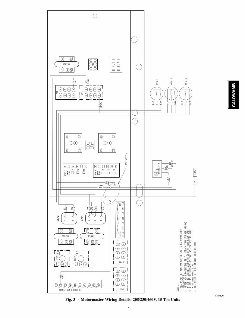
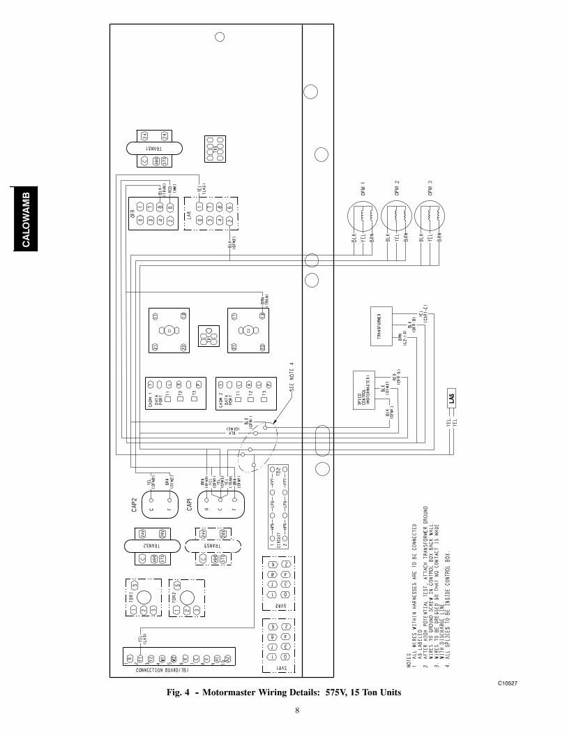
Wiring ConnectionsMotormaster/OFM1/OFM3/OFR Wiring
1. Rewire unit for new or replaced parts using the pro-vided wiring diagrams (see Fig. 3--6) and the unitlabel wiring diagram for details.
2. Locate the YEL and BRN leads from new OFM1and OFM3; pull to capacitor CAP1.
3. Connect both YEL leads at CAP1 terminal C.4. Connect BRN lead from OFM1 at CAP1 terminal F.5. Connect BRN lead from OFM3 at CAP1 terminalH.
Sensor LocationUnit with Copper Tube CoilSensor is attached to a transfer header tube on Circuit 1coil, located to the right of the compressors. Refer toFigures for specific tube location. Use machine screwand nut to secure sensor clamp to the tube.
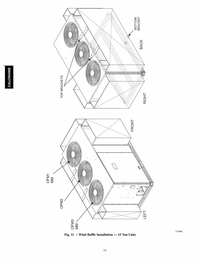
Wind BafflesWind baffles are required to prevent wind cross currentsfrom causing abnormally low condensing temperatures.
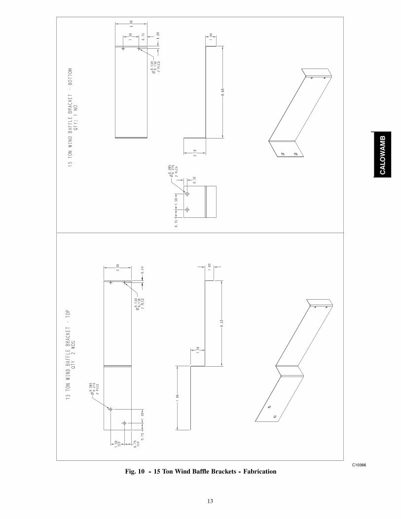
Use 20----gauge sheet metal to fabricate wind baffles (seeFig. 9 and Table 1) and mounting brackets (see Fig. 10).NOTE: Mounting brackets are for use on 15 ton unitsonly.
Install the wind baffles as show in Fig. 11, for 15 ton unitsand Fig. 12, for 20 ton units.
6. Reconnect power to the unit.7. Mount the supplied time delay relay(s) (TDR) in thecontrol box. See Fig. 7 & 8 for location(s).
8. Rewire unit for the new or replaced parts (outdoorfan motors, Motormaster control, plus time delayrelays, low ambient relay, low ambient temperatureswitch and 575 to 460V transformer, as applicable).Use the provided wiring diagrams (see Fig. 3--6)and the unit label wiring diagram for details.
NOTE: The 575V to 460V transformer (HT01AH858) isused as an auto----transformer (buck boost transformer),not as a traditional step down isolation transformertherefore it must be wired as per Fig. 4 (15 ton units) orFig. 6 (20 ton units).
9. Coil up all excess wire and secure it next to the con-troller.
CALOWAMB

5
15 Ton 208/230 & 460V 15 Ton 575V
MountingBracket
Low AmbientTemperatureSwitch
Transformer575V to 460V
Motormaster 1
MountingBracket
Motormaster 1
Low AmbientTemperatureSwitch
20 Ton 208/230 & 460V 20 Ton 575V
MountingBracket
Low AmbientTemperatureSwitch
Transformer575V to 460V
Motormaster 1
Motormaster 1
Low AmbientTemperatureSwitch
MountingBracket
C10525
Fig. 1 -- Motormaster Controller Mounting
CALOWAMB

6
Motormaster Sensor - Must be positionedon Vapor Stub of Circuit 1 coil only.
Motormaster Sensor Location -RTPF Coil Units Only:38AUZ*16/25 & 38AUD*16/25569J*16/25A & 569J*16/25D
C13504
Fig. 2 -- Sensor Location
CALOWAMB
7
C10526
Fig. 3 -- Motormaster Wiring Details: 208/230/460V, 15 Ton Units
CALOWAMB
8
C10527
Fig. 4 -- Motormaster Wiring Details: 575V, 15 Ton Units
CALOWAMB

9
C10529
Fig. 5 -- Motormaster Wiring Details: 208/230/460V, 20 Ton Units
CALOWAMB
10
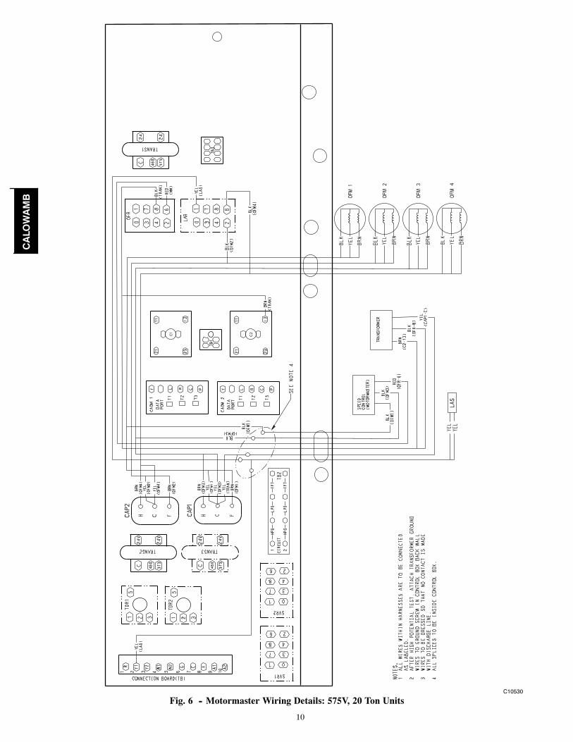
C10530
Fig. 6 -- Motormaster Wiring Details: 575V, 20 Ton Units
CALOWAMB

11
C10533
Fig. 7 -- Time Delay Relay (TDR) -- Location in Control Box for Single Coil Units
C10534
Fig. 8 -- Time Delay Relay (TDR) -- Location in Control Box for Dual Coil Units
Table 1 – Wind Baffle Dimension
DIMENSIONS --- INCHESUNIT BAFFLE A B C D E F G H J
15 TON
LEFT SIDE 19 3/4 20 1/2 21 1/4 43 1/8 8 3/8 18 27 1/4 40 ---BACK 80 1/4 81 81 3/4 43 1/8 8 3/8 18 27 1/4 40 ---
RIGHT SIDE 38 3/4 39 1/2 40 1/4 43 1/8 8 3/8 18 27 1/4 40 ---FRONT 34 1/8 34 7/8 35 5/8 43 1/8 6 7/8 16 1/2 25 3/4 38 1/2 ---
20 TON
LEFT SIDE 32 7/8 33 5/8 34 3/8 43 1/8 4 1/4 13 1/4 22 1/4 31 1/4 40 1/4BACK 47 3/4 48 1/2 49 1/4 43 1/8 4 1/4 13 1/4 22 1/4 31 1/4 40 1/4
RIGHT SIDE 61 1/8 61 7/8 62 5/8 43 1/8 3 3/4 12 3/4 21 3/4 30 3/4 39 3/4FRONT 20 1/8 20 7/8 21 5/8 43 1/8 3 3/4 12 3/4 21 3/4 30 3/4 39 3/4
DIMENSIONS --- MMUNIT BAFFLE A B C D E F G H J
15 TON
LEFT SIDE 501 520 539 1095 212 457 694 1015 ---BACK 2037 2056 2075 1095 212 457 694 1015 ---
RIGHT SIDE 983 1002 1021 1095 212 457 694 1015 ---FRONT 866 885 904 1095 174 419 656 977 ---
20 TON
LEFT SIDE 834 853 872 1095 108 337 565 794 1022BACK 1214 1233 1252 1095 108 337 565 794 1022
RIGHT SIDE 1551 1570 1589 1095 95 324 552 781 1010FRONT 510 530 549 1095 95 324 552 781 1010
CALOWAMB

12
C10363
Fig. 9 -- Wind Baffles -- Fabrication
CALOWAMB
13
C10366
Fig. 10 -- 15 Ton Wind Baffle Brackets -- Fabrication
CALOWAMB
14
RIG
HT
BA
CK
LEFT
FRO
NT
BO
TTO
MB
RA
CK
ET
TOP
BR
AC
KE
TS
OFM3
MM
OFM2
OFM1
MM
C13502
Fig. 11 -- Wind Baffle Installation — 15 Ton Units
CALOWAMB

15
RIG
HT
BA
CK
LEFT
FRO
NT
OFM
3M
M
OFM
4
OFM
2
OFM
1M
M
C13503
Fig. 12 -- Wind Baffle Installation — 20 Ton Units
CALOWAMB
16
38AUD/AUZ OPERATINGSEQUENCE
Fan on/off control in cooling--only units is provided by anoutdoor fan relay (OFR).In cooling mode, fan motor speed of outdoor motorsOFM1 and OFM3 is regulated by the speed controltemperature sensor on outdoor coil 1 for a minimum coilcondensing temperature of approximately 100_F (38_C)at higher outdoor ambient temperature and 80_F (27_C) atlower ambient. Additionally, outdoor fan motor OFM2and OFM4 are turned on/off by the low ambienttemperature switch, LAS, operating the low ambient relay(LAR). The LAS control temperatures are open 42_F +/--5_F, close 57_F +/-- 5_F (open 5.5_C +/-- 2.8_C, close13.9_C +/-- 2.8_C).To override the speed control for full fan speed operationduring service or maintenance, either:
a. Remove sensor and place in hot water >120_F(>49_C), or
b. Rewire to bypass control by connecting speedcontrol input and output power wires.
TROUBLESHOOTINGOBSERVATION POSSIBLE REMEDYFans won’t start All fans:
Check power & wiringCheck outdoor fan relay (OFR)OFM1, OFM3 only:Check speed control sensor locationCheck speed sensor resistanceOFM2, OFM4 only:Check low ambient switch (LAS)Check low ambient relay (LAR)
Cooling --- Center outdoorfans (OFM2, OFM4) offbelow approximately 60_F(16_C) outdoor ambient.
Normal operation
Cooling --- Center outdoorfans (OFM2, OFM4) noton above approximately60_F (16_C) outdoorambient
Check low ambient switch (LAS)Check low ambient relay (LAR)
Cooling --- Slow fan speedfor outer fans (OFM1,OFM3) at start or duringlow outdoor ambient
Normal operation
Cooling --- Slow fan speedfor outer fans (OFM1,OFM3) above 85_F (29_F)outdoor ambient (shouldbe full speed)
Check speed control sensor loca-tionCheck speed control sensorresistanceCheck fan motor capacitor
Cooling --- motor currentinto speed control isgreater than motor name-plate FLA
Normal operationUp to 30% higher A at partial speedat low ambient
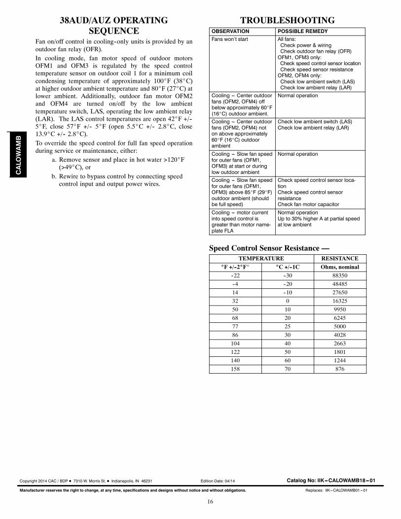
Speed Control Sensor Resistance —TEMPERATURE RESISTANCE
_F +/--2_F_ _C +/--1C Ohms, nominal
--22 --30 88350
--4 --20 48485
14 --10 27650
32 0 16325
50 10 9950
68 20 6245
77 25 5000
86 30 4028
104 40 2663
122 50 1801
140 60 1244
158 70 876
Copyright 2014 CAC / BDP D 7310 W. Morris St. D Indianapolis, IN 46231 Edition Date: 04/14
Manufacturer reserves the right to change, at any time, specifications and designs without notice and without obligations.
Catalog No: IIK---CALOWAMB18---01
Replaces: IIK---CALOWAMB01---01
CALOWAMB