installation instructions -...
TRANSCRIPT

TP-PRH-A, TP-NRH-APerformance™ SeriesEdge� Thermidistat� Control
Installation Instructions
A07049 A07048
Programmable Control Non−Programmable Control
Designed and Assembledin the USA.
NOTE: Read the entire instruction manual before starting the installation.US patents: US7287709 B2, US20080147242 A1, USD582800 SI, US20060165149 A1, US6956463 B2.

2
TABLE OF CONTENTSPAGE
SAFETY CONSIDERATIONS 2. . . . . . . . . . . . . . . . . . . . . . . . . . . . . . . . . . . . INTRODUCTION 3. . . . . . . . . . . . . . . . . . . . . . . . . . . . . . . . . . . . . . . . . . . . . . INSTALLATION CONSIDERATIONS 4. . . . . . . . . . . . . . . . . . . . . . . . . . . . . .
INSTALLATION 8. . . . . . . . . . . . . . . . . . . . . . . . . . . . . . . . . . . . . . . . . . . . . . . SYSTEM START−UP AND CHECKOUT 45. . . . . . . . . . . . . . . . . . . . . . . . . .
OPERATIONAL INFORMATION 55. . . . . . . . . . . . . . . . . . . . . . . . . . . . . . . . TROUBLESHOOTING 60. . . . . . . . . . . . . . . . . . . . . . . . . . . . . . . . . . . . . . . . .
WIRING DIAGRAMS 64. . . . . . . . . . . . . . . . . . . . . . . . . . . . . . . . . . . . . . . . . . THERMIDISTAT CONTROL CONFIGURATION RECORD 84. . . . . . . . . . .
SAFETY CONSIDERATIONSRead and follow manufacturer instructions carefully. Follow all local electricalcodes during installation. All wiring must conform to local and national electricalcodes. Improper wiring or installation may damage Thermidistat Control.
Recognize safety information. This is the safety−alert symbol . When you seethis symbol on the equipment and in the instruction manual, be alert to thepotential for personal injury.
Understand the signal words DANGER, WARNING, and CAUTION. Thesewords are used with the safety−alert symbol. DANGER identifies the mostserious hazards which will result in severe personal injury or death. WARNINGsignifies a hazard which could result in personal injury or death. CAUTION isused to identify unsafe practices which may result in minor personal injury orproduct and property damage. NOTE is used to highlight suggestions which willresult in enhanced installation, reliability, or operation.

3
INTRODUCTIONCarrier’s 7−day, 5/2−day, 1−day programmable and non−programmablePerformance Series Thermidistat Control is a wall−mounted, low−voltagecontrol which combines temperature and humidity control in either a single unitor a two−piece unit. In two−piece configuration, the relays are located near theequipment and a two−wire connection is used between the Display Module andthe Equipment Control Module. Single−piece installation requires more wiringand results in a higher profile. The Edge� Thermidistat has no need for batteriesto store user−configured settings in memory. During power loss its internalmemory saves settings for unlimited time, and the clock continues to run for atleast 24 hours. An extension of Carrier’s proven line of thermostats; it providesseparate setpoints for heating and cooling in addition to humidification anddehumidification.In the Edge Thermidistat Control programmable configuration, different heatingand cooling setpoints and times are programmable for 4 periods per day or 2periods per day. Programming can be done for 7 days per week, 5/2 days perweek, or 1 day. The programmable Thermidistat Control can also be userconfigured as a non−programmable Thermidistat Control. When operating asnon−programmable, the Edge Thermidistat Control will still have bothtemperature and humidity control.The non−programmable Thermidistat Control features Touch ’N’ Go� settingsfor quick and easy temperature change without complicated programmingschedules. The non−programmable Edge Thermidistat Control will still haveboth temperature and humidity control. And, its Touch ’N’ Go technologyenables the user to switch between three different user−configurable settingsthrough intuitive buttons located just below the display.
4
INSTALLATION CONSIDERATIONSPowerThis control is powered by 24VAC only. It requires 24VAC (Rh and/or Rc and Cterminals) of the low−voltage transformer to be connected to it for properoperation. It will not operate without these 2 connections. Rh and Rc areconnected via PCB breakout jumper. See Fig. 1. For applications using two24VAC transformers, one in the indoor unit and one in the outdoor unit, connectthe common from each to the C terminal. Connect R from the indoor unit to theRh terminal. Connect R from the outdoor unit to the Rc terminal. Then, breakjumper on the circuit board. The W and HUM signals are taken from the Rhpower and the G signal is taken from the Rc power. If Thermidistat Control hasbeen installed in a two−transformer application that is later changed to asingle−transformer installation, installer must install a field supplied jumperbetween Rc and Rh. Depending on the installation, up to 14 wires may berequired. Installation as two−piece unit is recommended. Only 2 wires arerequired for connection between Display Module and Equipment ControlModule. These two wires (V+ and Vg) do not provide ordinary 24VAC. Theycarry a combination of power and communications data that is unique to theseproducts.

5
A07052
Fig. 1 − PCB Breakout Jumper
ModelsThere are programmable and non−programmable models for all applications.They can be configured for AC or HP, 1−or 2−speed compressor, and for HybridHeat� installations, allowing it to be used in place of all Carrier thermostats.Programmable Thermidistat Controls may be configured as non−programmableif user desires.
Humidify Equipment and ConnectionsThe humidify output connects directly to 24VAC operated humidifiers. Anisolation relay may be required when using powered humidifiers. No otherconnection or interlock is required. Any of several installer−selectable operatingmodes are available.
6
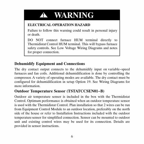
ELECTRICAL OPERATION HAZARD
Failure to follow this warning could result in personal injuryor death.
DO NOT connect furnace HUM terminal directly toThermidistat Control HUM terminal. This will bypass furnacesafety controls. See Low Voltage Wiring Diagrams and notesfor proper connection.
! WARNING
Dehumidify Equipment and ConnectionsThe dry contact output connects to the dehumidify input on variable−speedfurnaces and fan coils. Additional dehumidification is done by controlling thecompressor. A variety of operating modes are available. The dry contact must beconfigured for dehumidification in setup Option 19. See Wiring Diagrams formore information.
Outdoor Temperature Sensor (TSTATCCSEN01−B)Outdoor air temperature sensor is included in the box with the ThermidistatControl. Optimum performance is obtained when an outdoor temperature sensoris used with the Thermidistat Control. Plan installation so that 2 wires can be runfrom Equipment Control Module to an outdoor location, preferably on the northside of the house or refer to Installation Instructions included with the outdoortemperature sensor for simplified connection. Sensor can be mounted to outdoorunit and existing control wires may be used for its connection. Details areprovided in sensor instructions.

7
Remote Indoor Temperature SensorA remote temperature sensor may be used with the programmable model, whereit is desirable to install the Thermidistat Control in a limited access location whilemeasuring the temperature in the living space. The remote room sensor may beused as a stand alone or average with local sensor.
Two−Piece Thermidistat Control ConfigurationThe Performance Series Thermidistat Control can be installed in one of twoconfigurations. The control may be installed as a single−piece ThermidistatControl or it may be split into two pieces and mounted in separate locations. Asa single−piece unit, all required wiring must be brought to the EquipmentControl Module for connection to the terminal strip. In two−piece configuration,the Display Module can be mounted in the living space while the EquipmentControl Module may be mounted near the indoor furnace or fan coil. Connectionfrom the Display Module to the Equipment Control Module requires only twowires. All other control wires are connected to the Equipment Control Modulefrom the HVAC equipment. This configuration results in a slimmer display andlocates the Equipment Control Module containing the switching relays awayfrom the main living space where relay clicking will not be heard.The model numbers on the Display Module and the Equipment Control Module(ECM) must match or unpredictable results may occur.Two−wire pigtail replacement part number is TX−2WR05.
WiringWire length should be no more than 250 ft (76 m). Use 22 AWG or larger fornormal wiring applications. Continuous wire lengths over 100 ft (30.5 m) shoulduse 20 AWG or larger.
8
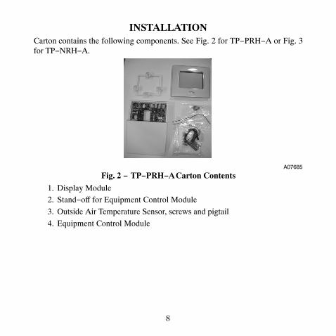
INSTALLATIONCarton contains the following components. See Fig. 2 for TP−PRH−A or Fig. 3for TP−NRH−A.
A07685
Fig. 2 − TP−PRH−A Carton Contents
1. Display Module2. Stand−off for Equipment Control Module
3. Outside Air Temperature Sensor, screws and pigtail
4. Equipment Control Module

9
A07686
Fig. 3 − TP−NRH−A Carton Contents
1. Display Module
2. Stand−off for Equipment Control Module3. Outside Air Temperature Sensor, screws and pigtail
4. Equipment Control Module
Thermidistat Control LocationThermidistat Control should be mounted:
� Approximately 5 ft (1.5m) from floor.� Close to or in a frequently used room, preferably on an inside
partitioning wall.� On a section of wall without pipes or duct work.
Thermidistat Control should NOT be mounted:� Close to a window, on an outside wall, or next to a door leading to the
outside.

10
� Exposed to direct light or heat from a lamp, sun, fireplace, or othertemperature−radiating objects which could cause a false reading.
� Close to or in direct airflow from supply registers and return−airregisters.
� In areas with poor air circulation, such as behind a door or in analcove.
Installer should determine whether control will be installed as single−piece ortwo−piece. In single−piece configuration, as many as 14 wires may need to runto wall mounting location for connection to the control. In two−piececonfiguration, the Display Module and Equipment Control Module areconnected by two wires.
Install Thermidistat Control
ELECTRICAL OPERATION HAZARD
Failure to follow this warning could result in personal injuryor death.
Before installing Thermidistat Control, turn off all power toequipment. There may be more than 1 power disconnect.
! WARNING

11
UNIT DAMAGE HAZARD
Failure to follow this caution may result in equipment damageor improper operation.
Improper wiring or installation may damage ThermidistatControl. Check to make sure wiring is correct beforeproceeding with installation or turning on power.
CAUTION!
1. Turn off all power to equipment.
2. If an existing Thermidistat Control or thermostat is being replaced:a. Remove existing control from wall.
b. Disconnect wires from existing thermostat, 1 at a time.c. As each wire is disconnected, record wire color and terminal marking.
d. New or additional wires may be needed to accommodate addedhumidity outputs.
e. Discard or recycle old control.

12
ENVIRONMENTAL HAZARD
Failure to follow this caution may result in environmentaldamage.
Mercury is a hazardous waste. Federal regulations require thatMercury be disposed of properly.
CAUTION!
Two−Piece InstallationThe following steps should be followed for the installation of the two−piececonfiguration.NOTE: The 2−wire pigtail is not intended to support the weight of the DisplayModule. Do not hang the Display Module from the Equipment Control Modulescrew terminals.
1. Remove mounting plate from back of Display Module by pressing thetwo tabs on the bottom edge and pulling away. See Fig. 4 and 5.

13
A07225
Fig. 4 − Press Tabs to Remove Backplate
A07226
Fig. 5 − Take Apart

14
2. Route wires through large hole in mounting base. Level mounting baseagainst wall (for aesthetic value only—Display Module need not beleveled for proper operation) and mark wall through 4 mounting holes.To avoid unintended bending of wall plate plastic, use all 4 screws andanchors. See Fig. 6.
A07165
Fig. 6 − Backplate Mounting
3. Drill four 3/16−in. mounting holes in wall where marked. ThermidistatControl may be mounted to a standard junction box, if desired. Holepattern on Thermidistat Control mounting base matches junction boxmounting holes.
4. Secure rear plastic mounting base to wall with 4 screws and anchorsprovided. To avoid unintended bending of wall plate plastic, use all 4screws and anchors. Make sure all wires extend through hole in mountingbase.
5. Adjust length and routing of each wire to reach proper connector blockand terminal on mounting base with 1/4−in. (6 mm) extra wire.
15
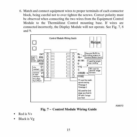
6. Match and connect equipment wires to proper terminals of each connectorblock, being careful not to over tighten the screws. Correct polarity mustbe observed when connecting the two wires from the Equipment ControlModule to the Thermidistat Control mounting base. If wires areconnected incorrectly, the Display Module will not operate. See Fig. 7, 8and 9.
A08072
Fig. 7 − Control Module Wiring Guide� Red is V+
� Black is Vg

16
A07166
Fig. 8 − Secure Wires to Terminal Strip
A07167
Fig. 9 − Connect Pigtail Wires to Display Module
17
NOTE: The 2−wire pigtail is not intended to support the weight of the DisplayModule. Do not hang the Display Module from the Equipment Control Modulescrew terminals.� Red of the pigtail is V+
� Black of the pigtail is Vg
7. Push any excess wire into wall and against mounting base. Seal hole inwall to prevent air leaks. Leaks can affect operation and cause incorrecttemperature and/or humidity measurement.
8. Make sure to attach 2−wire pigtail to Display Module mounting base. It ispacked loose in the box from the factory. Then attach 2−wire pigtail to theback of the Display Module via 2 pin, keyed connector.
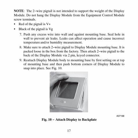
9. Reattach Display Module body to mounting base by first setting on at topof mounting base and then push bottom corners of Display Module tosnap into place. See Fig. 10.
A07168
Fig. 10 − Attach Display to Backplate

18
10. Find suitable indoor mounting location for Equipment Control Module,either near or on equipment. See Fig. 11.
IMPORTANT NOTE: Equipment Control Module should not be mountedto duct work or below any other controls or equipment (i.e. humidistat,humidifier, etc.).
A07217
Fig. 11 − Equipment Control Module on Equipment11. Route wires through rear of Equipment Control Module using either a
clearance hole or supplied standoff. See Fig. 12.

19
A07227
Fig. 12 − Standoff
NOTE: Standoffs are provided as an aid when installing Equipment ControlModule on inside equipment or a solid wall.
12. Match and connect equipment wires to proper terminals of each connectorblock being careful not to over tighten the screws. Correct polarity mustbe observed when connecting the two wires from the Equipment ControlModule to the Thermidistat Control mounting base. If wires areconnected incorrectly, the Display Module will not operate. See Fig. 7, 8and 9.
13. Snap cover over top of Equipment Control Module. See Fig. 13.

20
A07218
Fig. 13 − Cover on Equipment Control Module
14. Turn on power to equipment. On power up, all display segments willlight for 5 sec. For the next 5 sec a 2−digit code appears on large displaywhich identifies Thermidistat Control configuration. Refer to Option 33.
a. AC — 1−stage air conditioner with furnace or fan coilb. HP — 1−stage heat pump with fan coil
c. A2 — 2−stage air conditioner with furnace or fan coil
d. H2 — 2−stage heat pump with fan coile. hh — Hybrid Heat system with 1−stage heat pump
f. h2 — Hybrid Heat system with 2−stage heat pumpg. H — heating only system
h. C — cooling only system
21
Single−Piece InstallationThe following steps should be followed for the installation of the single−piececonfiguration.
1. Remove cover from Equipment Control Module by pressing the two tabson the bottom edge and pulling away. Route wires through large hole inEquipment Control Module. Level Equipment Control Module againstwall (for aesthetic value only − Equipment Control Module need not beleveled for proper operation) and mark wall through 4 mounting holes.
2. Drill two 3/16−in. mounting holes in wall where marked. ThermidistatControl may be mounted to a standard junction box if desired. Holepattern on Equipment Control Module matches junction box mountingholes.
3. Secure rear plastic Equipment Control Module to wall with 4 screws andanchors provided. To avoid unintended bending of wall plate plastic, useall 4 screws and anchors. Make sure all wires extend through hole inEquipment Control Module.
4. Adjust length and routing of each wire to reach proper connector blockand terminal on Equipment Control Module with 1/4−in. (6 mm) extralength. See Fig. 14.

22
A07219
Fig. 14 − Equipment Control Module
5. Match and connect equipment wires to proper terminals of each connectorblock.
6. Push any excess wire into wall and against Equipment Control Module.Seal hole in wall to prevent air leaks. Leaks can affect operation and causeincorrect temperature and/or humidity measurement.
7. Attach 2−wire pigtail to Equipment Control Module terminal block(terminals V+ and Vg). Attach 2−wire pigtail to the back of the DisplayModule via 2 pin, keyed connector.
8. Reattach Display Module body to Equipment Control Module by firstsetting on at top and then push bottom corners to snap into place. See Fig.15.

23
A07220
Fig. 15 − Reattach Display Module
9. Turn on power to equipment. On power up, all display segments willlight for 5 sec. For the next 5 sec a 2−digit code appears on large displaywhich identifies Thermidistat Control configuration. Refer to Option 33.
a. AC — 1−stage air conditioner with furnace or fan coilb. HP — 1−stage heat pump with fan coil
c. A2 — 2−stage air conditioner with furnace or fan coil
d. H2 — 2−stage heat pump with fan coile. hh — Hybrid Heat system with 1−stage heat pump
f. h2 — Hybrid Heat system with 2−stage heat pumpg. H — heating only system
h. C — cooling only system

24
Set Thermidistat Control ConfigurationConfiguration options enable the installer to configure the Thermidistat Controlfor a particular installation. Most are not presented to the homeowner andtherefore must be properly set by the installer. (Only those marked with anasterisk * below are available to the homeowner.) The homeownerconfigurations are described in the owner’s manual. A special procedure allowsentry into the configuration mode. Selections can be made while in configurationmode. Description of each selection and how to use the configuration modefollows.CONFIGURATION OPTIONS − SUMMARY
Option 01 — Equipment TypeOption 02 — Clean Filter Timer Adjustment
Option 03* — Fahrenheit/Centigrade SelectionOption 04 — Fan (G) on with W/W1 SelectionOption 05 — Room Air Temperature Sensing (programmable
models only)Option 06 — Cooling Lockout Below 55�F/13�C Selection (only
available if outdoor air sensor is present)Option 07 — Zoning
Option 08 — Auxiliary Heat Lockout Temperature Setting (only available when heat pump is used and when outdoor air temperature sensor is present)
Option 09 — Heat Pump Lockout Temperature Balance Point (only available when outdoor air temperature sensor is present)
Option 10 — Reversing Valve
25
Option 11 — Adjustable Setpoint Deadband (not available on heat only and cool only systems)
Option 12 — Smart Recovery (programmable models only)
Option 13 — Room Temperature Offset AdjustmentOption 14 — Humidity Offset AdjustmentOption 15 — Enable Auto Mode
Option 16 — Cycles Per HourOption 17 — Time Between Stages
Option 18* — Backlight ConfigurationOption 19 — Dry ContactOption 20 — Outdoor Air Temperature Offset Adjustment
Option 21* — Keypad LockoutOption 22 — High Cool Latch Temperature
Option 23 — High Heat Latch TemperatureOption 24* — Programmable/Non−Programmable
(programmable models only)
Option 25* — Number of Programmable Periods per Day (programmable models only)
Option 26 — Minimum Cooling SetpointOption 27 — Maximum heating Setpoint
Option 28 — UV Light ReminderOption 29 — Humidifier Pad ReminderOption 30* — Programmable Fan (programmable models only)

26
Option 31* — Daylight Savings Time Configuration (programmable models only)
Option 32 — Furnace Heat Staging
Option 33 — Single or Two−Piece InstallationOption 34 — Hybrid Heat Furnace LatchOption 40 — Fan Humidify
Option 41 — Variable Speed BlowerOption 42 — Variable Speed Super Dehumidification
Option 43 — Intelligent Heat StagingOption 44 — Super Comfort HeatOption 99 — Reset to Factory Defaults
TO ENTER CONFIGURATION MODEPress and hold FAN button for approximately 10 sec. The Display Module isnow in configuration mode. It will automatically exit this mode if no button ispressed for 3 minutes. Pressing the DONE button will exit configuration modeimmediately.
WHILE IN CONFIGURATION MODEThe option number is displayed in the heat setpoint location and theconfiguration setting is displayed in the cool setpoint location. On theTP−PRH−A (programmable) model, a box will surround the option number. Themode button is used to move the box between the two displayed values. The softkeys below the listed values may also be used to move the box between selectedvalues. The value inside the box is changed by using the UP/DOWN buttons. Onthe TP−NRH−A (non−programmable) model, one of the values will be flashing.The mode button is used to change which value is flashing or the Home andSleep buttons may also be used to select which value to flash. The value that is

27
flashing is changed by using the UP/DOWN buttons. All changes made aresaved at the time of selection and will be saved in the event of the 3 minutetime−out or when installer exits from configuration menu.
Configuration Options —SelectionOption 01 — Equipment TypeRange: H2, A2, HP, AC, hh, h2, H, CH2 — operates a two−speed heat pump with a fan coilHP — operates a single−speed heat pump with a fan coil
A2 — operates a two−speed AC with a fan coil or furnaceAC — operates a single−speed AC with a fan coil or furnace
hh — operates a single−speed heat pump with a furnaceh2 — operates a two−speed heat pump with a furnaceH — operates a heat−only system. Furnace or fan coil only;
no outdoor unit.C — operates a cool only−system. Outdoor AC unit with an
indoor fan coil with no strip heaters.Default is H2.Option 02 — Clean Filter TimerSelect hours of blower operation (heating, cooling, or fan) before CHECKFILTER icon is displayed. With OF selected, icon will never come on, disablingthis feature. Time selection can range from 800 to 7200 hr by selecting numbers1 through 9. (Time is 800 X number selected.) Default is 4 (3200 hr).
Recommended selections are disposable filter−800 to 2400 hr, media filter−2400to 3200 hr, or electronic air cleaner−1600 to 2400 hr of blower operation. Forhigher efficiency filter, please consult filter’s Installation Instruction for details.

28
Option 03 — Fahrenheit/CentigradeSelect between Fahrenheit (F) and Centigrade (C) operation. Factory default isFahrenheit (F).Option 04 — Fan (G) On With W/W1This selection determines whether fan (G) output is to be On or OFF when anyW/W1 (furnace or strip heat) output is On. Most furnaces and fan coils managetheir own blowers and do not require separate G signal. For these applications,select OFF. Some auxiliary heaters require separate G signal to turn on blower. Inthis case, select On.
Default is OF (off).Option 05 — Room Air Temperature Sensing (programmable models only)
The remote room sensor may be installed as a single sensor or multiple sensorsmay be installed for further averaging functionality. See Fig. 16
Sensor 1 Sensor 2
Sensor 3 Sensor 4
RRS SRTN
A09130
Fig. 16 − Remote Room Sensor − Parallel Wiring

29
This selection determines which sensor the control will use for measuring roomair temperature. Room air temperature can be sensed in one of three ways; thelocal sensor (L) located on the Display Module, the remote room air sensor (r),or the average of local and remote sensors (Lr). Settings are L, r, Lr.Default is L.Option 06 — Cooling Lockout Below 55�F/13�C
This selection disables cooling when outdoor temperature is below 55�F/13�C.It requires an outdoor temperature sensor. Setting is not available if valid outdoorsensor is not connected. Set to OF (off) to allow cooling below 55�F/13�C. Setto On to prevent cooling below 55�F/13�C.Factory default is OF (off).Option 07 — ZoningThis selection should be set to On when the Thermidistat Control is to be used aspart of a zoning system. It is assumed that the zoning equipment will take care oftime guard and cycle timers. The minimum On time is still controlled by theThermidistat Control.Default is OF (off).Option 08 — Auxiliary Heat Lockout TemperatureThis selection is available on heat pump systems with a valid outdoortemperature sensor connected. Available settings are: Off, 5, 10, 15, 20, 25, 30,35, 40, 45, 50, 55.OF (off) − function is disabled. Auxiliary heat is allowed to operate wheneversufficient demand for heat is available.
5 to 55�F (−15 to 13�C) − Outdoor temperature above which the auxiliary heatis not allowed to operate (unless MODE is set to Emergency Heat). If room
30
temperature falls below 45�F (7�C), the auxiliary heat will be allowed to turn onand will continue to run until demand is satisfied.Default is OF (off).Option 09 — Heat Pump Lockout Temperature Balance Point (onlyavailable when heat pump is used and when outdoor air temperature sensoris present)This selection is only available on Hybrid Heat systems. A Hybrid Heat systemis selected via the Option 1 Equipment Type configuration. Configurationssettings are: OF (off), 5, 10, 15, 20, 25, 30, 35, 40, 45, 50, 55.
OF (off) — the heating cycle will always start with heat pump heating.5 to 55�F (−15 to 13�C) — the outdoor temperature below which heat pumpoperation is not allowed.
When emergency heat mode is selected, only auxiliary heat will operate.Default is OF (off).Option 10 — Reversing ValveThis selection is only available on heat pump systems. “O” terminal can beconfigured to be energized in either heating mode or in cooling mode, dependingon heat pump operation. “O” is used to describe a heat pump system thatenergizes its reversing valve in cooling. “B” is used to describe a heat pumpsystem that energized its reversing valve in heating.H — Reversing valve output (O/W2/B) is energized when HEAT mode isselected.C — Reversing valve output (O/W2/B) is energized when COOL mode isselected.
Default is C.

31
Option 11 — Deadband Setting Between Heat & CoolThis option is not available on Heat Only and Cool Only systems. The selectionallows the installer to choose how much differential exists between the heatingand cooling setpoints. Allowable selections are 1 thru 6.
Default is 2.Option 12 — Smart Recovery
Smart Recovery OF (off) means setpoints change precisely at setback recoverytime. Thirty, 60, or 90 selects the number of minutes recovery starts beforeprogrammed recovery time. Recovery takes place smoothly during the selectedrecovery time, ending at the recovery time and temperature which isprogrammed. Not available with non−programmable Thermidistat Controls orwhen Thermidistat Control is configured as non−programmable.Default is 90.
Option 13 — Room Air Temperature Offset AdjustThe number of degrees to be added to the displayed temperature to calibrate ordeliberately miscalibrate the measured room temperature ( −5 to +5�).Default is 0.Option 14 — Humidity Display Offset Adjust
The percentage to be added to the displayed humidity to calibrate or deliberatelymiscalibrate the measured room humidity (−9% to +9% RH).Default is 0.Option 15 — Enable Auto Mode
This selection is not available if the Thermidistat Control is configured as HeatOnly or Cool Only in Option 1. This allows the homeowner to select autochangeover mode in addition to heat and cool. This allows the Thermidistat
32
Control to automatically change between heating mode and cooling mode whensufficient demand for heating or cooling exists.On — Auto mode is available.
OF — Auto mode is not available.Default is On.Option 16 — Maximum Cycles Per Hour
This selection limits the number of cycles per hour that the Thermidistat Controlallows the system to operate. Selections are 2, 4, 6.
2 — The heating and cooling outputs will be energized no more than 2 times perhour. When an output is energized, it will not be energized again for 30 minutes.
4 — The heating and cooling outputs will be energized no more than 4 times perhour. When an output is energized, it will not be energized again for 15 minutes.6 — The heating and cooling outputs will be energized no more than 6 times perhour. When an output is energized, it will not be energized again for 10 minutes.Default is 4.
Option 17 — Time Between Equipment StagesThis selection is only available for heat pump systems. This determines theminimum number of minutes of equipment operation on the highest compressorstage before allowing the transition to auxiliary heat. Available selections are 10,15, 20, and 25. The time between stages of any individual piece of equipment,such as low speed and high speed compressor or fan coil stages, will be fixed at10 minutes.
Default is 15.

33
Option 18 — Backlight Configuration
When OF (off), the backlight will be lit for 10 seconds after a button is pressed.After 10 seconds of no button presses, the backlight turns off. When On, thebacklight will normally be on and dim in appearance. The backlight brightnessbecomes brighter when a button is pressed. After 10 seconds of no buttonpresses, the backlight will return to the dimmer level until another button pressoccurs. The range of brightness is 1 through 5 with 5 being full brightness.Default is 3.
Option 19 — Dry Contact Configuration (programmable models only)There are 3 available selections, OF, 1 and 2.
OF — The dry contact is always de−energized.1 — The dry contact will be energized for the specified number of minutes perhour. This selection is programmable by period. When this selection is changedfrom OF to 1, the period icons are shown and the minute segments of the clockdisplay are shown. The triangle icon next to the WAKE period will be on and avalue between 0 and 60 will be shown in the minutes display. See OperationalInformation and Wiring Diagrams for further explanation of dry contactconfiguration and use. To change the period or minutes, press the soft key belowthe period or minutes and then use the UP/DOWN buttons to change to thedesired value.2 — The dry contact will operate as a DH relay. This relay is reverse logic. Whenthe humidity level is above the dehumidify setpoint, the dry contact D1−D2 willbe opened. When the humidity level is below the dehumidify setpoint, D1−D2will be closed. There is a +/− 2% hysteresis around the dehumidify setpoint toprevent rapid on/off cycling of the DH output. When configured fordehumidification, the Rc terminal must be connected to one of the dry contactterminals. This provides power to energize the dehumidify terminal on the
34
cooling equipment when the dry contact is closed. See Wiring Diagrams formore information.Default is OF (off).
Option 19 — Dry Contact Configuration (non−programmable models only)OF — The dry contact is always de−energized.
ON — The dry contact will operate as a DH relay. This relay is reverse logic.When the humidity level is above the dehumidify setpoint, the dry contactD1−D2 will be opened. When the humidity level is below the dehumidifysetpoint, D1−D2 will be closed. There is a +/− 2% hysteresis around thedehumidify setpoint to prevent rapid on/off cycling of the DH output. Whenconfigured for dehumidification, the Rc terminal must be connected to one of thedry contact terminals. This provides power to energize the dehumidify terminalon the cooling equipment when the dry contact is closed. See Wiring Diagramsfor more information.Default is OF (off).
Option 20 — Outdoor Air Temperature Offset AdjustmentThis selection allows the calibration, or deliberate miscalibration of the outdoorair temperature sensor reading. The selection ranges from −5 to +5�.Default is 0.
Option 21 — Keypad Lockout (programmable models only)This selection allows the installer to limit access to the keypad. Selections are OF(off), 1, 2, 3. These options are independent of Option 24, which allows theprogrammable model to be configured as a non−programmable thermostat.
OF (off) — The user has full access to the keypad.1 — The user has access to change the setpoints, time of day and calendar.

35
2 — The user has access to change the setpoints only.
3 — The entire keypad is locked. When a button is pressed, the backlight willturn on but none of the operating parameters will be changed.
When the keypad lock selection is turned on, the padlock icon will be displayed.To unlock the keypad, press and hold the UP/DOWN buttons simultaneously forfive seconds. When the keypad is unlocked, the padlock icon will turn off. Thekeypad will remain unlocked for two minutes after the last button press. Aftertwo minutes with no button presses, the keypad will lock again. The keypad willnot lock in the software configuration mode or in the installer test mode.Default is OF (off).Option 21 — Keypad Lockout (non−programmable models only)
This selection allows the installer to limit access to the keypad. Selections are OF(off), 1, 2.
OF (off) — The user has full access to the keypad.1 — The user has access to modify Home, Sleep, Away, and UP/DOWNsetpoints.2 — The entire keypad is locked. When a button is pressed, the backlight willturn on but none of the operating parameters will be changed.When the keypad lock selection is turned on, the padlock icon will be displayed.To unlock the keypad, press and hold the UP/DOWN buttons simultaneously forfive seconds. When the keypad is unlocked, the padlock icon will turn off. Thekeypad will remain unlocked for two minutes after the last button press. Aftertwo minutes with no button presses, the keypad will lock again. The keypad willnot lock in the software configuration mode or in the installer test mode.Default is OF (off).

36
Option 22 — High Cool Latch Temperature (only available if outdoorsensor is present)
An outdoor sensor is required for high cool latch feature.This selection is only available when Option 1 is set to H2, A2, or h2 and whenOption 7 (zoning) is set to OF (off). Configuration settings are OF (off), 80, 85,90, 95, 100, 105, 110, On.OF (off) — Cooling always starts in low stage (Y1) and stages up to high stage(Y1 and Y/Y2) when demand is sufficient and staging timer constraints havebeen satisfied.80 to 110�F (27 to 43�C) — Outdoor temperature above which both first andsecond stages of the compressor are energized to satisfy all cooling demands.When a cycle starts under a high cool latch, it will finish the cooling cycle onhigh stage. If the cooling equipment is energized to satisfy a dehumidify demandonly (no cooling demand), the latch will not be applied.
On — The Y1 and Y/Y2 outputs are simultaneously energized to satisfy allcooling demands.Default is OF (off).
Option 23 — High Heat Latch Temperature (only available if outdoorsensor is present)
This selection is only available when Option 1 is set to H2, or h2 and Option 7(zoning) is set to OF (off). Configuration settings are OF (off), 20, 25, 30, 35, 40,45, 50, On.OF (off) —Heating always starts in low stage (Y1) and stages up to high stage(Y1 and Y/Y2) when demand is sufficient and staging timer constraints havebeen satisfied.
37
20 to 50�F (−7 to 10�C) — Outdoor temperature below which both first andsecond stages of the compressor are energized to satisfy all heating demands.When a cycle starts under a high heat latch, it will finish the heating cycle onhigh stage.On — The Y1 and Y/Y2 outputs are simultaneously energized to satisfy allheating demands.
Default is OF (off).Option 24 — Programmable/Non−Programmable (programmable modelsonly)This selection allows the installer to configure the Thermidistat Control as eitherprogrammable or non−programmable. Selections are P, nP.Default is P.
Option 25 — Number of Programmable Periods (programmable modelsonly)
This selection allows the installer to configure the Thermidistat Control for twoor four periods per day. Two periods is a common commercial application andfour periods is more common for residential. This selection is not available ifOption 24 has been set to nP to configure the Thermidistat Control fornon−programmable operation.2 — Periods DAY and SLEEP are available
4 — Periods WAKE, DAY, EVE, and SLEEP are available.Default is 4.Option 26 — Minimum Cooling Setpoint
This selection allows the installer to configure the minimum cooling setpoint thatthe user is allowed to set. The range is based on the value of the adjustable

38
deadband Option 11, such that the minimum of the range is 50�F/10�C plus theadjustable deadband and the maximum is 90�F/32�C.Default is 52�F/11�C (based on the adjustable deadband default = 2).
Option 27 — Maximum Heating SetpointThis selection allows the installer to configure the maximum heating setpoint.The range is based on the adjustable deadband value Option 11, such that theminimum of the range is 50�F/10�C and the maximum is 90�F/32�C minus thedeadband.
Default is 88�F/31�C (based on the adjustable deadband default = 2).Option 28 — UV Light Reminder
This selection allows the installer to select the number of months after which theUV Light icon will be displayed to indicate to the homeowner that it is time tocall the dealer to have the UV Lights replaced. Selections available are OF (off),6, 12, 18, 24, 30, 36, 42, 48.
OF (off) — The UV Light reminder is turned off and will never be displayed.6−48 — The number of months after which the UV Light reminder will bedisplayed, “CHECK UV LIGHT”.
Default is OF (off).Option 29 — Humidifier Pad Reminder
This selects the number of months after which the Humidifier Pad Remindericon will be displayed. This is not based on run time.
OF (off) — The Humidifier Pad Reminder is disabled and will never bedisplayed.
39
1−24 — The number of months after which the Humidifier Pad Reminder iconwill be displayed, “CHECK HUM PAD”.Default is OF (off).
Option 30 — Programmable Fan (programmable models only)This selection allows the homeowner to program the fan selection to “Auto” or“On” fan operation for each of the program schedule periods. This selection isonly available on programmable Thermidistat Controls.OF (off) — Programmable fan is disabled and the homeowner must manuallyselect “Auto” or “On” for fan operation.On — Programmable fan is enabled. The homeowner can program “Auto” or“On” fan operation along with the heat and cool setpoints for each programmedperiod. When the program schedule is running, the programmed heat setpoint,cool setpoint, and fan selection for that period will be used. If the homeowner“overrides” the programmed fan setting by pressing the fan button, the overrideselection will remain in effect until the next programmed period time.
Default is OF (off).Option 31 — Daylight Savings Time Configuration (programmable modelsonly)This selection allows the installer to set the Thermidistat Control to automaticallychange by one hour on the specified day, month, and week specified.OF (off) — Daylight Savings Time Function disabled.
1,2 On — The first time the UP/DOWN button is pressed, the value of thisselection changes from OF (off) to 1. When 1 is displayed, the days of the weekand clock digits will be turned on. The installer will set the start date (Spring) forDaylight Savings Time by setting the day of the week by selecting theappropriate triangle icon next to the days of the week, the month of the year will
40
be set in the clock hours location (range 1−12) and the week of the month will beset in the clock minutes location. The week of the month selections will be F, 2,3, 4, and L for First, 2nd, 3rd, 4th, and Last. So for the first Sunday in April, thedisplay would show SUN, 4, F. When 2 is displayed, the installer will thenchoose the end date for daylight savings time (Fall). To activate the function, theinstaller changes the “2” by pressing the up button and “On” is displayed. Thesetting shall be left “On” to enable the Daylight Savings Time function.Default is On (on).
Option 32 — Furnace Heat Staging Control (available only when theThermidistat Control is configured to operate AC or A2 equipment).
1 — Thermidistat Control controls W1 output only and furnace controls the turnon and turn off of higher stages of heat.
2 — Thermidistat Control will control the W1 and O/W2/B outputs.Default is 1.
Option 33 — Single or Two−Piece InstallationThis configuration allows the Thermidistat Control to compensate for theamount of heat generated by the Thermidistat Control electronics to allow moreaccurate sensing of the temperature sensor. The amount of heat compensationwill be different between single installation and two−piece installation.
Range: 1P or 2P1P — The installation is single piece.
2P — The installation is two separate pieces.Default is 2P.
41
Option 34 − Hybrid Heat Furnace Latch
This selection allows a Hybrid Heat system to finish a heating cycle using thefurnace.
On − Once the furnace is on, it will finish the heating cycle with the furnace. If aheat pump defrost occurs, the heating cycle will finish with the furnace.
OF − The system will stage from furnace back to heat pump if heating demanddictates, or 2 minutes after a defrost has ended.Default is On.
Option 40 — Humidify FanThis selection controls whether humidification can only be done when a heatingdemand is present. If the homeowner turns humidification OFF, thisconfiguration operates as if the selection was set to OFF.
OF − The humidity output will only energize when there is a humidity demandand the heating equipment is energized.
On − The humidity output and the fan will energize anytime humidification isneeded during heating mode regardless of the state of the heating equipment.Factory default is OF (Off)
Option 41 — Variable Speed BlowerThis selection allows the installer to select between a single speed or variablemotor. In a system with a two speed compressor (A2, h2, H2), if adehumidification demand exists and the compressor is energized for cool todehumidify, cooling, or both, and the system has a PSC blower (Option 41 =OFF), then both Y/Y2 and Y1/W2 are energized.
42
Off − The system has a single speed (PSC) blower.
On − The system has a variable speed blower.Factory default is OF (Off)
Option 42 — Variable Speed Super DehumidificationThis option will only be available if the Variable Speed Blower setup (Option41) has been set to ON.OF − The fan output (G) is energized when the compressor is on for cool todehumidify functionality.
On − The fan output (G) is de−energized when the compressor is running forcool to dehumidify functionality. In this setup the fan will run at very low speedbecause a Y/Y2 or Y1/W2 is present but the G signal is not. The fan output (G)will be energized any time the compressor is energized in response to a coolingdemand.
Factory default is OF (Off)Option 43 — Intelligent Heat Staging
This function is only available if the equipment configuration is a single speedheat pump (Option 01 = HP).
Off − Electric heat will not be staged.On −Three stages of electric heat will be staged.
This switch should be set to On if the HVAC equipment has two banks of stripheaters. When electric heat is required, the thermostat will energize the smallestbank first (W1 only), then the larger bank (turning the smaller bank off − Y1/W2only), and then both banks together (both W1 and Y1/W2). When power iscycled to the thermostat, this unit configuration will be displayed as HS.
Factory defaults is OF (Off)
43
Option 44 — Super Comfort Heat
This option is only available on heat pump units HP (HP, H2, hh, and h2) whenOption 41 (Variable Speed Blower) is set to On and the system has a valid OATsensor.OF (Off) − Comfort Heat is off
On − Comfort Heat feature is on.If the outdoor air temperature is between 12 to 40�F (−11 to 4�C) and thecompressor is running in heating, then the fan output is turned off. This willsignal the variable speed blower to reduce the air speed. The fan output is turnedoff even if the user has the fan selection set to continuous fan. The fan outputwill be turned back on in this temperature range if the maximum capacity ofauxiliary heat is on due to system demand (auxiliary heat on in response to adefrost signal shouldn’t cause the fan to turn back on).
If the outdoor air temperature is below 12�F/−11�C and there is sufficientdemand for the equipment to be on, then the fan output is turned back on and theW/W1 output is energized. In a two speed unit the Y/Y2 output should beenergized in addition to the W/W1 output. This logic does not apply to a HybridHeat system. In the unlikely event that the installer has selected a heat pumplockout temperature (Option 09) of 5�F/−15�C in a Hybrid Heat system and thecomfort heat feature is on, then the comfort heat feature will turn the W/W1 onand the compressors off when the outdoor air temperature drops below12�F/−11�C instead of at the lower temperature of 5�F/−15�C.
NOTE: All temperature boundaries have a +/− 2� hysteresis
Factory default is OF (Off).
44
Option 99 — Reset to Factory Defaults
Use this capability to reset the Thermidistat Control to “out of the box”conditions. BEWARE! All configuration settings, program settings, clock, andcalendar which have been manually entered will be lost!When this option is selected, the configuration number (99), will appear on theleft and 10 will appear on the right. To perform the reset, first use the MODE keyto move the box from the 99 to the 10 (programmable model) or to flash the 10(non−programmable model). Then press and hold the DOWN key. The 10 willstart counting down toward zero. If the DOWN key is kept pressed until thecount reaches zero, the reset will be performed. When the value reaches zero, theheat setpoint shall display −−. The cool setpoint shall display − and the room airtemperature shall display Fd. When the factory defaults have been restored, theThermidistat Control will act as if power was cycled and return to normaloperation. If the DOWN key is released early, the number will return to 10 andthe reset will not occur.

45
SYSTEM START−UP AND CHECKOUTThe Thermidistat Control is designed with a built−in installer test capability. Itallows easy operation of equipment without delays or setpoint adjustments toforce heating or cooling. To enable installer test mode, press and hold the fanbutton for 15 seconds. After 10 seconds, the Thermidistat Control will enterConfiguration Mode. Continuing to hold the Fan button through 15 seconds willcause the Thermidistat Control to enter Installer Test Mode. Pressing the Modebutton will change the system operating mode to test the heating and coolingequipment. Auto Mode is not available during Installer Test Mode. If no buttonsare pressed for 15 minutes, the installer test mode will be terminated. PressingDONE at any time will exit installer test mode.Heat − The first stage of heating will be energized for three minutes, then the firstand second stages (if a second stage exists) will turn on for an additional threeminutes. During the first stage of heating, the HEAT ON icons will be displayed.During the second stage of heating (if one exists), the “2” next to the “On” willbe displayed if the system has a two−stage compressor (A2, h2, or H2 unittypes). The “auxiliary heat on” icon will be displayed if the second stage iselectric heat (HP unit type). While the heating test is active, the humidify outputcan be toggled. On the programmable models, pressing the button below thehumidify icon shall toggle the state of the humidify output. On thenon−programmable models, pressing the features button shall toggle the state ofthe humidify output.
Installer test for cooling is the same as described for heating above. COOL ONwill be displayed during cooling in Installer Test Mode. While the cooling test isactive, the dehumidify icon shall be displayed if the dry contact has beenconfigured as a DH output. On the programmable models, pressing the buttonbelow the dehumidify icon shall toggle the state of the dry contact output. On the

46
non−programmable models, pressing the features button shall toggle the state ofthe dry contact.In a heat pump application, when the mode is set to “em heat” the auxiliary heatwill turn on for 3 minutes. The clock display will count down from 180 to 0during this test.TO TEST FAN
Fan button switches FAN icon between AUTO and On. While On is displayed,G output will be energized, turning fan on. On some fan coils, fan continues tooperate for 90 sec after G signal is removed.
Final SettingsBe sure to press DONE to exit installer setup mode. If the system is to be left inoperation after installation is complete, use MODE button to select betweenHEAT, COOL, or AUTO to provide desired operation of heating, cooling, orauto.On the programmable models, the default setpoints and programmed scheduleconform to the Energy Star� requirements of the U.S. Department of Energy forboth heating and cooling. These provide energy saving temperature settings.Refer to Table 1.
Table 1 – Energy Star Default Schedule
SCHEDULE HEAT COOL
Wake 6:00 AM 68�F/20�C 78�F/26�C
Day 8:00 AM 60�F/16�C 85�F/29�C
Evening 5:00 PM 68�F/20�C 78�F/26�C
Sleep 10:00 PM 60�F/16�C 82�F/28�C
47
If the programmed schedule is to be used, make sure the triangle icon next to theFOLLOW SCHEDULE icon is turned on. Pressing the Schedule button willcycle the triangle icon through the FOLLOW SCHEDULE, HOLD andVACATION selections.If fixed temperatures are desired, use SCHEDULE button to turn on arrow iconnext to HOLD. This will maintain setpoints, not allowing them to change withprogrammed schedule.The FAN button may be used to select between AUTO (fan on only withequipment) and On (fan on continuously) fan modes. For further information ontemperature selection and programming, refer to Homeowner’s Guide.
Setting The Clock, Calendar, Daily Schedule, and VacationSettings (programmable models only)To set the clock, press the SET button once. The Clock will be displayed at thebottom center of the screen. Use the soft keys to move the box around the digitsto be set and the UP/DOWN buttons to change the setting. Concurrent presses ofthe set button will cycle through the calendar, daily schedule, and vacationsettings.Calendar may be changed by using the soft keys to select the Month, Day, orYear. The UP/DOWN buttons are used to change the Month, Day, or Year settingwhen the box surrounds it. Day of the week (Mon−Sun) is determined bycalendar settings and is not directly adjustable.
When changing daily schedule settings, the soft keys are used to set the days,period times, heating setpoints, and cooling setpoints. The UP/DOWN buttonsare used to change the setting with the box around it. ALL PROGRAMPERIODS (WAKE, DAY, EVE, SLEEP) MUST OCCUR WITHIN THE SAME24 HOUR PERIOD.
48
When changing Vacation settings, the soft keys are used to choose the selectionto be adjusted and the UP/DOWN buttons are used to change the setting.Humidify setting may only be changed when heat mode is selected andDehumidify setting may only be changed when cool mode is selected.
Humidity Control FeaturesThe various humidity control features of the Thermidistat Control are explainedbelow. They are grouped into 2 sections, humidification and dehumidification.Instructions on how to select each feature are given at the end of each section.
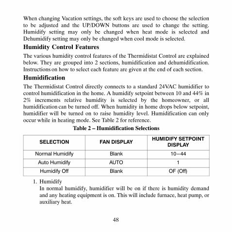
HumidificationThe Thermidistat Control directly connects to a standard 24VAC humidifier tocontrol humidification in the home. A humidify setpoint between 10 and 44% in2% increments relative humidity is selected by the homeowner, or allhumidification can be turned off. When humidity in home drops below setpoint,humidifier will be turned on to raise humidity level. Humidification can onlyoccur while in heating mode. See Table 2 for reference.
Table 2 – Humidification Selections
SELECTION FAN DISPLAYHUMIDIFY SETPOINT
DISPLAY
Normal Humidify Blank 10-44
Auto Humidify AUTO 1
Humidify Off Blank OF (Off)
1. HumidifyIn normal humidify, humidifier will be on if there is humidity demandand any heating equipment is on. This will include furnace, heat pump, orauxiliary heat.

49
2. Auto HumidifyThermidistat Control will automatically adjust the humidity setpointaccording to the outdoor temperature. As the outdoor temperaturedecreases, the humidity setpoint also decreases. Settings ranging from 1 to9, 1 being the lowest and 9 the highest, will be visible to the homeowner.See Fig. 17 for outdoor temperature/indoor humidity relationship in autohumidify mode. Outdoor Air Temperature Sensor must be connected.
3. Humidify OffThe humidify function can be turned off completely. This does notrequire changing existing setpoints.
To Select Humidification (programmable)
Press the soft key below the humidify icon to bring up humidity select screen.Humidify options are only available when in Heating mode. When system is inAUTO mode, humidify options are available if the last system operation was acall for heat.To Select Humidification (non−programmable)
Press the features button twice. The first press displays the outdoor airtemperature and the second press displays the humidity value and humidifytarget.Pressing the mode button shall cycle through the available humidificationselections (Off, Humidify and Auto Humidify).Additional Humidify Comments
The humidifier is actually turned on when humidity is 1% below setpoint andturned off when it reaches 1% above setpoint. This built−in hysteresis preventshumidify output from toggling on and off when humidity level is near setpoint.
50
DehumidificationDehumidification is done only during cooling. Depending on type of equipmentused, compressor speed, blower speed, setpoint adjustment, and equipmentcycling are modified to provide added dehumidification. A dehumidificationsetpoint (separate from humidification setpoint) is available to the homeowner. Itcan range from 46% to 66% relative humidity. When actual humidity is higherthan setpoint, a dehumidification demand exists. The Thermidistat Controlresponds by activating the dry contact (when enabled in Option 19). It may alsocontrol the compressor and blower, depending on equipment type anddehumidify selection choice. The 3 available selections are described below. Amandatory 5 minute blower off delay will be enforced if there has been a call fordehumidification during a cooling call. The amount of extra dehumidificationavailable is very dependent on the type of equipment in the home. Without avariable−speed blower, the system’s ability to adjust dehumidification is verylimited.
1. Normal Dehumidify OperationWhen normal dehumidify is selected, the compressor will not turn onwithout a cooling demand. If dehumidify demand exists while cooling,dry contact will also be active (24VAC removed). This output commandsvariable−speed blowers to reduce their airflow, which improves waterremoval from the cooled air.
2. Cool to DehumidifyThe cool to dehumidify selection tells the system to operate thecompressor, within limits, when there is a dehumidify demand even ifthere is no cooling demand. The limits are that the system may overcoolup to 3�, but no more, while attempting to satisfy a dehumidify demand.Within this 3� range, there is an additional balance between overcoolingand humidity satisfaction. When overcooling must occur, the dehumidify

51
setpoint is adjusted upward by 2% per degree of overcooling. Forexample, a cooling setpoint of 76�F/24�C and a dehumidify setpoint of60% is equivalent to a cooling setpoint of 75�F/24�C and a dehumidifysetpoint of 62%. This dehumidify setpoint change is internal to theThermidistat Control and is not shown on the display.
A06599
Fig. 17 − Auto Humidity
3. Dehumidify OffDehumidification can be turned off completely. This can be done withoutchanging existing setpoints.
52
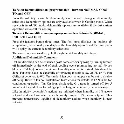
To Select Dehumidification (programmable − between NORMAL, COOLTO, and OFF)
Press the soft key below the dehumidify icon button to bring up dehumidifyselections. Dehumidify options are only available when in Cooling mode. Whensystem is in AUTO mode, dehumidify options are available if the last systemoperation was a call for cooling.To Select Dehumidification (non−programmable − between NORMAL,COOL TO, and OFF)
Press the features button three times. The first press displays the outdoor airtemperature, the second press displays the humidify options and the third presswill display the current dehumidify selections.
The mode button is used to cycle through the dehumidify selections.Additional Dehumidify Comments
Dehumidification can be enhanced (with some efficiency loss) by turning bloweroff immediately at the end of each cooling cycle (eliminating normal 90 secblower off delay). Where maximum humidity removal is desired, this should bedone. Fan coils have the capability of removing this off delay. On FK or FV FanCoils, set delay tap to 0/0. On standard fan coils, a jumper can be cut to disableoff delay. Refer to fan coil Installation Instructions for details. If FAN is set forcontinuous operation (fan On icon displayed), G output is turned off for 5minutes at the end of each cooling cycle as long as dehumidify demand exists.Like humidify, dehumidify actions are initiated when humidity is 1% abovesetpoint and are terminated when humidity drops to 1% below setpoint. Thisprevents unnecessary toggling of dehumidify actions when humidity is nearsetpoint.

53
Dehumidify Output and Equipment Connections
When there is a dehumidify demand, dry contact is activated, meaning that a24VAC signal is removed from the DHUM or DH output terminal. In otherwords, dehumidify output logic is reversed − output is turned On when nodehumidify demand exists and is turned OFF when demand exists.
Carrier FK and FV series variable−speed fan coils, all variable−speed furnaces,and select single and multi−stage furnaces with the dehumidify connection havedehumidify inputs which connect directly to Thermidistat Control dry contact.Refer to the furnace literature for dehumidification options.The FK and FV series fan coils have a terminal marked DH which should beconnected to the Thermidistat Control dry contact output. Jumper J1 on fan coilMUST be removed. It is located behind the DH terminal. Additionally blowerdelay tap on fan coil should be set to 0/0 (no On delay and no OFF delay) whenusing cool to dehumidify. With this selection, the blower stops when G signal isremoved, preventing re−evaporation of water from the coil which would occurduring the normal 90 sec blower off delay. See fan coil installation instructionsfor more information.
The furnace dehumidify input acts differently depending on which style ofvariable speed, select single−stage or multi−stage furnace control you have.
Vacation (programmable models only)A vacation selection is available specifically for times where the home will notbe occupied for an extended period. Vacation mode has an automatic hold,meaning that setpoints are not affected by the programmed schedule. Vacationmode is active for a specified period of time. While in vacation mode, the systemprovides temperature and humidity protection for the home in the selected mode,but not comfort. When vacation mode is active, an arrow will be displayedbeside “VACATION” in the upper left corner of the display.

54
Vacation Setpoints
A special set of temperature and humidity setpoints exist which are active invacation mode. They are adjustable by the homeowner, are exclusively forvacation mode, and are remembered from one vacation selection to the next. SeeTable 3 for default values.
Table 3 – Vacation Setpoints Default Values
MODE AUTO
Fan Auto
Heat Setpoint 55�F/13�C
Cool Setpoint 85�F/29�C
Humidify Setpoint 20�F/−7�C
Dehumidify Setpoint 60�F/16�C
Vacation HumidificationNormal humidify is available using vacation setpoints. Auto humidification isavailable, adjusting its setpoint with outdoor temperature the same as whenoccupied. Vacation humidification can be turned off independently of occupiedhumidification. While setting the Vacation setpoints, the Vacation humidifysetpoint is accessible by pressing the soft key below the humidify icon when thebox is around the heating setpoint.
Vacation Dehumidification
Normal Dehumidify, Cool to Dehumidify, and Dehumidify OFF are all availablein vacation mode, and selection of one of these can be different from that ofoccupied. Vacation dehumidification selection and setpoints are remembered thenext time vacation is used. While setting Vacation setpoints, the Vacation

55
dehumidify setpoint is accessible by pressing the soft key below the dehumidifyicon when the box is around the cooling setpoint.
OPERATIONAL INFORMATIONTimersFive−Minute Compressor Timeguard
This timer prevents compressor from starting unless it has been off for at least 5minutes. It can be overridden for 1 cycle by simultaneously pressing FAN andUP buttons.
Cycle TimerBased on the selection of 2, 4, or 6 cycles per hour, this timer is set to 30, 15, or10 minutes. This much time must elapse from the start of one cycle beforeanother cycle can start. It serves to impose the cycles per hour limits. It can bedefeated for one cycle by simultaneously pressing the FAN and UP buttons.Ten−Minute Staging Timer
In multistage heating or cooling, this timer prevents any higher stage fromturning on until preceding stage has been on for 10 minutes. When stagingbetween compressor and electric heat or between compressor and furnace heat,the time is configurable. The timer is configurable via Option 17. This timer isoverridden if temperature error is greater than 5� (usually due to a large changein desired temperature) and equipment stages up in 60 second intervals.The ten−minute staging timer does not require the thermostat to change to ahigher stage after 10 minutes. If the system is able to meet the demand (maintainsetpoint) it may not change stages after the 10 minute timer has expired. If thereis sufficient demand for a higher stage at the end of 10 minutes or at any timeafter the 10 minute timer has expired, the thermostat will energize the next higherstage.

56
Defrost
When defrost occurs in a Hybrid Heat system, the furnace will operate during thedefrost cycle. At the end of the defrost cycle, the furnace and heat pump will bede−energized while the fan is energized for 2 minutes allowing the heatexchanger to cool down. If Option 34, Hybrid Heat Furnace Latch is set to Off,at the end of the 2 minute time, the heat pump will be re−energized if a call forheat still exists. If Option 34 is set to On (default), the furnace will remain onuntil the end of the heating cycle.
Defrost detection is not available if the installer has configured the O/W2/Boutput to function as a B output. During heat pump heating, a defrost signal shallbe considered valid if the compressor output is energized and the defrost signalhas been active for less than 15 consecutive minutes. Any defrost signal presentfor longer than 15 minutes shall be considered invalid.
Heat pump/fan coil and Hybrid Heat systems shall use this input to:� Detect that defrost is in progress and energize the auxiliary heat to
provide homeowner comfort during the defrost cycle� Allow a defrost cycle to run to completion regardless of the system
demand
Three−Minute Minimum on TimeIn normal operation, when a stage turns on, it will not turn off for a minimum of3 minutes. In Hybrid Heat systems, the minimum on time for the furnace is 5minutes. If the setpoint is changed, this timer is canceled, allowing the equipmentto turn off immediately when the demand is removed. The 3 minute minimumon timer applies to all stages of heating and cooling, except Hybrid Heat. A stagewill run for a minimum of 3 minutes before the thermostat will be allowed tostage to a lower stage.

57
Heat/Cool Setpoints (Desired Temperature)
A minimum difference of 1� and maximum of 6� is enforced between heatingand cooling desired temperatures. This is done by allowing 1 setting to “push”the other, to maintain this difference. This difference is adjustable viaConfiguration Option 11.
Equipment On IndicatorsWhen cooling equipment is on, a COOL ON icon is displayed. While coolingequipment operation is delayed by the time guard or cycle timer, COOL ON willflash. The same is true for HEAT ON icon.
During second stage compressor operation a “2” will be displayed with theHEAT ON or COOL ON icon. This is displayed when the Thermidistat Controlis configured as H2, A2, or h2.
When the W is energized in a heat pump or Hybrid Heat system, the “auxiliaryheat on” icon will be displayed.
Humidify and Dehumidify IndicatorsWhen the Display Module door is closed, the humidify icon will be displayedwhen humidification is active and the dehumidify icon will be displayed whendehumidification is active.
Auto ChangeoverWhen auto changeover mode is selected, a change from heat to cool (or viceversa) will not occur until an opposite mode demand has existed for 20 minutes.If setpoint is changed, 20−minute requirement is deleted.Emergency Heat Mode
When Thermidistat Control is configured as a heat pump and emergency heat isselected, all Y signals are locked out, and W becomes energized upon a call forheat.

58
Programmable Fan (programmable models only)
The fan output can be programmed based on period of the day. Whenprogramming for each day and period the fan can be set to On or AUTO. If thefan button is pressed to change from On to Auto or vice versa whenprogrammable fan has been enabled, the manual change will only remain ineffect until the next program period, when the programmable fan setting will bechanged per the scheduled setting.Dry Contact
On the programmable models, the dry contact that can be used for control of anauxiliary device. The dry contact may be configured to be closed for a specificnumber of minutes per hour for each period of the program schedule. This canbe used to operate a ventilator, damper, system blower, or other auxiliary device.There are two terminals, D1 and D2.On both the programmable and non−programmable models, when configured asa dehumidify output, it will operate cooling equipment capable of dehumidifyfunction. When configured for dehumidification, the Rc terminal must beconnected to one of the dry contact terminals. The other dry contact terminal isconnected to the dehumidify terminal on the furnace or fan coil. This providespower to energize the dehumidify terminal on the cooling equipment when thedry contact is closed.If it is desired to operate a ventilator or other device, the D1 and D2 terminalscan be connected directly to the equipment. This will provide a closed contactfor the specified number of minutes per hour. See Option 19.If timed control of the system blower is required, the dry contact can be used forthis function. The G terminal can be connected to one of the dry contactterminals with the other terminal being connected to Rc and/or Rh for timedcontrol of the fan. Note that this is not the same as programmable fan Option 30.

59
See Wiring Diagrams for more information.
RelaysThis thermostat uses latching relays. When the thermostat loses power, the relayswill remain in their last position until power is restored and all relays are reset totheir correct position. Out of the box, the outputs may appear to be On when thethermostat is not powered. This is normal. Output states should only be checkedwhen the thermostat is powered.Temperature Offset After Power Cycle
To compensate for internal heat build−up from the electronics in the thermostat,the thermostat will add an offset to the actual temperature that it measures. If thethermostat power is cycled quickly, one can witness an immediate increase in theactual temperature displayed due to this added offset. The thermostat display willreturn to the actual room temperature after several minutes of operation.

60
TROUBLESHOOTINGIf the display module doesn’t power up after power is applied, check the Rc/Rhand C terminals for 24VAC. If 24VAC is present, check the voltage between Vgand V+. This voltage will be approximately 12−20VDC. If voltage is present,check the polarity to make sure it is wired correctly. The display will not powerup if polarity is reversed.If dashes appear for Option 01 in config and during reboot, the problem could bethe red pigtail being wired to Rc or Rh and the black pigtail being wired to C. Ifso, remove the two−wire pigtail and connect to the V+ and Vg terminals.
Error Codes“−−” − If Thermidistat Control cannot properly read room temperature, displaywill indicate “−−” and all outputs (except fan, if on) will turn off. In the casewhere the installer has selected to average the local sensor and the remote roomsensor, the Thermidistat Control display will alternate between “−−” for thefailed sensor and the temperature sensed by the working sensor every 10seconds. The control will operate from the temperature sensed by the workingsensor.E1 − If the Display Module and the Equipment Control Module cannotcommunicate via two−wire connection, an E1 will be displayed.E2 − There is no E2 error message.E3 − If Thermidistat Control cannot properly read outdoor temperature, and it isneeded for proper operation, display will indicate “−−” in the outdoortemperature location. If Option 06, 08, 09, 22, 23 or 44 is not set to OFF, displaywill indicate “−−” in the outdoor temperature location.E4 − If Thermidistat Control’s internal memory fails, E4 will be displayed.Replace Thermidistat Control.
61
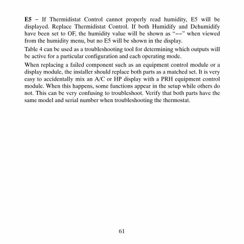
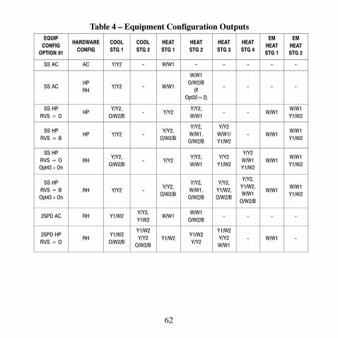
E5 − If Thermidistat Control cannot properly read humidity, E5 will bedisplayed. Replace Thermidistat Control. If both Humidify and Dehumidifyhave been set to OF, the humidity value will be shown as “−−” when viewedfrom the humidity menu, but no E5 will be shown in the display.Table 4 can be used as a troubleshooting tool for determining which outputs willbe active for a particular configuration and each operating mode.
When replacing a failed component such as an equipment control module or adisplay module, the installer should replace both parts as a matched set. It is veryeasy to accidentally mix an A/C or HP display with a PRH equipment controlmodule. When this happens, some functions appear in the setup while others donot. This can be very confusing to troubleshoot. Verify that both parts have thesame model and serial number when troubleshooting the thermostat.
62
Table 4 – Equipment Configuration OutputsEQUIP
CONFIGOPTION 01
HARDWARECONFIG
COOLSTG 1
COOLSTG 2
HEATSTG 1
HEATSTG 2
HEATSTG 3
HEATSTG 4
EMHEATSTG 1
EMHEATSTG 2
SS AC AC Y/Y2 - W/W1 - - - - -
SS ACHPRH
Y/Y2 - W/W1
W/W1O/W2/B
(ifOpt32�2)
- - - -
SS HPRVS � O
HPY/Y2,
O/W2/B- Y/Y2
Y/Y2,W/W1
- - W/W1W/W1Y1/W2
SS HPRVS � B
HP Y/Y2 -Y/Y2,
O/W2/B
Y/Y2,W/W1,
O/W2/B
Y/Y2W/W1/Y1/W2
- W/W1W/W1Y1/W2
SS HPRVS � OOpt43 = On
RHY/Y2,
O/W2/B- Y/Y2
Y/Y2,W/W1
Y/Y2Y1/W2
Y/Y2W/W1Y1/W2
W/W1W/W1Y1/W2
SS HPRVS � B
Opt43 = OnRH Y/Y2 -
Y/Y2,O/W2/B
Y/Y2,W/W1,
O/W2/B
Y/Y2,Y1/W2,O/W2/B
Y/Y2,Y1/W2,W/W1
O/W2/B
W/W1W/W1Y1/W2
2SPD AC RH Y1/W2Y/Y2,Y1W2
W/W1W/W1
O/W2/B- - - -
2SPD HPRVS � O
RHY1/W2
O/W2/B
Y1/W2Y/Y2
O/W2/BY1/W2
Y1/W2Y/Y2
Y1/W2Y/Y2W/W1
- W/W1 -

63
Table 4 − Equipment Configuration Outputs (cont.)EQUIP
CONFIGOPTION 01
HARDWARECONFIG
COOLSTG 1
COOLSTG 2
HEATSTG 1
HEATSTG 2
HEATSTG 3
HEATSTG 4
EMHEATSTG 1
EMHEATSTG 2
2SPD HPRVS � B
RH Y1/W2Y1/W2Y/Y2
Y1/W2O/W2/B
Y1/W2Y/Y2
O/W2/B
Y1/W2Y/Y2
O/W2/BW/1
- W/W1 -
SS HybridHeat
RVS � ORH
Y/Y2,O/W2/B
- Y/Y2 W/W1W/W1Y1/W2
- W/W1W/W1Y1/W2
SS HybridHeat
RVS � BRH Y/Y2 -
Y/Y2O/W2/B
W/W1 - - W/W1 -
2S HybridHeat
RVS � ORH
Y1/W2O/W2/B
Y1/W2Y/Y2
O/W2/BY1/W2
Y1/W2Y/Y2
W/W1 - W/W1 -
2S HybridHeat
RVS � BRH Y1/W2
Y1/W2Y/Y2
Y1/W2O/W2/B
Y1/W2Y/Y2
O/W2/BW/W1 - W/W1 -
Heat OnlyUnit
ACHPRH
- - W/W1
If HP or2S board
ANDOpt32 � 2
- - - -
Cool OnlyUnit
RH Y1/W2Y1/W2Y/Y2
- - - - - -
Cool OnlyUnit
ACHP
Y/Y2 - - - - - - -

64
WIRING DIAGRAMSDisplay module
Display modulewall mount Equipment Control Module Fan Coil Heat Pump
V+ V+
Vg Vg O O
V+ RVS/Heat Stage 2 O/B W2 W3 W2
Vg Heat Stage 1 W/W1 W2
Compressor Y/Y2 Y Y
Y1 / W2
Fan G G
24VAC Hot Heating Rh R R
24VAC Hot Cooling Rc
Dry Contact 1 D1
Dry Contact 2 D2
24VAC Common C C C
Outdoor Air Temp OAT
Remote Room Sensor RRS
OAT/RRS Com SRTN
Outdoor Sensor *
Remote Room Sensor *
V+
Vg
* Indicates connection may not be required/available.
A09163
Fig. 18 − Display to Equipment Control Module Connection

65
Equipment Control Module Fan Coil Heat Pump
O O
RVS Cooling O/B W2 W1 W1
Heat Stage 3 W/W1 W2
Heat/Cool Stage 1 Y1 / W2 Y1 Y1
Heat/Cool Stage 2 Y/Y2 Y/Y2 Y/Y2
Fan G G
24VAC Hot Heating Rh R R
24VAC Hot Cooling Rc Remove J1jumper forDehumidifymodes
Dry Contact 1 D1
Dry Contact 2 D2 DH
24VAC Common C C C
Humidify HUM
Outdoor Air Temp OAT
Remote Room Sensor RRS
OAT/RRS Com SRTN
Outdoor Sensor *
Humidifier Solenoid Valve *
Remote Room Sensor *
* Indicates connection may not be required/available.
A09657
Fig. 19 − FV/FK Fan Coil with 2−Stage Heat Pump

66
Typical Single-StageEquipment Control Module Fan Coil Heat Pump
O
RVS Cooling O/B W2 E W2
Heat Stage 2 W/W1 W2
Heat Stage 3 Y1 / W2 W3
Heat/Cool Stage 1 Y/Y2 Y
Fan G G
24VAC Hot Heating Rh R R
24VAC Hot Cooling Rc
Dry Contact 1 D1
Dry Contact 2 D2
24VAC Common C C C
Humidify HUM
Outdoor Air Temp OAT
Remote Room Sensor RRS
OAT/RRS Com SRTN
Outdoor Sensor *
Humidifier Solenoid Valve *
Remote Room Sensor *
* Indicates connection may not be required/available.
A09165
Fig. 20 − Typical Fan Coil with Heat Pump

67
Equipment Control Module
RVS/Heat Stage 2 O/B W2 W3
Heat Stage 1 W/W1 W2
Compressor Low Y1 / W2
Compressor High Y/Y2
Fan G G
24VAC Hot Heating Rh R
24VAC Hot Cooling Rc
Dry Contact 1 D1
Dry Contact 2 D2 Aux. Connection
24VAC Common C C
Humidify HUM
Outdoor Air Temp OAT
Remote Room Sensor RRS
OAT/RRS Com SRTN
Outdoor Sensor *
Humidifier Solenoid Valve *
Remote Room Sensor *
* Indicates connection may not be required/available.
A09166
Fig. 21 − Fan Coil Shown w/Aux. Connection #1(Heat Pump/Air Conditioner removed for clarity.)

68
Equipment Control Module Fan Coil Air Conditioner
ORemove J2Jumper forheat staging
Heat Stage 2 O/B W2 W2
Heat Stage 1 W/W1 W1
Cool Stage 1 Y1 / W2 Y1 Y1
Cool Stage 2 Y/Y2 Y/Y2 Y2
Fan G G
24VAC Hot Heating Rh R R
24VAC Hot Cooling Rc Remove J1jumper forDehumidifymodes
Dry Contact 1 D1
Dry Contact 2 D2 DH
24VAC Common C C C
Humidify HUM
Outdoor Air Temp OAT
Remote Room Sensor RRS
OAT/RRS Com SRTN
Outdoor Sensor *
Humidifier Solenoid Valve *
Remote Room Sensor *
* Indicates connection may not be required/available.
A09167
Fig. 22 − FV/FK Fan Coil w/2−Stage Air Conditioner
69
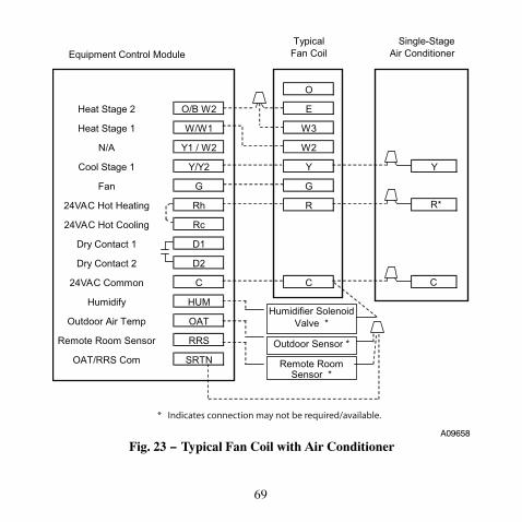
Typical Single-StageEquipment Control Module Fan Coil Air Conditioner
O
Heat Stage 2 O/B W2 E
Heat Stage 1 W/W1 W3
N/A Y1 / W2 W2
Cool Stage 1 Y/Y2 Y Y
Fan G G
24VAC Hot Heating Rh R R*
24VAC Hot Cooling Rc
Dry Contact 1 D1
Dry Contact 2 D2
24VAC Common C C C
Humidify HUM
Outdoor Air Temp OAT
Remote Room Sensor RRS
OAT/RRS Com SRTNOutdoor Sensor *
Humidifier Solenoid Valve *
Remote Room Sensor *
* Indicates connection may not be required/available.
A09658
Fig. 23 − Typical Fan Coil with Air Conditioner

70
Equipment Control Module Fan Coil
RVS/Heat Stage 2 O/B W2 W3
Heat Stage 1 W/W1 W2
Compressor Low Y1 / W2
Compressor High Y/Y2
Fan G G
24VAC Hot Heating Rh R
24VAC Hot Cooling Rc
Dry Contact 1 D1
Dry Contact 2 D2 Aux. Connection
24VAC Common C C
Humidify HUM
Outdoor Air Temp OAT
Remote Room Sensor RRS
OAT/RRS Com SRTN
Outdoor Sensor *
Humidifier Solenoid Valve *
Remote Room Sensor *
* Indicates connection may not be required/available.
A09169
Fig. 24 − Fan Coil Shown with Aux. Connection #2(Heat Pump/Air Conditioner removed for clarity.)

71
Equipment Control Module Fan Coil Heat Pump
O O
RVS Cooling O/B W2 W2
Heat Stage 2 W/W1 W1 Remove J2Jumper forheat stagingHeat Stage 3 Y1 / W2 W2
Heat/Cool Stage 1 Y/Y2 Y/Y2 Y
Fan G G
24VAC Hot Heating Rh R R
24VAC Hot Cooling Rc Y1 Remove J1Jumper forDehumidifymodes
Dry Contact 1 D1
Dry Contact 2 D2 DH
24VAC Common C C C
Humidify HUM
Outdoor Air Temp OAT
Remote Room Sensor RRS
OAT/RRS Com SRTN
Outdoor Sensor *
Humidifier Solenoid Valve *
Remote Room Sensor *
* Indicates connection may not be required/available.
A09170
Fig. 25 − FV/FK Fan Coil with 1−Stage Heat Pump

72
TypicalEquipment Control Module Fan Coil
RVS/Heat Stage 2 O/B W2 E
Heat Stage 1 W/W1 W2
Compressor Low Y1 / W2
Compressor High Y/Y2
Fan G G
24VAC Hot Heating Rh R
24VAC Hot Cooling Rc
Dry Contact 1 D1
Dry Contact 2 D2
24VAC Common C C
Humidify HUM
Outdoor Air Temp OAT
Remote Room Sensor RRS
OAT/RRS Com SRTN
Outdoor Sensor *
Humidifier Solenoid Valve *
Remote Room Sensor *
* Indicates connection may not be required/available.
A09171
Fig. 26 − Typical Fan Coil Heating Only

73
Equipment Control Module
RVS/Heat Stage 2 O/B W2
Heat Stage 1 W/W1
Compressor Low Y1 / W2
Compressor High Y/Y2
Fan G G
24VAC Hot Heating Rh R
24VAC Hot Cooling Rc
Dry Contact 1 D1
Dry Contact 2 D2
24VAC Common C C
Humidify HUM
Outdoor Air Temp OAT
Remote Room Sensor RRS
OAT/RRS Com SRTN
A09172
Fig. 27 − Thermidistat Control w/Dry Contact Control for Fan Run Time

74
Equipment Control Module Fan Coil Air Conditioner
O
Heat Stage 2 O/B W2 W2 Remove J2Jumper forheat stagingHeat Stage 1 W/W1 W1
N/A Y1 / W2 Y1
Heat/Cool Stage 1 Y/Y2 Y/Y2 Y
Fan G G
24VAC Hot Heating Rh R R*
24VAC Hot Cooling Rc Remove J1Jumper forDehumidifymodes
Dry Contact 1 D1
Dry Contact 2 D2 DH
24VAC Common C C C
Humidify HUM
Outdoor Air Temp OAT
Remote Room Sensor RRS
OAT/RRS Com SRTN
Outdoor Sensor *
Humidifier Solenoid Valve *
Remote Room Sensor *
* Indicates connection may not be required/available.
A09659
Fig. 28 − FV/FK Fan Coil with 1−Stage Air Conditioner

75
Typical Single-StageEquipment Control Module Fan Coil Air Conditioner
RVS/Heat Stage 2 O/B W2
Heat Stage 1 W/W1
Compressor Low Y1 / W2
Compressor High Y/Y2 Y
Fan G G
24VAC Hot Heating Rh R R*
24VAC Hot Cooling Rc
Dry Contact 1 D1
Dry Contact 2 D2
24VAC Common C C C
Humidify HUM
Outdoor Air Temp OAT
Remote Room Sensor RRS
OAT/RRS Com SRTN
Outdoor Sensor *
Humidifier Solenoid Valve *
Remote Room Sensor *
* Indicates connection may not be required/available.
A09660
Fig. 29 − Typical Fan Coil Cooling Only

76
Equipment Control Module Furnace Heat Pump
O
RVS Cooling O/B W2 W2
Heat Stage 3 (furnace) W/W1 W/W1 W2**
Heat/Cool Stage 1 Y1 / W2 Y1
Heat/Cool Stage 2 Y/Y2 Y/Y2 Y/Y2
Fan G G
24VAC Hot Heating Rh R R
24VAC Hot Cooling Rc
Dry Contact 1 D1
Dry Contact 2 D2 DHUM
24VAC Common C COM C
Humidify HUM
Outdoor Air Temp OAT
Remote Room Sensor RRS
OAT/RRS Com SRTN
Outdoor Sensor *
Humidifier Solenoid Valve *
Remote Room Sensor *
Y1
***
* Indicates connection may not be required/available.** Some heat pumps may designate W1.***Option 19 set to 2.
A09121
Fig. 30 − Variable Speed, Multi−Stage, Stage Modulating and Single−StageFurnace with 2−Stage Heat Pump

77
Single-StageEquipment Control Module Furnace Heat Pump
O
RVS Cooling O/B W2
Heat Stage 2 (furnace) W/W1 W W2**
Y1 / W2
Heat/Cool Stage 1 Y/Y2 Y/Y2 Y
Fan G G
24VAC Hot Heating Rh R R
24VAC Hot Cooling Rc
Dry Contact 1 D1
Dry Contact 2 D2 DHUM
24VAC Common C COM C
Humidify HUM
Outdoor Air Temp OAT
Remote Room Sensor RRS
OAT/RRS Com SRTN
Outdoor Sensor *
Humidifier Solenoid Valve *
Remote Room Sensor *
Y1
HUM ***
* Indicates connection may not be required/available.** Some heat pumps may designate W1.***Option 19 set to 2.
Heat Stage 2
A09618
Fig. 31 − Single−Stage Furnace with Heat Pump(Hybrid Heat)

78
Equipment Control Module Furnace Air Conditioner
Heat Stage 2 O/B W2 W2
Heat Stage 1 W/W1 W/W1
Cool Stage 1 Y1 / W2 Y1
Cool Stage 2 Y/Y2 Y/Y2 Y/Y2
Fan G G
24VAC Hot Heating Rh R R
24VAC Hot Cooling Rc
Dry Contact 1 D1
Dry Contact 2 D2 DHUM
24VAC Common C COM C
Humidify HUM
Outdoor Air Temp OAT
Remote Room Sensor RRS
OAT/RRS Com SRTN
Outdoor Sensor *
Humidifier Solenoid Valve *
Remote Room Sensor *
Y1
* Indicates connection may not be required/available.
A09123
Fig. 32 − Variable Speed, Step Modulating, Multi−Stage and Single−StageFurnace with Two−Stage Air Conditioner

79
Single-StageEquipment Control Module Furnace Air Conditioner
N/A O/B W2
Heat Stage 1 W/W1 W
N/A Y1 / W2
Cool Stage 1 Y/Y2 Y/Y2 Y
Fan G G
24VAC Hot Heating Rh R R*
24VAC Hot Cooling Rc
Dry Contact 1 D1
Dry Contact 2 D2 DHUM
24VAC Common C COM C
Humidify HUM
Outdoor Air Temp OAT
Remote Room Sensor RRS
OAT/RRS Com SRTNOutdoor Sensor *
Humidifier Solenoid Valve *
Remote Room Sensor *
Y1
**
* Indicates connection may not be required/available.** Option 19 set to 2.
A09661
Fig. 33 − Single−Stage Furnace with Single−Speed Air Conditioner

80
Equipment Control Module Furnace Heat Pump
O
RVS Cooling O/B W2 W2 W2**
Heat Stage 3 (furnace) Y1 / W2 W/W1
Heat Stage 2 (furnace) W/W1 Y1
Heat/Cool Stage 1 Y/Y2 Y/Y2 Y
Fan G G
24VAC Hot Heating Rh R R
24VAC Hot Cooling Rc
Dry Contact 1 D1
Dry Contact 2 D2 DHUM
24VAC Common C COM C
Humidify HUM
Outdoor Air Temp OAT
Remote Room Sensor RRS
OAT/RRS Com SRTN
Outdoor Sensor *
Humidifier Solenoid Valve *
Remote Room Sensor *
***
* Indicates connection may not be required/available.** Some heat pumps may designate W1.***Option 19 set to 2.
A09125
Fig. 34 − Variable Speed, Multi−Stage and Step Modulating Furnace withSingle−Stage Heat Pump

81
Equipment Control Module Furnace
N/A O/B W2
Heat Stage 1 W/W1 W
N/A Y1 / W2
N/A Y/Y2
Fan G G
24VAC Hot Heating Rh R
24VAC Hot Cooling Rc
Dry Contact 1 D1
Dry Contact 2 D2 DHUM
24VAC Common C COM
Humidify HUM
Outdoor Air Temp OAT
Remote Room Sensor RRS
OAT/RRS Com SRTN
Outdoor Sensor *
Humidifier Solenoid Valve *
Remote Room Sensor *
* Indicates connection may not be required/available.
A09126
Fig. 35 − Single−Stage Furnace Heating Only
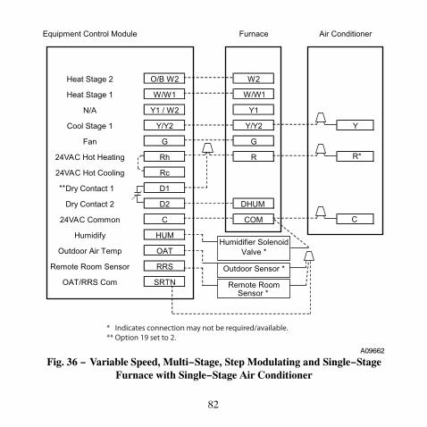
82
Equipment Control Module Furnace Air Conditioner
Heat Stage 2 O/B W2 W2
Heat Stage 1 W/W1 W/W1
N/A Y1 / W2 Y1
Cool Stage 1 Y/Y2 Y/Y2 Y
Fan G G
24VAC Hot Heating Rh R R*
24VAC Hot Cooling Rc
Dry Contact 1 D1
Dry Contact 2 D2 DHUM
24VAC Common C COM C
Humidify HUM
Outdoor Air Temp OAT
Remote Room Sensor RRS
OAT/RRS Com SRTN
Outdoor Sensor *
Humidifier Solenoid Valve *
Remote Room Sensor *
**
* Indicates connection may not be required/available.** Option 19 set to 2.
A09662
Fig. 36 − Variable Speed, Multi−Stage, Step Modulating and Single−StageFurnace with Single−Stage Air Conditioner
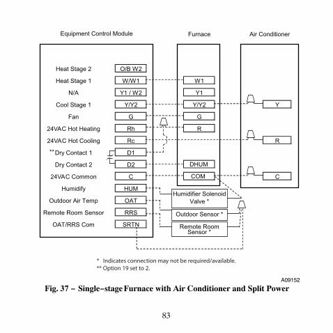
83
Furnace Air Conditioner
Heat Stage 2 O/B W2
Heat Stage 1 W/W1 W1
N/A Y1 / W2 Y1
Cool Stage 1 Y/Y2 Y/Y2 Y
Fan G G
24VAC Hot Heating Rh R
24VAC Hot Cooling Rc R
Dry Contact 1 D1
Dry Contact 2 D2 DHUM
24VAC Common C COM C
Humidify HUM
Outdoor Air Temp OAT
Remote Room Sensor RRS
OAT/RRS Com SRTN
Outdoor Sensor *
Humidifier Solenoid Valve *
Remote Room Sensor *
**
Equipment Control Module
* Indicates connection may not be required/available.** Option 19 set to 2.
A09152
Fig. 37 − Single−stage Furnace with Air Conditioner and Split Power

84
THERMIDISTAT CONTROL CONFIGURATIONRECORD
Installer_________________________
Model Number______________________________
Date_________________________
A. Hardware Configuration
__________ Seal Hole In Wall
B. Mode Settings
__________ Mode (Off, Heat, Cool, Auto, Em Heat)
__________ Heating Setpoint Value
__________ Cooling Setpoint Value
__________ Fan (Auto or On)
C. Home, Away, Sleep Settings
Heat Cool
Home ____
____
Away ____
____
Sleep ____
____
D. Schedule (For Programmable Thermidistat Controls)
Period 1 Period 2 Period 3 Period 4
Time Heat Cool Time Heat Cool Time Heat Cool Time Heat Cool
All Days ____
____
____
____
____
____
____
____
____
____
____
____
Weekdays ____
____
____
____
____
____
____
____
____
____
____
____
Weekend ____
____
____
____
____
____
____
____
____
____
____
____
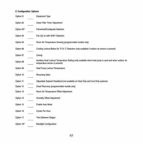
85
E Configuration Options
Option 01 _____
Equipment Type
Option 02 _____
Clean Filter Timer Adjustment
Option 03* _____
Fahrenheit/Centigrade Selection
Option 04 _____
Fan (G) on with W/W1 Selection
Option 05 _____
Room Air Temperature Sensing (programmable models only)
Option 06 _____
Cooling Lockout Below 55�F/13�C Selection (only available if outdoor air sensor is present)
Option 07 _____
Zoning
Option 08 _____
Auxiliary Heat Lockout Temperature Setting (only available when heat pump is used and when outdoor airtemperature sensor is present)
Option 09 _____
Heat Pump Lockout Temperature
Option 10 _____
Reversing Valve
Option 11 _____
Adjustable Setpoint Deadband (not available on Heat Only and Cool Only systems)
Option 12 _____ Smart Recovery (programmable models only)
Option 13 _____
Room Air Temperature Offset Adjustment
Option 14 _____
Humidity Offset Adjustment
Option 15 _____
Enable Auto Mode
Option 16 _____
Cycles Per Hour
Option 17 _____
Time Between Stages
Option 18* _____
Backlight Configuration

86
E Configuration Options (cont)
Option 19 _____
Dry Contact (programmable models only)
Option 20 _____
Outdoor Air Temperature Offset Adjustment
Option 21* _____
Keypad Lockout
Option 22 _____
High Cool Latch Temperature
Option 23 _____
High Heat Latch Temperature
Option 24* _____
Programmable/Non-Programmable (programmable models only)
Option 25* _____
Number of Programmable Periods Per Day (programmable models only)
Option 26 _____
Minimum Cooling Setpoint
Option 27 _____
Maximum Heating Setpoint
Option 28 _____
UV Light Reminder
Option 29 _____
Humidifier Pad Reminder
Option 30* _____
Programmable Fan (programmable models only)
Option 31* _____
Daylight Savings Time Configuration (programmable models only)
Option 32 _____
Furnace Heat Staging
Option 33 _____
Single or Two-Piece Installation
Option 34 _____
Hybrid Heat Furnace Latch

87
E Configuration Options (cont)
Option 40 _____
Fan Humidity
Option 41 _____
Variable Speed Blower
Option 42 _____
Variable Speed Super Dehumidification
Option 43 _____
Intelligent Heat Staging
Option 44 _____
Super Comfort Heat
Option 99 _____
Reset to Factory Defaults
* Options with an asterisk can also be set/changed by the homeowner.

88
Copyright 2010 Carrier Corp. � 7310 W. Morris St. � Indianapolis, IN 46231Printed in U.S.A. Edition Date: 01/10
Manufacturer reserves the right to change, at any time, specificationsand designs without notice and without obligations. Replaces: TP-PRH-4SI
Catalog No: TP-PRH-05SI