installation instructions evacuated tube solar water heaters range... · 1.7 the solar collector...
TRANSCRIPT

Solar Group Limited – 0800 447 336 | Page 1
Installation Instructions
Evacuated Tube Solar Water Heaters
GreenGlo water heaters are AS/NZ 2712:2007 certified. They are known for their exceptional performance and longevity. Please read the following instructions carefully to ensure their correct installation for optimum results.
If you have any questions please call us on 0800 447 336
This document was printed as per March 2013 requirements and may not be the latest document.
Solar Group Limited – 0800 447 336 | Page 2
GreenGlo Evacuated tube solar system – installation manual
This assembly manual covers assembly of the frame (if needed), roof mounting of the 20 and 30 tube evacuated solar tube collectors and installation to the cylinder.
Contents
Page
3 Section 1
Specifications and cautions
7 Section 2
General guidelines for roof-mounting of the solar collectors
8 Section 3
Collector assembly
10 Section 4
Frame assembly when collector angle needs to be greater than the roof pitch
11 Section 5
Roof fixings
12 Section 6
Roof Support
13 Section 7
Plumbing
14 Section 8
Electrical
14 Section 9
Finishing off
16 Section 10
Common Issues
17 Section 11
Limitations and Clauses
18 Section 12
Installer checklist
Commissioning with Customer
Ask customer to be available at the end of the day/estimated completion time for commissioning and to go through the paperwork.
Otherwise this can be discussed by phone or if another appointment is necessary a call out fee may be applied.
Please make sure you have the appropriate Council specific PS3 and any other paperwork required by the local council to leave on site with the consent documents.
Solar Group Limited – 0800 447 336 | Page 3
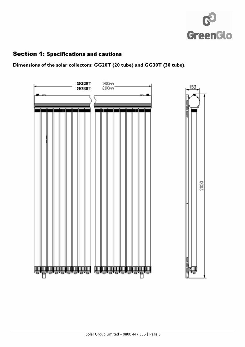
Section 1: Specifications and cautions
Dimensions of the solar collectors: GG20T (20 tube) and GG30T (30 tube).
Solar Group Limited – 0800 447 336 | Page 4
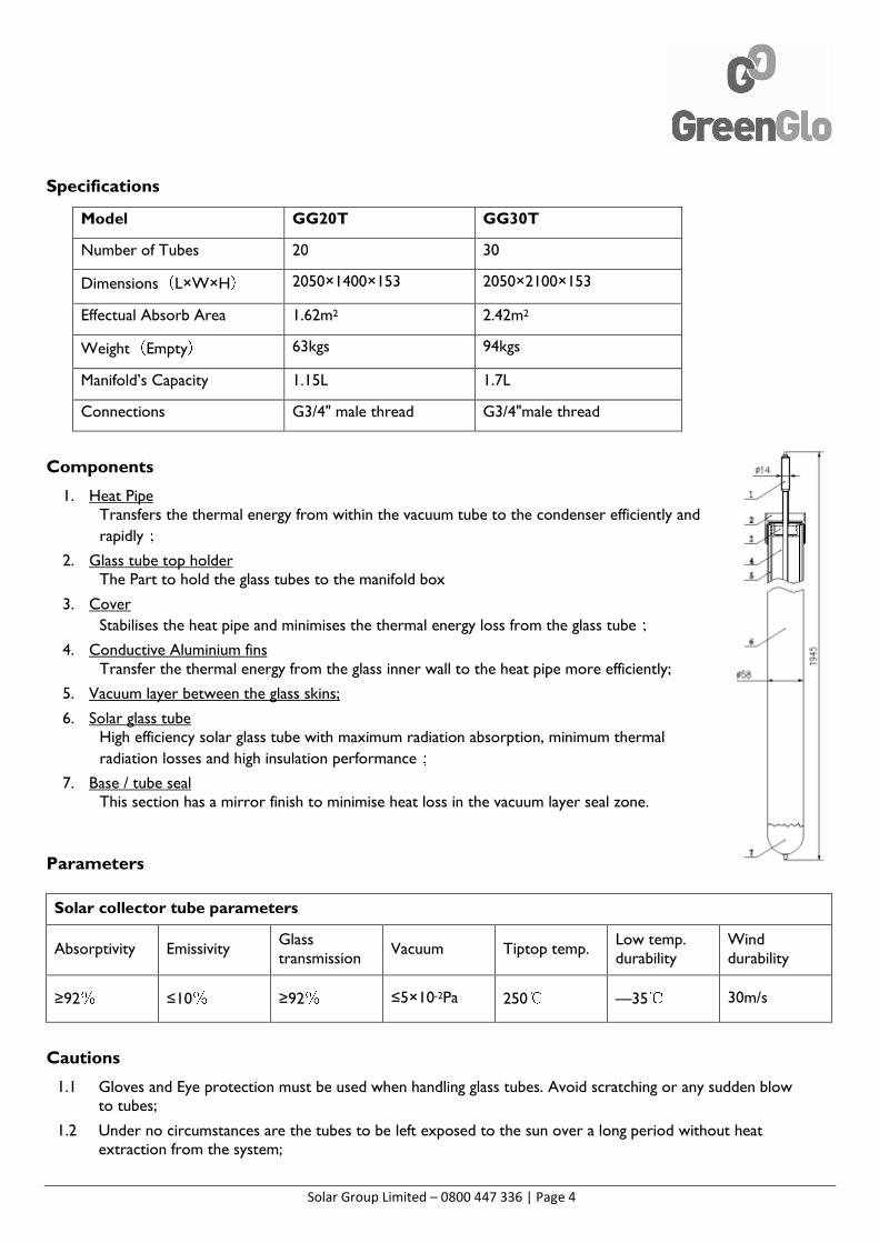
Specifications
Model GG20T GG30T
Number of Tubes 20 30
Dimensions(L×W×H) 2050×1400×153 2050×2100×153
Effectual Absorb Area 1.62m2 2.42m2
Weight(Empty) 63kgs 94kgs
Manifold’s Capacity 1.15L 1.7L
Connections G3/4" male thread G3/4"male thread
Components
1. Heat Pipe Transfers the thermal energy from within the vacuum tube to the condenser efficiently and
rapidly;
2. Glass tube top holder The Part to hold the glass tubes to the manifold box
3. Cover
Stabilises the heat pipe and minimises the thermal energy loss from the glass tube;
4. Conductive Aluminium fins Transfer the thermal energy from the glass inner wall to the heat pipe more efficiently;
5. Vacuum layer between the glass skins;
6. Solar glass tube High efficiency solar glass tube with maximum radiation absorption, minimum thermal
radiation losses and high insulation performance;
7. Base / tube seal This section has a mirror finish to minimise heat loss in the vacuum layer seal zone.
Parameters
Solar collector tube parameters
Absorptivity Emissivity Glass transmission
Vacuum Tiptop temp. Low temp. durability
Wind durability
≥92% ≤10% ≥92% ≤5×10⁻²Pa 250℃ —35℃ 30m/s
Cautions
1.1 Gloves and Eye protection must be used when handling glass tubes. Avoid scratching or any sudden blow to tubes;
1.2 Under no circumstances are the tubes to be left exposed to the sun over a long period without heat extraction from the system;
Solar Group Limited – 0800 447 336 | Page 5
1.3 Unpack and install tubes after the manifold unit has been installed and all pipe work has been completed and
the system is filled.(Avoid high temperature of empty manifold to affect system efficiency);
1.4 During installation of the tubes, the pump should be switched on;
1.5 If the system is out of use for a long time, the solar collector must be covered over / shaded with a suitable screen;
1.6 Apply locally applicable Health and Safety guidelines at all time;
1.7 The solar collector should be installed within 22°~~~~500 angle.
1.8 The weight bearing capacity of the roof MUST be calculated for the maximum collector weight, the load-bearing points and the rafter size / strength;
1.9 When heating a swimming pool or spa, a heat exchanger should be used between the pool and the collector.
1.10 GreenGlo manifolds are designed to operate at a maximum pressure of 6 Bar (90psi). It’s strongly recommended to use a suitable pressure relief valve.
1.11 To extend the service life of your system, the vacuum tubes should not be installed until the system is fully connected and ready for use.
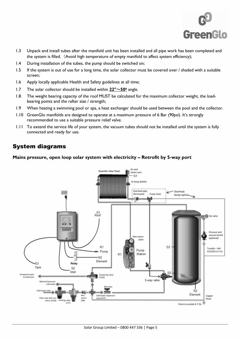
System diagrams
Mains pressure, open loop solar system with electricity – Retrofit by 5-way port
Solar Group Limited – 0800 447 336 | Page 6
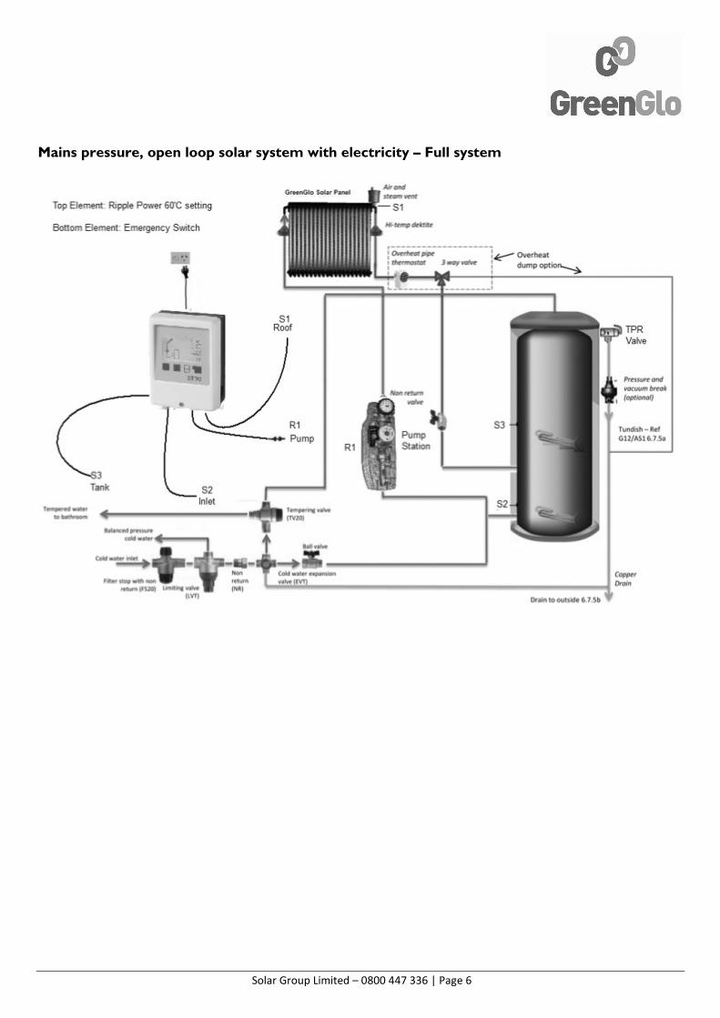
Mains pressure, open loop solar system with electricity – Full system
Solar Group Limited – 0800 447 336 | Page 7
Section 2: General guidelines for roof-mounting of the solar collectors
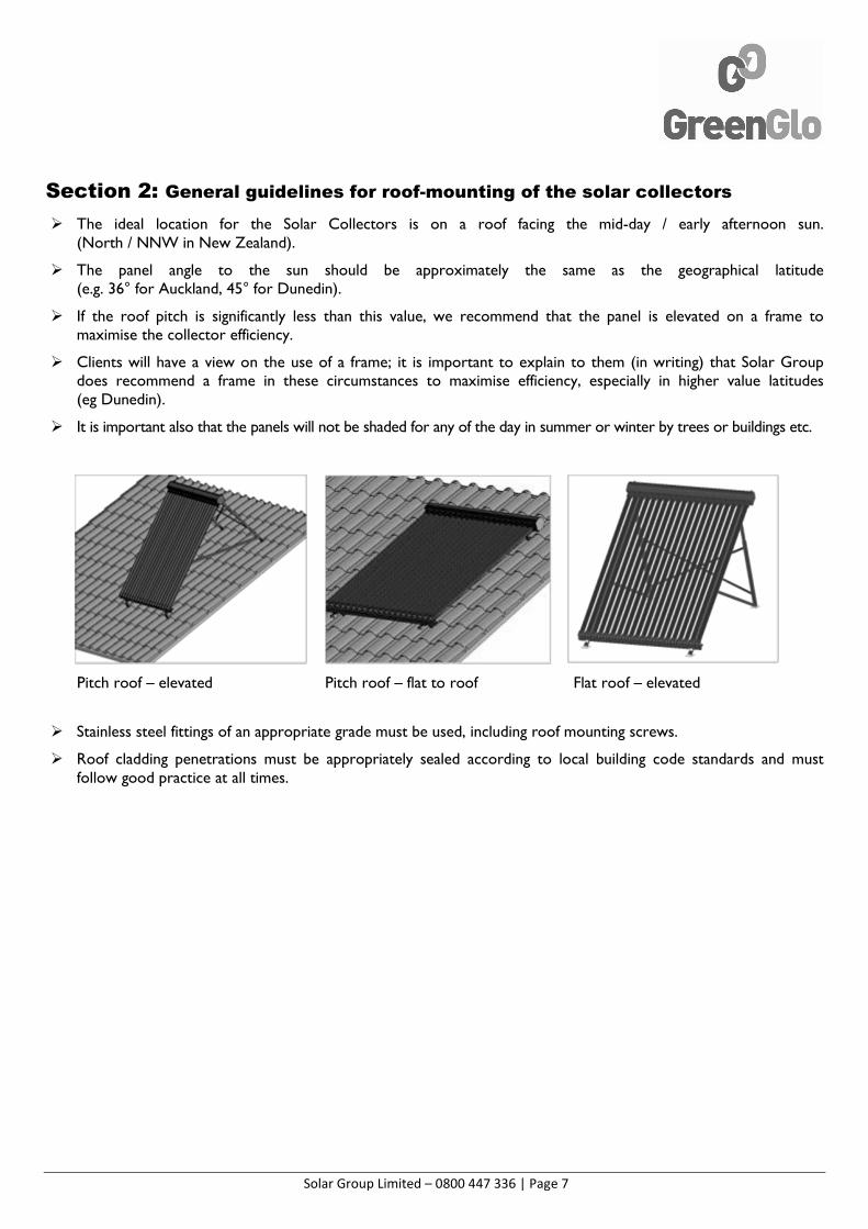
� The ideal location for the Solar Collectors is on a roof facing the mid-day / early afternoon sun. (North / NNW in New Zealand).
� The panel angle to the sun should be approximately the same as the geographical latitude (e.g. 36° for Auckland, 45° for Dunedin).
� If the roof pitch is significantly less than this value, we recommend that the panel is elevated on a frame to maximise the collector efficiency.
� Clients will have a view on the use of a frame; it is important to explain to them (in writing) that Solar Group does recommend a frame in these circumstances to maximise efficiency, especially in higher value latitudes (eg Dunedin).
� It is important also that the panels will not be shaded for any of the day in summer or winter by trees or buildings etc.
Pitch roof – elevated Pitch roof – flat to roof Flat roof – elevated
� Stainless steel fittings of an appropriate grade must be used, including roof mounting screws.
� Roof cladding penetrations must be appropriately sealed according to local building code standards and must follow good practice at all times.
Solar Group Limited – 0800 447 336 | Page 8
Section 3: Collector assembly
Before beginning, make sure you have all the pieces required;
• 2-3 boxes of 10 evacuated tubes (depending if it is a GG20T or GG30T).
• 1 box containing the manifold, bottom track, end cups, stainless steel clips and a small brass fitting.
• 1 box containing the vertical tracks.
• Flat roof stand if required – refer to page 9 for diagram.
Assembling the frame
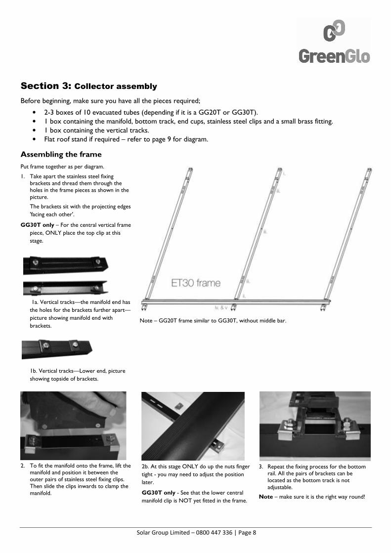
Put frame together as per diagram.
1. Take apart the stainless steel fixing brackets and thread them through the holes in the frame pieces as shown in the picture.
The brackets sit with the projecting edges
'facing each other'.
GG30T only – For the central vertical frame
piece, ONLY place the top clip at this
stage.
1a. Vertical tracks—the manifold end has
the holes for the brackets further apart—
picture showing manifold end with
brackets.
1b. Vertical tracks—Lower end, picture
showing topside of brackets.
Note – GG20T frame similar to GG30T, without middle bar.
2. To fit the manifold onto the frame, lift the manifold and position it between the outer pairs of stainless steel fixing clips. Then slide the clips inwards to clamp the manifold.
2b. At this stage ONLY do up the nuts finger
tight - you may need to adjust the position
later.
GG30T only - See that the lower central
manifold clip is NOT yet fitted in the frame.
3. Repeat the fixing process for the bottom rail. All the pairs of brackets can be located as the bottom track is not adjustable.
Note – make sure it is the right way round!
Solar Group Limited – 0800 447 336 | Page 9
Finalising position
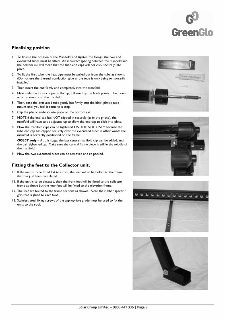
1. To finalise the position of the Manifold, and tighten the fixings, the two end evacuated tubes must be fitted. An incorrect spacing between the manifold and the bottom rail will mean that the tube end caps will not click securely into place.
2. To fit the first tube, the heat pipe must be pulled out from the tube as shown. (Do not use the thermal conduction glue as the tube is only being temporarily installed).
3. Then insert the end firmly and completely into the manifold.
4. Next slide the loose copper collar up, followed by the black plastic tube mount which screws onto the manifold.
5. Then, ease the evacuated tube gently but firmly into the black plastic tube mount until you feel it come to a stop.
6. Clip the plastic end-cap into place on the bottom rail.
7. NOTE if the end-cap has NOT clipped in securely (as in the photo), the manifold will have to be adjusted up to allow the end cap to click into place.
8. Now the manifold clips can be tightened ON THIS SIDE ONLY because the tube end cap has clipped securely over the evacuated tube; in other words the manifold is correctly positioned on the frame.
GG30T only – At this stage, the last central manifold clip can be added, and the pair tightened up. Make sure the central frame piece is still in the middle of the manifold!
9. Now the two evacuated tubes can be removed and re-packed.
Fitting the feet to the Collector unit;
10. If the unit is to be fitted flat to a roof, the feet will all be bolted to the frame that has just been completed.
11. If the unit is to be elevated, then the front feet will be fitted to the collector frame as above but the rear feet will be fitted to the elevation frame.
12. The feet are bolted to the frame sections as shown. Note the rubber spacer / grip that is glued to each foot.
13. Stainless steel fixing screws of the appropriate grade must be used to fix the units to the roof.
Solar Group Limited – 0800 447 336 | Page 10
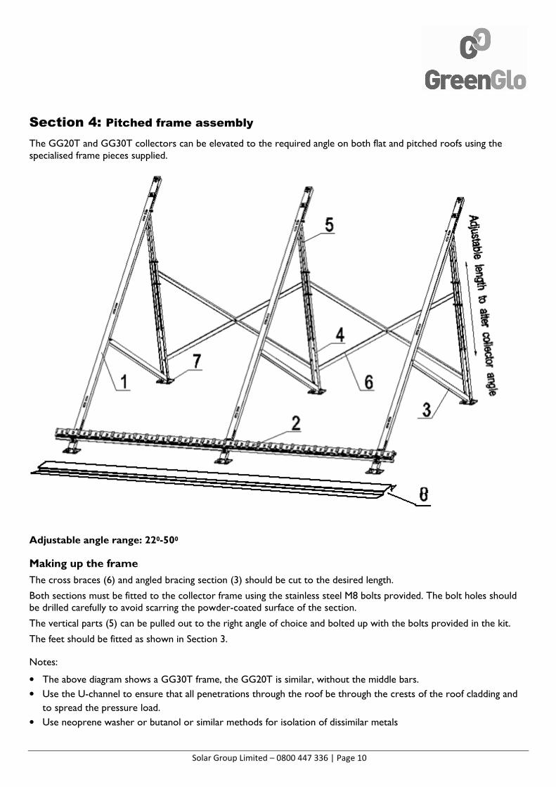
Section 4: Pitched frame assembly
The GG20T and GG30T collectors can be elevated to the required angle on both flat and pitched roofs using the specialised frame pieces supplied.
Adjustable angle range: 220-500
Making up the frame
The cross braces (6) and angled bracing section (3) should be cut to the desired length.
Both sections must be fitted to the collector frame using the stainless steel M8 bolts provided. The bolt holes should be drilled carefully to avoid scarring the powder-coated surface of the section.
The vertical parts (5) can be pulled out to the right angle of choice and bolted up with the bolts provided in the kit.
The feet should be fitted as shown in Section 3.
Notes:
• The above diagram shows a GG30T frame, the GG20T is similar, without the middle bars.
• Use the U-channel to ensure that all penetrations through the roof be through the crests of the roof cladding and
to spread the pressure load.
• Use neoprene washer or butanol or similar methods for isolation of dissimilar metals
Solar Group Limited – 0800 447 336 | Page 11
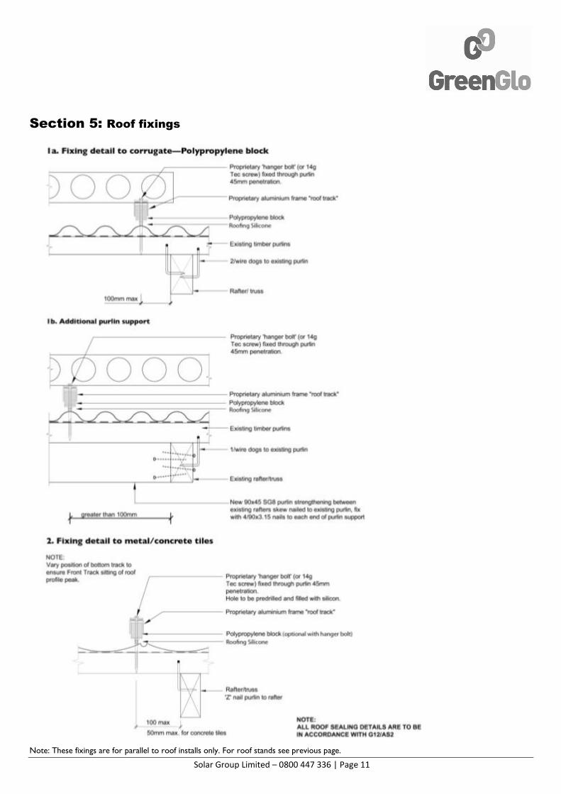
Section 5: Roof fixings
Note: These fixings are for parallel to roof installs only. For roof stands see previous page.
Solar Group Limited – 0800 447 336 | Page 12
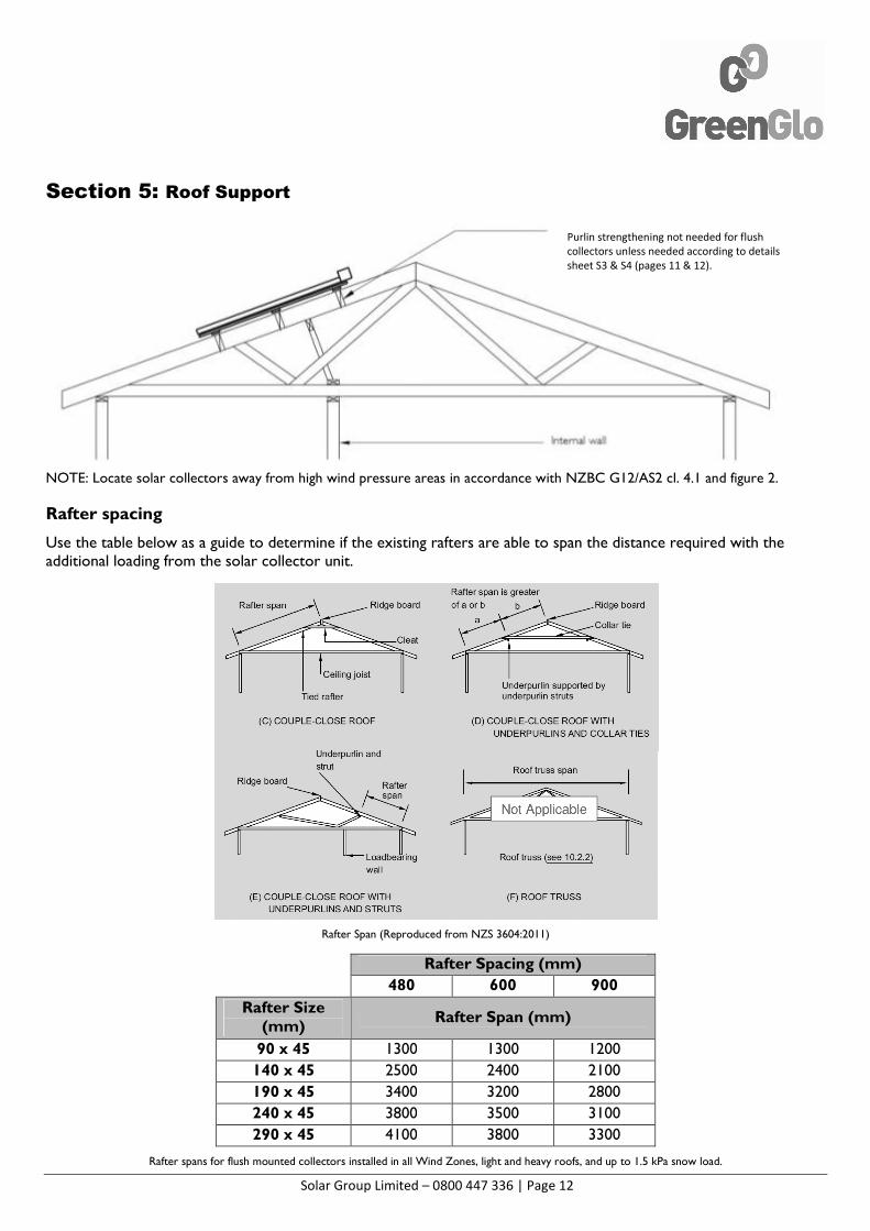
Section 5: Roof Support
NOTE: Locate solar collectors away from high wind pressure areas in accordance with NZBC G12/AS2 cl. 4.1 and figure 2.
Rafter spacing
Use the table below as a guide to determine if the existing rafters are able to span the distance required with the additional loading from the solar collector unit.
Rafter Span (Reproduced from NZS 3604:2011)
Rafter Spacing (mm)
480 600 900
Rafter Size (mm)
Rafter Span (mm)
90 x 45 1300 1300 1200
140 x 45 2500 2400 2100
190 x 45 3400 3200 2800
240 x 45 3800 3500 3100
290 x 45 4100 3800 3300
Rafter spans for flush mounted collectors installed in all Wind Zones, light and heavy roofs, and up to 1.5 kPa snow load.
Purlin strengthening not needed for flush
collectors unless needed according to details
sheet S3 & S4 (pages 11 & 12).
Solar Group Limited – 0800 447 336 | Page 13
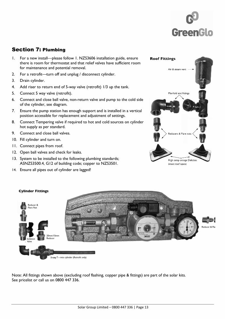
Section 7: Plumbing
1. For a new install—please follow 1. NZS3606 installation guide, ensure there is room for thermostat and that relief valves have sufficient room for maintenance and potential removal.
2. For a retrofit—turn off and unplug / disconnect cylinder.
3. Drain cylinder.
4. Add riser to return end of 5-way valve (retrofit) 1/3 up the tank.
5. Connect 5 way valve (retrofit).
6. Connect and close ball valve, non-return valve and pump to the cold side of the cylinder, see diagram.
7. Ensure the pump station has enough support and is installed in a vertical position accessible for replacement and adjustment of settings.
8. Connect Tempering valve if required to hot and cold sources on cylinder hot supply as per standard.
9. Connect and close ball valves.
10. Fill cylinder and turn on.
11. Connect pipes from roof.
12. Open ball valves and check for leaks.
13. System to be installed to the following plumbing standards; ASNZS3500.4, G12 of building code; copper to NZS3501.
14. Ensure all pipes out of cylinder are lagged!
Note: All fittings shown above (excluding roof flashing, copper pipe & fittings) are part of the solar kits. See pricelist or call us on 0800 447 336.
Solar Group Limited – 0800 447 336 | Page 14
Section 8: Electrical
Use controller manual supplied for detailed instructions; also refer to plumbing & electrical schematic on pages 2&3 of this guide.
1. Mount controller (and relay for retrofits).
2. Attach probes S3 at top and S2 at bottom of cylinder(s) (top connect behind insulation ½ way from top of cylinder, bottom thermocouple often is best behind insulation touching copper by thermostat / element) – New systems will have specific probe pockets.
3. Ensure probe pockets are free of moisture. Use probe grommet or silicone to stop water getting into pocket.
4. Ensure good connection between probe and inside of cylinder.
5. Connect pump using 3-pin plug.
6. (Electrician) Connect controller to element via single pole relay if not a solar cylinder – supply must not be subject to ripple control.
7. Connect power to controller – relay is a switch, do NOT connect an outside live to relay.
8. Switch on and test.
9. For overheat dump option connect pipe thermostat, (live comes from P1 connection) and 3-way valve.
10. Program controller – see system controller booklet
11. For a solar cylinder use only the top element and connect direct to the mains (not through the controller) on all day rate / ripple power
Section 9: Finishing Off
1. Purge pipe and pump of air.
2. Set the flow speed 2.5 litre/min per 10 tubes.
3. Pressure test for leaks by opening to operating pressure and running the pump.
4. Install tubes into manifold use the white heat transfer paste supplied.
5. Fit exterior insulation – so that no bare copper or brass is showing.
6. UV protect the insulation if not already protected by using PVC tape, cover red dektite.
7. Program the controller. Full description for setup options and maintenance given in the controller manual supplied. Also see the next page.
8. Debrief and review settings with customer.
9. Fill out paper work, CoC’s and PS3’s for council.
10. Clean up the site from boxes, wires, etc.
11. Complete Installer Checklist. (Appendix 2/Page 14)
Ensure cups are open
Solar Group Limited – 0800 447 336 | Page 15
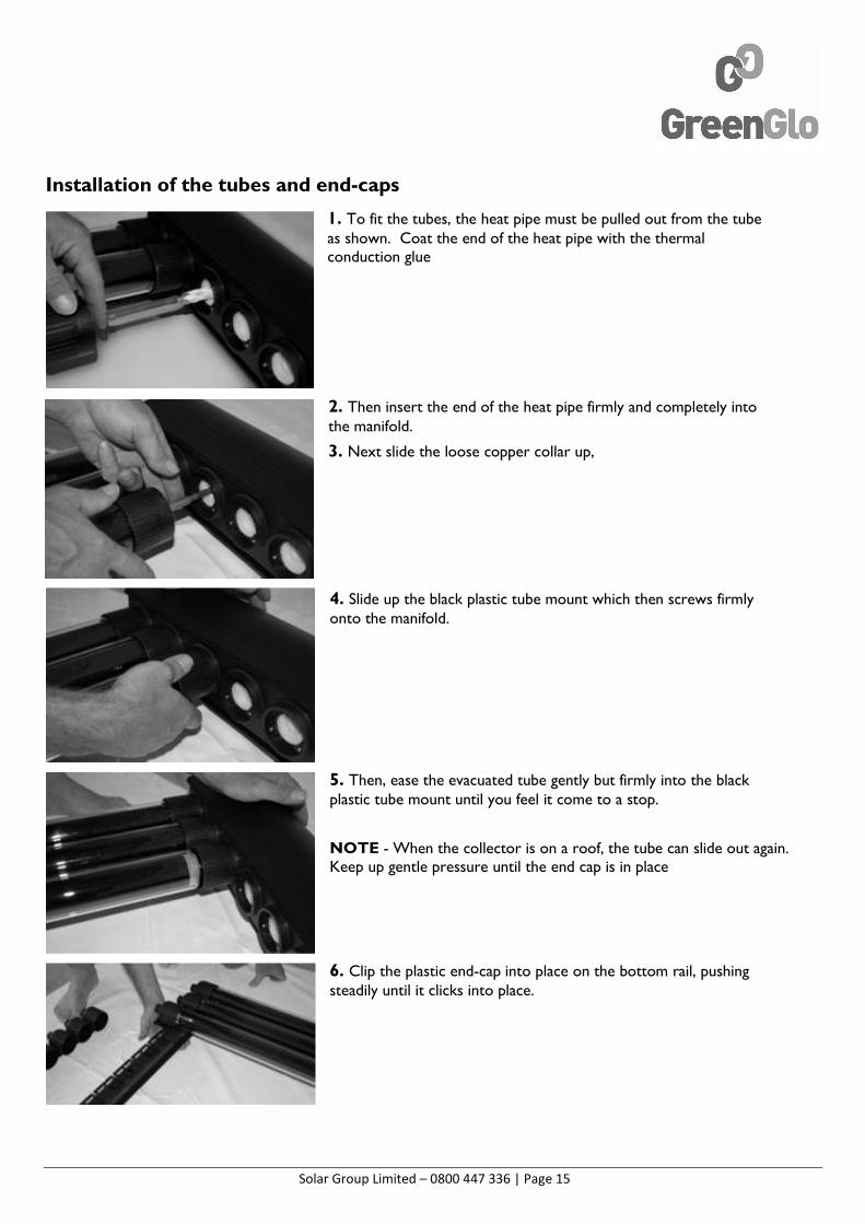
Installation of the tubes and end-caps
1. To fit the tubes, the heat pipe must be pulled out from the tube as shown. Coat the end of the heat pipe with the thermal conduction glue
2. Then insert the end of the heat pipe firmly and completely into the manifold.
3. Next slide the loose copper collar up,
4. Slide up the black plastic tube mount which then screws firmly onto the manifold.
5. Then, ease the evacuated tube gently but firmly into the black plastic tube mount until you feel it come to a stop.
NOTE - When the collector is on a roof, the tube can slide out again. Keep up gentle pressure until the end cap is in place
6. Clip the plastic end-cap into place on the bottom rail, pushing steadily until it clicks into place.
Solar Group Limited – 0800 447 336 | Page 16
Section 10: Common Issues
1. No hot water:
a. Check element is switched on at the wall.
b. Check if power company turned the ripple power off
c. Check that the fuse in the thermostat has not popped – may need to replace with auto-reset thermostat, reduce SMX by 5˚C.
d. Check the timing for the element is on for long enough – most cylinders require 6 hours of heating.
e. Check shower flow rate is not too high – may require flow meter.
2. System not performing as well as expected
a. Check non-return valve is installed and working, check not thermos phoning at night. (Temp at night should be similar to ambient) – may require a second NRV.
3. Boiling on the roof but not heating cylinder
a. Check the flow meter rate
b. No flow - bleed pump if making loud noise, is pump connected vertically?
c. Check there is no high spots above the solar (will create a steam block) – use steam vent. (AAV).
d. Check steam vent is working.
e. Check pump is on fast enough speed.
4. System flooding through house (not that common)
a. This has mostly happened where heat has got through to Polypropylene pipe and melted it. Ensure that copper is used where this can occur. (NB heat can travel up the cold supply pipe when the whole cylinder is HOT.) May require thermal trap on the cold supply (bare copper pipe in a loop).
b. Check that the heat dump at the TPR valve can drain away without backing up and flooding – may require flow restrictor in heat dump loop.
5. Cylinder making banging noise
a. Due to cylinder expansion through heat. Ensure that a cold water expansion valve and a hot water TPR valve are fitted and working. Reduce CWE valve to 6 bar.
6. Sensor Error.
a. Check that the screw into the wire at the control box is screwed into the wire and not the plastic.
b. To check if a wire fault, switch with a dummy sensor.
7. Funny temperature readings
a. Check the right sensor is used in the right position. PT1000 (grey) for TDC and SolaStat for Plus2 controllers (black)
8. Element not coming up to 60C
a. Check probe contact with cylinder and allow 8°C for losses.
b. Check timing and temp of heating program.
c. Check clock time, check night rate and ripple control potential conflicts with timers.
9. Night circulation from cylinder to panel—due to controller not reaching pump off Temp differential
a. Improve connection with Inlet Probe.
b. Check if the Recooling function is ON
10. Too much hot water—system is always boiling
a. Remove tubes.
b. Install heat dump loop.
c. Turn ON Recooling function.
d. Look at heating timing.
Solar Group Limited – 0800 447 336 | Page 17
Section 11: Liitations and clauses — required for AS2712:2007 2.9.1
A. The solar water heater, parts and fittings are usable up to 10 bar pressure / 1000kPA.
The system is made of copper so pool levels of chlorine are not acceptable for use.
For levels of high lime content please check the element in cylinder is incalloy otherwise GreenGlo panels are capable of handling poor water quality.
B. I The water heater will be installed in accordance with AS/NZS3500.4 including insulation and piping.
Copper piping should be used only, throughout install as per attached instructions.
II Cylinders to be installed so to allow for draining of system, water expansion and relief of vacuum as per AS/NZS3500.4.
III Drain trays to be installed as per AS/NZS3500.4, where required.
IV N/a.
V In case of hard water buildup of lime may occur on hot areas, ensure element type is suitable for the water type otherwise softening of water may be required.
C. The system is designed for level 1 and 2 frost protection, if in areas of long term below zero temperatures a closed loop system is advised.
D. Guards to the collectors may be required in areas of vandalism or large hail zones.
E. In areas of cyclonic conditions specific engineering design is required; refer to Installation Handbook rev B for limitations. Panels weigh 18.8kg/m2 when fill of water.
F. For full installation including roof structure spacing please refer to Engineering Installation manual, purlin tables etc. Solar to be installed as to not compromise the structural integrity of the building.
G. Ensure appropriate fixings per roof type as contained in this manual, for roof types outside of these then refer to engineering manual otherwise specific engineer design required.
H. Controller manual to be supplied to customer (which has a boost instruction highlighted).
I. Controller manual to be supplied with the default (printed settings of the thermostats).
J. Follow the finishing off instructions contained for commissioning of the system.
K. Ensure that all systems have an appropriately solar capable tempering valve and this is set to 55C or 45C for elderly, schools and preschools applications. We recommend a 20mm + tempering valve for all low pressure applications.
Solar Group Limited – 0800 447 336 | Page 18
Section 12: Important Checklist for Installer
To complete and tick before leaving site
Please ask customer to be available at the end of the day/estimated completion time for commissioning and to go through the paperwork.
Otherwise this can be discussed by phone or if another appointment is necessary a call out fee may be applied.
Important Checks
Check for leaks
Ensure probes have good contact
Ensure pump works
Check heating element switches on and off
Controller programmed
System debrief with customer and review controller settings
Clean up the site from boxes, wires, etc.
Important Paperwork
Complete Code of Compliance for council
Complete Council specific PS3 documentation
Fill out EECA Grant Claim form and go through with customer
Complete warrantee details in Owner’s Manual
Leave system manuals for customer
Electrical CoC form left with customer documents
If commissioning is not possible because the customer is absent please leave your contact details to make another time or discuss via a phone call.
Dear Customer
Unfortunately in your absence we were unable to go over some of the paperwork and commission your system with you. If you would like to discuss anything further please call me to make a time or go over these on the phone. Please note if another appointment is necessary a call out fee may be applied.
Installer: Date:
Notes: Phone: