installation manual rinnai evacuated tube split solar hot ... · installation manual rinnai...
TRANSCRIPT
Installation ManualRinnai Evacuated Tube
Split Solar Hot Water Systems
This system shall be installed in accordance with:
• Manufacturer’s Installation Instructions• Current AS/NZS 3500
• All applicable local rules and regulations including local OH&S requirements
This system must be installed, commissioned and serviced by an Authorised Person.
Not suitable as a pool or spa heater.
The solar hot and solar cold pipes between the solar storage tank and the solar collectors must be suited to the high water temperatures and pressures that may occur. As such, plastic pipe must not be used. Components used to join pipes must use metallic materials to achieve sealing.
Issue
3
IMPORTANTAS/NZS 2712Lic No.1849SAI Global
Rinnai 2 EVT Collector IM
TABLE OF CONTENTSTABLE OF CONTENTSSpecifications� 3
Evacuated Tube Solar Collector ������������������������������������������������������������������������������������������������������������������������ 3
Installation�information� 5
Regulations and Occupation Health and Safety (OH&S) ���������������������������������������������������������������������������������� 5
System Orientation and Inclination ��������������������������������������������������������������������������������������������������������������������� 5
Water Quality ������������������������������������������������������������������������������������������������������������������������������������������������������ 5
Water Pipes, Fittings and Insulation ������������������������������������������������������������������������������������������������������������������� 6
Roof Mounting Options ��������������������������������������������������������������������������������������������������������������������������������������� 6
Mounting Location Suitability ����������������������������������������������������������������������������������������������������������������������������� 7
Installation�-�Evacuated�Tubes� 9
Components ������������������������������������������������������������������������������������������������������������������������������������������������������� 9
Assemble Base Frame ������������������������������������������������������������������������������������������������������������������������������������� 13
Installation on a Pitched Tile Roof �������������������������������������������������������������������������������������������������������������������� 14
Installation on a Pitched Metal Roof ����������������������������������������������������������������������������������������������������������������� 15
Installation on a Flat Roof Frame �������������������������������������������������������������������������������������������������������������������� 16
Fitting the Evacuated Tubes ����������������������������������������������������������������������������������������������������������������������������� 18
Joining Two Collectors ������������������������������������������������������������������������������������������������������������������������������������� 19
Plumbing Connections and Temperature Sensor ��������������������������������������������������������������������������������������������� 19
This manual covers the installation of Rinnai evacuated tube solar collectors as part of a complete solar hot water systems�
Full instructions can be found in the “Operation / Installation Manual - Rinnai Split Solar Hot Water Systems”� This manual is provided in the pump kit� Issue 11 and above of this manual provide relevant information for systems using evacuated tube collectors� If you have an older version please obtain the latest version from www�rinnai�com�au�
All information and warnings in the “Operation / Installation Manual - Rinnai Split Solar Hot Water Systems” are applicable to this installation�
Rinnai 3 EVT Collector IM
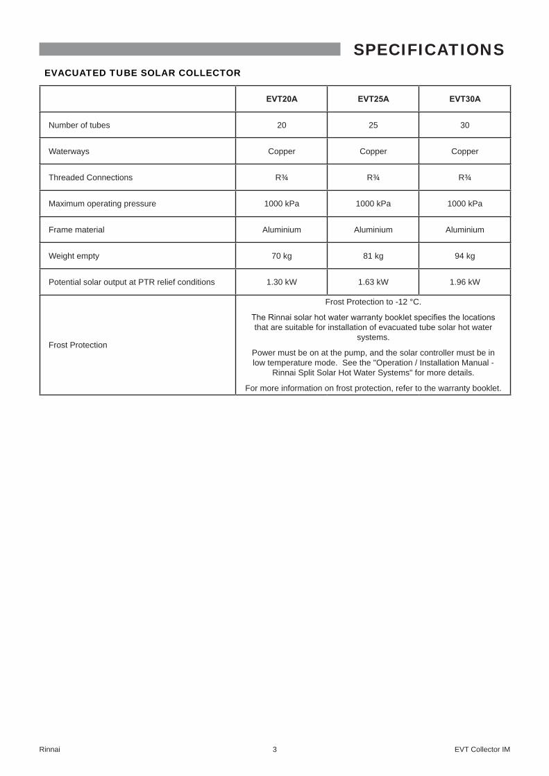
EVACUATED TUBE SOLAR COLLECTOR
EVT20A EVT25A EVT30A
Number of tubes 20 25 30
Waterways Copper Copper Copper
Threaded Connections R¾ R¾ R¾
Maximum operating pressure 1000 kPa 1000 kPa 1000 kPa
Frame material Aluminium Aluminium Aluminium
Weight empty 70 kg 81 kg 94 kg
Potential solar output at PTR relief conditions 1�30 kW 1�63 kW 1�96 kW
Frost Protection
Frost Protection to -12 °C�
The Rinnai solar hot water warranty booklet specifies the locations that are suitable for installation of evacuated tube solar hot water
systems�
Power must be on at the pump, and the solar controller must be in low temperature mode� See the "Operation / Installation Manual -
Rinnai Split Solar Hot Water Systems" for more details�
For more information on frost protection, refer to the warranty booklet�
SPECIFICATIONS
Rinnai 4 EVT Collector IM
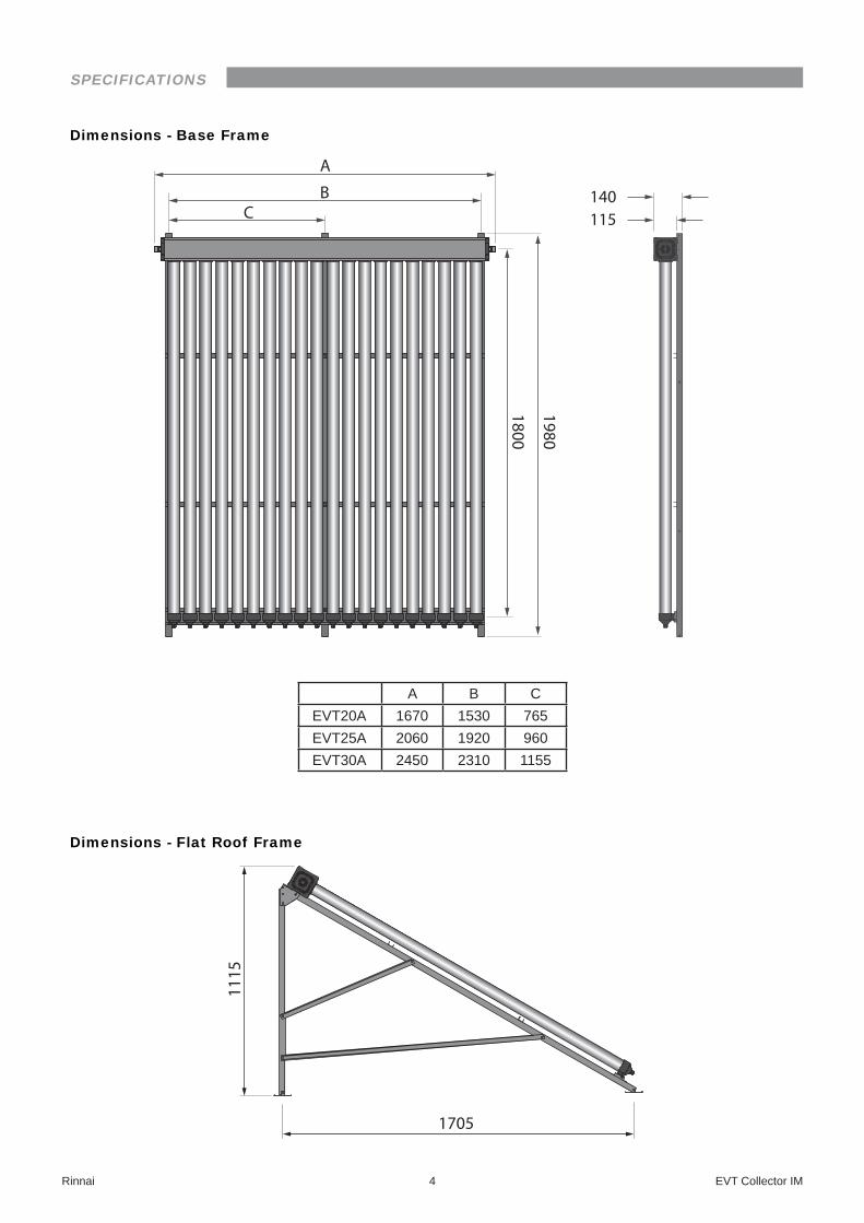
Dimensions - Base Frame
A
BC 115
140
1980
1800
A B CEVT20A 1670 1530 765EVT25A 2060 1920 960EVT30A 2450 2310 1155
Dimensions - Flat Roof Frame
1705
1115
SPECIFICATIONS
Rinnai 5 EVT Collector IM
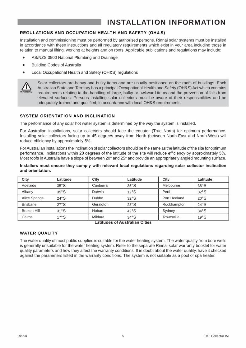
REGULATIONS AND OCCUPATION HEALTH AND SAFETY (OH&S)
Installation and commissioning must be performed by authorised persons� Rinnai solar systems must be installed in accordance with these instructions and all regulatory requirements which exist in your area including those in relation to manual lifting, working at heights and on roofs� Applicable publications and regulations may include:
• AS/NZS 3500 National Plumbing and Drainage
• Building Codes of Australia
• Local Occupational Health and Safety (OH&S) regulations
WARNING
Solar collectors are heavy and bulky items and are usually positioned on the roofs of buildings� Each Australian State and Territory has a principal Occupational Health and Safety (OH&S) Act which contains requirements relating to the handling of large, bulky or awkward items and the prevention of falls from elevated surfaces� Persons installing solar collectors must be aware of their responsibilities and be adequately trained and qualified, in accordance with local OH&S requirements.
SYSTEM ORIENTATION AND INCLINATION
The performance of any solar hot water system is determined by the way the system is installed�
For Australian installations, solar collectors should face the equator (True North) for optimum performance� Installing solar collectors facing up to 45 degrees away from North (between North-East and North-West) will reduce efficiency by approximately 5%.
For Australian installations the inclination of solar collectors should be the same as the latitude of the site for optimum performance. Inclinations within 20 degrees of the latitude of the site will reduce efficiency by approximately 5%. Most roofs in Australia have a slope of between 20° and 25° and provide an appropriately angled mounting surface�
Installers�must�ensure�they�comply�with�relevant� local�regulations�regarding�solar�collector� inclination�and�orientation.�
City Latitude City Latitude City LatitudeAdelaide 35°S Canberra 35°S Melbourne 38°SAlbany 35°S Darwin 12°S Perth 32°SAlice Springs 24°S Dubbo 32°S Port Hedland 20°SBrisbane 27°S Geraldton 28°S Rockhampton 24°SBroken Hill 31°S Hobart 42°S Sydney 34°SCairns 17°S Mildura 34°S Townsville 19°S
Latitudes�of�Australian�Cities
WATER QUALITY
The water quality of most public supplies is suitable for the water heating system� The water quality from bore wells is generally unsuitable for the water heating system� Refer to the separate Rinnai solar warranty booklet for water quality parameters and how they affect the warranty conditions� If in doubt about the water quality, have it checked against the parameters listed in the warranty conditions� The system is not suitable as a pool or spa heater�
INSTALLATION INFORMATION
Rinnai 6 EVT Collector IM
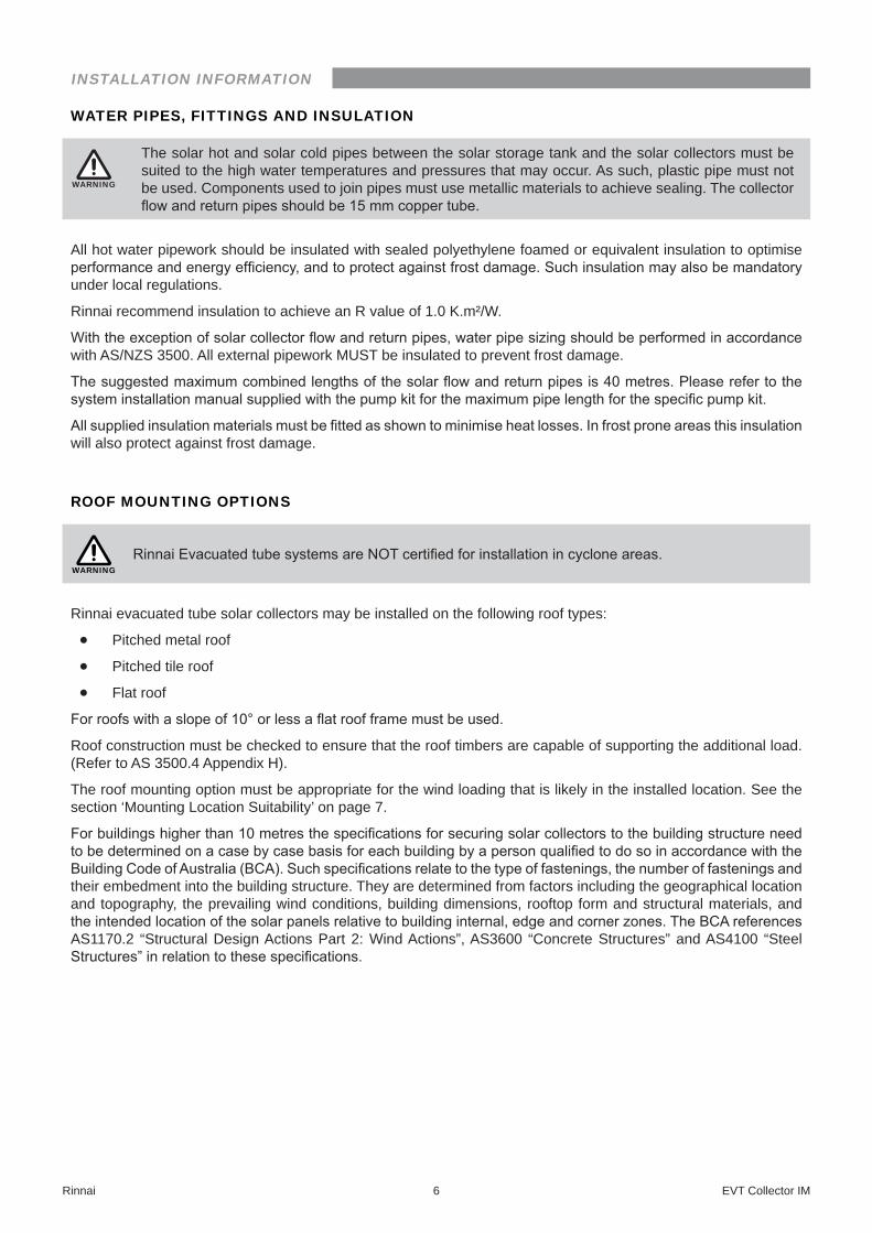
WATER PIPES, FITTINGS AND INSULATION
WARNING
The solar hot and solar cold pipes between the solar storage tank and the solar collectors must be suited to the high water temperatures and pressures that may occur� As such, plastic pipe must not be used� Components used to join pipes must use metallic materials to achieve sealing� The collector flow and return pipes should be 15 mm copper tube.
All hot water pipework should be insulated with sealed polyethylene foamed or equivalent insulation to optimise performance and energy efficiency, and to protect against frost damage. Such insulation may also be mandatory under local regulations�
Rinnai recommend insulation to achieve an R value of 1�0 K�m²/W�
With the exception of solar collector flow and return pipes, water pipe sizing should be performed in accordance with AS/NZS 3500� All external pipework MUST be insulated to prevent frost damage�
The suggested maximum combined lengths of the solar flow and return pipes is 40 metres. Please refer to the system installation manual supplied with the pump kit for the maximum pipe length for the specific pump kit.
All supplied insulation materials must be fitted as shown to minimise heat losses. In frost prone areas this insulation will also protect against frost damage�
ROOF MOUNTING OPTIONS
WARNINGRinnai Evacuated tube systems are NOT certified for installation in cyclone areas.
Rinnai evacuated tube solar collectors may be installed on the following roof types:
• Pitched metal roof
• Pitched tile roof
• Flat roof
For roofs with a slope of 10° or less a flat roof frame must be used.
Roof construction must be checked to ensure that the roof timbers are capable of supporting the additional load� (Refer to AS 3500�4 Appendix H)�
The roof mounting option must be appropriate for the wind loading that is likely in the installed location� See the section ‘Mounting Location Suitability’ on page 7�
For buildings higher than 10 metres the specifications for securing solar collectors to the building structure need to be determined on a case by case basis for each building by a person qualified to do so in accordance with the Building Code of Australia (BCA). Such specifications relate to the type of fastenings, the number of fastenings and their embedment into the building structure� They are determined from factors including the geographical location and topography, the prevailing wind conditions, building dimensions, rooftop form and structural materials, and the intended location of the solar panels relative to building internal, edge and corner zones. The BCA references AS1170�2 “Structural Design Actions Part 2: Wind Actions”, AS3600 “Concrete Structures” and AS4100 “Steel Structures” in relation to these specifications.
INSTALLATION INFORMATION

Rinnai 7 EVT Collector IM
MOUNTING LOCATION SUITABILITY
The following table indicates which installation locations are suitable for different roof mounting options for Rinnai split solar hot water systems�
Wind Region Region A
Region B
Region C
Region D
Roof Area (see page 8 for explanation)
Area 1
Area 2
Area 3
Area 1
Area 2
Area 3 Area 1 Areas
2 & 3Areas
1,2 & 3
Pitched Roof ü ü ü ü ü û û û û
Flat Roof Frame ü ü û ü û û û û û
ü Suitable
û Not SuitableWind Region
Australia has been categorised into 4 wind regions� Each region has varying wind load parameters such as wind speed and wind direction multipliers� The diagram below illustrates the region locations� For more information on how to classify site specific wind loading parameters see AS/NZS 1170.2 - Wind Actions, or consult a certified structural engineer�
20˚
25˚25˚
30˚27˚
30˚
50km100km
150km
Region A
Region B
Region C
Region D
Region A Region B Region C Region D
Callytharra SpringsGascoyne JunctionGreen HeadKununurraLord Howe IslandMorawaToowoombaWittanoomBourke
Adelaide RiverAthertonBiloelaBrisbaneChristmas IslandCollinsvilleCorindiGeraldton
IvanhoeKyogleMarble BarMullewaNorfolk IslandTorres Strait IslandsWyndham
BorroloolaBroomeBundabergBurketownCairnsCocos IslandsDarwinDerbyKarumba
MackayMareebaMillstreamMoretonNhulunbuyNormantonRockhamptonTownsville
CarnarvonExmouthKarrathaOnslowPort Hedland
Indicative selection of towns in Regions A,B,C &D
INSTALLATION INFORMATION
Rinnai 8 EVT Collector IM
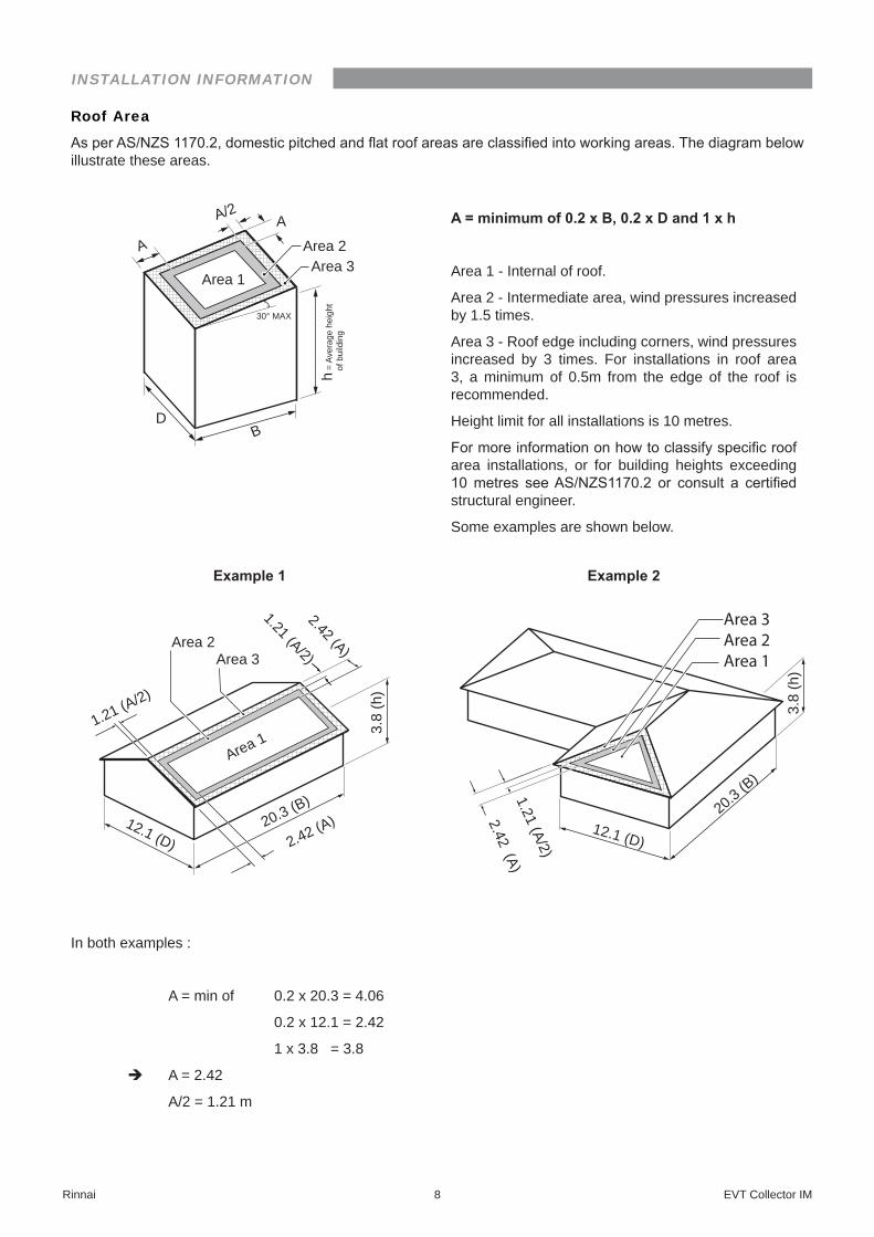
Roof Area
As per AS/NZS 1170.2, domestic pitched and flat roof areas are classified into working areas. The diagram below illustrate these areas�
Area 1
Area 2Area 3
30° MAXh
= Av
erag
e he
ight
o
f bui
ldin
g
D
A
B
AA/2 A�=�minimum�of�0.2�x�B,�0.2�x�D�and�1�x�h
Area 1 - Internal of roof�
Area 2 - Intermediate area, wind pressures increased by 1�5 times�
Area 3 - Roof edge including corners, wind pressures increased by 3 times� For installations in roof area 3, a minimum of 0�5m from the edge of the roof is recommended�
Height limit for all installations is 10 metres�
For more information on how to classify specific roof area installations, or for building heights exceeding 10 metres see AS/NZS1170.2 or consult a certified structural engineer�
Some examples are shown below�
Example�1
3.8
(h)
1.21 (A/2) 2.42 (A) Area 3
12.1 (D) 20.3 (B)
1.21 (A/2)
2.42 (A)
Area 2
Area 1
Example�2
12.1 (D)
20.3 (B)
3.8
(h)
2.42 (A) 1.21 (A/2)
Area 3Area 2Area 1
In both examples :
A = min of 0�2 x 20�3 = 4�06
0�2 x 12�1 = 2�42
1 x 3�8 = 3�8
è A = 2�42
A/2 = 1�21 m
INSTALLATION INFORMATION
INSTALLATION - EVACUATED TUBES
Rinnai 9 EVT Collector IM
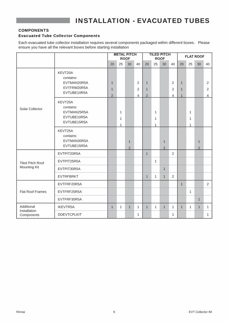
COMPONENTSEvacuated Tube Collector Components
Each evacuated tube collector installation requires several components packaged within different boxes� Please ensure you have all the relevant boxes before starting installation
METAL�PITCH�ROOF
TILED�PITCH�ROOF FLAT�ROOF
20 25 30 40 20 25 30 40 20 25 30 40
Solar Collector
KEVT20A contains: EVTMAN20R5A EVTFRM20R5A EVTUBE10R5A
1
1
2
2
2
4
1
1
2
2
2
4
1
1
1
2
2
4
KEVT25A contains: EVTMAN25R5A EVTUBE10R5A EVTUBE15R5A
1
1
1
1
1
1
1
1
1
KEVT25A contains: EVTMAN30R5A EVTUBE15R5A
1
2
1
2
1
2
Tiled Pitch Roof Mounting Kit
EVTPIT20R5A 1 2
EVTPIT25R5A 1
EVTPIT30R5A 1
EVTRFBRKT 1 1 1 2
Flat Roof Frames
EVTFRF20R5A 1 2
EVTFRF25R5A 1
EVTFRF30R5A 1
Additional Installation Components
IKEVTR5A 1 1 1 1 1 1 1 1 1 1 1 1
DDEVTCPLKIT 1 1 1

INSTALLATION - EVACUATED TUBES
Rinnai 10 EVT Collector IM
Manifold, Base Frame and Bottom Support Assembly Kit Components
EVTM
AN20R5A
EVTM
AN25R5A
EVTM
AN30R5A
EVTF
RM20R5A
Item
EVTM
AN20R5A
EVTM
AN25R5A
EVTM
AN30R5A
EVTF
RM20R5A
1 1 1 -
Manifold Header (to suit required number of tubes)
1 1 1 -
Bottom Support Assembly (Single Tube Cap 40011224)
- 2 2 21980 mm long
Base Frame Rail A-
- 2 2 2
EVT20A 1560 mm EVT25A 1950 mmEVT30A 2340 mm
Base Frame Rail B
20 25 30 -
Dust Caps 40011220
1 1 1 -
Heat Transfer Paste 40011222
6 6 6 -
M8-16 Nut and Bolt
9 9 9 -
M6-12 Nut and Bolt
Evacuated Tubes
EVTU
BE1
0R5A
EVTU
BE1
5R5A
Item
10 15
Evacuated Tube (including heat pipe)
INSTALLATION - EVACUATED TUBES
Rinnai 11 EVT Collector IM
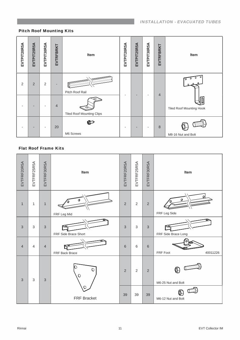
Pitch Roof Mounting Kits
EVTP
IT20R5A
EVTP
IT25R5A
EVTP
IT30R5A
EVTR
FBRKT
Item
EVTP
IT20R5A
EVTP
IT25R5A
EVTP
IT30R5A
EVTR
FBRKT
Item
2 2 2 -
Pitch Roof Rail- - - 4
Tiled Roof Mounting Hook- - - 4
Tiled Roof Mounting Clips
- - - 20
M6 Screws
- - - 8
M8-16 Nut and Bolt
Flat Roof Frame Kits
EV
TFR
F20R
5A
EV
TFR
F25R
5A
EV
TFR
F30R
5A
Item
EV
TFR
F20R
5A
EV
TFR
F25R
5A
EV
TFR
F30R
5A
Item
1 1 1
FRF Leg Mid
2 2 2
FRF Leg Side
3 3 3
FRF Side Brace Short
3 3 3
FRF Side Brace Long
4 4 4
FRF Back Brace
6 6 6
FRF Foot 40011226
3 3 3
FRF Bracket
2 2 2
M6-25 Nut and Bolt
39 39 39M6-12 Nut and Bolt
INSTALLATION - EVACUATED TUBES
Rinnai 12 EVT Collector IM
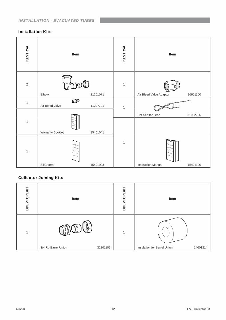
Installation KitsIKEV
TR5A
Item
IKEV
TR5A
Item
2
Elbow 21201071
1
Air Bleed Valve Adaptor 16601100
1Air Bleed Valve 11007701 1
Hot Sensor Lead 31002706
1
Warranty Booklet 15401041
1
Instruction Manual 15401100
1
STC form 15401023
Collector Joining Kits
DDEV
TCPL
KIT
Item
DDEV
TCPL
KIT
Item
1
3/4 Rp Barrel Union 32201105
1
Insulation for Barrel Union 14601214

INSTALLATION - EVACUATED TUBES
Rinnai 13 EVT Collector IM
ASSEMBLE BASE FRAME
Step 1� Place the manifold header and the bottom support assembly upside down� Place the three Base Frame Rail A as shown in the diagram�
Step 2� Fasten the rails to the header using the nuts supplied with the header�
Step 3� Fasten the rails to the bottom support assembly using the M8 nuts and bolts supplied�
Step 4� Position the two Base Frame B rails under the existing components
Step 5� Fasten using the M6 nuts and bolts supplied� Step 6� Turn assembly up correct way
INSTALLATION - EVACUATED TUBES
Rinnai 14 EVT Collector IM
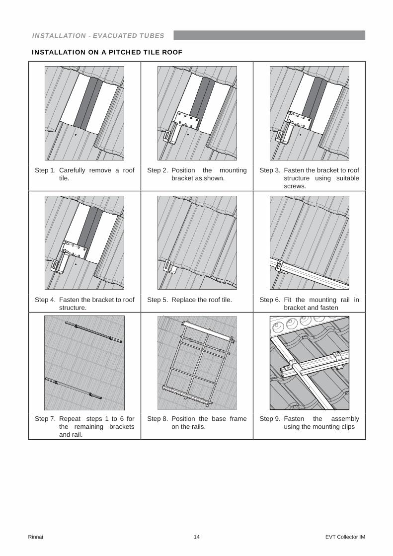
INSTALLATION ON A PITCHED TILE ROOF
Step 1� Carefully remove a roof tile�
Step 2� Position the mounting bracket as shown�
Step 3� Fasten the bracket to roof structure using suitable screws�
Step 4� Fasten the bracket to roof structure�
Step 5� Replace the roof tile� Step 6� Fit the mounting rail in bracket and fasten
Step 7� Repeat steps 1 to 6 for the remaining brackets and rail�
Step 8� Position the base frame on the rails�
Step 9� Fasten the assembly using the mounting clips
INSTALLATION - EVACUATED TUBES
Rinnai 15 EVT Collector IM
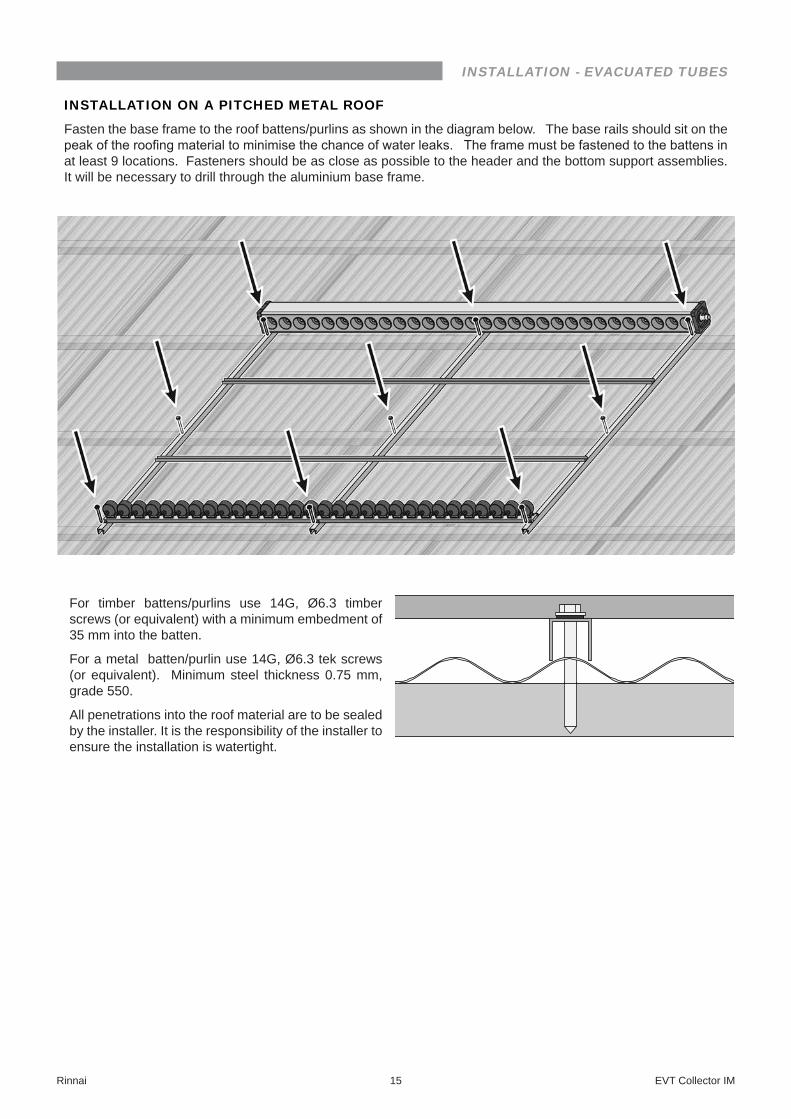
INSTALLATION ON A PITCHED METAL ROOF
Fasten the base frame to the roof battens/purlins as shown in the diagram below� The base rails should sit on the peak of the roofing material to minimise the chance of water leaks. The frame must be fastened to the battens in at least 9 locations� Fasteners should be as close as possible to the header and the bottom support assemblies� It will be necessary to drill through the aluminium base frame�
For timber battens/purlins use 14G, Ø6�3 timber screws (or equivalent) with a minimum embedment of 35 mm into the batten�
For a metal batten/purlin use 14G, Ø6�3 tek screws (or equivalent)� Minimum steel thickness 0�75 mm, grade 550�
All penetrations into the roof material are to be sealed by the installer� It is the responsibility of the installer to ensure the installation is watertight�

INSTALLATION - EVACUATED TUBES
Rinnai 16 EVT Collector IM
INSTALLATION ON A FLAT ROOF FRAME
Step 1� Turn the complete base frame upside down and connect the rear legs and brackets using the M6-12 bolts and M6 nuts as shown�
M6-25 Bolt & M6 nut
back braces flex around each other
Step 2� Connect the back braces as shown� Attach with M6-12 bolts and M6 nuts except where shown otherwise in image�
INSTALLATION - EVACUATED TUBES
Rinnai 17 EVT Collector IM
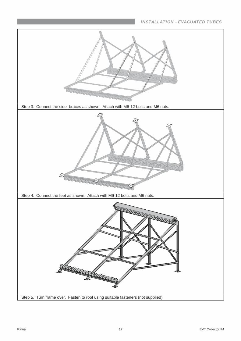
Step 3� Connect the side braces as shown� Attach with M6-12 bolts and M6 nuts�
Step 4� Connect the feet as shown� Attach with M6-12 bolts and M6 nuts�
Step 5� Turn frame over� Fasten to roof using suitable fasteners (not supplied)�
INSTALLATION - EVACUATED TUBES
Rinnai 18 EVT Collector IM
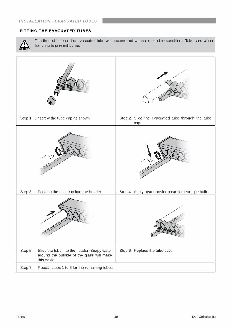
FITTING THE EVACUATED TUBES
WARNING
The fin and bulb on the evacuated tube will become hot when exposed to sunshine. Take care when handling to prevent burns�
Step 1� Unscrew the tube cap as shown Step 2� Slide the evacuated tube through the tube cap�
Step 3� Position the dust cap into the header Step 4� Apply heat transfer paste to heat pipe bulb�
Step 5� Slide the tube into the header� Soapy water around the outside of the glass will make this easier
Step 6� Replace the tube cap�
Step 7� Repeat steps 1 to 6 for the remaining tubes
INSTALLATION - EVACUATED TUBES
Rinnai 19 EVT Collector IM
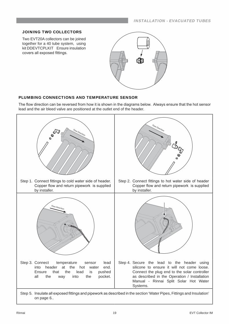
JOINING TWO COLLECTORS
Two EVT20A collectors can be joined together for a 40 tube system, using kit DDEVTCPLKIT Ensure insulation covers all exposed fittings.
PLUMBING CONNECTIONS AND TEMPERATURE SENSOR
The flow direction can be reversed from how it is shown in the diagrams below. Always ensure that the hot sensor lead and the air bleed valve are positioned at the outlet end of the header�
Flow Direction
Flow Direction
Step 1� Connect fittings to cold water side of header. Copper flow and return pipework is supplied by installer�
Step 2� Connect fittings to hot water side of header Copper flow and return pipework is supplied by installer�
Flow Direction
Step 3� Connect temperature sensor lead into header at the hot water end� Ensure that the lead is pushed all the way into the pocket�
Step 4� Secure the lead to the header using silicone to ensure it will not come loose� Connect the plug end to the solar controller as described in the Operation / Installation Manual - Rinnai Split Solar Hot Water Systems�
Step 5� Insulate all exposed fittings and pipework as described in the section ‘Water Pipes, Fittings and Insulation’ on page 6��
15401100 20 EVT Collector IM- Issue 3 - May 2016�
Head Office 100 Atlantic Drive,Keysborough, Victoria 3173
Tel: (03) 9271 6625Fax: (03) 9271 6622
P.O. Box 460Braeside, Victoria 3195
National Help LineTel: 1300 555 545* Fax: 1300 555 655*
*Cost of a local call higher from mobile or public phones.Hot Water Service LineTel: 1800 000 340
Australia Pty. Ltd. ABN 74 005 138 769 Internet: www.rinnai.com.au E-mail: [email protected]
Rinnai has a Service and Spare Parts network with personnel who are fully trained and equipped to give the best service on your Rinnai appliance. If your appliance requires service, please call our National Help Line. Rinnai recommends that this appliance be serviced every 3 years.