installation instructions for rayburn heatranger … · warranty: any alteration that is not...
TRANSCRIPT
REMEMBER, when replacing a part on this appliance, use only spare parts that you can be assured conform to the safety andperformance specification that we require. Do not use reconditioned or copy parts that have not been clearly authorised by Aga.
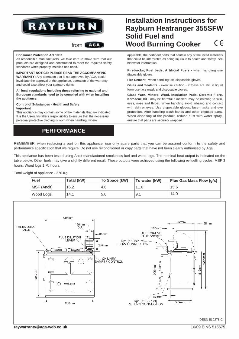
This appliance has been tested using Ancit manufactured smokeless fuel and wood logs. The nominal heat output is indicated on thetable below. Other fuels may give a slightly different result. These outputs were achieved using the following re-fuelling cycles. MSF 3hours. Wood logs 1 1/2 hours.
Total weight of appliance - 370 Kg.
Installation Instructions forRayburn Heatranger 355SFWSolid Fuel andWood Burning Cooker
PERFORMANCE
10/09 EINS 515575
DESN 510278 C
Consumer Protection Act 1987As responsible manufacturers, we take care to make sure that ourproducts are designed and constructed to meet the required safetystandards when properly installed and used.
IMPORTANT NOTICE: PLEASE READ THE ACCOMPANYINGWARRANTY: Any alteration that is not approved by AGA, couldinvalidate the approval of the appliance, operation of the warrantyand could also affect your statutory rights.
All local regulations including those referring to national andEuropean standards need to be complied with when installingthe appliance.
Control of Substances - Health and SafetyImportantThis appliance may contain some of the materials that are indicated. It is the Users/Installers responsibility to ensure that the necessary personal protective clothing is worn when handling, where
applicable, the pertinent parts that contain any of the listed materialsthat could be interpreted as being injurious to health and safety, seebelow for information.
Firebricks, Fuel beds, Artificial Fuels - when handling usedisposable gloves.
Fire Cement - when handling use disposable gloves.
Glues and Sealants - exercise caution - if these are still in liquidform use face mask and disposable gloves.
Glass Yarn, Mineral Wool, Insulation Pads, Ceramic Fibre,Kerosene Oil - may be harmful if inhaled, may be irritating to skin,eyes, nose and throat. When handling avoid inhaling and contactwith skin or eyes. Use disposable gloves, face-masks and eyeprotection. After handling wash hands and other exposed parts.When disposing of the product, reduce dust with water spray,ensure that parts are securely wrapped.
FuelMSF (Ancit)
Wood Logs
Total (kW)16.2
14.1
To Space (kW)4.6
5.0
To water (kW)11.6
9.1
Flue Gas Mass Flow (g/s)15.6
14.0

There is no requirement for an electrical power supply althougha low limit thermostat is incorporated in the boiler and if usedmust be earthed.The Rayburn 355SFW is intended to supply heating for:-
(a) Cooking and domestic hot water.(b) Cooking, domestic hot water and central heating.
WARNING: THIS APPLIANCE MUST NOT BE USEDWITHOUT WATER CONNECTED, OTHERWISE DAMAGE TOTHE BOILER MAY BE CAUSED AND/OR HEAT DAMAGETO SURROUNDING SURFACES.
Air for combustion within the firebox is obtained from twosources viz:-
a) When the appliance is being used for cooking and domestic hot water only, the rate of burning is determined by the manually operated spinwheel control on the ashpit door.
b) When central heating is also required, close the spinwheel control and operate the burning rate by means of the boiler thermostat.
The cooker has both boiler and cooker flues which areopened/closed by internal dampers working in conjunction andoperated manually by the cooker/boiler damper at the front ofthe cooker.The setting should be relative to the services required, viz:- Hfor all services, C for cooking and domestic hot water only.
When using this appliance to burn wood, all the grate platesmust be installed on the grate.
The non-combustible hearth must be solid and level andtogether with the walls adjacent to the cooker and chimney,conform to current Building Regulations.The cooker and chimney flue installation should be inaccordance with the relevant recommendations of the BritishCodes of Practice BS 8303, BS 6461 Part 1 and BS 7566 Parts1 to 4 respectively and the central heating system to BS 5449Part 1. The boiler installation section must also be inaccordance with the byelaws of the local Water Undertaking,Regulations for the Electrical Equipment of Buildings -published by the Institute of Electrical Engineers and anyrelevant requirements of the Local Authority.Ensure that any electrical wiring is correctly earthed.
When the cooker is installed in a recess it must be‘freestanding’ and not built-in solid at the sides. Ensure that anycombustible material e.g. kitchen furniture is spaced away fromthe cooker to the recommended distances. See Fig. 1.
TilingWhere the cooker is to stand in a recess or against a wall whichis to be tiled, in no circumstances should the tiles overlapthe cooker top plate.
PREPARATION OF SITE
COOKER POSITION
Fig.1
2
DESN 510279 B
WARNINGTHE ASHPIT AND FIREBOX DOORS MUST BE LOCKED
CLOSED AT ALL TIMES DURING NORMAL USE, EXCEPTWHEN LIGHTING OR RE-FUELLING.
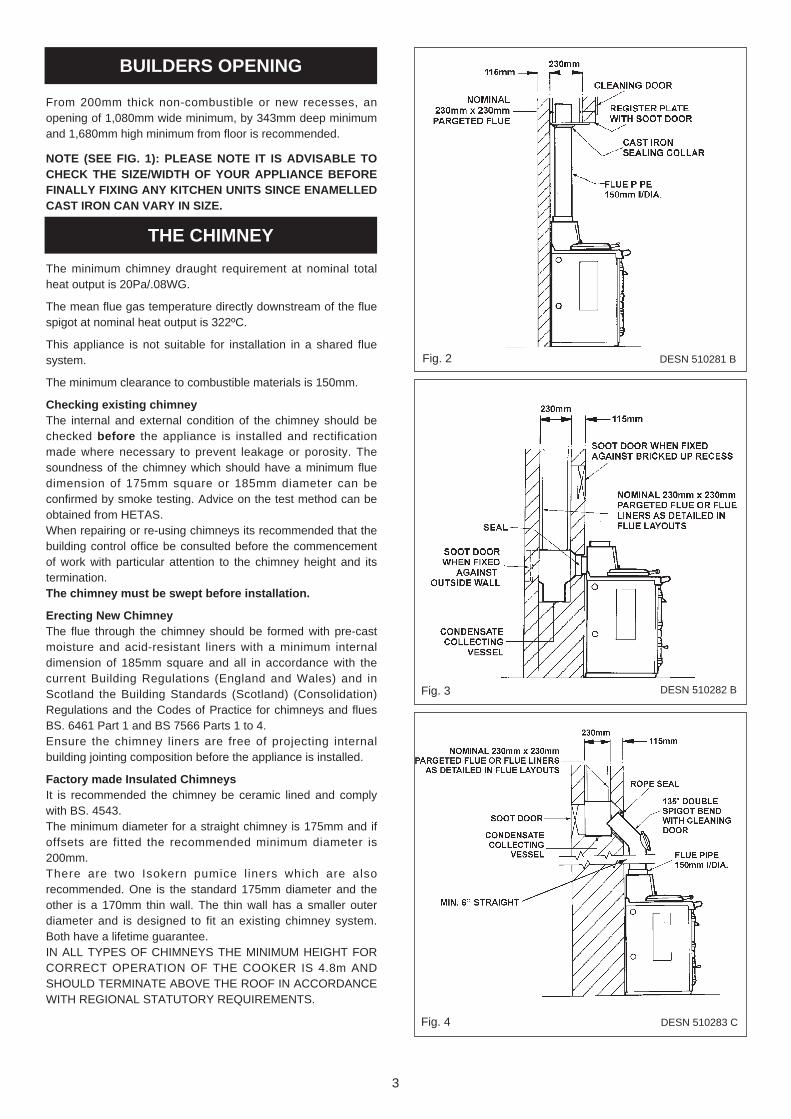
From 200mm thick non-combustible or new recesses, anopening of 1,080mm wide minimum, by 343mm deep minimumand 1,680mm high minimum from floor is recommended.
NOTE (SEE FIG. 1): PLEASE NOTE IT IS ADVISABLE TOCHECK THE SIZE/WIDTH OF YOUR APPLIANCE BEFOREFINALLY FIXING ANY KITCHEN UNITS SINCE ENAMELLEDCAST IRON CAN VARY IN SIZE.
The minimum chimney draught requirement at nominal totalheat output is 20Pa/.08WG.
The mean flue gas temperature directly downstream of the fluespigot at nominal heat output is 322ºC.
This appliance is not suitable for installation in a shared fluesystem.
The minimum clearance to combustible materials is 150mm.
Checking existing chimneyThe internal and external condition of the chimney should bechecked before the appliance is installed and rectificationmade where necessary to prevent leakage or porosity. Thesoundness of the chimney which should have a minimum fluedimension of 175mm square or 185mm diameter can beconfirmed by smoke testing. Advice on the test method can beobtained from HETAS.When repairing or re-using chimneys its recommended that thebuilding control office be consulted before the commencementof work with particular attention to the chimney height and itstermination.The chimney must be swept before installation.
Erecting New ChimneyThe flue through the chimney should be formed with pre-castmoisture and acid-resistant liners with a minimum internaldimension of 185mm square and all in accordance with thecurrent Building Regulations (England and Wales) and inScotland the Building Standards (Scotland) (Consolidation)Regulations and the Codes of Practice for chimneys and fluesBS. 6461 Part 1 and BS 7566 Parts 1 to 4.Ensure the chimney liners are free of projecting internalbuilding jointing composition before the appliance is installed.
Factory made Insulated ChimneysIt is recommended the chimney be ceramic lined and complywith BS. 4543.The minimum diameter for a straight chimney is 175mm and ifoffsets are fitted the recommended minimum diameter is200mm. There are two Isokern pumice l iners which are alsorecommended. One is the standard 175mm diameter and theother is a 170mm thin wall. The thin wall has a smaller outerdiameter and is designed to fit an existing chimney system.Both have a lifetime guarantee.IN ALL TYPES OF CHIMNEYS THE MINIMUM HEIGHT FORCORRECT OPERATION OF THE COOKER IS 4.8m ANDSHOULD TERMINATE ABOVE THE ROOF IN ACCORDANCEWITH REGIONAL STATUTORY REQUIREMENTS.
Fig. 2
Fig. 3
Fig. 4
3
THE CHIMNEY
DESN 510281 B
DESN 510282 B
DESN 510283 C
BUILDERS OPENING

RECOMMENDED FLUE DRAUGHT - 20Pa/.08WG MINIMUM.THE APPLIANCE SHOULD BE INSTALLED AND CONFORMTO THE CURRENT CODES OF PRACTICE FORINSTALLATION OF DOMESTIC HEATING AND COOKINGAPPLIANCES BURNING SOLID FUEL - BS 8303.
ALWAYS ADVISE THE USER TO CLEAN THE COOKERFLUES IN ACCORDANCE WITH THE OPERATINGINSTRUCTIONS AND TO HAVE THE CHIMNEY SWEPT AT A MINIMUM OF 12 MONTHLY INTERVALS AFTER THECOOKER IS COMMISSIONED.
WARNING: PROLONGED SOOT FORMATION MAY RESULTIN THE FLUEWAYS BECOMING BLOCKED AND COULDGIVE RISE TO THE RELEASE OF CARBON MONOXIDE, APOISONOUS GAS INTO THE ROOM.
The position of available types of flue layouts are shown inFigs. 2, 3 and 4, the cooker flue chamber is adaptable toprovide either top or back flue outlets, by means of thereversible loose socket.(a)Rear Flue Outlet
This must only be used where there is a brick flueimmediately behind the cooker. Provision must be made for a condensate collecting vessel and cleaning door. See Fig. 3.
NOTE: EXTENDED REAR FLUE PIPE AND BENDS ARE NOTRECOMMENDED.
(b)Top Flue OutletThe cooker should be connected to the main flue via a 150mm minimum diameter cast iron flue pipe or appropriately sized vitreous enamelled mild steel pipe and be sealed to the cooker flue chamber with soft rope and fire cement. A minimum 6” vertical length of flue pipe must be fitted before any bend is included.Any bends in the flue pipe must be not less than 135º (45º from horizontal) and be complete with a cleaning door.
In Fig. 2. the cooker is installed in an existing recess. Theremust be a clearance of not less than 150mm between the top ofthe flue pipe and any overhanging brickwork.Any cavities or pockets above the register plate should as faras possible be filled and if necessary the flue pipe should beextended into the throat of the chimney and soot door providedfor chimney sweeping.If a flue liner or insulated chimney is used, the size should notbe less than 185mm square or 225mm diameter, and 175mmdiameter respectively. There are two Isokern pumice l iners which are alsorecommended. One is the standard 175mm diameter and theother is a 170mm thin wall. The thin wall has a smaller outerdiameter and is designed to fit in an existing chimney system.Both have a lifetime guarantee.In Fig. 3, the cooker is connected direct to a brick flue.Horizontal pipe runs between cooker and brick flue must notbe used.In Fig. 4, the cooker is connected to an existing brick flue with alength of flue pipe. Square bends and horizontal runs must notbe used. There must be a cleaning door at every bend.NOTE: WHATEVER METHOD OF INSTALLATION ISEMPLOYED, AIR MUST NOT BE ALLOWED TO ENTER THECHIMNEY EXCEPT THROUGH THE COOKER. ALL JOINTS
MUST BE AIR-TIGHT.If the chimney is unlined, and there is any doubt about itscondition, it should be lined in accordance with current BuildingRegulations.PROVISION MUST ALWAYS BE MADE FOR SWEEPINGTHE CHIMNEY.IMPORTANT: CEMENT TYPE PIPES AND FITTINGS MUSTNOT BE USED WITHIN 2m. OF THE COOKER. CHIMNEYSOF PLAIN PIPE ARE NOT RECOMMENDED BUT CERTAINPROPRIETARY MAKES OF INSULATED CHIMNEY ARESUITABLE.
Provision must be made for a permanent unobstructed air venthaving a minimum effective area of 62cm2 (9.6 sq in)communicated directly to outside air or an adjacent room whichitself has a permanent air vent of at least this size direct tooutside air.
If a flue draught stabiliser is fitted in the flue this appliancerequires a permanent open air vent of 110 cm2.
4
FLUE LAYOUTS
Fig. 5 Typical CentralHeating/Hot Water System
Fig.6 Typical Wiring Diagram
DESN 510284’A’
DESN 510285 A
COOKER FLUE CONNECTION
AIR SUPPLY
Any air inlet grilles must be positioned so that they are notliable to blockage.
It is not permissible to use an air extraction device in the sameroom as the appliance, unless additional ventilation is providedto prevent any adverse effect on the flue.
Effect of Extractor FanAvoid if possible the installation of extractor fan in the sameroom as the cooker. Compensating extra air inlets must beintroduced equivalent to the capacity of the fan when fitted.
THIS APPLIANCE MUST NOT BE USED WITHOUT WATERCONNECTED.
It is recommended that a 190 litre (40 galls) indirect hot waterstorage cylinder of the double feed type e.g. (Manufactured byAlbion Cylinders, complying with BS. 1566 Part 1:DF Type 10)should be lagged and fixed vertically as near as possible to thecooker.The 28mm minimum diameter primary flow and return pipesmust not exceed 10m in length and pipes longer than 5m mustbe lagged.Ensure that the f low pipe has an open vent and risescontinuously from the boiler to the cylinder to ensure good gravity circulation.In combined systems, the water draw-off pipes to the taps mustbe dead-leg connection from the vent/expansion pipe.There are only two boiler tappings on this cooker and a typicaldesign layout is shown in Fig. 5.An injector tee is provided which must be fitted to ensureadequate primary flow circulation when the water circulator isoperating, otherwise there may be a lack of domestic hot water.The heating flow and return pipes may be 22mm, the returnpipe being connected to the 28mm primary return by theinjector tee, and the tee outlet connected to the boiler returnpipe.All installations must be fitted with a drain tap at the lowestpoint of the system.
Corrosion InhibitorA corrosion inhibitor MUST be added to the heating system toprotect the heat exchanger and pipework. Inhibitor must also bereplaced if the system is drained after installation. As aprecaution, the heating system MUST also be flushed out priorto the addition of the inhibitor to ensure any flux, debris isremoved.
In order to maximise the life of your boiler body, an electricalthermal re-set low temperature boiler thermostat has been fittedwithin the appliance, behind the LH side removable cover,whose purpose is to isolate the electrical power from the watercirculator when the boiler thermostat falls below 60ºC (140ºF)and thus minimise harmful condensation on the boiler surfaces.The 3 core 0.75mm2 cable lead from the appliance must beconnected to/from the water circulator as indicated on the‘Typical Wiring Diagram’ in Fig. 6. Marked ‘Boiler LowTemperature Thermostat’ - This switch is normally closedduring cooking operation and will open when the watertemperature falls, preventing chilling of the boiler.
NOTE: IF THERE IS A POSSIBILITY OF BOILING TAKINGPLACE A REVERSE ACTING THERMOSTAT SHOULD BEFITTED TO THE DOMESTIC HOT WATER CYLINDER ORBOILER PRIMARY FLOW PIPES, AND ELECTRICALLYCONNECTED TO THE CENTRAL HEATING PUMP, THISWILL SWITCH THE PUMP ‘ON’ TO PREVENT BOILING. ATLEAST ONE RADIATOR (USUALLY THE BATHROOM)SHOULD NOT BE FITTED WITH A TRV (THERMOSTATICRADIATOR VALVE), TO ACT AS A HEAT LEAK, SHOULDTHE BOILER OVERHEAT AND THE PUMP FAIL TO START.
Tall chimneys may develop excessively high updraughts whichprevent the appliance operating correctly.It is recommended that a proprietary brand adjustable fluedraught stabiliser having an openable cross sectional area of182.5sq cm (6”ø pipe) be fitted above the flue pipe connection,either in the brickwork or into a right angle ‘T’; fitting in the fluepipe position that will not inconvenience appliance operation ormaintenance.
The Rayburn 355SFW is delivered complete including a set ofboiler removable firebricks where positional location determinesthe amount of hot water supplied in winter and summerseasons.The oven side and firebox front firebricks are permanently fixedwith fire cement, whilst the two boiler face side bricks and boilerback brick are located for the summer season thereby providingdomestic hot water only. For winter use or central heatingfacilities, the boiler face rear brick is removed and the boilerface side bricks are transferred to locate on/over the oven sidefirebricks. See diagram 7 & 7A.The firebricks fitted to the Rayburn Cookers are of first qualitymanufacture, and providing the cooker has been installed andused correctly will have a reasonable life. These are, however,expendable items and in time will require renewal. The renewalof firebricks is not a major operation and can be carried out bythe average handyman. Replacement bricks either in sets orsingly can be obtained from your Rayburn Distributor. Quotethe serial number which will be found on the appliance dataplate.
5
HIGH UPDRAUGHTS
BOILER - Control
CENTRAL HEATING ANDHOT WATER SYSTEM
GENERAL - Firebrick Positionsand Replacement

WINTER USE (DOMESTIC HOT WATER & CENTRALHEATING) SIDE FIREBRICKS ‘A’ MOUNTED IN RIGHTHAND SIDE OF FIREBOX OVER PERMANENTLY FIXEDOVEN SIDE FIREBRICKS & REAR FIREBRICK ‘B’REMOVED.
SUMMER USE (DOMESTIC HOT WATER ONLY) SIDEFIREBRICKS ‘A’ MOUNTED IN LEFT HAND SIDE OFFIREBOX & REAR FIREBRICK ‘B’ IN POSITION.
Note (Fig. 8) - Position of grate baffle for woodburning only. Ensure the 3 grate baffles are in placebefore firing.
To be fitted before placing baffles and firebricks inposition.Fig. 7A DESN 510287
6
DESN 515159 AFig. 8
Fig. 9A Flue Restrictor Plate - Wood Burning
Fig. 7 DESN 510286
Fig. 9 Both Flue Restrictor Plates
Fig. 9A Flue Restrictor Plate - Mineral Fuels

Place the cooker in the intended position and out lift the surfaceground hotplate, checking that the joint between the undersideof the hob and the top of the cooker is intact.Any joints which have opened should be made good with firecement provided.
If the appliance is installed near combustible material then aswell as adhering to minimum clearances in Fig. 1 additionalnon-combustible insulation must be fitted to the wall to protectthe area around the flue and fluebox. The insulation must reacha minimum distance of 150mm either side of the flue/flue boxand follow the line of the flue. The minimum specification for
this material is Superwool 607 LTI with a density of 320kg/m3,a thickness of 10mm and a self finish. There must be aminimum 16mm air gap between the insulation board and anadjacent combustible wall surface. A higher specificationmaterial may be used but the air gap must be maintained.
Check that the boiler/cooker flueway dampers operate correctlyby turning the knob on the front plate adjacent to the top lefthand corner of the roasting oven door.
NOTE: IT IS NOT VISUALLY POSSIBLE TO SEE THEBOILER DAMPER AND THIS SHOULD BE CHECKED BYFEELING THROUGH THE HOTPLATE APERTURE TO THEBACK OF THE COOKER. THE COOKER DAMPER SPINDLEOPERATES THE BOILER DAMPER WHICH CAN BE FELTBY INSERTING HAND INTO FLUEWAY.
Replace the hotplate making sure that it is seating evenly onthe soft rope and that it is approximately 1.5mm proud of theenamelled top plate, with an equal space all round.1. Connect pipework to boiler flow and return tappings.2. Fit the flue chamber which should have a rope seal already
installed. The flue chamber is screwed to the cooker making a good seal as any air leak at this point will impede the working of the cooker.
3. Open the firebox and ashpit doors and check that the reciprocating bottomgrate bars are in position. Operate the riddling lever to ensure bottomgrate operation.When the 3 grate plates are in place the riddling lever will not operate fully, as these plates, if fitted correctly will lock the reciprocating bars.Make sure that the restrictor plate is installed at the rear of the firebox covering the flueway (flat plate for solid mineral fuels).
4. Turn the boiler thermostat knob at the rear left hand corner of the top plate from No.1 (low) to No.8 (high).
NOTE: THE HIGHER THE NUMBER, THE HIGHER THEWATER TEMPERATURE.
The handrail brackets are held on the front ends of the cookertop-plate casting. Remove the travel nuts and replace with thehandrail brackets ensuring the fibre protecting washers are inposition. Insert the handrails with fitted endcaps into thebrackets, positioning them correctly, and tighten the locatingbolts (Fig. 9).
After completing the installation the heating contractor shoulddemonstrate to the user, the operation of the appliance androutine cleaning method.
The protective grease should be removed from the hotplatebefore lighting.
When lighting, check that the cooker flueway is set to ‘C’cooker, the fluebox damper is fully out and the chamber door isclosed. The thermostat should be at 8, maximum and thespinwheel open. The secondary air slide inside the firebox doorshould be set open. These settings will allow maximum draughtfor the firebox and flue. The cooker must not be left in thiscondit ion, as the open spinwheel is not controlledthermostatically.
The firebox door and the ashpit door are interlocked so the topdoor has to be opened before the bottom. Add paper andkindling to the grate and light. Close both doors. After a fewminutes the fire should pick up, gradually add larger pieces offuel. Allow the cooker to establish the fire and gradually reducethe amount of air going into the firebox. Start closing down thespinwheel so that the cooker is working on the thermostat. Itmay be that in normal running the spinwheel needs to beslightly open depending upon the heat requirements.
For the first couple of days do not overfire. The cast iron insidethe cooker will build up heat gradually and overfiring may causedamage.
NOTE: SMOKE/SMELL EMITTED DURING INITIAL USAGE
Some parts of the cooker have been coated with a lightcovering of protective oil. During initial operation of the cooker,this may cause smoke/smell to be emitted and is normal andnot a fault with the appliance, it is therefore advisable to opendoors and or windows to allow for ventilation. Lift the lids toprevent staining the linings.
7
TESTING AND COMMISSIONING
INSTALLATION
DESN 510454 AFig. 9
8
For further advice or information contact yourlocal distributor/stockist
With AGA’s policy of continuous productimprovement, the Company reserves the right tochange specifications and make modifications to
the appliance described at any time.
Manufactured byAGA
Station RoadKetley Telford
Shropshire TF1 5AQEngland
www.rayburn-web.co.ukwww.agacookshop.co.uk
www.agalinks.com

Consumer Protection Act 1987As responsible manufacturers, we take care to make sure that ourproducts are designed and constructed to meet the required safetystandards when properly installed and used.
IMPORTANT NOTICE: PLEASE READ THE ACCOMPANYINGWARRANTY: Any alteration that is not approved by AGA, couldinvalidate the approval of the appliance, operation of the warrantyand could also affect your statutory rights. Use only authorisedreplacement parts.
All local regulations including those referring to national andEuropean standards need to be complied with when installingthe appliance.
Control of Substances - Health and SafetyImportantThis appliance may contain some of the materials that are indicated.It is the Users/Installers responsibility to ensure that the necessary
personal protective clothing is worn when handling, whereapplicable, the pertinent parts that contain any of the listed materialsthat could be interpreted as being injurious to health and safety, seebelow for information.
Firebricks, Fuel beds, Artificial Fuels - when handling usedisposable gloves.
Fire Cement - when handling use disposable gloves.
Glues and Sealants - exercise caution - if these are still in liquidform use face mask and disposable gloves.
Glass Yarn, Mineral Wool, Insulation Pads, Ceramic Fibre,Kerosene Oil - may be harmful if inhaled, may be irritating to skin,eyes, nose and throat. When handling avoid inhaling and contactwith skin or eyes. Use disposable gloves, face-masks and eyeprotection. After handling wash hands and other exposed parts.When disposing of the product, reduce dust with water spray,ensure that parts are securely wrapped.
The Rayburn 355SFW has been designed to burn avariety of solid fuels and thereby provide heating facilitiesfor cooking, domestic hot water and central heating.The thermostatically controlled hot water boiler can beoperated independently of the cooker and will provide hotwater for central heating and domestic use, whilstmanually operated spinwheel control on the front of theashpit door will provide heat for cooking and domestichot water.The cooker/boiler flueway damper knob on the centrefront of the cooker below the top plate requires to be setin conjunction with the flue chamber damper to obtain theappropriate service required from the appliance.
FIREBRICK POSITIONSThe Rayburn 355SFW is delivered complete including aset of boiler removable firebricks where positionallocation determines the amount of hot water supplied inwinter and summer seasons.The oven side and firebox front f irebricks arepermanently fixed with fire cement and should remain intheir positions at all times.The two boiler face side bricks and boiler face rear brickare so located for summer use when hot water, fordomestic use only, will be provided.For winter use or central heating facilities the boiler facerear brick is removed and the two boiler face side bricksare transferred to locate on/over the oven side bricks.The removable firebricks can be fitted or not at thediscretion of the user in the position that gives the most benefit. Generally the firebrick will change the distributionof the heat, so placing it on the oven side will reduce heat
to the oven and increase heat to water. Placing it on oneor more boiler side will reduce the heat to water. Thefirebricks can be used in separate sections as requiredand do not have to be fully fitted or removed.
Secondary Air Slide.On opening the firedoor the secondary air slide is seenon the base of the opening and should be set according to the fuel being used as follows:-Air Slide Open - wood logsAir Slide Closed - manufactured smokeless fuels
Users Instructions.Rayburn Heatranger 355SFWSolid Fuel andWood Burning Cooker
INTRODUCTION
PREPARING COOKER FOR USE
1 10/09 EOPI 515579
WARNINGTHE ASHPIT AND FIREBOX DOORS MUST BE LOCKED
CLOSED AT ALL TIMES DURING NORMAL USE, EXCEPTWHEN LIGHTING OR RE-FUELLING.
Fig. 1

FLUE RESTRICTOR PLATEThere are two plates supplied. The flat plate with holes isfor burning solid mineral fuels and the similar plate with ascoop is for wood logs only. This plate is fitted at the rearof the firebox covering the flueway opening and is to beused when burning a specified fuel only. Do not usethe plate with the scoop when burning solid mineralfuels. This part can only fit one way round. Whenburning wood, fit this part before the grate plates andfirebricks.
GRATE PLATESThree plates are supplied with the cooker and are fittedover the grate bars when burning wood only. Do notuse these when burning solid mineral fuels. Fit theplates, with the return edge downwards, evenly front torear. The grate plate will have the effect of locking theriddling mechanism so when burning wood riddling is notnecessary. Position the riddling handle centrally in its slotto align the grate bars before fitting.
This appliance has been tested using manufacturedbriquetted smokeless fuel (Taybrite and Ancit) for closedappliances sized between 20g and 140g. Other fuels arecommercially available and may give similar results.
WARNING: HOT SURFACES, use the tool supplied tooperate this appliance. It is recommended to use theheatproof glove supplied when raising the dome lids touse the hotplate. Replacement gloves can be obtainedfrom the Aga Shop.
Fig. 2
Fig. 3 Both Flue Restrictor Plates
Fig. 4 Wood Setup
Fig. 5 Solid Mineral Fuel Set-up
2

MANUFACTURED - SUNBRITE SINGLES, SUNBRITEDOUBLES, COALITE, PHURNACITE and SUPACITE.NATURAL - ANTHRACITE LARGE & SMALL NUTS,SELECTED HOUSECOAL (TREBLES/LARGE NUTSAND DOUBLES/NUTS), TAYBRITE, COKE, WOODLOGS
PETROLEUM COKE MUST NOT BE USED.
Oversize fuel lumps should be broken down to size.Stones and other foreign bodies should be removedwhen fuelling.
Fuel should be stored under cover and ventilated,particularly manufactured fuels which must be kept dry.Wet kitchen refuse should not be burned.
Any air inlet grilles must be maintained so that they arefree from blockage.
Failing to maintain your cooker properly can lead to achimney fire. Chimney fires occur when combustibledeposits on the inner walls of the chimney ignite. Thesecombustible deposits, called “creosote”, are a natural by-product of wood burning. A fire hazard exists if 1/4” ofcreosote (or more) coats the inner walls of the chimney.
OVEN DOOR OPERATION - SEE FIG. 6
To open the doors. Twist the handle slightly to lift up thedoor catch from the locking spindle and pull the dooropen.
To close the doors. Gently push the door shut until thedoor catch makes contact with the locking spindle.
FIREDOOR/ASHPIT DOOR OPERATIONThe firedoor and ashpit door are kept closed by a turnscrew. A tool is supplied to operate these when hot andthey can be adjusted to ensure both these doors closetightly. IT IS IMPORTANT TO ENSURE PROPERCLOSURE OF THESE DOORS TO PREVENTOVERFIRING.
DOOR OPERATION
DESN 512979
DESN 514177
3
Fig. 6
Fig. 7
RECOMMENDED SOLID FUELS

The cooker will satisfactorily burn wood logs, blocks orpeat briquettes, but logs should be perfectly dry in orderto obtain the best cooker performance and minimise thedeposits of creosote. Wood logs may also provideovernight banking problems and the following hints arerecommended:-a) Burn dry soft wood in the day time and dry hard
wood overnight if possible.b) Avoid using ‘green’ wood on overnight banking as
creosote deposits will be increased.c) Using hard wood in the day time will give prolonged
burning but heating response is slower.d) Wet kitchen refuse should not be burned.e) Before refuelling, open the flue chamber damper to its
full extent and fill the firebox up to the bottom of the firedoor opening, ensuring the secondary air is at fullyopen.
f) To obtain the optimum burning rate when burning wood logs the grate plates should be fitted to the top of the fire bars in the firebox. Riddling is not required when burning wood, poking will normally suffice. Takecare not to upset the plates when using the poker. These plates must be removed when burning solid mineral fuels.
All Fuels using Wood and Papera) Check the flue pipe is free of blockage.b) Open firebox door.c) Open ashpit door.d) De-ash (Fig. 12) and remove dead fuel from
bottomgrate (lift off clinker door above the bottomgrate (Fig. 14), rake fuel into ashpan replace clinker door).
e) Remove ashpan, empty and replace (Fig. 13).f) Open flue chamber damper to maximum (Fig. 11).g) Flue dilution lever fully to ‘left’ (flue chamber door
closed, Fig. 11).h) Lay a liberal supply of wood and paper on top of the
bottomgrate bars together with a small quantity of fuel and light.
i) Close and lock the ashpit door with the spinwheel control open.
j) Close and lock the firedoor.k) With fire established, open firebox door and fill firebox
with fuel. Check secondary air slide setting (Fig. 10). Close and lock firebox door. Push flue chamber damper back to position which has been found to givedesired burning rate.
All fuels Using a Gas Pokera) Check flue pipe is free of blockage.b) Open firebox door.c) Open ashpit door.d) De-ash (Fig. 12) and remove clinker door (Fig. 14).
Insert flat bayonet type gas poker on top of bottomgrate bars.
e) Remove ashpan and empty (Fig. 13).f) Open flue chamber damper to maximum (Fig. 11).g) Flue dilution lever fully to ‘left’ (flue chamber door
closed, Fig. 11).h) Lay a 75-100mm 3”-4”) shallow depth of fuel onto the
bottomgrate and light gas poker.i) Close the ashpit and firebox doors as far as possible-
spinwheel control open.j) When the fuel is well alight, extinguish and remove
the gas poker, replace the clinker door and ashpan, close and lock the ashpit door with the spinwheel control open. close the firedoor.
k) With the fire established open the firebox door and fill firebox with fuel. Check secondary air slide setting (Fig. 6). Close and lock the firebox door.Push the flue chamber damper back to position whichhas been found to give best results. Set spinwheel control to give desired burning rate.
Cooking Only - All Fuelsa) The fire is controlled by using the spinwheel on the
ashpit door to govern the air supply.b) The adjustable flue chamber damper is for reducing
the chimney draught, and the more it can be closed, the easier the cooker is to control. The line markings on the flue chamber enable you to repeat the best settings to suit your chimney, from No.1 in a closed position to No.6 fully open. Try a mid-way point first.
c) Control over the direction of the flue gases is obtained by the setting of the cooker/boiler damper.
FUELLING WITH WOOD OR PEAT
FAMILIARISE YOURSELF WITH THECOOKER
LIGHTING THE FIRE
4
COOKER CONTROL
Fig. 8
Fig. 9

Set the cooker/boiler damper knob on the front of the cooker to ‘C’ and the boiler thermostat knob on the rear left hand corner of the top plate to No. 2 or No. 3.If more heat is required set to a higher number.
NOTE: INTERMEDIATE SELECTIVE SETTINGS OFTHE COOKER/BOILER DAMPER KNOB AWAY FROM‘C’ WILL PROGRESSIVELY RESTRICT THE AMOUNTOF HEAT TO THE TOP OF THE OVEN ANDINCREASE THE AMOUNT OF HEAT INTO THEBOILER UNTIL THE KNOB IS POINTING TO SYMBOL‘H’ FOR MAXIMUM WATER HEATING. IN THISPOSITION, THE MINIMUM PROPORTION OF HEAT ISDIRECTED TO OVEN HEATING. ALTHOUGH THEOVEN WILL STILL GET HOT.
Cooking Only - All FuelsSet the spinwheel open. The precise amount will beshown by experience with the appliance.After setting the cooker/boiler damper knob to ‘C’, set theflue chamber damper fully open after refuelling and resetto position which has been found by practical experienceto give the best results. Do not try to obtain a fastincrease in temperature by opening flue chamber to itsfullest extent. This results in most of the heat beingwasted up the chimney.Avoid excessive fire temperatures with solid fuel - theyare unnecessary and may do serious harm to the cooker.The first symptoms of an overheated cooker is theformation of clinker (melted ash) which will damage thefire bricks.Damaged firebricks should be replaced as soon aspossible but may be temporarily repaired with firecement.Keep the ashpit door securely closed with the frontplate catch.
Solid fuelThe appliance is designed for continuous burning and thebest results will only be obtained if it is allowed to burnovernight. It is no more expensive in fuel costs.Last thing at night, de-ash the fire, empty the ashpan andfully refuel but do not overload.Ensure that the firebox and ashpit doors are securelyclosed, and after closing the spinwheel, re-open it aquarter of a turn.Set the boiler thermostat knob to its minimum setting andclose the flue chamber damper plate to No. 1 setting. Setthe cooker/boiler chamber knob to ‘C’ to obtain optimumheat into oven and hot plate.NOTE: THE BEST POSITION FOR THE FLUECHAMBER DAMPER CAN BE FOUND ONLY BYEXPERIMENT BUT ALWAYS TRY THE LOW SETTINGFIRST.In the morning, open the spinwheel three complete turns,
CONTROL SETTING
Fig. 10
Fig. 11
Fig. 12
Fig. 13
Fig. 14
OVERNIGHT BANKING
5

open the flue chamber damper to maximum and riddlethe fire. When it is burning brightly, close the fluechamber damper, but do not refuel before use if thehotplate is required immediately, unless there is a risk ofthe fire going out.
All Fuels.Set the cooker/boiler damper knob ‘H’.Close spinwheel.To regulate burning, set the boiler thermostat knob to ‘8’(high) or minimum rate ‘1’ (low).Adjust as required to suit desired water heating.Overnight banking and daytime slow burning should beobtained with the boiler thermostat knob set at ‘1’ to giveextended burning.Wood burningSome woods are more difficult to burn therefore it maybe necessary to open the spinwheel in addition to thethermostat to obtain the desired results. The spinwheelmust be closed as appropriate. Do not leave the cookerfor extended periods with the spinwheel open as thecooker may overheat and cause damage.In some circumstances it may be possible to overheatthe appliance and the water inside will boil. This will beevident by the sound of a knocking noise coming fromthe appliance and pipes around the house. If this occursclose off all air controls and manually start the centralheating pump if fitted. Opening the oven doors andhotplate covers will help to release heat from theappliance. Be aware that steam and boiling water will beexpended from any open vent from the heating systemprobably in the roof space at the expansion tank.In the unlikely event that the appliance is not operating infreezing conditions the water must be drained from theboiler to prevent frost damage.
Solid FuelThe appliance may be operated overnight for thepurpose of selected central heating when inclementweather conditions occur.Set the cooker/boiler damper knob to ‘H’ after refuellingetc. and the boiler thermostat knob to No. 2 with the fluechamber damper set at minimum. The spinwheel shouldbe closed and about four radiators can be run overnightunder these conditions.NOTE: THE HOTPLATE AND OVEN TEMPERATUREWILL BE CONSIDERABLY LOWER AND EXTENDEDTIME WILL BE NEEDED TO HEAT UP THESEFEATURES. DO NOT FORGET TO RE-SET THECOOKER/BOILER KNOB TO ‘C’ FOR COOKINGAFTER OVERNIGHT USE.
WoodThe appliance is designed for continuous slumberingovernight for up to a maximum of 10 hours depending onthe type of dry wood being used. Last thing at night, openthe flue chamber damper. de-ash the fire, empty theashpan and fully refuel.
Ensure that the firebox and ashpit door are securelyclosed, close the spinwheel tight and the flue chamberdamper is set to No.1.Set the boiler thermostat knob to its minimum settingand the front damper knob to ‘c’.Turn the flue dilution lever (See Fig. 11) from left to righthand so that the flue chamber door opens at the bottomand minimise burning rates.NOTE: THE PRECISE AMOUNT OF OPENINGDEPENDS ON THE CHIMNEY DRAUGHT, THETYPE/CONDITION OF WOOD TO BE BURNT ANDTHIS MAY TAKE 2 OR 3 DAYS TO ASCERTAIN.1. If the fuel in the firebox is exhausted prematurely, the
overnight chimney draught must be reduced by increasing the opening setting of the flue chamber door, using the flue dilution lever.
2. If the fuel does not burn but ‘dies out, the draught should be increased by reducing the opening setting.of the flue chamber door, using the flue dilution lever.It maybe necessary to set the thermostat to a higher number to allow more air.
Following overnight banking, the flue chamber door mustbe closed, the spinwheel and flue chamber damperopened and the fire refuelled.Immediately the new fuel has caught alight, close the fluechamber damper.NOTE: BUILD-UP OF CREOSOTE DEPOSITS IN THEFLUE AND CHIMNEY CAN IN TIME, LEAD TOCHIMNEY FIRE.THESE DEPOSITS CAN BE PREVENTED BY THEREGULAR USE OF A PROPRIETARY BRAND OFCHIMNEY CLEANER, WHICH REUDCES THESTRENGTH OF THE CREOSOTE DEPOSITS.
IMPORTANT: CHEMICAL CLEANERS MUST NOT BECONSIDERED AS AN ALTERNATIVE TO CHIMNEYSWEEPING, ONLY AS SUPPLEMENTARY.
Against Thermostat knob settings with Cooker/BoilerDamper at ‘H’ and Spinwheel closed.Thermostat Setting No. Water Temperature
(APPROXIMATE)1 46ºC (115ºF)3 54.5ºC (130ºF)5 65.5ºC (150ºF)8 80ºC (176ºF)
a) Using the cooker boiler to provide heat for domestichot water and radiators in the winter, a boiler thermostatsetting at No.8 is recommended.b) Using the cooker boiler for the provision of domestichot water only, in the summer, a boiler thermostat settingof No. 5 is recommended.NOTE: TO CONSERVE FUEL, ENSURE THE HOTWATER CYLINDER AND PIPES ARE LAGGED WITHINSULATION.
BOILER CENTRAL HEATINGTHERMOSTAT SETTING
OVERNIGHT CENTRAL HEATINGTYPICAL WATER TEMPERATURES
6
OVERNIGHT BANKING

The firebox should be filled to the recommended level ofthe bottom firebox door opening and the firebox doorclosed.A correctly fuelled fire will last a minimum of 3 hourswhen burning solid fuel and 1 1/2 hours burning woodwhen maintaining the maximum rated output of the boilerwith intermittent cooking periods included.NOTE: When burning any wood fuels and SunbriteCoke, the secondary air slide should be set in a fullyopen position.A deep bed of newly charged fuel on a low fire willtake time before heat reaches the ovens, hotplateand boiler. When burning Coal, Phurnacite andAnthracite, allow several minutes for the new chargeto ignite before changing the flue chamber dampersetting.ONCE REFUELLING HAS BEEN COMPLETED,CLOSE THE FIREBOX DOOR IMMEDIATELY ANDOPEN ONLY FOR REFUELLING CHARGES.
When burning wood, de-ashing and riddling is requiredless frequently. Usually once or twice a day is sufficienteven when in continuous use. Always de-ash beforerefuelling when burning solid mineral fuels. In winter, thismay be as much as three times daily depending uponweather severity and cooker usage.To de-ash, riddle the grate by agitating the riddlinghandle in an up and down manner 10-20 times to free thegrate of ash. See Fig. 12.ALWAYS DE-ASH BEFORE REFUELLING (SEE‘EXCEPTIONS’ BELOW) AT THE FOLLOWINGINTERVALS:-SUMMER USE:Two times daily at least.WINTER USE:Three times daily at least and more often if required.NOTE: SHOULD THE BOTTOMGRATE DE-ASHINGFAIL TO CLEAR AN ACCUMULATION OF STONES,SHALE OR CLINKER, IT MAY BE REMOVED ASDESCRIBED IN SECTION ON REMOVAL OFCLINKER.Open the ashpit door to give access to the ashpan whichmust be emptied regularly (See Fig. 13).NOTE: DO NOT ALLOW ASH TO ACCUMULATE INTHE ASHPAN UNTIL IT TOUCHES THE UNDERSIDEOF THE BOTTOMGRATE BARS OR THEY WILLQUICKLY BURN OUT.Ensure the ashpan is fully home otherwise the ashpitdoor may not close and lock completely.EXCEPTIONS:WHEN BURNING ANTHRACITE OR PHURNACITE,ALWAYS REFUEL BEFORE EMPTYING ASHPAN ANDRIDDLING.
Due to an accumulation of pieces of stone, clinker andshale etc. it may not be possible to pass them throughthe grate when riddling, and may even cause jamming.Allow the fire to burn out and then open the ashpit door.
Lift off the clinker door (See Fig. 10) and insert a hookedpoker to draw out any offending accumulation. Replaceclinker door after use.The amount of clinker formation is dependent on theheating load or burning rate and should be checkedweekly for any build-up. Excessive build-up will lead to afall in heating output requiring bottomgrate clean-out andreduction in life of the bottomgrate.
The best results can be obtained by using machinedbase utensils. The hottest part of the hot plate isimmediately above the fire, the other end being forsimmering.The circular plug in the hotplate (near the flue chamberend) is for flue cleaning and must not be removed forcooking.Keep the hotplate clean with a wire brush.NOTE: TO OBTAIN OPTIMUM HOTPLATEPERFORMANCE FOR FAST BOILING OR HOT PLATECOOKING, FUEL THE FIREBOX TO THE BOTTOMEDGE OF THE FIREBOX APERTURE TO AHORIZONTAL LEVEL.WARNING: THE COOKER TOP PLATE SURFACEAROUND THE HOTPLATE WILL BECOME HOTUNDER USE AND CARE MUST BE OBSERVED.PLEASE REFER TO THE INSTALLATIONINSTRUCTIONS REGARDING MINIMUMCLEARANCES TO COMBUSTIBLE SURFACES ANDMATERIALS.
The correct adjustment of the spinwheel and fluechamber damper to obtain the oven temperature requiredvaries with the chimney draught, and can be found onlyby experiment. The following is a suggested methodonly, and may need modification to suit local conditions.Suppose an oven temperature for roasting is desired,and that the cooker is idling.Thoroughly de-ash the fire as described in the respectiveparagraph, and refuel. Set the flue chamber damper toNo.3 setting and open the spinwheel as described under‘CONTROL SETTING’.As soon as the fire has become red all through, close theflue chamber damper. Do not allow the fire to becomewhite hot.The temperature of the oven should now rise steadily.When it reaches a point about 30ºC (50ºF) below thatrequired, close the spinwheel to approximately one turnopen. Thereafter control the temperature of the oven byadjusting the spinwheel.NOTE: THE METHOD SHOULD PROVE SUCCESSFULIN ALMOST ALL CASES, BUT IF CLOSING THE FLUECHAMBER DAMPER CAUSES THE FIRE TO SMOKE,IT SHOULD BE OPENED GRADUALLY UNTIL THESMOKING STOPS.To reduce top heat in the oven adjust the cooker/boilerdamper knob gradually away from symbol ‘C’. The ovenmay be cleaned with a stiff wire brush, when it is veryhot.
DE-ASHING
USE OF THE TOP ROASTING OVEN
REMOVAL OF CLINKER FROMBOTTOMGRATE
USE OF THE HOT PLATE
7
REFUELLING

OVEN TEMPERATURES:-HOT220º-260ºC (400º-500ºF)MODERATE150º-200ºC (300º-400ºF)SLOW90º-150ºC (200º-300ºF)
It is not possible to control this oven, but during thecourse of roasting, suff icient heat input permitssimmering of dishes that have been taken from theroasting oven.OVEN TEMPERATURES:-Idling 95ºC min.During cooking - 135ºC max.During the cooker idling periods, the oven is ideal forheating plates and keeping food warm.
WARNING: HOT SURFACES, use the tool supplied tooperate this appliance. It is recommended to use theheatproof glove supplied when raising the dome lids touse the hotplate. Replacement gloves can be obtainedfrom the Aga Shop.Following a prolonged shutdown of the appliance,perhaps after the summer break, ensure the flueway isfree from obstruction prior to re-lighting.When burning coke, anthracite, other smokeless fuels,logs or peat, the appliance flueways should be cleanedon a regular four weekly basis.When burning bituminous coal, cleaning should be doneat weekly intervals.Prolonged soot formation may result in f luewaysbecoming blocked and could give rise to the release ofcarbon monoxide, a poisonous gas into the room.Failure to ensure clean flueways, flue pipes and bendsmay lead to emission of dangerous gases and an inferiorperformance from your appliance.Cooker Flueway - Allow the fire to burn out, open theflue chamber damper to its maximum and remove theflue chamber door.Turn the cooker/boiler knob to ‘C’.Brush the soot or fly ash from the flue pipe allowing it tofall onto the top of the oven. Fig. 15.Remove the hotplate plug and rake the deposits forward,pushing them into the firebox. Figs. 16 & 17.Boiler Flueway - Set the cooker/boiler damper knob to‘H’ and remove boiler cleaning cover in top plate adjacentto boiler thermostat control knob.Lift out exposed boiler cleaning plate and brush nearboiler flueways up and down allowing debris to fall intothe firebox. Fig. 18.The flue restrictor plate may need to be removed toenable deposits to be swept out of the bottom of theboiler flueway. If necessary remove side bricks and gratebaffles to ease access.Clean boiler flue outlet by inserting brush horizontal atright hand of boiler aperture below top plate.
FLUEWAY CLEANING
8
Fig.15
Fig.16
Fig.17
USE OF THE BOTTOM COOKING OVEN
Fig.18
Check with pointerreading on ovendoor thermometer.

Push brush above and below the boiler damper so thatflash etc. is pushed onto oven top. Insert rake throughhotplate plug aperture and pull deposits into firebox (afterresetting cooker/boiler damper knob to ‘C’).Replace flue chamber door and hotplate plug and riddlethe bottomgrate thoroughly to clear the bottomgrateready for relighting.NOTE: THE APPLIANCE IS DESIGNED ANDINTENDED TO BE UNDER CONTINUOUS FIRING BUTIF IT IS NOT IN USE ASHPIT AND FLUE CHAMBERDOORS SHOULD BE LEFT OPEN TO ENSURE FREEPASSAGE OF AIR THROUGH THE APPLIANCE ANDAVOID CONDENSATION PROBLEMS.
Sweep annually and inspect soot box at 3 monthlyintervals and remove any deposits.NOTE: SWEEPS BRUSHES MUST BE OF THE TYPEWITH WIRE CENTRES AND GUIDE WHEELS.
Prevention: Chimney fires do not occur in clean, intact,properly installed chimneys. Have a professionalchimney sweep clean and inspect your appliance at leastonce a year. More frequent cleanings may be required,based on the type of fuel burned, the type of appliance,and the frequency of use. In general, an older applianceor one that is used frequently, will require more than oneclean per year.
Detection: The first indication of a chimney fire is usuallythe noise - a roaring sound grows louder as the fire’sintensity increases. Clouds of black smoke and sparkswill be seen exiting the top of the chimney; in severefires, flames can extend several feet about the chimney.
Action: In case of a chimney fire follow these steps butdo not put yourself or others in peril:
1. Call the fire brigade immediately.2. Get everyone out of the property.3. Close down the air supply to the appliance i.e. the
primary air spinner and the flue damper. Limiting the fires air supply will reduce its intensity. If there is a damper in the chimney connector, plug or close the opening.
4. If a fire extinguisher is available, open the appliance door just enough to insert the nozzle of a 10lb, dry chemical fire extinguisher rated for Class ABC fires. Discharge the entire content of the fire extinguisher into the appliance and shut the door.
5. If possible, wet down the roof and other outside combustibles to prevent fires ignited by shooting sparks and flames.
6. Closely monitor all combustible surfaces near the chimney. During severe chimney fires, these surfacescan become hot enough to ignite.
After a chimney fire, have the chimney inspected by aprofessional chimney sweep or cooker installer.
Surface blemishes caused by spillage on the glossenamel are easier to remove when the cooker is cool,and a damp cloth is usually all that is necessary.This should not be done whilst the cooker is hot.DO NOT USE ABRASIVE PADS, OVEN CLEANER, ORCLEANERS CONTAINING CITRIC ACID ONENAMELLED SURFACES.
IMPORTANT NOTE: Aga recommend Vitreous EnamelAssociation approved cleaners for cleaning the vitreousenamelled surfaces of this product.
But they are unsuitable for use on: chrome and stainlesssteel components, including the hand-rails and theirbrackets.The insulating covers should be cleaned regularly with aNON-ABRASIVE mild detergent, applied with a soft(coarse free) cloth and lightly polished up afterwards witha soft (coarse free) duster or tissue to bring it back to itsoriginal lustre.
Allow fire to burn out first then open the ashpit door andlift off the clinker door. Remove dead fuel with hookedpoker into ashpan and then lift up each individual bar,pulling forward to remove.NOTE: THERE ARE TWO TYPES OF BARSASSEMBLED AND THE REPLACEMENT BARSSHOULD BE CHECKED AGAINST ‘REPLACED’ BARBEFORE REPLACEMENT.
The firebricks fitted to the Rayburn 355SFW are of firstquality manufacture, and providing the cooker has beeninstalled and used correctly will have a reasonable life.They are, however, expendable items and in time willrequire renewal.Replacement bricks either in sets or singly can beobtained from your Rayburn distributor. Always quote themanufacturing number.The manufacturing number, which will be found fixed tothe appliance, should be quoted if any question arises inconnection with the Rayburn 355SFW Cooker.
Three grate plates are supplied for WOOD BURNINGONLY. These plates are designed to sit on top of thereciprocating firebars with the return edge downwards.They provide a solid flat surface for the wood to burn onand are NOT TO BE USED when burning solid mineralfuels. These plates may distort but will only needreplacing if they are damaged or missing.
TO REPLACE BOTTOMGRATE BARS
FIREBRICK REPLACEMENT
GRATE PLATE REPLACEMENT
9
CHIMNEY SWEEPING
CHIMNEY FIRES
CLEANING

10
The cooker has been designed to provide a satisfactorysupply of domestic hot water with or without a limitedamount of heating with a normal day’s cooking providingthe cooker is kept alight overnight and the systemcomplete with lagged cylinder conforms to the installationinstructions.
Always use a qualified service/heating engineer whenservicing is required. Use only authorised replacementparts. Do not make unauthorised modifications.
Properly installed and operated, this cooker will not emitfumes.Occasional fumes from de-ashing and re-fuelling may occurbut persistent fume emission must not be tolerated.If fume emission does persist, then the following immediateaction should be taken:-a) Open doors and windows to ventilate room.b) Let the fire out or remove lit fuel from cooker.c) Check for flue or chimney blockage, and clean if
required.d) Do not attempt to relight fire until cause of fume has
been identified, and if necessary, seek professional advice.
Part Number Description No ReqdQWX Boiler Thermostat 11/16182 T Bottomgrate bars top 61/16182 B Bottomgrate bars bottom 53/16272 Oven side firebricks 24/16273 Firebox side top firebricks 13/16271 Front firebrick 13/16274 Removable boiler face
rear firebrick 13/16275 Removable boiler face
side firebrick 23/18172 Grate Baffle Plate 3RS2M301369 Flue Restrictor Plate 1RS1M301368 Flue Restrictor Assy 1
Replacement parts if required are always available ex-works. Write to us should any difficulty be encountered inobtaining them from your usual supplier.
SMOKE/SMELL EMITTED DURING INITIAL USAGE
Some parts of the cooker have been coated with a lightcovering of protective oil. During initial operation of thecooker, this may cause smoke/smell to be emitted and isnormal and not a fault with the appliance, it is thereforeadvisable to open doors and or windows to allow forventilation.Lift the insulating lids to prevent staining the linings.
SPARES LIST
FUME EMISSION WARNING
HOT WATER SERVICE
SERVICING

11

12
For further advice or information contactyour local distributor/stockist
With AGA’s policy of continuous productimprovement, the Company reserves the right tochange specifications and make modifications to
the appliance described at any time.
Manufactured byAGA
Station RoadKetley Telford
Shropshire TF1 5AQEngland
www.rayburn-web.co.ukwww.agacookshop.co.uk
www.agalinks.com