installation instructions on the bump stop itself to free from the cup. remove the factory mounting...
TRANSCRIPT

Fabtech Motorsports | 4331 Eucalyptus Ave. Chino, CA 91710
Tech Line: 909-597-7800 | Fax: 909-597-7185 | Web: www.fabtechmotorsports.com
INSTALLATION INSTRUCTIONS
2005-16 FORD F250/F350 4WD2012-16 FORD F450 8-LUG 4WD
4’’ BUDGET SYSTEMFTS22150/FTS22153
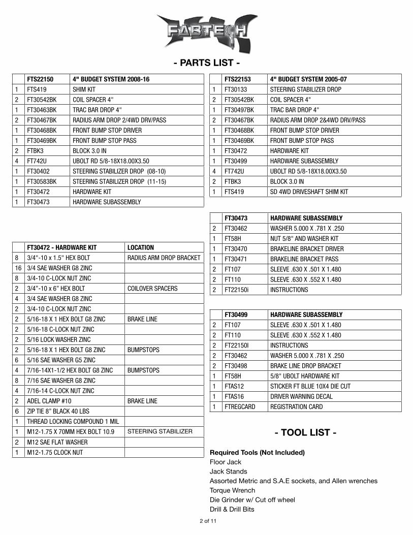
- PARTS LIST -
- TOOL LIST -
Required Tools (Not Included)Floor JackJack StandsAssorted Metric and S.A.E sockets, and Allen wrenchesTorque WrenchDie Grinder w/ Cut off wheelDrill & Drill Bits
2 of 11
FTS22150 4" BUDGET SYSTEM 2008-16
1 FTS419 SHIM KIT
2 FT30542BK COIL SPACER 4"
1 FT30463BK TRAC BAR DROP 4"
2 FT30467BK RADIUS ARM DROP 2/4WD DRV/PASS
1 FT30468BK FRONT BUMP STOP DRIVER
1 FT30469BK FRONT BUMP STOP PASS
2 FTBK3 BLOCK 3.0 IN
4 FT742U UBOLT RD 5/8-18X18.00X3.50
1 FT30402 STEERING STABILIZER DROP (08-10)
1 FT30583BK STEERING STABILIZER DROP (11-15)
1 FT30472 HARDWARE KIT
1 FT30473 HARDWARE SUBASSEMBLY
FTS22153 4" BUDGET SYSTEM 2005-07
1 FT30133 STEERING STABILIZER DROP
2 FT30542BK COIL SPACER 4"
1 FT30497BK TRAC BAR DROP 4"
2 FT30467BK RADIUS ARM DROP 2&4WD DRV/PASS
1 FT30468BK FRONT BUMP STOP DRIVER
1 FT30469BK FRONT BUMP STOP PASS
1 FT30472 HARDWARE KIT
1 FT30499 HARDWARE SUBASSEMBLY
4 FT742U UBOLT RD 5/8-18X18.00X3.50
2 FTBK3 BLOCK 3.0 IN
1 FTS419 SD 4WD DRIVESHAFT SHIM KIT
FT30472 - HARDWARE KIT LOCATION
8 3/4"-10 x 1.5" HEX BOLT RADIUS ARM DROP BRACKET
16 3/4 SAE WASHER G8 ZINC
8 3/4-10 C-LOCK NUT ZINC
2 3/4”-10 x 6” HEX BOLT COILOVER SPACERS
4 3/4 SAE WASHER G8 ZINC
2 3/4-10 C-LOCK NUT ZINC
2 5/16-18 X 1 HEX BOLT G8 ZINC BRAKE LINE
2 5/16-18 C-LOCK NUT ZINC
2 5/16 LOCK WASHER ZINC
2 5/16-18 X 1 HEX BOLT G8 ZINC BUMPSTOPS
6 5/16 SAE WASHER G5 ZINC
4 7/16-14X1-1/2 HEX BOLT G8 ZINC BUMPSTOPS
8 7/16 SAE WASHER G8 ZINC
4 7/16-14 C-LOCK NUT ZINC
2 ADEL CLAMP #10 BRAKE LINE
6 ZIP TIE 8” BLACK 40 LBS
1 THREAD LOCKING COMPOUND 1 MIL
1 M12-1.75 X 70MM HEX BOLT 10.9 STEERING STABILIZER
2 M12 SAE FLAT WASHER
1 M12-1.75 CLOCK NUT
FT30473 HARDWARE SUBASSEMBLY
2 FT30462 WASHER 5.000 X .781 X .250
1 FT58H NUT 5/8" AND WASHER KIT
1 FT30470 BRAKELINE BRACKET DRIVER
1 FT30471 BRAKELINE BRACKET PASS
2 FT107 SLEEVE .630 X .501 X 1.480
2 FT110 SLEEVE .630 X .552 X 1.480
2 FT22150i INSTRUCTIONS
FT30499 HARDWARE SUBASSEMBLY
2 FT107 SLEEVE .630 X .501 X 1.480
2 FT110 SLEEVE .630 X .552 X 1.480
2 FT22150I INSTRUCTIONS
2 FT30462 WASHER 5.000 X .781 X .250
2 FT30498 BRAKE LINE DROP BRACKET
1 FT58H 5/8" UBOLT HARDWARE KIT
1 FTAS12 STICKER FT BLUE 10X4 DIE CUT
1 FTAS16 DRIVER WARNING DECAL
1 FTREGCARD REGISTRATION CARD

Read this before you begin installation-
Check all parts to the parts list above before beginning installation. If any parts are missing contact Fabtech at 909-597-7800 and a replacement part will be sent to you immediately.
Read all instructions thoroughly from start to finish before beginning the installation. If these instructions are not properly followed severe frame, driveline and / or suspension damage may occur.
Check your local city and state laws prior to the installation of this system for legality. Do not install if not legal in your area.
Prior to the installation of this suspension system perform a front end alignment and record. Do not install this system if the vehicle alignment is not within factory specifications. Check for frame and suspension damage prior to installation.
The installation of this suspension system should be performed by two professional mechanics.
Use the provided thread locking compound on all hardware.
Do not combine this suspension system with any other lift device or parts.
This suspension must be installed with Fabtech shock absorbers.
Fabtech suspension systems may require that the front drive shaft be modified when used on gas engine trucks. This is done to give adequate clearance between the driveshaft and the factory exhaust. Fabtech does not recommend modifying the exhaust and or catalytic converters. Contact Fabtech for additional information.
WARNING- Installation of this system will alter the center of gravity of the vehicle and may increase roll over as compared to stock.
For technical assistance call: 909-597-7800 or e-mail: [email protected]
Recommend Tires and Wheels:
Use 35/12.50R18 tire w/ 18x9.5 wheels w/ 4-3/4” BS w/ required fenderwell trimmingUse 35/12.50R20 tire w/ 20x9 wheels w/ 5” BS w/ required fenderwell trimming
- PRE-INSTALLATION NOTES -
3 of 11

5. Remove the factory steering stabilizer from the frame mount and save the hardware. Remove the steering stabilizer frame bracket and save the hardware. Discard the frame bracket. Leave the steering stabilizer connected to the drag link. SEE FIGURE 3
6. Disconnect the sway bar links at the end of the sway bar and save the hardware. SEE FIGURE 4
- INSTRUCTIONS -
FRONT SUSPENSION
1. Disconnect the negative terminal on the battery. Jack up the front end of the truck and support the frame rails with jack stands. NEVER WORK UNDER AN UNSUPPORTED VEHICLE! Remove the front tires.
2. Remove the brake line and ABS lines from the front side and the rear side of the lower spring perch on the axle and save the hardware. SEE FIGURE 1
3. Supporting the front axle with two floor jacks, remove the front shocks and discard.
4. Lower the front axle allowing the coil springs to come free of tension and remove the coil springs. EXERCISE EXTREME CAUTION WHEN WORKING WITH COIL SPRINGS UNDER LOAD! SEE FIGURE 2
FIGURE 1
FIGURE 2
FIGURE 3
4 of 11
FIGURE 4
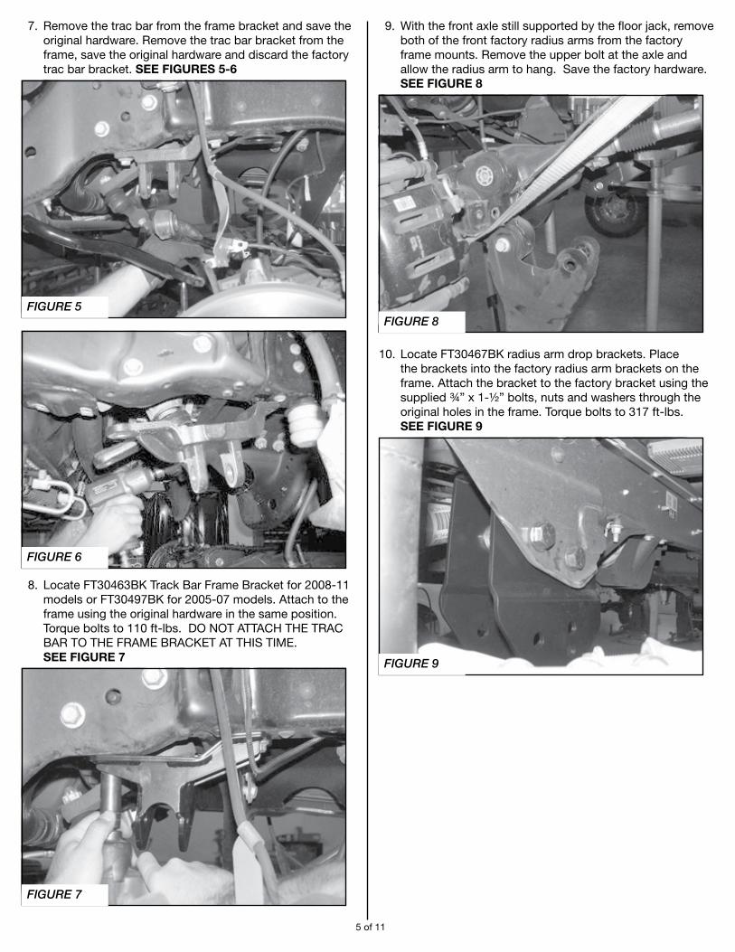
7. Remove the trac bar from the frame bracket and save the original hardware. Remove the trac bar bracket from the frame, save the original hardware and discard the factory trac bar bracket. SEE FIGURES 5-6
8. Locate FT30463BK Track Bar Frame Bracket for 2008-11 models or FT30497BK for 2005-07 models. Attach to the frame using the original hardware in the same position. Torque bolts to 110 ft-lbs. DO NOT ATTACH THE TRAC BAR TO THE FRAME BRACKET AT THIS TIME. SEE FIGURE 7
9. With the front axle still supported by the floor jack, remove both of the front factory radius arms from the factory frame mounts. Remove the upper bolt at the axle and allow the radius arm to hang. Save the factory hardware. SEE FIGURE 8
10. Locate FT30467BK radius arm drop brackets. Place the brackets into the factory radius arm brackets on the frame. Attach the bracket to the factory bracket using the supplied ¾” x 1-½” bolts, nuts and washers through the original holes in the frame. Torque bolts to 317 ft-lbs. SEE FIGURE 9
5 of 11
FIGURE 5
FIGURE 6
FIGURE 7
FIGURE 8
FIGURE 9
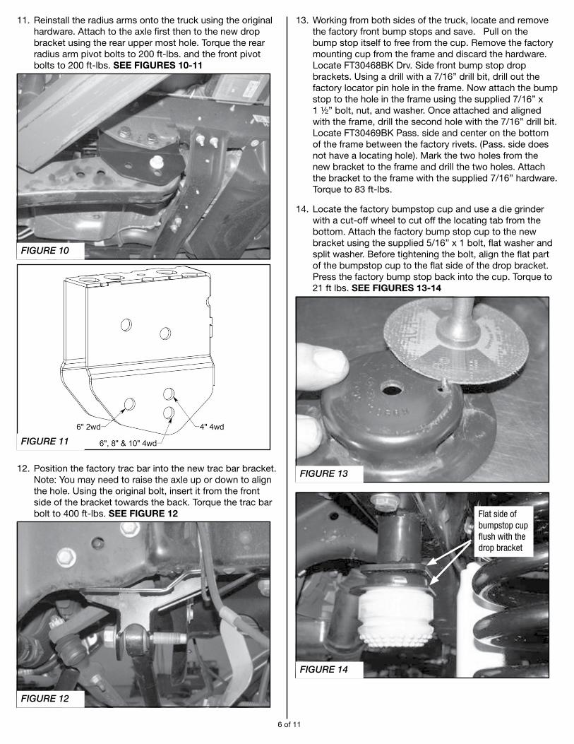
11. Reinstall the radius arms onto the truck using the original hardware. Attach to the axle first then to the new drop bracket using the rear upper most hole. Torque the rear radius arm pivot bolts to 200 ft-lbs. and the front pivot bolts to 200 ft-lbs. SEE FIGURES 10-11
12. Position the factory trac bar into the new trac bar bracket. Note: You may need to raise the axle up or down to align the hole. Using the original bolt, insert it from the front side of the bracket towards the back. Torque the trac bar bolt to 400 ft-lbs. SEE FIGURE 12
13. Working from both sides of the truck, locate and remove the factory front bump stops and save. Pull on the bump stop itself to free from the cup. Remove the factory mounting cup from the frame and discard the hardware. Locate FT30468BK Drv. Side front bump stop drop brackets. Using a drill with a 7/16” drill bit, drill out the factory locator pin hole in the frame. Now attach the bump stop to the hole in the frame using the supplied 7/16” x 1 ½” bolt, nut, and washer. Once attached and aligned with the frame, drill the second hole with the 7/16” drill bit. Locate FT30469BK Pass. side and center on the bottom of the frame between the factory rivets. (Pass. side does not have a locating hole). Mark the two holes from the new bracket to the frame and drill the two holes. Attach the bracket to the frame with the supplied 7/16” hardware. Torque to 83 ft-lbs.
14. Locate the factory bumpstop cup and use a die grinder with a cut-off wheel to cut off the locating tab from the bottom. Attach the factory bump stop cup to the new bracket using the supplied 5/16” x 1 bolt, flat washer and split washer. Before tightening the bolt, align the flat part of the bumpstop cup to the flat side of the drop bracket. Press the factory bump stop back into the cup. Torque to 21 ft lbs. SEE FIGURES 13-14
6 of 11
FIGURE 10
FIGURE 11
FIGURE 12
FIGURE 13
FIGURE 14
Flat side of bumpstop cup flush with the drop bracket

15. Locate the two FT30542BK coil spacers, two ¾-10 x 6’’ bolts and the two FT30462 washers. Install all the components into the factory coil bucket in the order shown below using the original factory upper coil isolator. Torque the ¾” bolts to 129 ft-lbs. SEE FIGURES 15-16 NOTE: Make sure bolt end does not contact the ABS module on driver side, bend the ABS module bracket slightly so contact is not made with the bolt end.
16. Using a floor jack, raise the front axle enough to compress the front coils approx. 1”. Locate the front shocks (Performance FTS7236 or DL FTS810961) and install onto the truck. Note: Some shock mounts will require cutting a ¼” from the top of the factory shock tab. If required, use a die grinder with a cut-off wheel and remove the top ¼” of the tab. Sand and paint bare/exposed metal. SEE FIGURES 17-19
7 of 11
3/4"-10 NUT3/4" WASHER
FT30462
FACTORYSPRINGPERCH
FT30542K
3/4" WASHER
3/4"-10 X 6" LONGHEX BOLT
FACTORY SPRINGISOLATOR
FACTORY SPRING
FIGURE 15
FIGURE 16
FIGURE 17
FIGURE 18

17. Remove the factory brake line brackets on the driver side and passenger side of the vehicle. Discard the brackets. SEE FIGURE 20
For 05-10 models:
18. Locate the factory brake line mount on the front side of the frame. Remove the bracket from the frame and save the hardware. Locate FT30470 Front Brake Line Drop Bracket driver for 08-10 models or FT30498 for 05-07 models and attach to the frame using the original hardware in the factory brake line hole. Using the supplied 5/16” hardware, attach the factory brake line to the new drop bracket. You will need to carefully bend the hard line down to meet the new brake line bracket. USE CARE NOT TO DAMAGE THE HARD LINE.
For 2011 and up models:
19. Locate the factory brake line mount on the front side of the frame. Remove the bracket from the frame and save the hardware. Locate FT30470 Front Brake Line Drop Bracket driver and attach to the frame using the original hardware in the factory brake line hole. Remove the brake line junction block from the factory bracket and rotate it 180 degrees and reinstall it. To do this, slightly loosen the hard line at the junction block. Do not remove the line allowing air to enter the brake system. SEE FIGURES 21-24 2011 factory configured brake line shown below
8 of 11
FIGURE 19
FIGURE 20
FIGURE 21
FIGURE 22

2011 reconfigured brake line with FT30470 Drop Bracket shown below
20. Remove factory steering stabilizer from factory mount. Remove factory frame mount.
21. Locate FT30402 (2008-10), FT30133 (2005-07) or FT30583BK (2011- 15) steering stabilizer drop bracket and install in the factory location using the original hardware. Torque to 50 ft-lbs. Reattach the factory stabilizer to the frame bracket using the original hardware. SEE FIGURES 25-27
9 of 11
FIGURE 24
FIGURE 23
FIGURE 25
FIGURE 26
FIGURE 27
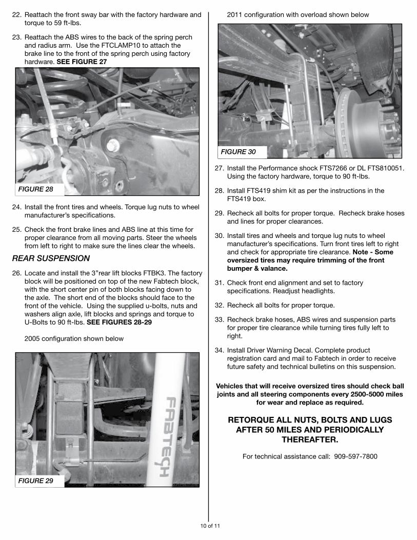
22. Reattach the front sway bar with the factory hardware and torque to 59 ft-lbs.
23. Reattach the ABS wires to the back of the spring perch and radius arm. Use the FTCLAMP10 to attach the brake line to the front of the spring perch using factory hardware. SEE FIGURE 27
24. Install the front tires and wheels. Torque lug nuts to wheel manufacturer’s specifications.
25. Check the front brake lines and ABS line at this time for proper clearance from all moving parts. Steer the wheels from left to right to make sure the lines clear the wheels.
REAR SUSPENSION
26. Locate and install the 3’’rear lift blocks FTBK3. The factory block will be positioned on top of the new Fabtech block, with the short center pin of both blocks facing down to the axle. The short end of the blocks should face to the front of the vehicle. Using the supplied u-bolts, nuts and washers align axle, lift blocks and springs and torque to U-Bolts to 90 ft-lbs. SEE FIGURES 28-29 2005 configuration shown below
2011 configuration with overload shown below
27. Install the Performance shock FTS7266 or DL FTS810051. Using the factory hardware, torque to 90 ft-lbs.
28. Install FTS419 shim kit as per the instructions in the FTS419 box.
29. Recheck all bolts for proper torque. Recheck brake hoses and lines for proper clearances.
30. Install tires and wheels and torque lug nuts to wheel manufacturer’s specifications. Turn front tires left to right and check for appropriate tire clearance. Note - Some oversized tires may require trimming of the front bumper & valance.
31. Check front end alignment and set to factory specifications. Readjust headlights.
32. Recheck all bolts for proper torque.
33. Recheck brake hoses, ABS wires and suspension parts for proper tire clearance while turning tires fully left to right.
34. Install Driver Warning Decal. Complete product registration card and mail to Fabtech in order to receive future safety and technical bulletins on this suspension.
Vehicles that will receive oversized tires should check ball joints and all steering components every 2500-5000 miles
for wear and replace as required.
RETORQUE ALL NUTS, BOLTS AND LUGS AFTER 50 MILES AND PERIODICALLY
THEREAFTER.
For technical assistance call: 909-597-7800
10 of 11
FIGURE 29
FIGURE 30
FIGURE 28

- Product Warranty and Warnings -
Fabtech provides a Limited Lifetime Warranty to the original retail purchaser who owns the vehicle, on which the product was originally installed, for defects in workmanship and materials.
The Limited Lifetime Warranty excludes the following Fabtech items; bushings, bump stops, ball joints, tie rod ends, limiting straps, cross shafts, heim joints and driveshafts. These parts are subject to wear and are not considered defective when worn. They are warranted for 60 days from the date of purchase for defects in workmanship.
Dirt Logic and Performance Coilover take apart shocks are considered a serviceable shock with a one year warranty on leakage only. Service seal kits are available separately for future maintenance. All other shocks are covered under our Limited Lifetime Warranty.
Fabtech does not warrant any product for finish, alterations, modifications and/or installation contrary to Fabtech’s instructions. Alterations to the finish of the parts including but not limited to painting, powder coating, plating and/or welding will void all warranties. Some finish damage may occur to parts during shipping, which is considered normal and is not covered under warranty.
Fabtech products are not designed nor intended to be installed on vehicles used in race applications or for racing purposes or for similar activities. (A “RACE” is defined as any contest between two or more vehicles, or any contest of one or more vehicle against the clock, whether or not such contest is for a prize). This warranty does not include coverage for police or taxi vehicles, race vehicles, or vehicles used for government or commercial purposes. Also excluded from this warranty are sales outside of the United States of America.
Installation of most suspension products will raise the center of gravity of the vehicle and will cause the vehicle to handle differently than stock. It may increase the vehicle’s susceptibility to a rollover, on road and off road, at all speeds. Extreme care should be taken to operate the vehicle safely at all times to prevent rollover or loss of control resulting in serious injury or death. Fabtech front end Desert Guards may impair the deployment or operation of vehicles equipped with supplemental restraining systems/air bag systems and should not be installed if the vehicle is equipped as so.
Fabtech makes every effort to ensure suspension product compatibility with all vehicles listed on the website, but due to unknown auto manufacturer’s production changes and/or inconstancies by the auto manufacturer, Fabtech cannot be responsible for 100% compatibility, including the fitment of tire and wheel sizes listed. The Tire and Wheel sizes listed in Fabtech’s website are only a guideline for street driving with noted fender trimming. Fabtech is not responsible for damages to the vehicle’s body or tires. Fabtech is not responsible for premature wear of factory components due to the installation of oversized tires and wheels.
Fabtech’s obligation under this warranty is limited to the repair or replacement, at Fabtech option, of the defective product only. All costs of removal, installation or re-installation, freight charges, incidental or consequential damages are expressly excluded from this warranty. Fabtech is not responsible for damages and/or warranty of other vehicle parts related or non related to the installed Fabtech product. This warranty is expressly in lieu of all other warranties expressed or implied. This warranty shall not apply to any product that has been subject to accident, negligence, alteration, abuse or misuse as determined by Fabtech.
Fabtech suspension components must be installed as a complete system including shocks as shown on our website. All warranties will become void if Fabtech parts are combined and/or substituted with other aftermarket suspension products. Combination and/or substitution of other aftermarket suspension parts may cause premature wear and/or product failure resulting in an accident causing injury or death. Fabtech does not warrant products not manufactured by Fabtech.
Depending on the condition of the factory suspension components retained after the installation of a Fabtech suspension not all vehicles may have the same ride stance front to rear as described in the website. The blue color of suspension components shown in all Fabtech photographs are for display purposes only. Majority of all Fabtech components will be black specifically where noted with part numbers ending in BK.
Installation of Fabtech product may void the vehicles factory warranty; it is the consumer’s responsibility to check with their local vehicle’s dealer for warranty disposition before the installation of the product. Some state laws may prohibit modification of suspension to a vehicle in whole or in part. It is the responsibility of the installer and consumer to consult local laws prior to the installation of any Fabtech suspension product to comply with such written laws.
It is the responsibility of the distributor and/or the retailer to review all warranties and warnings of Fabtech products with the consumer prior to purchase.
Fabtech reserves the right to super cede, discontinue, change the design, finish, part number and/or application of parts when deemed necessary without written notice. Fabtech is not responsible for misprints or typographical errors within the website or price sheet. For the most recent Product Warranty and Warnings visit our website www.fabtechmotorsports.com
Instruction Sheet Part# - FT22150i REV SE 05/16/17
11 of 11