installation keys – cold weather focus - gsdia.org conference handouts/3 heger... · water is...
TRANSCRIPT

30th Annual Granite State Conference March 13, 2017
Heger Installation Keys © 1
Installation Keys –Cold Weather Focus
Dr. Sara [email protected]
http://septic.umn.eduMarch 13, 2017
Installation keys overview
Material issuesKeeping soil conditions natural
• Keeping soil nature at infiltrative surface
• Compaction and smearing
Cold climate considerations
Proper installation is REALLY important!
Using good material and techniques are critical for long term system performanceIf site or soils are negatively impacted the ability for site to treat and accept wastewater long term will be decreased
Media specifications
Media specifications
Installer must make sure media available meets specifications of system designer and codes!
Know what material to ask forGet documentation that material is what you orderedKnow what it should look likeKnow how to double check if neededDocument with pictures
Treatment media - sand
Treatment media in:Filters Mounds
Washed to be free of silt and clay particles (fines <5%) to prevent system failureCheck design & local code for allowable amount
30th Annual Granite State Conference March 13, 2017
Heger Installation Keys © 2
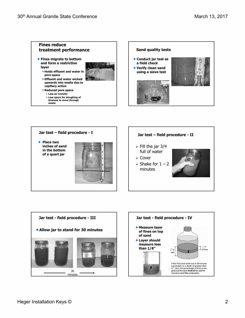
Fines reduce treatment performance
Fines migrate to bottom and form a restrictive layer
Holds effluent and water in pore spaceEffluent and water wicked upwards into media due to capillary actionReduced pore space
• Less air transfer • Less space for sloughing of
biomass to move through media
Sand quality tests
Conduct jar test as a field checkVerify clean sand using a sieve test
Jar test – field procedure - I
Place two inches of sand in the bottom of a quart jar
Jar test – field procedure - II
Fill the jar 3/4 full of water
Cover Shake for 1 – 2
minutes
Jar test - field procedure - III
Allow jar to stand for 30 minutes
30 minutes
Jar test - field procedure - IV
Measure layer of fines on top of sand Layer should measure less than 1/8”
30th Annual Granite State Conference March 13, 2017
Heger Installation Keys © 3
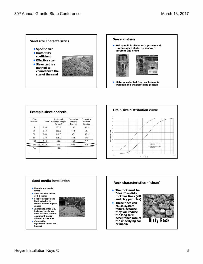
Sand size characteristics
Specific size Uniformity coefficientEffective sizeSieve test is a method to characterize the size of the sand
Sieve analysis
Soil sample is placed on top sieve and run through a shaker to separate different size grains
Material collected from each sieve is weighed and the point data plotted
Example sieve analysis
SizeNumber mm
IndividualRetained Weight
(grams)
CumulativePercentRetained
CumulativePercentPassing
8 2.36 127.0 18.7 81.316 1.18 189.5 46.5 53.530 0.60 140.0 67.1 32.950 0.30 105.0 82.5 17.5100 0.15 93.0 96.2 3.8200 0.075 25.5 99.9 0.1Pan 1.00
FINES
Grain size distribution curve
Sand media installation
Mounds and media filtersSand installed in lifts of 6-8 inchesFoot compaction and light watering to reduce volume of pore spacesIn mounds, after 6-12 inches of media has been installed tracked equipment maybe allowed across area Compaction equipment should not be used
Rock characteristics - “clean”
The rock must be “clean” as dirty rock has fines (silt and clay particles)These fines can cause system failure because they will reduce the long term acceptance rate of the underlying soil or media

30th Annual Granite State Conference March 13, 2017
Heger Installation Keys © 4
Keeping soil conditions natural
Concerns for installation on wet sites
Dewatering may be neededSoil smearing and compaction more likely
Soil must be treated carefully
Check weather before starting construction & be prepared
RoughingScarification -process of scratching the absorption area
Stake firstProper elevationsGreen side down
BackhoeNever drive on loosened soil
Do not smear or compact soilCheck if soil is too dry or wet prior
Field testing of soil moisture
Plastic limit procedure
Grab a ped/clump of soil from infiltrative surface
• Do not add water
Try to roll into a wire/pencil
Field testing of soil moisture
If wire/pencil is:1/8 inch in diameter and 2 inches long without crumbling
• Moisture content is above plastic limit
• Construction should NOT proceed
Can the soil be too dry?
Yes! Soils which are too dry when worked are smeared by the bucket Fine soil particles separated and stratified into layers Stratification impairs the movement of wastewater due to silty layer formation

30th Annual Granite State Conference March 13, 2017
Heger Installation Keys © 5
Topsoil benefits
Typically soil for treatment and dispersalRemoving increases likelihood of damaging soilMay assist with nitrogen removal processTopsoil has be shown to be effective at removing chemicals of emerging concern
Maintaining natural soil conditions
Soil located at or near the soil surface is generally the best for:
Treatment Dispersal Oxygen-transfer Evapotranspiration Natural biological activity
SOIL BIOTA POPULATIONVS
SOIL DEPTH
98.7%0.9%
0.4%
16 inches
30 inches
Protecting exposed natural soil
If site has been scarified, immediately cover with media to prevent
Damage Contamination
When you can't cover exposed soil immediately, protect area with tarp
Maintain pore space
Pore space is essential for:
Oxygen transferWater movement

30th Annual Granite State Conference March 13, 2017
Heger Installation Keys © 6
Oxygen levels with depth case study
DepthWet Time Periods
Dry TimePeriod
Inches (mg/L) (mg/L)3.9 13.7 20.69.8 12.7 19.817.7 12.2 18.835.4 7.6 17.347.2 7.8 16.4
Techniques to maintain natural soil conditions of infiltrative surface
Do not drive excavation equipment or other vehicles over Limit foot traffic Rake sidewalls of trenches and beds Use low ground pressure equipmentPosition equipment upslope of system when placing media
Soil considerations for installation on wet sites
Excavation only when:
Soil is dry enoughSoil is below the plastic limit • Field check of
moisture content
Soil is not frozen
Soil smearing
Smearing: the spreading and smoothing of soil particles by sliding pressure
Any sandy loam or finer textured soil can be susceptible to smearing if enough water is presentThis is why we test the plastic limit before construction
Smearing Soil compaction3 different things
1. Compression is loss of soil volume
2. CompactionTranslocation and resorting sand, silt, and clay particlesDestruction of soil aggregatesCollapse of aeration pores

30th Annual Granite State Conference March 13, 2017
Heger Installation Keys © 7
3. Consolidation
Deformation of the soil destroying any pore space and structure
Water is squeezed from the soilProcess leads to increased internal bonding and soil strength as more particle to particle contacts are made and pore space is eliminated
Compaction
If a piece of equipment could run over an area 10 consecutive times and one could measure soil density after each pass one would find the following:
70% of total compaction of all 10 passes occur with first pass
10% of total compaction of all 10 passes with the second pass
5% of total compaction of all 10 passes with the third pass
38
Compaction under dual tires
17 psi 30 psi
Compaction under different tire design
40
Large PSI per surface contact
41
Soil compaction by weight of machine and oxygen diffusion rates
10 cm = ~ 4 inches

30th Annual Granite State Conference March 13, 2017
Heger Installation Keys © 8
Compaction with:axle load versus soil moisture
43
Strategies to reduce compaction
Reduce tire pressure to minimal allowable pressuresUse tracks or duals to replace singlesInstall larger diameter tires to increase length of footprint
Work from upslope of soil treatment system whenever possibleUse smaller equipment -Avoid oversizedCombine field operationsProtect the soil treatment area
Mark off areas where vegetation is to stay Mark off areas where traffic needs to
be voided
Keep traffic off This can be from traffic
46
Reserve area ?Soil compaction
30th Annual Granite State Conference March 13, 2017
Heger Installation Keys © 9
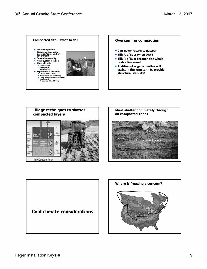
Compacted site – what to do?
Avoid compactionDiscuss options with Designer/Local unit of governmentDetermine severity Move system locationTime will help
Freeze/thawRoot activityWeathering
Experimental methodsLower loading ratesMechanical soil fracturingDeep plowing/ripping – shank implementRemoving & backfilling
Overcoming compaction
Can never return to naturalTill/Rip/Bust when DRY!Till/Rip/Bust through the whole restrictive zone!Addition of organic matter will assist in the long term to provide structural stability!
50
Tillage techniques to shatter compacted layers
51
Must shatter completely through all compacted zones
52
Cold climate considerations
Where is freezing a concern?

30th Annual Granite State Conference March 13, 2017
Heger Installation Keys © 10
Extreme winters
No snow = no insulationFrost recorded at depths greater then usualMunicipal sewage and water lines freeze too!
Can I install in frozen soils?
Any frost is too much frost for an above- grade systemFor below grade trenches frost could be present, however cannot extend to the depth of the required sidewall or bottom area of the trench/bedSnow should be removed with caution
Frozen soil - why are they bad?
No way to test the plastic limit
Wet fallScarification will not work
Soil can be frozen solid Large clumps instead of exposing natural soil structureShattering in dry frozen soils
If scarified when frozen as the soil thaws it can “seal off” the scratched areaThe large frozen clumps will also hamper constructability
Frozen soil-why are they bad?
Stock piles of sandy/loamy soil material (cover) or topsoil should not be allowed to freezeAttempting to use this material for cover will result in:
Uneven cover thicknessesIncreased erosion potentialDifficulties in establishing vegetative coverPoor frost protection
Why do systems freeze?
Lack of snow cover, cold temps = frozen soilCompacted snow or soilNo plant coverLow or no water use (including leaking fixtures, high efficiency furnaces)Pipes not draining = saturated flow of waterCold air entering the systemWater logged system = saturated flow of waterEnough contact time to freeze
Immediate tasks when a system freezesTell homeowner to
shut pump off if part of the system
If soil treatment system is not frozen
Jet or steam out the lines
Heat tape or thermostatically-controlled heat cables can be used to wrap pipes.
Heat tape for inside pipe exists too

30th Annual Granite State Conference March 13, 2017
Heger Installation Keys © 11
Septic heater?
Add a heater • STEP-HEAT - low voltage heating of small or
large storage tanks• Stock tank heaters• Septic heater
Send camera down line to see if pipe has fall and where blockage isThaw system –heat blanketsUse tanks as holding tanks until spring
• Minimize water useDo NOT
• add antifreeze, salt or an additive• pump out sewage onto the ground surface • start a fire over the system• run water continually to try to unfreeze system.
Immediate Tasks when System Freezes Cont’d
1. Pipe From House to Tank
Check for leaking fixtures and low water using devices such as high efficiency furnacesVerify that pipe has proper fall
1 inch in 8 feet –2 inches in 8 ftLaser, camera or backhoe
2. Septic or Pump Tank Froze
Verify baffles are still in place and have not been damagedVerify that tank has not crackedAdd Styrofoam over tankNotify homeowners that if emergency pumping was done not through the manhole = no maintenanceVerify pump and floats working properlyBring manhole with pump to the surface, add Styrofoam under lid or add mulch over the top in fall.Insulate!
3. Pipe to Soil Treatment Area
Verify proper fall and leaky fixtures
Make sure drain back is set up right
Replace all check valves and systems set up with effluent draining through the pump
¼ inch weep hole located in the lowest portion of piping in manhole (typically elbow)
4. Frozen Soil Treatment Area
If wet or soggy in fall the system was a problem waiting to happen
If froze during the winter and sewage came to the surface
Future pathway for sewage
Add topsoil or rework area
Check distributionDrop and distribution
boxesPressure distribution
system

30th Annual Granite State Conference March 13, 2017
Heger Installation Keys © 12
Freeze Prevention Techniques for New Systems
Use insulated pipe whenever appropriate
High trafficShallow
Add insulation over tanks and manhole risers that come to the surface
Thermal Conductivity for Various Materials
Thermal conductivity is a measure of how much energy/heat is being transferred through an area
Material Thermal Conductivity (MJ/m2. d . oC)
Polystyrene 0.0026
Snow 0.0056Straw 0.0078Soil 0.0449
Sand 0.0302Clay 0.1123
Soil, Straw or Insulation?
Make sure system has minimum cover
12” minimum recommended
2 inches of polystyrene = 35 inches of soil
6 inches of straw = 35 inches of soil
Insulation blankets
If installed prior to freezing conditions trap the heat of the soil and reduce freezing problemsWaterproof, it sheds late fall rain and holds snow for added insulation
Construction techniques for cold climates
Key techniquesKeep proper slope on pipesInsulate where appropriateBed pipes properly to prevent dips
Pipe sleeving
Use in areas where pipe needs additional support
Under driveways, roads, structuresWastewater pipe close to water lines or crosses water lines.Underlying soil is disturbed

30th Annual Granite State Conference March 13, 2017
Heger Installation Keys © 13
Pipe sleeving methods
Place a larger andstronger pipe around smaller pipe:
Helps support pipePrevents bowing
• Where debris gets caught
Spray insulation:• Prevents soil backfill
from filling pipe
Construction techniques for cold climates
Tanks and pretreatment units
Insulate when there is less than 2 feet of soil cover
Soil treatment system Limit traffic over systemVegetation is a critical part of natural insulation
• Vigorous growth in the fall is advantageous
• Fall installations should have temporary insulation – place light mulch material
Educational materials
Generic CustomizedQuestions
& more information
septic.umn.eduH2OandM.com