installation manual frog-a / frog-av / frog-ae vartai... · 2018-05-07 · 500 650 500 24h page 6 -...
TRANSCRIPT

UNDERGROUND OPERATOR FOR SWING GATES
Installation manual
FROG-A / FROG-AV / FROG-AE
English EN
119AS45EN

Pag
e 22
-
Man
ual
cod
e: 1
19A
S4
5EN
119
AS4
5EN
ver
. 66
05/2
014
©
CA
ME c
ance
lli a
uto
mat
ici S
.p.A
- T
he
dat
a an
d in
form
atio
n p
rovi
ded
in t
his
man
ual
are
subje
ct t
o ch
ange
at a
ny t
ime
with
out
prior
not
ice
by
CA
ME C
ance
lli A
uto
mat
ici S
.p.a
.
ENGLISH
Introduction
• Use this product only for the specifi c purpose for which it is designed. Any other use is therefore improper and dangerous. CAME Cancelli Automatici S.p.A. is not liable for any damage due to improper, erroneous and unrea-sonable use • Keep these warnings together with the installation and users' manual for the automation system.
Before installing
(check what's there: if you fi nd something wrong, proceed only after correcting the problem so the equipment is safe to use)• Check that the part you want to automate is in good mechanical condition, that it is balanced and aligned, and that it opens and closes properly. Make sure you have suitable mechanical stops • If the operator will be installed less than 2.5 m from the fl oor or from any other access level, check whether you need additional protections and/ or warnings • With pedestrian doors framed into the doors that will be automated, a system must be in place to block their opening during movement • Make sure the opening of the automated door leaf does not cause any trapping situations involving any surrounding fi xed parts • Do not install the operator upside down or on any elements that may bend. If necessary, add suitable reinforcements at the fastening points • Do not install on sloping ground (only install on fl at ground) • Check that any watering devi-ces cannot wet the gearmotor from the bottom upwards.
Installation
• Properly signal and demarcate the entire site prevent any careless people from entering the works area • Be careful when handling operators that weigh more than 20 kg (see installation manual. If such is the case, make sure you have proper hoisting equipment. All opening commands (buttons, key selec-tors, magnetic card readers, and so on) must be installed at least 1.85 M from the gate's area of movement, or so that they are unreachable from the outside. Moreover, the direct commands (from buttons, swipe cards, and so on) must be installed 1.5 m high off the ground and must not be reachable by the public • All "hold-to-run" commands must be placed where the operating gate leaves and transit areas are completely visible. • Apply a permanent label that shows the position of the release device • Before turning over the instal-lation to the user, check that the system conforms to standards EN 12453 and EN12445 (impact testing), making sure the device has been properly adjusted and that the safety and protection and release devices function properly • Where necessary apply the Warning Signs so that they are clearly visible (e.g. the gate plate)
Instructions and special recommendations for users
• Keep the barrier's areas of operations unobstructed. Check that the photo-cells are free of any vegetation blocking them, and that there are no obstacles to the free movement of the operator. Do not allow children to play with the fi xed command devices, or in the barrier's area of operation. Keep transmitters and any other command devices away from children, to prevent the operator from being activated by mistake • Frequently check the system, to scan for any anomalies or wear and tear in the moving structures, the operator's com-ponents, all fastening points and devices, the cables and accessible connec-tions. Keep any jointed parts like hinges lubricated and clean of debris and the guide-sleds free of any friction • Perform functional checks to the photocells and sensitive edges every six months. To check that the photocells work pro-perly, wave an object in front of them during closing; if the operator inverts its direction of travel or blocks movement, then the photocells are working properly. This is the only maintenance job that can be done to the gate when it is powered up. Ensure proper cleaning of the glass on the photocells (use a slightly damp cloth); do not use any solvents or other chemical products that may ruin the devices) • Should any repairs or changes to the system settings be needed, release the operator and refrain from using it until safety condi-tions have been restored • Cut the power off before releasing the operator for manual opening, to avoid any hazardous situations. Check instructions • It is FORBIDDEN for users to perform ANY OPERATIONS THAT ARE NOT EXPRESSLY REQUESTED OF SAID USERS in the manuals. Any repairs, adjustments or extra-ordinary maintenance, EXCLUSIVELY CALL TECHNICAL ASSISTANCE • Log any service jobs onto the periodic maintenance journal.
Special instructions and recommendations for everyone
• Keep away from the hinges and any moving mechanical parts • Stay out of the operating range of the operator while it is moving • Do not oppose the movement of the operator as this may result in danger • Always be careful around the dangerous parts, which must be properly indicated with warning signs and black and yellow stripes • When using a selector switch or a main-tained-action mode command, keep checking that no persons come within the operating range of the moving parts, until the command is released • The gate may move at any moment without warning. Always cut off the main electric power supply before performing any cleaning or maintenance.
WARNING!important safety instructions:
READ CAREFULLY!
Hand crushing hazard
Danger high voltage
No transit during operation
13
45
2
Pag
e 33
-
Man
ual
cod
e: 1
19A
S4
5EN
119
AS4
5EN
ver
. 66
05/2
014
©
CA
ME c
ance
lli a
uto
mat
ici S
.p.A
- T
he
dat
a an
d in
form
atio
n p
rovi
ded
in t
his
man
ual
are
subje
ct t
o ch
ange
at a
ny t
ime
with
out
prior
not
ice
by
CA
ME C
ance
lli A
uto
mat
ici S
.p.a
.
ENGLISH
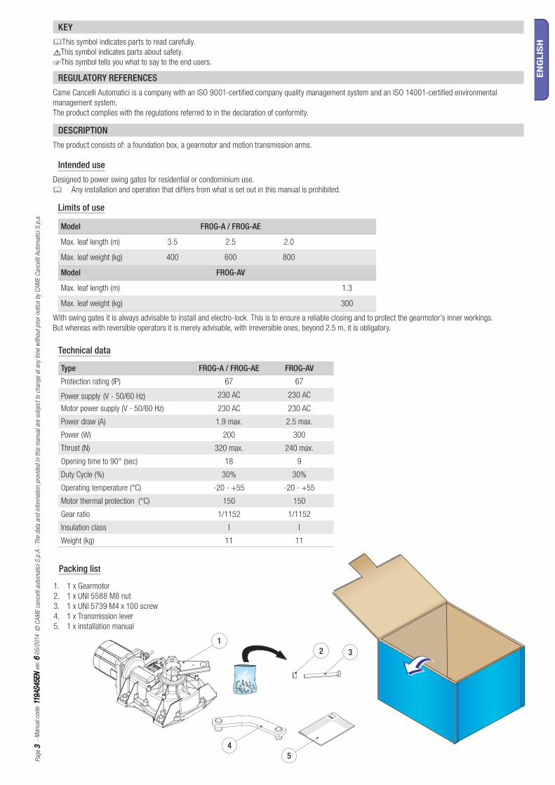
With swing gates it is always advisable to install and electro-lock. This is to ensure a reliable closing and to protect the gearmotor’s inner workings.
But whereas with reversible operators it is merely advisable, with irreversible ones, beyond 2.5 m, it is obligatory.
KEY
This symbol indicates parts to read carefully.
⚠This symbol indicates parts about safety.
☞This symbol tells you what to say to the end users.
DESCRIPTION
The product consists of: a foundation box, a gearmotor and motion transmission arms.
Intended use
Designed to power swing gates for residential or condominium use.
Any installation and operation that differs from what is set out in this manual is prohibited.
Model FROG-A / FROG-AE
Max. leaf length (m) 3.5 2.5 2.0
Max. leaf weight (kg) 400 600 800
Model FROG-AV
Max. leaf length (m) 1.3
Max. leaf weight (kg) 300
Packing list
1. 1 x Gearmotor
2. 1 x UNI 5588 M8 nut
3. 1 x UNI 5739 M4 x 100 screw
4. 1 x Transmission lever
5. 1 x installation manual
REGULATORY REFERENCES
Came Cancelli Automatici is a company with an ISO 9001-certified company quality management system and an ISO 14001-certified environmental
management system.
The product complies with the regulations referred to in the declaration of conformity.
Limits of use
Technical data
Type FROG-A / FROG-AE FROG-AV
Protection rating (IP) 67 67
Power supply (V - 50/60 Hz) 230 AC 230 AC
Motor power supply (V - 50/60 Hz) 230 AC 230 AC
Power draw (A) 1.9 max. 2.5 max.
Power (W) 200 300
Thrust (N) 320 max. 240 max.
Opening time to 90° (sec) 18 9
Duty Cycle (%) 30% 30%
Operating temperature (°C) -20 - +55 -20 - +55
Motor thermal protection (°C) 150 150
Gear ratio 1/1152 1/1152
Insulation class I I
Weight (kg) 11 11

2
6
5
8
10
9
1
3
4
7
10 11
12
13 14
15
5
2
8
8
9
10
11
3
12
12
1
12
3
7
4
6
9
7
1
7
Pag
e 44
-
Man
ual
cod
e: 1
19A
S4
5EN
119
AS4
5EN
ver
. 66
05/2
014
©
CA
ME c
ance
lli a
uto
mat
ici S
.p.A
- T
he
dat
a an
d in
form
atio
n p
rovi
ded
in t
his
man
ual
are
subje
ct t
o ch
ange
at a
ny t
ime
with
out
prior
not
ice
by
CA
ME C
ance
lli A
uto
mat
ici S
.p.a
.
ENGLISH
Example of a system
1. Gearmotor with foundation box
2. Control panel
3. Junction box
4. Key selector
5. Antenna
6. Flashing light
7. Photocells
8. Photocell post
9. Latch
10. Inspection chamber
11. Drainage chamber
12. Mechanical stop
Description of the components
1. Gearmotor
2. Transmission lever
3. Gearmotor arm
4. Limit switch adjusting screw when closing
5. Couple release lever
6. Mounting bracket to gate
7. Limit switch adjusting screw when closing
8. Foundation box
9. Casing hole
10. Cover fixing screw
11. UNI 5588 M12 nut
12. UNI 6592 12 washer
13. Drainage hole
14. Cable routing hole
15. Pin

67
330405
160
60
100
Pag
e 55
-
Man
ual
cod
e: 1
19A
S4
5EN
119
AS4
5EN
ver
. 66
05/2
014
©
CA
ME c
ance
lli a
uto
mat
ici S
.p.A
- T
he
dat
a an
d in
form
atio
n p
rovi
ded
in t
his
man
ual
are
subje
ct t
o ch
ange
at a
ny t
ime
with
out
prior
not
ice
by
CA
ME C
ance
lli A
uto
mat
ici S
.p.a
.
ENGLISH
GENERAL INSTALLATION INSTRUCTIONS
⚠ Installation must be carried out by qualified and experienced personnel in compliance with applicable regulations.
Preliminary checks
⚠ Before installing the operator:
• Provide a suitable single-pole disconnection device, with a maximum of 3 mm between the contacts, to disconnect the power supply;
• Prepare suitable piping and ducts for routing the electrical cables, ensuring protection against mechanical damage;
• Prepare a drain pipe to prevent stagnation that may cause oxidation;
• Make sure that any connections within the container (made to ensure the continuity of the protection circuit) are fitted with additional insulation
compared to the other internal conductor parts;
• Make sure the gate structure is sturdy enough, that the hinges are in proper working order and that there is no friction between the moving and fixed parts;
• Make sure there are opening and closing mechanical stops.
Tools and materials
Make sure you have all the tools and materials you will need for the installation at hand to work in total safety and compliance with current standards and
regulations. The figure shows some examples of installer’s tools.
Types of cables and minimum thicknesses
Connection Cable type Cable length1 < 10 m
Cable length10 < 20 m
Cable length20 < 30 m
Control panel power supply 230 V
FROR CEI
20-22
IEC EN
50267-2-1
3G x 1.5 mm2 3G x 1,5 mm2 3G x 2.5 mm2
Motor power supply 230 V 3G x 1,5 mm2 3G x 1.5 mm2 3G x 2.5 mm2
Flashing light 2 x 0.5 mm2 2 x 1 mm2 2 x 1.5 mm2
Photocell transmitters 2 x 0.5 mm2 2 x 0.5 mm2 2 x 0.5 mm2
Photocell receivers 4 x 0.5 mm2 4 x 0.5 mm2 4 x 0.5 mm2
Control and safety devices 2 x 0.5 mm2 2 x 0.5 mm2 2 x 0.5 mm2
Encoder TWISTED max. 30 m
Antenna RG58 max. 10 m
N.B. : If the cables differ in length from what shown in the table, the cable cross-section is determined according to the actual current draw of the devices
connected and according to the provisions of the IEC EN 60204-1 standard.
For connections that require several, sequential loads, the sizes given on the table must be re-evaluated based on actual power draw and distances. When
connecting products that are not specified in this manual, please refer to the documentation provided with said products.
Dimensions (mm)

500
650
500
24h
Pag
e 66
-
Man
ual
cod
e: 1
19A
S4
5EN
119
AS4
5EN
ver
. 66
05/2
014
©
CA
ME c
ance
lli a
uto
mat
ici S
.p.A
- T
he
dat
a an
d in
form
atio
n p
rovi
ded
in t
his
man
ual
are
subje
ct t
o ch
ange
at a
ny t
ime
with
out
prior
not
ice
by
CA
ME C
ance
lli A
uto
mat
ici S
.p.a
.
ENGLISH
INSTALLATION
⚠ The following illustrations are only examples, given that the space for securing the operator and accessories varies depending on the overall dimensions.
The installation technician is responsible for choosing the most suitable solution.
the figures below illustrate the installation of the right-hand foundation box.
Laying the corrugated pipes and inspection chambers
Make the hole for the box.
Prepare the junction boxes and corrugated pipes necessary for connection to the inspection chamber and the drain pipe.
The number of tubes depends on the type of system installed and any accessories.
Installing the foundation box
Lean the box against the pillar making sure that the corrugated pipes and the drain pipe pass through the designated holes.
Fill the hole with concrete.
Position the box level with the ground and place the pin in line with the upper gate hinge. Wait at least 24h to cure.
Clean any remaining concrete from inside the box.
67 mm
Pag
e 77
-
Man
ual
cod
e: 1
19A
S4
5EN
119
AS4
5EN
ver
. 66
05/2
014
©
CA
ME c
ance
lli a
uto
mat
ici S
.p.A
- T
he
dat
a an
d in
form
atio
n p
rovi
ded
in t
his
man
ual
are
subje
ct t
o ch
ange
at a
ny t
ime
with
out
prior
not
ice
by
CA
ME C
ance
lli A
uto
mat
ici S
.p.a
.
ENGLISH
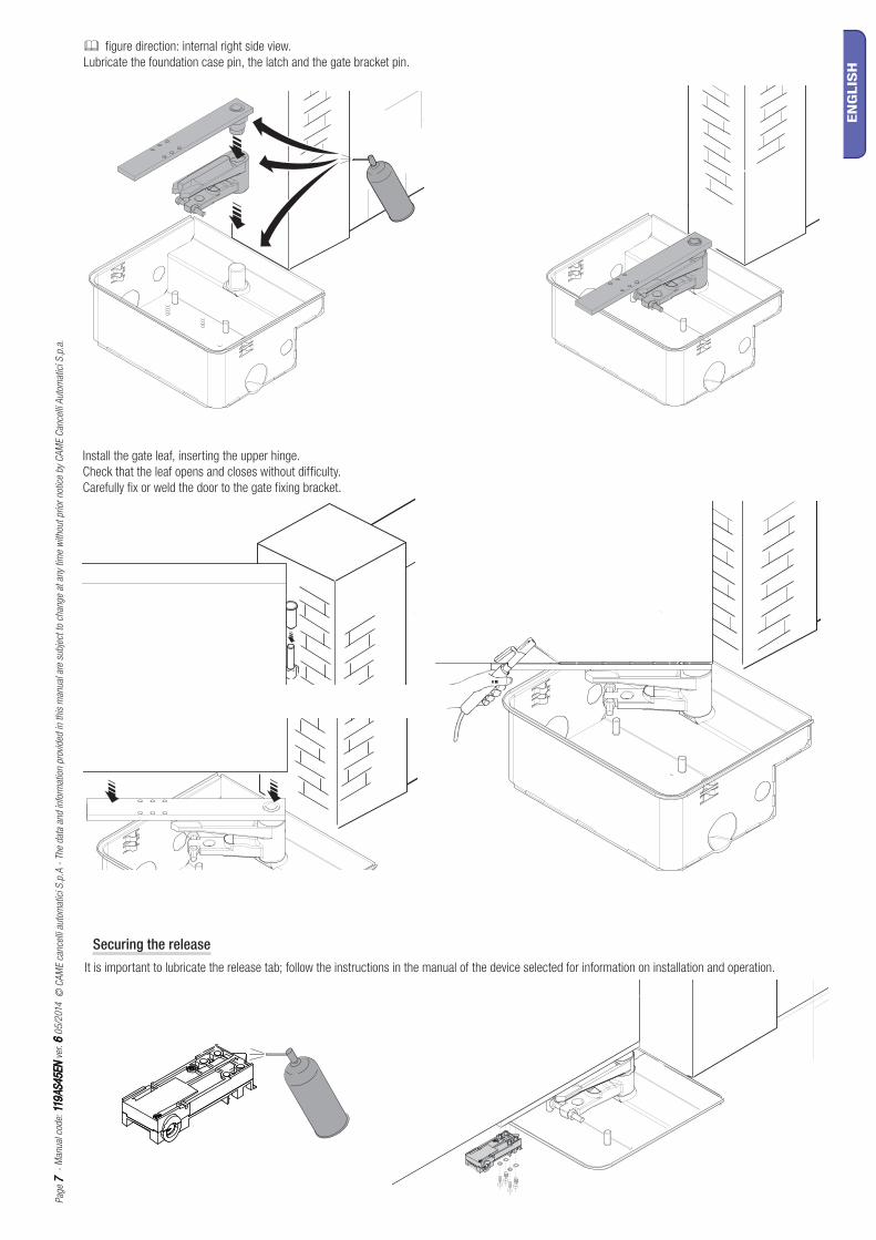
figure direction: internal right side view.
Lubricate the foundation case pin, the latch and the gate bracket pin.
Install the gate leaf, inserting the upper hinge.
Check that the leaf opens and closes without difficulty.
Carefully fix or weld the door to the gate fixing bracket.
Securing the release
It is important to lubricate the release tab; follow the instructions in the manual of the device selected for information on installation and operation.

Pag
e 88
-
Man
ual
cod
e: 1
19A
S4
5EN
119
AS4
5EN
ver
. 66
05/2
014
©
CA
ME c
ance
lli a
uto
mat
ici S
.p.A
- T
he
dat
a an
d in
form
atio
n p
rovi
ded
in t
his
man
ual
are
subje
ct t
o ch
ange
at a
ny t
ime
with
out
prior
not
ice
by
CA
ME C
ance
lli A
uto
mat
ici S
.p.a
.
ENGLISH
Open the leaf to simplify gearmotor installation and securing inside the foundation case.
Use studs and nuts (supplied).
M12 nutUNI 5588
Lubricate the transmission lever and push it into the holes of the gearmotor arm and case lever.
RIGHT SIDELEFT SIDE
Securing the gearmotor
Fit the adjusting screw into the motor arm. The direction in which the screw must be installed depends on the position of the operator.
VIEWED FROM INSIDE

3
12
1
3
2
Pag
e 99
-
Man
ual
cod
e: 1
19A
S4
5EN
119
AS4
5EN
ver
. 66
05/2
014
©
CA
ME c
ance
lli a
uto
mat
ici S
.p.A
- T
he
dat
a an
d in
form
atio
n p
rovi
ded
in t
his
man
ual
are
subje
ct t
o ch
ange
at a
ny t
ime
with
out
prior
not
ice
by
CA
ME C
ance
lli A
uto
mat
ici S
.p.a
.
ENGLISH
Determining the end run points
During opening:
- open the leaves completely (the maximum aperture is 110 °);
- loosen the screw (1) until it makes contact with the case (3);
- tighten the nut (2) to lock the screw into position.
During closing:
- close the leaves completely;
- loosen the adjusting screw (1) until it makes contact with the transmission lever (2);
- tighten the nut (3) to lock the screw into position.
For electrical connection operations follow the information in the control panel technical documents.
ELECTRICAL CONNECTIONS
Gearmotor Control panel
FROG-A ZA3N - ZM3E
FROG-AV ZA3N - ZM3E
FROG-AE ZM3E
Screw M8x25UNI 5933
FINAL OPERATIONS
Securing the cover
Rest the cover on the foundation case and fix it with the screws (supplied).

Pag
e 1010
-
Man
ual
cod
e: 1
19A
S4
5EN
119
AS4
5EN
ver
. 66
05/2
014
©
CA
ME c
ance
lli a
uto
mat
ici S
.p.A
- T
he
dat
a an
d in
form
atio
n p
rovi
ded
in t
his
man
ual
are
subje
ct t
o ch
ange
at a
ny t
ime
with
out
prior
not
ice
by
CA
ME C
ance
lli A
uto
mat
ici S
.p.a
.
ENGLISH
To relock the door, return it to its closed position.
Leaf manual release
Insert the key/lever into the release lock and turn it counter-clockwise. Open the leaf until reaching end run
MAINTENANCE
☞ Before any maintenance, disconnect power to prevent any possible dangerous situations that can be caused by accidental movement of the operator.
Lubricate the pivot points with grease whenever abnormal vibrations or squeaking occurs, as shown in the figure.
Date Notes Signature
Periodic maintenance
Periodic maintenance log to be completed by the user (every six months)

Z S
ER
IES
INSTALLATION MANUAL
ZA3N
CONTROL PANEL FOR 230V OPERATORS
English EN

Pag
. 22
-
Man
ual
cod
e: 3
19
U4
63
19
U4
6 v
er. 1
.01
.0 0
5/2
00
9 ©
CA
ME
cance
lli a
utom
atic
i s.p
.a.
- Th
e dat
a an
d in
form
atio
n re
por
ted
in t
his
inst
alla
tion
man
ual
are
susc
eptib
le t
o ch
ange
at a
ny t
ime
and
with
out
oblig
atio
n on
CA
ME
cance
lli a
utom
atic
i s.p
.a.
to n
otify
use
rs.
EN
GLIS
H
The overall power of the motors must not exceed 600W.
4 Description
2.1 Intended use
1 Legend of symbols
This symbol tells you what to say to the end-users. This symbol tells you that the sections concern safety issues. This symbol tells you what to say to the end-users.
2 Intended use and restrictions
The ZA3N control panel is designed to control the 230V ATI, FERNI, KRONO, FAST and FROG swing gate operators.
The use of this product for purposes other than those described above and installation executed in a manner other than as instructed in this technical manual are prohibited.
3 Reference standards
“IMPORTANT INSTALLATION, SAFETY INSTRUCTIONS”
“CAUTION: IMPROPER INSTALLATION MAY CAUSE SERIOUS DAMAGE, FOLLOW ALL INSTALLATION INSTRUCTIONS CAREFULLY”
“THIS MANUAL IS ONLY FOR PROFESSIONAL OR QUALIFIED INSTALLERS”
2.2 Limits to use
For its quality processes management Came Cancelli Automatici is ISO 9001:2000 certified, and for its environmental management it is ISO 14001 certified. CAME engineers and manufactures all of its products in Italy.This product complies with the following standards: see declaration of conformity.
This product is engineered and manufactured by CAME CANCELLI AUTOMATICI S.p.A. and complies with current safety regulations. Guaranteed 24 months if not tampered with.
The control panel works on 230V a.c. of power, 50/60Hz frequency.
The control devices and accessories are powered by 24V. Warning! The accessories must not exceed 20W overall.
All connections are protected by fast fuses, see table.
The board performs and controls the following functions:
- automatic closing after an opening command;
- pre-fl ashing of the fl ashing light;
- obstacle detection when gate is not running at any point;
- adjusting the motor torque on the connected automation device;
- ram blow in opening phase.
The command modes that may be defi ned are the following:
- opening/closing;
- opening/closing with maintained action;
- partial opening;
- complete stop.
Following an obstacle detection, the photocells can:
- reopening if the gate is closing;
- reclosing or partial stop if the gate is opening;
- partial stop if the gate is opening.
Expressly fi tted trimmers adjust:
- duration of theautomatic closing;
- M2 gearmotor closing delay;
- operating time.
It is also possible to connect:
- signalling lamps - gate open;
- cycle lamp;
- electric lock.
FUSES TABLE
protection: fuse for:
Control board (line) 5A-F
Control devices and accessories (control unit)
3.15A-F
TECHNICAL FEATURES
power supply 230V - 50/60Hz
max power 600W
power draw when idling 60 mAmax power of 24V accessories 20W
insulation rating
casing material ABS
casing protection rating IP54
operating temperature -20 / +55°C

(mm)
1
2
3
4 5 6 7 8 9
10
12
11
13
Pag
. 33
-
Man
ual
cod
e : 3
19
U4
63
19
U4
6 v
er. 1
.01
.0 0
5/2
00
9 ©
CA
ME
cance
lli a
utom
atic
i s.p
.a.
- Th
e dat
a an
d in
form
atio
n re
por
ted
in t
his
inst
alla
tion
man
ual
are
susc
eptib
le t
o ch
ange
at a
ny t
ime
and
with
out
oblig
atio
n on
CA
ME
cance
lli a
utom
atic
i s.p
.a.
to n
otify
use
rs.
EN
GLIS
H
4.1 Dimensions, spans and anchoring holes
4.2 Main components
Warning! Before acting on the machinery, cut off the main power supply.
* Found in the 230V FROG box. Connected them up to the black (M1 motor) cables and red (M2 motor) cables fitted on the card; when coupling with Ati, Fast, Ferni and Krono devices the cables are not used because the condensers are already connected up inside.
1 - Connection terminal boards
2 - Line fuse 5A
3 - Control unit fuse 3,15A
4 - Power up LED indicator 24V
5 - Buttons for memorising the radio code
6 - Operating time adjustment trimmer
7 - Trimmer for adjusting the automatic closure time
8 - Trimmer for adjusting the delay of M2 during closing and partial opening
9 - 10 DIP - Function selection
10 - Radio frequency card plug-in (see table)
11 - Signalling LED
12 - Torque limiter
13 - Condensers*
Blac
k
Whi
teRe
d
Oran
ge
Blue
Viol
et RedBlack
Pag
. 44
-
Man
ual
cod
e: 3
19
U4
63
19
U4
6 v
er. 1
.01
.0 0
5/2
00
9 ©
CA
ME
cance
lli a
utom
atic
i s.p
.a.
- Th
e dat
a an
d in
form
atio
n re
por
ted
in t
his
inst
alla
tion
man
ual
are
susc
eptib
le t
o ch
ange
at a
ny t
ime
and
with
out
oblig
atio
n on
CA
ME
cance
lli a
utom
atic
i s.p
.a.
to n
otify
use
rs.
EN
GLIS
H
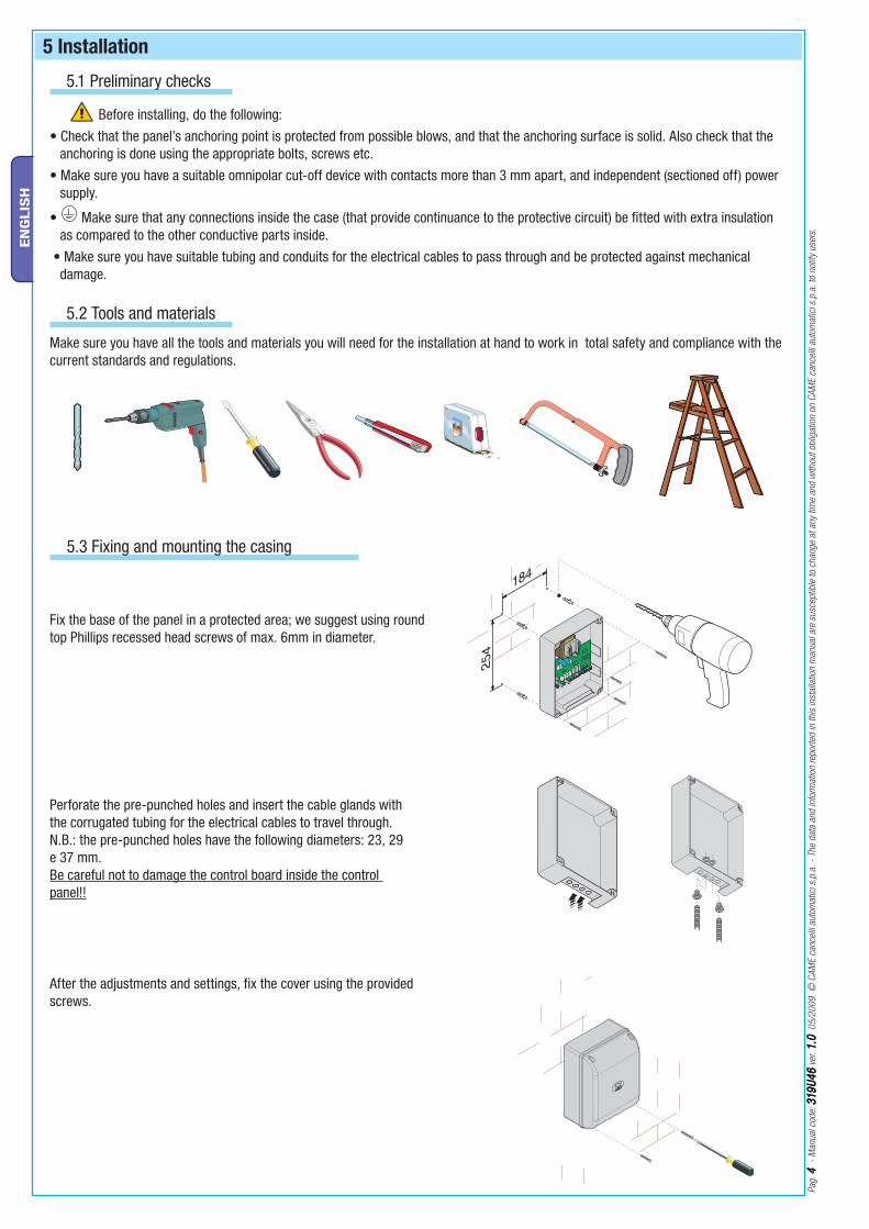
Before installing, do the following:
• Check that the panel’s anchoring point is protected from possible blows, and that the anchoring surface is solid. Also check that the anchoring is done using the appropriate bolts, screws etc.
• Make sure you have a suitable omnipolar cut-off device with contacts more than 3 mm apart, and independent (sectioned off) power supply.
• Make sure that any connections inside the case (that provide continuance to the protective circuit) be fitted with extra insulation as compared to the other conductive parts inside.
• Make sure you have suitable tubing and conduits for the electrical cables to pass through and be protected against mechanical damage.
Make sure you have all the tools and materials you will need for the installation at hand to work in total safety and compliance with the current standards and regulations.
Fix the base of the panel in a protected area; we suggest using round top Phillips recessed head screws of max. 6mm in diameter.
5.3 Fixing and mounting the casing
Perforate the pre-punched holes and insert the cable glands with the corrugated tubing for the electrical cables to travel through. N.B.: the pre-punched holes have the following diameters: 23, 29 e 37 mm.Be careful not to damage the control board inside the control panel!!
After the adjustments and settings, fix the cover using the provided screws.
5 Installation
5.1 Preliminary checks
5.2 Tools and materials

FROG
FERNI
KRONO
FROG
FERNI
KRONO
FAST
ATI
ATI
M1 M2
FAST
Pag
. 55
-
Man
ual
cod
e : 3
19
U4
63
19
U4
6 v
er. 1
.01
.0 0
5/2
00
9 ©
CA
ME
cance
lli a
utom
atic
i s.p
.a.
- Th
e dat
a an
d in
form
atio
n re
por
ted
in t
his
inst
alla
tion
man
ual
are
susc
eptib
le t
o ch
ange
at a
ny t
ime
and
with
out
oblig
atio
n on
CA
ME
cance
lli a
utom
atic
i s.p
.a.
to n
otify
use
rs.
EN
GLIS
H
6 Electrical connections
Accessories power supply
230V A.C. 50/60 Hz control panel power supply
Terminal board for 24V A.C. accessories power supply
Electrolock connection (12V - 15W max)
When using only one motor (e.g. on one leaf gates), connect it up on W X Y (M2) regardless of which side it is installed on – (fro FROG, if need be, invert connections X and Y).
Standard opening setup scheme in Came gearmotors.
Gearmotor featuring delayed action on opening (M1)
Gearmotor featuring delayed action on closing (M2)
Gearmotor
Pag
. 66
-
Man
ual
cod
e: 3
19
U4
63
19
U4
6 v
er. 1
.01
.0 0
5/2
00
9 ©
CA
ME
cance
lli a
utom
atic
i s.p
.a.
- Th
e dat
a an
d in
form
atio
n re
por
ted
in t
his
inst
alla
tion
man
ual
are
susc
eptib
le t
o ch
ange
at a
ny t
ime
and
with
out
oblig
atio
n on
CA
ME
cance
lli a
utom
atic
i s.p
.a.
to n
otify
use
rs.
EN
GLIS
H
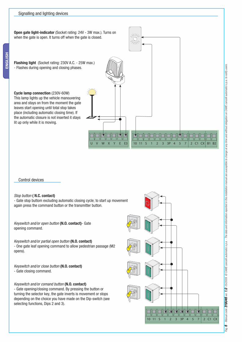
Signalling and lighting devices
Open gate light-indicator (Socket rating: 24V - 3W max.). Turns on when the gate is open. It turns off when the gate is closed.
Flashing light (Socket rating: 230V A.C. - 25W max.) - Flashes during opening and closing phases.
Cycle lamp connection (230V-60W)This lamp lights up the vehicle manouvering area and stays on from the moment the gate leaves start opening until total stop takes place (including automatic closing time). If the automatic closure is not inserted it stays lit up only while it is moving.
Control devices
Stop button ( N.C. contact) - Gate stop buttom excluding automatic closing cycle; to start up movement again press the command button or the transmitter button.
Keyswitch and/or open button (N.O. contact)- Gate opening command.
Keyswitch and/or comand button (N.O. contact) - Gate opening/closing command. By pressing the button or turning the selector key, the gate inverts is movement or stops depending on the choice you have made on the Dip-switch (see selecting functions, Dips 2 and 3).
Keyswitch and/or partial open button (N.O. contact)
- One gate leaf opening command to allow pedestrian passage (M2 opens).
Keyswitch and/or close button (N.O. contact) - Gate closing command.

TXRX
TXRX
Pag
. 77
-
Man
ual
cod
e : 3
19
U4
63
19
U4
6 v
er. 1
.01
.0 0
5/2
00
9 ©
CA
ME
cance
lli a
utom
atic
i s.p
.a.
- Th
e dat
a an
d in
form
atio
n re
por
ted
in t
his
inst
alla
tion
man
ual
are
susc
eptib
le t
o ch
ange
at a
ny t
ime
and
with
out
oblig
atio
n on
CA
ME
cance
lli a
utom
atic
i s.p
.a.
to n
otify
use
rs.
EN
GLIS
H
(N.C.) contact for «partial stop» - Input for safety devices such as photocells, sensitive edges and other EN 12978-compliant devices. Gate leaves are stopped if in motion, with consequent setup of automatic closing.Dip 8 OFF - 10 ON
(N.C.) contact of «re-closing during opening»- Input for safety devices such as photocells, sensitive edges and other EN 12978-compliant devices. During the gate leaves closing phase, opening the contact causes movement inversion until fully closed.Dip 8 OFF - 10 OFF
Safety devices
(N.C.) contact for «re-opening during closing»- Input for safety devices such as photocells, sensitive edges and other EN 12978-compliant devices. During the gate leaves closing phase, opening the contact causes movement inversion until fully opened.
(N.C.) contact for «re-opening during closing»
(N.C.) contact for «re-closing during opening»
(N.C.) contact of «partial stop»
Or
Or
DIR photocells
DOC photocells

ON
OFF
Pag
. 88
-
Man
ual
cod
e: 3
19
U4
63
19
U4
6 v
er. 1
.01
.0 0
5/2
00
9 ©
CA
ME
cance
lli a
utom
atic
i s.p
.a.
- Th
e dat
a an
d in
form
atio
n re
por
ted
in t
his
inst
alla
tion
man
ual
are
susc
eptib
le t
o ch
ange
at a
ny t
ime
and
with
out
oblig
atio
n on
CA
ME
cance
lli a
utom
atic
i s.p
.a.
to n
otify
use
rs.
EN
GLIS
H
7 Selecting functions
DIP-SWITCH 10 WAYS
8 Adjustments
1 ON Automatic closing activated (1 OFF-disactivated);
2 ON “Open-stop-close-stop” function with button (2-7) and radio control (with built-in AF card) - activated;
2 OFF “Open-close” function with button (2-7) and transmitter (with built-in AF card) - activated;
3 ON “Open only” function with transmitter (built-in AF card) - activated (3 OFF-disactivated);
4 ON Pre-Flashing during opening and closing – activated (4 OFF- disactivated);
5 ON Obstacle detection - activated (5 OFF- disactivated);
6OFF “Maintained action” (the transmitter cannot work) deactivated (6 ON - activated);
7 ON Ram blow activated; at each opening command, the gate leaves press when against the closing jamb for a second, helping to release the electro-lock connected up on terminals 11-S. It is active only if the leaves are closed and when operating time is over, or upon the 1st run after powering up the system;
8 OFF - 10 OFF Re-close during opening function (connect the safety device on 2-CX) - activated;
8 OFF - 10 ON Partial stop function (connect the safety device on 2-CX) - activated (if the devices on 2-CX are not used, set the DIP 8 in ON);
9 OFF Re-open during closing function - activated; connect the safety device on 2-C1 (if the device on 2-CX is not used, et the DIP in ON).
Trimmer T.L. = Adjusting the working time from 0” to 120”.
Trimmer T.C.A. = Adjusting the automatic closing from 1” to 120”.
Trimmer TR2M = Adjusting the M2 closing delay (min. 0”, max. 15”) and simultaneous partial opening (min. 0”, max. 30”).

ATOMO
AT01 • AT02AT04
CAME
CAMECAME
CAME
CAME
TOUCH
TCH 4024 • TCH 4048
TOP
TOP-432A • TOP-434A TOP-302A • TOP-304A
TAM
T432 • T434 • T438 TAM-432SA
CAMECAME
CAME
CAME
CAME
CAME
CAME
CAME
CAME
CAME
CAME
TWIN
TWIN-302A • TWIN-304A
TFM
T132 • T134 • T138T152 • T154 • T158
TOP
TOP-432NA • TOP-434NATOP-432S
Pag
. 99
-
Man
ual
cod
e : 3
19
U4
63
19
U4
6 v
er. 1
.01
.0 0
5/2
00
9 ©
CA
ME
cance
lli a
utom
atic
i s.p
.a.
- Th
e dat
a an
d in
form
atio
n re
por
ted
in t
his
inst
alla
tion
man
ual
are
susc
eptib
le t
o ch
ange
at a
ny t
ime
and
with
out
oblig
atio
n on
CA
ME
cance
lli a
utom
atic
i s.p
.a.
to n
otify
use
rs.
EN
GLIS
H
9 Motor torque limiter
To vary the motor torque, shift the shown faston to one of the 4 positions: 1 min., 4 max.
Transmitters
see a
ttach
ed in
struc
tions
see instructions attached to AF43SR card

TOP TAM
Pag
. 1
01
0
- M
anual
cod
e: 3
19
U4
63
19
U4
6 v
er. 1
.01
.0 0
5/2
00
9 ©
CA
ME
cance
lli a
utom
atic
i s.p
.a.
- Th
e dat
a an
d in
form
atio
n re
por
ted
in t
his
inst
alla
tion
man
ual
are
susc
eptib
le t
o ch
ange
at a
ny t
ime
and
with
out
oblig
atio
n on
CA
ME
cance
lli a
utom
atic
i s.p
.a.
to n
otify
use
rs.
EN
GLIS
H
AF card
Lock the radiofrequency card into the electronic card AFTER CUTTING OFF THE POWER SUPPLY (or after disconnecting the batteries).N.B.: The control board only recognises the radiofrequency card when the power is on.
Only for cards marked on the table:- place the jumper as shown depending on the series of transmitters used. (see diagram).
10 Activating the radio control
Connect the antenna’s RG58 cable to the apposite terminals.
Antenna
Radio frequency card
Possible output of the radio receiver’s second channel (N.O. contact). Socket rating: 5A-24V D.C.
Frequency/MhzRadio
frequency card
Transmitters
series
FM 26.995 AF130 TFM
FM 30.900 AF150 TFM
AM 26.995 AF26 TOP
AM 30.900 AF30 TOP
AM 433.92AF43S / AF43SM TAM / TOP
AF43SR ATOMO
AF43TW TWIN
AM 40.685 AF40 TOUCH

CH1
Pag
. 1111
-
Man
ual
cod
e : 3
19
U4
63
19
U4
6 v
er. 1
.01
.0 0
5/2
00
9 ©
CA
ME
cance
lli a
utom
atic
i s.p
.a.
- Th
e dat
a an
d in
form
atio
n re
por
ted
in t
his
inst
alla
tion
man
ual
are
susc
eptib
le t
o ch
ange
at a
ny t
ime
and
with
out
oblig
atio
n on
CA
ME
cance
lli a
utom
atic
i s.p
.a.
to n
otify
use
rs.
EN
GLIS
H
1) Keep the CH1 button on the electronic card pressed. The LED fl ashes. Press the transmitter button you wish to memorise. The LED will stay on to show memorisation has been successful.
2) Perform the same procedure with the CH2 button coupling it to another button on the transmitter.
CH1 = Channel for direct command to a function of the the gearmotor’s card, (“open only / “open-close-invert” or “open-stop-close-stop” command, depending on the choice made on DIP switches 2 and 3).
CH2 = Channel for direct command an accessory device connected to B1-B2.
Memorisation
Intermitting LED
AF radio frequency card
11 Phasing out and disposal
MANUFACTURER’S DECLARATION OF CONFORMITYPursuant to annex II B of the Machinery Directive 98/37/EC
CAME Cancelli Automatici S.p.A.
via Martiri della Libertà, 15 31030 Dosson di Casier - Treviso - ITALY tel (+39) 0422 4940 - fax (+39) 0422 4941 internet: www.came.it - e-mail: [email protected]
Declares under its own responsibility that the equipments for automatic garage doors and gates listed below:
ZA3N
… comply with the National Law related to the following European Directives and to the applicable parts of the following Standards.
--- DIRECTIVES ---98/37/CE - 98/79/CE MACHINERY DIRECTIVE
89/336/CEE - 92/31/CEE ELECTROMAGNETIC COMPATIBILITY DIRECTIVE
73/23/CEE - 93/68/CE LOW VOLTAGE DIRECTIVE
89/106/CEE CONSTRUCTION PRODUCTS DIRECTIVE
--- STANDARDS ---EN 13241-1 EN 12635 EN 61000-6-2 EN 12453 EN 12978 EN 61000-6-3 EN 12445 EN 60335-1
IMPORTANT WARNING!Do not use the equipment specifi ed here above,
before completing the full installation In full compliance with the Machinery Directive 98/37/EC
12 Conformity declaration
Reference code to request a true copy of the original: DDF B EN A001D
MANAGING DIRECTORMr. Andrea Menuzzo
In its premises, CAME CANCELLI AUTOMATICI S.p.A. implements an Environmental Management System certified in compliance with the UNI EN ISO 14001 standard to ensure environmental protection.Please continue our efforts to protect the environment—which CAME considers one of the cardinal elements in the development of its operational and market strategies—simply by observing brief recommendations as regards disposal:
DISPOSAL OF PACKAGINGThe packaging components (cardboard, plastic, etc.) are all classifiable as solid urban waste products and may be disposed of easily, keeping in mind recycling possibilities.Prior to disposal, it is always advisable to check specific regulations in force in the place of installation.PLEASE DISPOSE OF PROPERLY!
PRODUCT DISPOSALOur products are made up of various types of materials. Most of them (aluminium, plastics, iron, electrical wires, etc.) may be disposed of in normal garbage collection bins and can be recycled by disposing of in specific recyclable material collection bins and disposal in authorized centres. Other components (electrical boards, remote control batteries, etc.), however, may contain polluting substances. They should therefore be removed and given to qualified service companies for proper disposal.Prior to disposal, it is always advisable to check specific regulations in force in the place of disposal.PLEASE DISPOSE OF PROPERLY!