installation manual - harris manual 14221-1510-4440 rev. d, june 2016 xg-25m mobile radios ......
TRANSCRIPT

Installation Manual 14221-1510-4440
Rev. D, June 2016
XG-25M Mobile Radios Front-Mount and Remote-Mount Applications

14221-1510-4440, Rev. D
2
ACKNOWLEDGEMENT This device is made under license under one or more of the following US patents: 4,590,473; 4,636,791; 5,148,482; 5,185,796; 5,271,017; 5,377,229; 4,716,407; 4,972,460; 5,502,767; 5,146,497; 5,164,986; 5,185,795; 5,226,084; 5,247,579; 5,491,772; 5,517,511; 5,630,011; 5,649,050; 5,701,390; 5,715,365; 5,754,974; 5,826,222; 5,870,405; 6,161,089; and 6,199,037 B1. DVSI claims certain rights, including patent rights under aforementioned U.S. patents, and under other U.S. and foreign patents and patents pending. Any use of this software or technology requires a separate written license from DVSI.
CREDITS Harris, VIDA, OpenSky, MASTR, BeOn, and EDACS are registered trademarks and TECHNOLOGY TO CONNECT, INFORM AND PROTECT is a trademark of Harris Corporation. AMBE is a registered trademark and IMBE, AMBE+, and AMBE+2 are trademarks of Digital Voice Systems, Inc. Bird is a registered trademark of Bird Electronic Corporation. Microsoft and Windows are registered trademarks of Microsoft Corporation. All other brand and product names are trademarks, registered trademarks, or service marks of their respective holders.
NOTICE! The material contained herein is subject to U.S. export approval. No export or re-export is permitted without written approval from the U.S. Government. Rated: EAR99 in accordance with U.S. Dept. of Commerce regulations 15CFR774, Export Administration Regulations. Information and descriptions contained herein are the property of Harris Corporation. Such information and descriptions may not be copied or reproduced by any means, or disseminated or distributed without the express prior written permission of Harris Corporation, PSPC Business, 221 Jefferson Ridge Parkway, Lynchburg, VA 24501. The voice coding technology embodied in this product is protected by intellectual property rights including patent rights, copyrights, and trade secrets of Digital Voice Systems, Inc. The user of this technology is explicitly prohibited from attempting to decompile, reverse engineer, or disassemble the Object Code, or in any other way convert the Object Code into human-readable form. Repairs to this equipment should be made only by an authorized service technician or facility designated by the supplier. Any repairs, alterations or substitutions of recommended parts made by the user to this equipment not approved by the manufacturer could void the user's authority to operate the equipment in addition to the manufacturer's warranty.
This product conforms to the European Union WEEE Directive 2012/19/EU. Do not dispose of this product in a public landfill. Take it to a recycling center at the end of its life.
Harris products comply with the Restriction of the Use of Certain Hazardous Substances in Electrical and Electronic Equipment (RoHS) Directive.
This manual is published by Harris Corporation without any warranty. Improvements and changes to this manual necessitated by typographical errors, inaccuracies of current information, or improvements to programs and/or equipment, may be made by Harris Corporation at any time and without notice. Such changes will be incorporated into new editions of this manual. No part of this manual may be reproduced or transmitted in any form or by any means, electronic or mechanical, including photocopying and recording, for any purpose, without the express written permission of Harris Corporation. Copyright © 2013, 2014, 2016, Harris Corporation

14221-1510-4440, Rev. D
3
TABLE OF CONTENTS Section Page
1 REGULATORY AND SAFETY INFORMATION .................................................................... 7 1.1 SAFETY SYMBOL CONVENTIONS ................................................................................................. 7 1.2 REGULATORY APPROVALS ........................................................................................................... 8
1.2.1 General Information ............................................................................................................... 8 1.3 RADIO FREQUENCY INTERFERENCE ........................................................................................... 8
1.3.1 FCC Part 15 ............................................................................................................................ 8 1.3.2 Industry Canada ...................................................................................................................... 8
1.4 COMPLIANCE WITH RF EXPOSURE STANDARDS ...................................................................... 8
2 RADIO MODELS AND SPECIFICATIONS ............................................................................ 10 2.1 RADIO MODELS .............................................................................................................................. 10 2.2 SPECIFICATIONS ............................................................................................................................. 11
2.2.1 General ................................................................................................................................. 11 2.2.2 Transceiver ........................................................................................................................... 12 2.2.3 Environmental ...................................................................................................................... 14
3 INTRODUCTION ........................................................................................................................ 15 3.1 GENERAL DESCRIPTION ............................................................................................................... 15 3.2 RELATED PUBLICATIONS ............................................................................................................. 17 3.3 REPLACEMENT PARTS .................................................................................................................. 17
4 INSTALLATION PROCESS ...................................................................................................... 18 4.1 GENERAL INFORMATION ............................................................................................................. 18 4.2 RADIO PROGRAMMING ................................................................................................................. 19 4.3 PRE-INSTALLATION VEHICLE CHECK ....................................................................................... 19 4.4 PLANNING THE INSTALLATION .................................................................................................. 20
4.4.1 Mounting Location and Considerations ................................................................................ 21 4.4.2 Power Source Location and Considerations ......................................................................... 21 4.4.3 Ignition Sense Location and Considerations ........................................................................ 22 4.4.4 Ground / Return Location and Considerations ..................................................................... 23 4.4.5 Antenna Mounting Considerations ....................................................................................... 23 4.4.6 Data, Antenna, and Power Cable Routing Considerations ................................................... 23
4.5 WIRING AND CABLING REQUIREMENTS .................................................................................... 24 4.5.1 Crimping Requirements ........................................................................................................ 24 4.5.2 Splicing Requirements .......................................................................................................... 24 4.5.3 Battery Connection Requirements ........................................................................................ 24
4.6 TOOLS REQUIRED........................................................................................................................... 25 4.7 UNPACKING AND CHECKING THE EQUIPMENT ...................................................................... 26
4.7.1 Materials ............................................................................................................................... 26 4.7.2 Material Inspection ............................................................................................................... 26 4.7.3 Installation Kits .................................................................................................................... 27
5 ANTENNA INSTALLATION .................................................................................................... 31 5.1 ANTENNA MOUNTING LOCATIONS ........................................................................................... 32
5.1.1 Direct Center or Center-Rear of Rooftop ............................................................................. 32 5.1.2 Center of Trunk Lid .............................................................................................................. 32 5.1.3 Rear Deck Lid for Stand-Alone GPS Receive Antenna ....................................................... 32
5.2 RF ANTENNA INSTALLATION PROCEDURES ........................................................................... 38 5.2.1 Installing NMO Antenna Mounts AN-125001-001, -002, -003 and -004 ............................ 38 5.2.2 Installing NMO Magnetic Antenna Mounts AN-125001-007 and AN-125001-008 ............ 40 5.2.3 Installing All Other Antenna Mounts ................................................................................... 41 5.2.4 Attaching NMO Antenna Elements ...................................................................................... 41
14221-1510-4440, Rev. D
4
TABLE OF CONTENTS Section Page
5.2.5 Installing the Coax Cable and TNC RF Connector ............................................................... 41 5.3 GPS RECEIVER ANTENNA INSTALLATION PROCESS ............................................................. 44
5.3.1 General Installation Procedure .............................................................................................. 44 5.3.2 Installing a GPS Antenna Inside the Rear-Deck ................................................................... 45
6 RADIO INSTALLATION ........................................................................................................... 46 6.1 MOUNTING THE RADIO ................................................................................................................. 47
6.1.1 Mounting Bracket Installation .............................................................................................. 48 6.1.2 Inserting the Radio into the Mounting Bracket ..................................................................... 51
6.2 RADIO WIRING AND CABLING .................................................................................................... 52 6.2.1 Radio Ground (Black Wire) Connection .............................................................................. 54 6.2.2 Main Power (Red Wire and Main Fuse Holder) Connection ................................................ 54 6.2.3 Ignition Sense (White Wire) Connection .............................................................................. 56
7 REMOTE-MOUNT RADIO INSTALLATION ........................................................................ 59 7.1 MOUNTING THE REMOTE-MOUNT RADIO ................................................................................ 60
7.1.1 Application of the Remote-Control Conversion Kit ............................................................. 60 7.1.2 Installing the Remote-Mount Radio ...................................................................................... 61
7.2 CONTROL HEAD MECHANICAL INSTALLATION ..................................................................... 61 7.2.1 Selecting the Mounting Location .......................................................................................... 61 7.2.2 Installing the Mounting Bracket and Control Head .............................................................. 62
7.3 INSTALLING THE REMOTE CONTROL CABLE .......................................................................... 63
8 OPTIONS AND ACCESSORIES ............................................................................................... 66 8.1 EXTERNAL SPEAKER INSTALLATION (OPTIONAL) ................................................................ 66 8.2 MICROPHONE ATTACHMENT ...................................................................................................... 66 8.3 GPS NMEA-FORMATTED DATA CONNECTION ......................................................................... 67 8.4 MOBILE DATA CONNECTION ....................................................................................................... 68
9 OPTIONAL CABLES .................................................................................................................. 69 9.1 OPTION CABLE 14002-0174-08 ....................................................................................................... 69 9.2 SERIAL DATA CABLE CA-013671-020 .......................................................................................... 71 9.3 FRONT PANEL PROGRAMMING CABLE 14015-0200-01 ............................................................ 72 9.4 DESK MIC ADAPTER CABLE 14015-0200-02 ................................................................................ 73
10 INSTALLATION INSPECTION AND TESTS ........................................................................ 74 10.1 REQUIRED TEST EQUIPMENT ...................................................................................................... 74 10.2 INITIAL POWER-UP TEST ............................................................................................................... 75 10.3 PERFORMANCE TESTS ................................................................................................................... 76 10.4 RF POWER TESTS ............................................................................................................................ 76
10.4.1 Transmitting into a 50-Ohm Dummy Load .......................................................................... 76 10.4.2 Transmitting into the Mobile Antenna .................................................................................. 78
10.5 POST INSTALLATION INSPECTION ............................................................................................. 83
11 CARING FOR THE RADIO EQUIPMENT ............................................................................. 84 11.1 PREVENTIVE MAINTENANCE ...................................................................................................... 84 11.2 CLEANING THE RADIO EQUIPMENT ........................................................................................... 84
11.2.1 Light-Duty Cleaning Procedure ............................................................................................ 84 11.2.2 Heavy-Duty Cleaning Procedure .......................................................................................... 85
12 CUSTOMER SERVICE .............................................................................................................. 86 12.1 TECHNICAL SUPPORT .................................................................................................................... 86 12.2 TECH-LINK ....................................................................................................................................... 86

14221-1510-4440, Rev. D
5
TABLE OF CONTENTS Section Page
12.3 CUSTOMER CARE ........................................................................................................................... 86
13 INSTALLATION CHECKLIST ................................................................................................ 87
14 WARRANTY REGISTRATION ................................................................................................ 89
LIST OF FIGURES Page
Figure 3-1: Front-Mount XG-25M Mobile Radio (Front and Rear Views) ........................................................ 15 Figure 3-2: Remote-Mount XG-25M Mobile Radio (With Optional Remote-Mount Kit Applied) .................... 16 Figure 4-1: High Level Installation Process ........................................................................................................ 18 Figure 5-1: Antenna Installation Process............................................................................................................. 31 Figure 5-2: Installing a Standard ¾-Inch NMO Antenna Mount (e.g., AN-125001-001 or AN-125001-002) ... 40 Figure 5-3: Installing a Thick-Roof NMO Antenna Mount (e.g., AN-125001-003 or AN-125001-004) ........... 40 Figure 5-4: Crimping Instructions for TNC RF Connector ................................................................................. 42 Figure 5-5: Cutting Charts for Antenna Element AN-225006-001 ..................................................................... 43 Figure 6-1: Front-Mount Equipment Installation Process ................................................................................... 46 Figure 6-2: XG-25M Front-Mount Radio Dimensions (less Bracket and Cables) .............................................. 48 Figure 6-3: Mounting Bracket Kit 14015-0201-01 ............................................................................................. 50 Figure 6-4: Mounting Bracket 14015-0201-02 Dimensions (Radio Not Shown) ............................................... 51 Figure 6-5: Wiring Diagram for Front-Mount Installations ................................................................................. 53 Figure 7-1: Remote-Mount Installation Process .................................................................................................. 59 Figure 7-2: Control Head Mounting Bracket (shown positioned below head) .................................................... 62 Figure 7-3: D-Shaped Connectors of Remote Control Cable .............................................................................. 64 Figure 7-4: Left Side/Right Side Remote Control Cable Orientation .................................................................. 65 Figure 9-1: Option Cable 14002-0174-08 ........................................................................................................... 69 Figure 9-2: Serial Data Cable CA-013671-020 ................................................................................................... 71 Figure 9-3: Front Panel Programming Cable 14015-0200-01 ............................................................................. 72 Figure 9-4: Desk Mic Adapter Cable 14015-0200-02 ......................................................................................... 73 Figure 10-1: Wattmeter Connections for Antenna System Tests ........................................................................ 77
(Continued)

14221-1510-4440, Rev. D
6
LIST OF TABLES Page
Table 2-1: XG-25M Mobile Radio Catalog and Part Numbers ........................................................................... 10 Table 2-2: XG-25M Mobile Radio Environmental Specifications ...................................................................... 14 Table 4-1: Installation Kit DM-ZN9X ................................................................................................................. 27 Table 4-2: CH-25 Remote-Control Conversion Kit DM-ZN9Z (Kit 14015-0203-28 with Manual) ................... 28 Table 4-3: Antenna Options for XG-25M Mobile Radios ................................................................................... 29 Table 4-4: Additional Options and Accessories for XG-25M Mobile Radios ..................................................... 30 Table 5-1: Recommended UHF Antenna Mounting Locations with Antenna Part Numbers .............................. 33 Table 5-2: Recommended VHF Antenna Mounting Locations with Antenna Part Numbers .............................. 35 Table 5-3: Recommended 700/800 MHz Antenna Mounting Locations with Antenna Part Numbers ............... 36 Table 10-1: Test Equipment Required for Performance Tests ............................................................................. 74 Table 10-2: Transmit Power Ranges with Radio Maximum Power Levels ......................................................... 78 Table 10-3: Example Measured Forward Power Levels to Reflected Power Levels for a 1.5:1 VSWR ............. 80 Table 10-4: Antenna Mounts’ Cable RF Loss (in dB of Loss per Foot) .............................................................. 81
MANUAL REVISION HISTORY
REV. DATE REASON FOR CHANGE
A Oct/13 Added CH-25 Remote-Control Conversion Kit and the respective remote-mount vehicle installation instructions. Revised Radio Programming section and information on Front Panel Programming Cable.
B Aug/14 Added 378 - 470 MHz UHF radio and UHF antennas. Revised Microphone Attachment, Optional Cables, and cleaning procedures sections.
C Oct/14 Added EU/RF and WEEE directive information.
D Jun/16 Provided improvements to Sections 4, 6, & 7. Added flow charts, wiring diagrams, post inspection instructions and installation checklist.
Harris Corporation, Public Safety and Professional Communications (PSPC) Business, continually evaluates its technical publications for completeness, technical accuracy, and organization. You can assist in this process by submitting your comments and suggestions to the following: Harris Corporation fax your comments to: 1-434-455-6851 PSPC Business or Technical Publications e-mail us at: [email protected] 221 Jefferson Ridge Parkway Lynchburg, VA 24501

14221-1510-4440, Rev. D
7
1 REGULATORY AND SAFETY INFORMATION 1.1 SAFETY SYMBOL CONVENTIONS
The following conventions are used in this manual to alert the user to general safety precautions that must be observed during all phases of operation, installation, service, and repair of this product. Failure to comply with these precautions or with specific warnings elsewhere violates safety standards of design, manufacture, and intended use of the product. Harris Corporation assumes no liability for the customer's failure to comply with these standards.
The WARNING symbol calls attention to a procedure, practice, or the like, which, if not correctly performed or adhered to, could result in personal injury. Do not proceed beyond a WARNING symbol until the conditions identified are fully understood or met.
The CAUTION symbol calls attention to an operating procedure, practice, or the like, which, if not performed correctly or adhered to, could result in damage to the equipment or severely degrade equipment performance.
The NOTE symbol calls attention to supplemental information, which may improve system performance or clarify a process or procedure.
The electrical hazard symbol is a WARNING indicating there may be an electrical shock hazard present.

14221-1510-4440, Rev. D
8
1.2 REGULATORY APPROVALS
1.2.1 General Information FCC Type Acceptance
VHF Radio: OWDTR-0075-E
UHF Radio: OWDTR-0077-E
700/800 MHz Radio: OWDTR-0076-E
VHF Radio: Part 15, Part 22, Part 80 and Part 90
UHF Radio: Part 15 and Part 90
700/800 MHz Radio: Part 15 and Part 90
Industry Canada Certification
VHF Radio: 3636B-0075
UHF Radio: 3636B-0077
700/800 MHz Radio: 3636B-0076
Applicable Industry Canada Rules: RSS-119
1.3 RADIO FREQUENCY INTERFERENCE
1.3.1 FCC Part 15
This device complies with Part 15 of the FCC Rules. Operation is subject to the following two conditions:
1. This device may not cause harmful interference; and,
2. This device must accept any interference received, including interference that may cause undesired operation.
1.3.2 Industry Canada
This device complies with Industry Canada license-exempt RSS standard(s). Operation is subject to the following two conditions: (1) this device may not cause interference, and (2) this device must accept any interference, including interference that may cause undesired operation of the device.
Le présent appareil est conforme aux CNR d'Industrie Canada applicables aux appareils radio exempts de licence. L'exploitation est autorisée aux deux conditions suivantes : (1) l'appareil ne doit pas produire de brouillage, et (2) l'utilisateur de l'appareil doit accepter tout brouillage radioélectrique subi, même si le brouillage est susceptible d'en compromettre le fonctionnement.
1.4 COMPLIANCE WITH RF EXPOSURE STANDARDS
The XG-25M two-way mobile radio is designed and tested to comply with a number of national and international standards and guidelines regarding human exposure to RF electromagnetic energy. This radio complies with the IEEE and ICNIRP exposure limits for occupational/controlled RF exposure environment at duty-cycle times of up to 50% (50% transmit, 50% receive), and it is authorized by the

14221-1510-4440, Rev. D
9
FCC for occupational use. In terms of measuring RF energy for compliance with the FCC exposure guidelines, the radio’s antenna radiates measurable RF energy only while it is transmitting (talking), not when it is receiving (listening), or in a standby mode.
The XG-25M two-way mobile radio complies with the following RF energy exposure standards and guidelines:
• United States Federal Communications Commission (FCC), Code of Federal Regulations; 47 CFR § 2 sub-part J.
• American National Standards Institute (ANSI)/Institute of Electrical and Electronic Engineers (IEEE) C95.1-2005.
• Institute of Electrical and Electronic Engineers (IEEE) C95.1-2005.
• IC Standard RSS-102, Issue 5, 2015: Spectrum Management and Telecommunications Radio Standards Specification. Radiofrequency Exposure Compliance of Radiocommunication Apparatus (All Frequency Bands).
• DIRECTIVE 2004/40/EC OF THE EUROPEAN PARLIAMENT AND OF THE COUNCIL of 29 April 2004 on the minimum health and safety requirements regarding the exposure of workers to the risks arising from physical agents (electromagnetic fields) and amended by:
• Directive 2007/30/EC of the European Parliament and of the Council of 20 June 2007
• Directive 2008/46/EC of the European Parliament and of the Council of 23 April 2008
• Regulation (EC) No 1137/2008 of the European Parliament and of the Council of 22 October 2008
• Directive 2012/11/EU of the European Parliament and of the Council of 19 April 2012
Please refer to the Safety Manual and Operator’s Manual for a list of recommended minimum safe lateral distances for a controlled environment and for unaware bystanders in an uncontrolled environment. Distances are relative to transmitting antennas (i.e., monopoles over a ground plane, or dipoles) at rated radio power for mobile radios installed in a vehicle. Transmit only when unaware bystanders are at least the uncontrolled recommended minimum safe lateral distance away from the transmitting antenna.

14221-1510-4440, Rev. D
10
2 RADIO MODELS AND SPECIFICATIONS 2.1 RADIO MODELS
Table 2-1: XG-25M Mobile Radio Catalog and Part Numbers
CATALOG NUMBER*
RADIO PART NUMBER DESCRIPTION
DM-MV1B 14015-0010-01 XG-25M VHF (136 to 174 MHz) 50-Watt Radio w/ CH-25 Control Head
DM-MU1B 14015-0030-01 XG-25M UHF (378 to 470 MHz) 50-Watt Radio w/ CH-25 Control Head
DM-M78B 14015-0020-01 XG-25M Dual-Band 700/800 MHz 35-Watt Radio w/ CH-25 Control Head
* In addition to the radio and control head, each catalog package also contains a Product Safety Manual and a Quick Guide.

14221-1510-4440, Rev. D
11
2.2 SPECIFICATIONS1
2.2.1 General Dimensions (Height x Width x Depth):
Front-Mount Radio with CH-252: 2.8 x 7.24 x 7.9 inches (7.1 x 18.4 x 20 centimeters)
Remote-Mount Radio3: 2.8 x 7.24 x 7.2 inches (7.1 x 18.4 x 18.3 centimeters)
CH-25 Control Head and Cable4: 2.8 x 7.24 x 2.8 inches (7.1 x 18.4 x 7.1 centimeters)
Weight:
Front-Mount Radio with CH-25: 5.91 pounds (2.68 kilograms); without bracket
Remote-Mount Radio: 3.70 pounds (1.68 kilograms); without bracket
CH-25 Control Head and Cable: 3.62 pounds (1.64 kilograms); includes remote control cable; does not include bracket
Operating Ambient Temperature Range: -22 to +140° Fahrenheit (-30 to +60° Celsius)
Storage Temperature Range: -40 to +176° Fahrenheit (-40 to +80° Celsius)
Relative Humidity: 90% @ 122°F (+50°C)
Altitude:
Operating: 15,000 feet (4,572 meters) maximum
Transport/Storage: 50,000 feet (15,240 meters) maximum
DC Supply Voltage Operating Ranges:
For Full Performance: +13.6 Vdc ±10% (Normal range per TIA-603)
Overall Operating Range: +13.6 Vdc ±20%
Power Transients/Surge: Per ISO7637-2
DC Supply Current Requirements:
Transmit:
VHF Radio at 50 Watts: 15 amps maximum, 11 amps typical
UHF Radio at 50 Watts: 15 amps maximum, 13 amps typical
700/800 MHz Radio at 35 Watts: 15 amps maximum, 12 amps typical
Receive:
Standby with Speaker Muted: 1.4 amps maximum
With 15-Watt Ext. Spkr. Output Power: 4.0 amps maximum
Quiescent/Off Current: 2 milliamps maximum
1 These specifications are primarily intended for the use of the installation technician. See the appropriate Specifications
Sheet for the complete specifications. 2 Includes knobs but not space required for mounting bracket and cables at rear of radio. 3 Does not include space required for mounting bracket and cables at rear of radio. 4 Does not include space required for mounting bracket and cables at rear of head.

14221-1510-4440, Rev. D
12
2.2.2 Transceiver Frequency Ranges:
VHF Radio: 136 to 174 MHz (transmit and receive)
UHF Radio: 378 to 470 MHz (transmit and receive)
700/800 MHz Radio:
700 MHz Band Receive: 764 to 776 MHz
700 MHz Band Transmit: 764 to 776 MHz and 794 to 805 MHz
800 MHz Band Receive: 851 to 870 MHz
800 MHz Band Transmit: 806 to 825 MHz and 851 to 870 MHz
Transmit Power:
VHF Radio: 10 to 50 watts (programmable range)
UHF Radio: 5 to 50 watts (programmable range)
700/800 MHz Radio, 700 MHz Band 0.3 to 35 watts (programmable range); see NOTE below.
700/800 MHz Radio, 800 MHz Band 1 to 35 watts (programmable range)
The 700/800 MHz XG-25M radio is aligned for a maximum transmit power of 35 watts across the entire 700/800 MHz frequency band. However, for FCC licensed systems, verify the radio’s 700 MHz channels are limited to 30 Watts or per license requirements via the radio’s personality programming.
The UHF XG-25M radio is aligned for a maximum transmit power of 50 watts across its entire 378 - 470 MHz operating band. However, for equipment operating in accordance with FCC 47CFR80 rules (i.e., Maritime Services), it is the responsibility of the licensee to ensure the radio is installed and aligned per license requirements.
Antenna Port Impedance: 50 ohms
Channel Spacing: 12.5 kHz or 25 kHz (mode dependent)5
Voice and Data Communications Modes: Half-Duplex
Frequency Stability: VHF Radio: ±2 ppm (-30 to + 60°C, +25°C Ref) UHF and 700/800 MHz Radios: ±1.5 ppm (-30 to + 60°C, +25°C Ref)
Receiver Sensitivity: VHF and UHF Radios: Analog Mode: better than -119 dBm (0.25 µV) at 12 dBm SINAD P25 Mode (TIA-102 Method): better than -116 dBm (0.35 µV) at 5% static BER
5 VHF and UHF radio is compliant with applicable FCC narrowbanding mandate below 512 MHz.

14221-1510-4440, Rev. D
13
700/800 MHz Radio: Analog Mode, 700 MHz Band: better than -116 dBm (0.35 µV) at 12 dBm SINAD Analog Mode, 800 MHz Band: better than -119 dBm (0.25 µV) at 12 dBm SINAD P25 Mode (TIA-102 Method): better than -116 dBm (0.35 µV) at 5% static BER
Receiver Intermodulation Rejection: >77 dB typical
Audio Frequency Response: 300 to 3000 Hz (transmit and receive)
Microphone Input Sensitivity: 82 ±28 mV rms (typical)
Microphone Audio Frequency Response: ±0.5 dB from 100 Hz to 3000 Hz
Microphone Connector: 12-pin locking connector located on front panel
Speaker Audio Output Power Internal Speaker: 3 watts RMS (8-ohm speaker) External Speaker (Optional): 15 watts RMS into a 4-ohm speaker
Speaker Audio Output Distortion: Internal Speaker: < 3% at 3 watts RMS audio output External Speaker (Optional): < 3% at 15 watts RMS audio output
Mic A-D and Speaker D-A Audio Conversion CODEC Audio Sampling Rate: 8 kHz CODEC Algorithm (Vocoding Method): Sigma-Delta (∑∆)
Voice-Coding Method: OTP Mode: Advanced Multi-Band Excitation (AMBE®) EDACS, ProVoice, & P25 Phase I Modes: Improved Multi-Band Excitation (IMBE®) P25 Phase II Mode: Advanced Multi-Band Excitation Plus 2 (AMBE+2)
Data Rate OTP Mode: 19.2 kbps (9600 symbols per second) EDACS and ProVoice Modes: 9.6 kbps P25 Mode: 4800 symbols/second

14221-1510-4440, Rev. D
14
2.2.3 Environmental
The XG-25M mobile radio and the CH-25 control head meet the following environmental specifications:
Table 2-2: XG-25M Mobile Radio Environmental Specifications
DESCRIPTION APPLICABLE STANDARD
METHOD OR SECTION
PROCEDURE
Low Pressure MIL-STD-810G 500.5 I & II
High Temperature +60°C Operating +80°C Storage
MIL-STD-810G 501.5 I & II
Low Temperature -30°C Operating -57ºC Storage
MIL-STD-810G 502.5 I & II
Temperature Shock -30°C to +60°C
MIL-STD-810G 503.5 I-B
Solar Radiation (240 Hours)
MIL-STD-810G 505.5 II
Blowing Rain MIL-STD-810G 506.5 I
Humidity MIL-STD-810G 507.5 II
Salt Fog MIL-STD-810G 509.5 I
Blowing Dust MIL-STD-810G 510.5 I
Basic Transportation Vibration
MIL-STD-810G 514.6 I, CAT 4
Min Integrity Vibration MIL-STD-810G 514.6 I, CAT 24
Functional/Basic Shock MIL-STD-810G 516.6 I
Transit Drop MIL-STD-810G 516.6 IV
Vibration Stability U.S.F.S. Par. 2.15 N/A
IP-54 IEC 60529 N/A

14221-1510-4440, Rev. D
15
3 INTRODUCTION This manual contains installation procedures for the XG-25M mobile radios and related options and accessories. Procedures cover the mounting and cabling of the radio equipment, as well as basic in-vehicle radio tests.
3.1 GENERAL DESCRIPTION
The XG-25M mobile radio is a high-performance digital mobile radio. It can operate in Project 25 (P25) trunked (Phase 1 or 2), P25 conventional, EDACS®/ProVoice™ trunked, and analog conventional modes. The radio is available in three (3) different RF bands:
• 136 to 174 MHz 50-Watt VHF radio;
• 378 to 470 MHz 50-Watt UHF radio; and,
• 700/800 MHz 35-Watt dual-band radio.
The XG-25M is typically installed in a front-mount configuration; see Figure 3-1 below. However, an optional field-applied remote-mount kit is available that supports a remote-mount radio configuration. I a remote-mount configuration, the control head connects to the radio using remote interface hardware and a 30-foot cable included in the kit as shown in Figure 3-2.
Figure 3-1: Front-Mount XG-25M Mobile Radio (Front and Rear Views)
14221-1510-4440, Rev. D
16
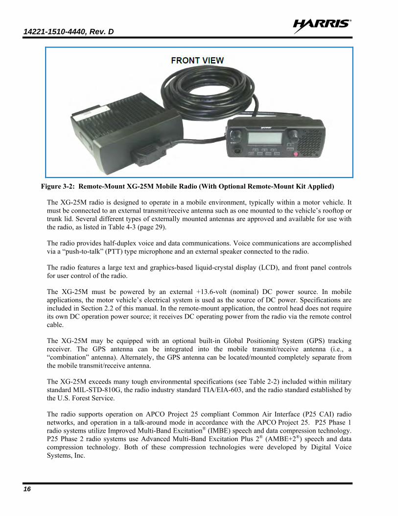
Figure 3-2: Remote-Mount XG-25M Mobile Radio (With Optional Remote-Mount Kit Applied)
The XG-25M radio is designed to operate in a mobile environment, typically within a motor vehicle. It must be connected to an external transmit/receive antenna such as one mounted to the vehicle’s rooftop or trunk lid. Several different types of externally mounted antennas are approved and available for use with the radio, as listed in Table 4-3 (page 29).
The radio provides half-duplex voice and data communications. Voice communications are accomplished via a “push-to-talk” (PTT) type microphone and an external speaker connected to the radio.
The radio features a large text and graphics-based liquid-crystal display (LCD), and front panel controls for user control of the radio.
The XG-25M must be powered by an external +13.6-volt (nominal) DC power source. In mobile applications, the motor vehicle’s electrical system is used as the source of DC power. Specifications are included in Section 2.2 of this manual. In the remote-mount application, the control head does not require its own DC operation power source; it receives DC operating power from the radio via the remote control cable.
The XG-25M may be equipped with an optional built-in Global Positioning System (GPS) tracking receiver. The GPS antenna can be integrated into the mobile transmit/receive antenna (i.e., a “combination” antenna). Alternately, the GPS antenna can be located/mounted completely separate from the mobile transmit/receive antenna.
The XG-25M exceeds many tough environmental specifications (see Table 2-2) included within military standard MIL-STD-810G, the radio industry standard TIA/EIA-603, and the radio standard established by the U.S. Forest Service.
The radio supports operation on APCO Project 25 compliant Common Air Interface (P25 CAI) radio networks, and operation in a talk-around mode in accordance with the APCO Project 25. P25 Phase 1 radio systems utilize Improved Multi-Band Excitation® (IMBE) speech and data compression technology. P25 Phase 2 radio systems use Advanced Multi-Band Excitation Plus 2® (AMBE+2®) speech and data compression technology. Both of these compression technologies were developed by Digital Voice Systems, Inc.

14221-1510-4440, Rev. D
17
3.2 RELATED PUBLICATIONS
The following publications contain additional information about the XG-25M mobile radio: • Quick Guide: 14221-1510-1000
• Operator’s Manual: 14221-1510-2000
• Product Safety Manual: 14221-1510-4000
• CH-25 Remote-Control Conversion Kit Product Manual: 14221-1510-4450
• Maintenance Manual, VHF: 14221-1510-5000
• Maintenance Manual, UHF: 14221-1510-5400
• Maintenance Manual, 700/800 MHz: 14221-1510-5020
The Product Safety Manual and a Quick Guide (for radio operators) are included with each mobile radio equipment package when it ships from the factory. The Quick Guide and the Operator’s Manual are available at https://www.harris.com/solution/xg-25m-two-way-mobile-radio without a login. Obtaining a Maintenance Manual or this Installation Manual from that web site requires an Information Center log-in, then browsing to Tech Link’s Technical Manual Library.
3.3 REPLACEMENT PARTS
Replacement parts can be ordered via our Customer Care center. To order replacement parts, call, fax or e-mail:
United States:
• Phone Number: 1-800-368-3277
• Fax Number: 1-321-409-4393
• E-mail: [email protected]
International:
• Phone Number: 1-434-455-6403
• Fax Number: 1-321-409-4394
• E-mail: [email protected]

14221-1510-4440, Rev. D
18
4 INSTALLATION PROCESS 4.1 GENERAL INFORMATION
Before starting, plan the installation carefully so it will meet the following requirements:
• The installation must be safe for the operator and passengers within the vehicle.
• The installation allows for convenient access by the operator, as applicable (i.e., the control head or hand-held controller).
• The mobile radio is mounted in a location assuring the vehicle occupants’ safety and out of the way of passengers and auto mechanics.
• The equipment is installed away from the airbag deployment areas.
• The equipment is protected from water damage.
• The installation is neat and allows easy service access.
Before the starting the installation, it is imperative to discuss with the customer the exact location in the vehicle where equipment is going to be installed. This will prevent hours of rework and reinstallation, and will build customer satisfaction.
Figure 4-1 shows the high level process for performing mobile radio installations.
Figure 4-1: High Level Installation Process
NOTE

14221-1510-4440, Rev. D
19
4.2 RADIO PROGRAMMING
Unless otherwise stated, all radio installation and test procedures presented in this manual assume the radio has been programmed by radio network administration personnel before it is delivered to radio installation personnel. Programming instructions are beyond the scope of this manual.
Radio Personality Manager (RPM) software application TQS3385 (part number SK-104768-001) is used to program the XG-25M mobile radio for trunked radio systems. RPM can also be used to program the radio for analog conventional and P25 conventional operations. For additional information, refer to RPM’s built-in online help and/or RPM Software Release Notes, publication number MS-012550-001.
RPM can also be used to flash new operating software (i.e., firmware) into an XG-25M mobile radio. Refer to the radio’s maintenance manual for additional information.
RPM Release R9A or later is required to program the VHF radio.
RPM Release R11A or later is required to program the UHF radio.
RPM Release R10A or later is required to program the 700/800 MHz radio.
The XG-25M mobile radio can be programmed via a serial port at the 44-pin connector on the radio’s rear panel or via a serial port at the front panel microphone connector. Programming instructions are beyond the scope of this manual.
For programming via the rear panel serial port, Option Cable 14002-0174-08 must be used to connect the radio’s rear panel 44-pin connector to a service computer running the RPM application. A 9-pin DB-style connector of the Option Cable is used for connection to the computer’s serial port.
For programming via the mic connector serial port, Front Panel Programming Cable 14015-0200-01 must be used to connect the radio’s mic connector to a service computer running the RPM application. The 9-pin DB-style connector of the Option Cable is used for connection to the computer’s serial port.
Programming via the mic connector’s serial port using Front Panel Programming Cable has certain limitations! Refer to Section 9.3 on page 72 for additional information.
4.3 PRE-INSTALLATION VEHICLE CHECK
Performing a vehicle pre-installation equipment check will provide a vehicle operation baseline prior to installing Harris mobile equipment. This pre-check can be documented using the sample Installation Checklist provided later in this manual.
At times the performance of the pre-check may require a certified operator.
The items to be checked are detailed on the Installation Checklist. All items are to be checked, and the results indicated on the checklist, or indicated as “n/a” or “not applicable” if the vehicle does not have it. Record clearly any items that are non-functional, and any servicing that must be completed before the install can begin. Bring these to attention of the authorized customer representative.
NOTE

14221-1510-4440, Rev. D
20
4.4 PLANNING THE INSTALLATION
Carefully plan the mounting locations of all components (radio, control head/hand-held controller, antenna, and cables) and determine the routes for all wiring and cables.
Before installing the mobile radio equipment, check the vehicle manufacturer’s user manual for warnings or recommendations.
Harris recommends the buyer use only an authorized representative to install and service this product. The warranties provided to the buyer under the terms of sale shall be null and void if this product is installed or serviced improperly, and Harris will have no further obligation to the buyer for any damage caused to the product or to any person or personal property.
The radio uses a heat sink on the radio and natural convection as its method of cooling. Cooling occurs when the ambient temperature of the air surrounding the radio is lower than the radio’s heat sink temperature, and air flows freely around the heat sink. The design of the heat sink is thermally sufficient to dissipate the maximum amount of heat generated by the radio as long as the ambient air temperature around it remains below the maximum specified limit of +140° Fahrenheit (+60° Celsius).
In order to ensure proper operation, the following guidelines must be followed:
• Operate the radio within its specified temperature limits.
• Do not place items above, against, or around the radio.
• Do not mount the radio upside down. Mounting the radio upside down will cause its heat sink to not operate as designed and could cause the radio to overheat in certain environments reducing the radio’s performance.
• When operating, keep the radio out of direct sunlight and away from heat sources.
• Installations behind a door or cover or in a protective enclosure must provide adequate free-air ventilation or cooling to the radio.
The radio will automatically reduce its transmit RF output power when its ambient temperature exceeds approximately +140° Fahrenheit (+60° Celsius).
Use only Harris supplied mounting brackets, hardware, and interconnect cabling when installing the mobile radio, control heads, and accessories (speakers, microphones, etc.).
Failure to use approved parts and accessories may cause product issues, such as; degraded radio performance, corrosion from dissimilar metals, or substandard equipment installations.
Detailed installation procedures and testing mobile radio products are given in the applicable sections. Items to consider during the planning phase are listed in the following subsections.

14221-1510-4440, Rev. D
21
4.4.1 Mounting Location and Considerations • The radio’s mounting location should be chosen to provide protection of the cables and connectors on
the rear of the unit.
• Consider the location of the fuel tank and drive shaft. Mounting screws may pierce the tank or damage the shaft.
• Connectors on the rear panel of the radio are not watertight. Ensure waterproof covers are installed on unused connectors.
• Care should be taken to avoid installing where condensation from vehicle air-conditioners or leaking windows may spill onto the radio.
• Orientation of the radio should allow access to the connectors for future testing and programming.
• The control head should be positioned so the driver / operator can have easy view and access to the display and controls.
• The location of the radio should be chosen so as not to interfere with driver and passenger movement or inhibit the movement or adjustment of vehicle seats.
• The radio and any associated equipment should be located out of the vehicle’s airbag zone.
• A microphone hang-up clip is provided as part of the installation kit. This should be located to provide convenient access to the driver / operator, yet not interfere with any vehicle controls.
• Installations in certain harsh environments may require using best practices to protect the equipment, including the following:
Positioning the equipment to avoid direct impact from water and hose-down, snow, dust, smoke, gases, road debris, oils, chemicals and corrosive agents.
Installation behind a door or cover in a protective enclosure (must provide adequate airflow and cooling).
Use of splash guards, shields, or covers, to protect against direct impacts.
Refer to the Caring for The Radio Equipment section on page 84 for additional information.
4.4.2 Power Source Location and Considerations • Some vehicles operate on 24 VDC; so it’s important that the location chosen is a 12 VDC source. If a
12 VDC source is not available, a converter will need to be installed.
• Ensure that the location chosen is a main power source and will allow the addition of added terminals.
• If an auxiliary fuse block is going to be used, ensure that the location chosen for the block will guard against possible short circuits.
• Some vehicles, trucks in particular, will have studs on the firewall that may be used to pass power without the need for a through hole. These can be used only if verified that they are not used to connect data cables or wires.

14221-1510-4440, Rev. D
22
4.4.3 Ignition Sense Location and Considerations
Chose an ignition sense that will not interfere with the safety related systems of the vehicle.
The ignition sense wire (white wire) connection determines how or when power is applied to the mobile radio. The white wire is sometimes referred to as the “white ignition switch wire” or the “ignition sense input wire.”
There are three configurations for using the ignition sense wire to power the mobile radio:
• The mobile radio is powered on and off with the vehicle ignition. See Section 4.4.3.1.
• The mobile radio is powered on and off with a master switch or timer. See Section 4.4.3.2.
• The mobile radio is hot-wired, power is always applied to the mobile radio. See Section 4.4.3.3.
Regardless of the configuration, the radio’s main DC power input (red A+ wire) must be connected through an in-line fuse to unswitched vehicle DC power.
Any DC input power provided to the radio must be between +10.8 to +16.6 Vdc.
If the vehicle experiences AC noise or DC spikes exceeding 18 volts, then DC conditioning will be required before any DC power is connected to the radio. This includes conditioning for both the radio’s main DC power input lead and for its switched ignition sense power input.
DC conditioning can be accomplished by a noise filter or DC isolation equipment such as Harris part number FL-018314-001 or FL-018314-002, or similar units with equal specifications. Also, a fuse must be placed in-line before any noise filter. Contact the Harris Technical Assistance Center for additional information.
4.4.3.1 Power On/Off Using Vehicle Ignition
To power the mobile radio on and off with the vehicle’s ignition, the sense wire needs to be connected to one of switched power sources, typically known as “Accessory” power.
In this configuration, the white wire connects to a switched power source, typically identified as “Accessory” power, that switches on and off with the vehicle’s ignition switch/key. This source must switch on (up to positive (+) battery voltage potential) when the vehicle’s ignition switch/key turns on, and it must switch off (to near zero volts) when the ignition switch/key turns off. The required fuse rating is 3 amperes. When using this configuration, the radio’s on/off/volume control must be left in the on position for automatic power-up/down to function properly.
The accessory source is normally found in the vehicle’s interior fuse block. The source chosen should have nothing to do with the vehicle’s safety systems. Refer to the vehicle’s owner’s manual when choosing an appropriate accessory source.
4.4.3.2 Power On/Off Using Master Power Switch or Timer
In this configuration, the radio remains on even when the ignition key is removed from the vehicle and a separate on/off is controlled by a master switch or an in-line timer. Typically the 12 VDC source is the same as the radio’s power source.

14221-1510-4440, Rev. D
23
• Master switch install - This allows the radio to remain powered on after the ignition is turned off. It is important to note that the vehicle’s battery will go dead if the switch is not powered off.
• Timer circuit install - This allows the radio to remain powered on for a set period of time. This configuration can also drain the battery if it is weak or old.
The required fuse rating is 3 amperes. When using this configuration, the radio’s on/off/volume control must be left in the on position for automatic power-up/down to function properly.
4.4.3.3 Power On/Off Using Mobile Radio On/Off/Volume Control Knob
In this configuration, the radio’s on/off power is controlled using its on/off/volume control. This enables the radio to remain on even when the ignition key is removed from the vehicle and a separate on/off switch is not desired and/or acceptable. The ignition sense line is connected directly to an unswitched 12 VDC power source via a 3 amp in-line fuse. It is important to note that the vehicle’s battery will go dead if the radio’s switch is allowed to remain on and the vehicle is not running.
4.4.4 Ground / Return Location and Considerations • Care should be taken to ensure the location chosen is truly to vehicle ground.
• The location chosen should not be in an area that is prone to moisture retention.
• Ensure that the location will protect the terminal from being bumped and allow the connection to loosen.
• The location must allow a through bolt with a nut and lock washer or be at a factory ground.
• Chose a location that will allow the ground lead to be as short as possible.
4.4.5 Antenna Mounting Considerations • Antenna location must be chosen based on the installation instructions provided in this manual and in
consideration of other items installed on the vehicle’s roof.
• There must be at least a 12" separation between the antenna and any other roof mounted equipment.
• If the antenna being used requires a ground plane, the location chosen must provide an acceptable ground.
• If mirror mounts are being used, ensure the mirrors are properly installed.
4.4.6 Data, Antenna, and Power Cable Routing Considerations • Cables should not be routed under vehicle carpeting where the feet of occupants rest.
• Plan the cable runs so as to protect the cables from chafing, crushing, moisture, or overheating.
• Routing under the dash should not interfere with, or pass through, the steering column, brake pedal, clutch pedal, or the accelerator mechanisms.
• Carefully chose the location where the wiring will exit the passenger compartment and enter the engine compartment.

14221-1510-4440, Rev. D
24
4.5 WIRING and CABLING REQUIREMENTS
4.5.1 Crimping Requirements
Always use the proper crimp tool to insure a permanent connection is achieved. Pliers are never allowed. Ratcheting crimpers are recommended.
4.5.2 Splicing Requirements
Splicing the 12 VDC (A+) wire is not allowed. For other wires, if a splice must be installed such as to extend the wire, the following requirements must be followed:
1. When wire is routed through hidden locations such as door jams, under the dash or, otherwise hidden from view use a solid run.
Any splice installed must be visible to future service technicians. The best way accomplish this is to cut off the wire back near the equipment connector and splice on a new wire.
2. The splice wire used must have insulation rated for use in an engine compartment.
3. Estimate the length of the run and determine required wire gauge.
The gauge of the wire used must be based on the length of cable run for a load of approximately 10 Amps and maximum allowable voltage drop of 200 mV at peak load. If larger gauge wire is not required the same gauge shall be used, but never a smaller gauge.
4. When splicing a wire that could be exposed to moisture use a butt splice encased within heat shrink tubing to seal the connection.
4.5.3 Battery Connection Requirements
The 12 VDC power source should be the battery if possible. Other sources may be used if a battery connection is not available or feasible. Acceptable sources are the input to the main relay / fuse panel in the engine compartment, other main 12 VDC terminal, or installation of an auxiliary fuse block.
An inline fuse holder is used to protect the equipment and the vehicle from a possible short circuit or excessive current draw. The fuse amperage must be according to this installation manual. The fuse holder is water resistant to protect the fuse from the elements and avoid the possibility of corrosion. For optimum safety, the fuse should be placed as close to the battery as possible.
If an auxiliary fuse block is being installed, the conductor used to connect it to 12 VDC should be gauged large enough to support the current flow of all the equipment that is fed by the block. The gauge of the cable to be used must be based on the length of cable run for a load of approximately 10 Amps and maximum allowable voltage drop of 200 mV at peak load. In most cases this conductor consists of #6 AWG or #8 AWG wire. The insulation of this conductor must be properly rated for engine compartments. An inline fuse holder must be installed on this wire near the battery. The fuse holder must be water resistant and the amperage of the fuse installed should be rated large enough to handle the total current flow of the block. In most cases the fuse rating is 30 or 50 amps. In this configuration, the radio’s in-line fuse holders will be located between the auxiliary fuse block and the radio/control head.

14221-1510-4440, Rev. D
25
If the battery system is not a 12 VDC system, a Harris approved converter must be installed. The same requirements apply for the wire feeding the converter as are listed in the previous paragraph for an auxiliary fuse block.
4.6 TOOLS REQUIRED The following tools are recommended to complete the installation. Where specific vendor names and model or part numbers are given, equivalent substitutes may be used:
• Non-Insulated Crimp Tool: Thomas & Betts® WT-111-M
• Phillips®-Head Screwdrivers, #1 and #2
• Flat-Blade Screwdrivers, ⅛ and ¼-inch tips
• Insulated Terminal Crimp Tool: Klein 1005 • 3-Millimeter Hex Key Wrench
• Fuse Holder Crimp Tool: Thomas & Betts – WT-112M or California Terminal Products No. 1250 or Channelock® No. 909
• 4-Millimeter Hex Key Wrench
• 5/16-Inch Combination or Open-End Wrench (Only Needed for GPS Receiver Option)
• 3-Blade Coax Cable Stripper for RG-58 Cable similar to Tyco Electronics® 1490490-1 (includes blades)
• ¾-Inch or ⅜-Inch Hole Saw with Depth Protection: ¾-Inch = Ripley HSK 19 or Antenex HS34; ⅜-Inch = Antenex HS38
• Ratcheting Hex-Crimp Tool for 50-Ohm TNC and BNC RF Connectors and RG-58 Cable similar to Tyco Electronics 58433-2 (includes Crimper 354940-1 and Die Set 58436-1) or Emerson Network Power 24-9960P
• Clutch-Type Cordless Drill with Drill Bits and Driver Bits
• Deburring Tool (for ⅜-inch and smaller holes)
• Flush-Cut and Large Wire Cutters
• Non-Metallic Fish Tape, 25-Foot: Klein-Lite 50156
• Various Fasteners (e.g., machine screws and nuts, Tek screws, etc.)
• Various Socket and Driver Sets • Tie Wraps: Nylon, 6-inches or larger
• Soft-Jaw Pliers: Tessco® 450520 or equivalent
A separate list of test equipment is included in Section 10.1 on page 74.

14221-1510-4440, Rev. D
26
4.7 UNPACKING AND CHECKING THE EQUIPMENT
4.7.1 Materials
A typical set of materials for an XG-25M mobile radio installation includes:
• XG-25M Mobile Radio - See Table 2-1 for catalog and part numbers.
• Installation Kit DM-ZN9X - See Table 4-1 for kit contents.
• Optional: CH-25 Remote-Control Conversion Kit DM-ZN9Z - See Table 4-2 on page 28.
• One or Two Antennas - See Table 4-3. (A second antenna or a “combination” antenna is required if the optional GPS receiver is installed and used.)
• Microphone - See Table 4-4 for microphone part numbers.
4.7.2 Material Inspection
After removal from the carton, examine the radio, control head and other components for broken, damaged, loose, or missing parts. If any are noted, contact the Customer Care center (see page 86) to immediately discuss and arrange the return of the equipment to Harris for replacement. Any unauthorized attempts to repair or modify this equipment will void the warranty and could create a safety hazard.
After removing items from the carton and verifying that all equipment is accounted for, proceed with the installation.
Mounting of the radio, control head, and/or antenna in ways other than those described in this manual and the radio’s Product Safety Manual may adversely affect performance, violate FCC rules on RF exposure, and even damage the unit, posing a potential safety hazard.

14221-1510-4440, Rev. D
27
4.7.3 Installation Kits
Table 4-1: Installation Kit DM-ZN9X
ITEM QTY. PART NUMBER DESCRIPTION ILLUSTRATION
1 1
14015-0201-01 Kit, Mounting Bracket
2 1
CA-012365-001 Cable, DC Power. Includes 10-AWG,
20-Foot DC Power Cable with straight connector, (2) waterproof HFB fuse holders, (1) 20-amp AGC fuse, (1) 15-amp AGC fuse, and (1) 3-amp AGC fuse
3 1
FM-104859-004 Cover, Waterproof
Do not use the 20-amp fuse included with DC Power Cable CA-012365-001. The radio’s main power must be protected with the 15-amp fuse included with the cable. Refer to Section 10.1 for additional information.

14221-1510-4440, Rev. D
28
Table 4-2: CH-25 Remote-Control Conversion Kit DM-ZN9Z (Kit 14015-0203-28 with Manual)
ITEM QTY. PART NUMBER DESCRIPTION ILLUSTRATION
1 1
14015-0100-01 Interface, CH-25 Remote
(Includes flex cable, not shown)
2 1
14015-0100-02 Interface, Mobile Radio Unit (MRU) Remote
3 1
14015-0203-31 Cable, Remote Control, 30-Foot
4 1
14015-0203-32 Kit, Bracket, CH-25 Remote
(Includes hardware and flex cable pad)
5 1
14221-1510-4450
Product Manual for Conversion Kit
Detailed instructions on applying the above kit to a front-mount XG-25M mobile radio are included in Product Manual publication number 14221-1510-4450. That manual and the 14015-0203-28 kit are included with catalog number DM-ZN9Z. The respective vehicle installation procedures begin in Section 6 (page 46) of this manual.

14221-1510-4440, Rev. D
29
Table 4-3: Antenna Options for XG-25M Mobile Radios
PART NUMBER DESCRIPTION
AN-125001-001 Antenna Mount: Standard Rooftop, NMO Mounting Base, 15-foot (4.6-meter) RG-58 A/U (or equivalent) Low-Loss RF Cable, Male TNC RF Connector
AN-125001-002 Antenna Mount: Standard Rooftop, NMO Mounting Base, 15-foot (4.6-meter) RF-195 (or equivalent) Low-Loss RF Cable, Male TNC RF Connector
AN-125001-003 Antenna Mount: Thick Rooftop, NMO Mounting Base, 15-foot (4.6-meter) RG-58 A/U (or equivalent) Low-Loss RF Cable, Male TNC RF Connector
AN-125001-004 Antenna Mount: Thick Rooftop, NMO Mounting Base, 15-foot (4.6-meter) RF-195 (or equivalent) Low-Loss RF Cable, Male TNC RF Connector
AN-125001-005 Antenna Mount: GPS Combo, Standard Rooftop, NMO Mounting Base, 17-foot (5.1-meter) RG-58 A/U (or equivalent) Low-Loss RF Cable, Male TNC RF Connector; 17-foot (5.1-meter) RG174/U (or equivalent) GPS RF Cable with Male SMA RF Connector (attached); 2.7 to 3.3 Vdc or 4.8 to 5.2 Vdc Bias
AN-125001-006 Antenna Mount: GPS Combo Rooftop, NMO Mounting Base, 17-foot (5.1-meter) RF-195 (or equivalent) Low-Loss RF Cable, Male TNC RF Connector; 17-foot (5.1-meter) RG174/U (or equivalent) GPS RF Cable with Male SMA RF Connector (attached); 2.7 to 3.3 Vdc or 4.8 to 5.2 Vdc Bias
AN-125001-007 Antenna Mount: Magnetic, NMO Mounting Base, 15-foot (4.6-meter) RG-58 A/U (or equivalent) Low-Loss RF Cable, Male TNC RF Connector
AN-125001-008 Antenna Mount: Magnetic, NMO Mounting Base, 15-foot (4.6-meter) RF-195 (or equivalent) Low-Loss RF Cable, Male TNC RF Connector
AN-225002-001 Antenna Element: 136 to 174 MHz, 0 dBd Gain, NMO, Factory-Tuned
AN-225002-003 Antenna Element: 136 to 174 MHz, 3 dBd Gain, NMO, Field-Tuned6
AN-225002-004 Antenna Element: 136 to 174 MHz, 2.4 dBd Gain, NMO, Field-Tuned6
AN-225006-001 Antenna Element: 132 to 960 MHz, 0 dBd Gain, NMO, Field-Tuned6
AN-225003-001 Antenna Element: 378 to 430 MHz, 0 dBd Gain, NMO, Factory-Tuned
AN-225003-004 Antenna Element: 378 to 430 MHz, 0 dBd Gain, NMO, Factory-Tuned, Low-Profile
AN-225003-005 Antenna Element: 378 to 430 MHz, 2 dBd/4.14 dBi Gain, NMO, Factory-Tuned, No Ground-Plan (NGP)
AN-225004-001 Antenna Element: 450 to 512 MHz, 0 dBd Gain, NMO, Factory-Tuned
AN-225004-004 Antenna Element: 450 to 512 MHz, 0 dBd Gain, NMO, Factory-Tuned, Low-Profile
AN-225004-005 Antenna Element: 450 to 505 MHz, 2 dBd/4.14 dBi Gain, NMO, Factory-Tuned, No Ground-Plan (NGP)
AN-225001-001 Antenna Element: 700/800 MHz, 3 dBd Gain, NMO, Factory-Tuned
AN-225001-002 Antenna Element: 700/800 MHz, 3 dBd Gain, NMO, Factory-Tuned, Elevated-Feed
AN-225001-003 Antenna Element: 700/800 MHz, 3 dBd Gain, NMO, Factory-Tuned, Elevated-Feed No Ground Plane
(Continued…)
6 Element must be trimmed to proper length in order to minimize antenna system VSWR.

14221-1510-4440, Rev. D
30
Table 4-3: Antenna Options for XG-25M Mobile Radios
PART NUMBER DESCRIPTION
AN-225001-004 Antenna Element: 700/800 MHz, 2 dBd Gain, NMO, Factory-Tuned, Low-Profile
AN-225001-005 Antenna Element: 700/800 MHz, 5 dBd Gain, NMO, Factory-Tuned
AN-025187-001 Antenna, GPS Receive Only, Roof-Mount, 17-foot (5.2-meter) RG174/U (or equivalent) RF Cable with Male SMA RF Connector (attached); 2.7 to 3.3 Vdc or 4.8 to 5.2 Vdc Bias
AN-025187-003 Antenna, GPS Receive Only, Magnetic-Mount, 17-foot (5.2-meter) RG174/U (or equivalent) RF Cable with Male SMA RF Connector (attached); 2.7 to 3.3 Vdc or 4.8 to 5.2 Vdc Bias
Table 4-4: Additional Options and Accessories for XG-25M Mobile Radios
PART NUMBER DESCRIPTION
14002-0174-08 Cable, Option. See page 69.
14015-0200-01 Cable, Front Panel Programming. See page 72.
14015-0200-02 Cable, Desk Mic Adapter. See page 73.
CA-013671-020 Cable, Serial Data (20 feet). See page 71.
CN-014756 Connector, RF; TNC Male Crimp-Type for RG-58A/U, RG-58/U, RGU/400, YR29586-9, YR29586-10 and Pro-Flex™ Plus 195 Coaxial Cable
MC-101616-060 Microphone, Standard
344A4678P1 Microphone Hanger Kit (Includes hanger and mounting hardware. For use with Standard Microphone.)
MC-014121-003 Microphone, Desk
LS102824V10 Speaker, External Mobile; 20-Watt (with 4.6-foot cable). See Section 8 on page 66.
14221-1510-4440, Rev. D
31
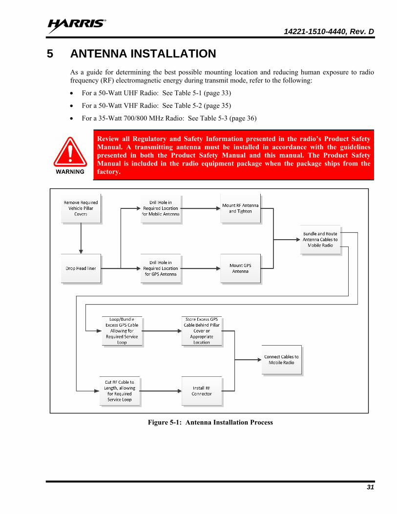
5 ANTENNA INSTALLATION As a guide for determining the best possible mounting location and reducing human exposure to radio frequency (RF) electromagnetic energy during transmit mode, refer to the following:
• For a 50-Watt UHF Radio: See Table 5-1 (page 33)
• For a 50-Watt VHF Radio: See Table 5-2 (page 35)
• For a 35-Watt 700/800 MHz Radio: See Table 5-3 (page 36)
Review all Regulatory and Safety Information presented in the radio’s Product Safety Manual. A transmitting antenna must be installed in accordance with the guidelines presented in both the Product Safety Manual and this manual. The Product Safety Manual is included in the radio equipment package when the package ships from the factory.
Figure 5-1: Antenna Installation Process

14221-1510-4440, Rev. D
32
5.1 ANTENNA MOUNTING LOCATIONS Antennas must be mounted in one of four (4) possible locations on the vehicle. Table 5-1 (UHF), Table 5-2 (VHF) and Table 5-3 (700/800 MHz) show the recommended locations and antenna part numbers. A separation distance of five (5) feet or an intervening ground plane between the antenna, the mobile radio, and accessories is needed to avoid possible interference. See Table 4-3 for additional antenna information.
Review all Regulatory and Safety Information presented in the radio’s Product Safety Manual. A transmitting antenna must be installed in accordance with the guidelines presented in both the Product Safety Manual and this manual.
Failure to mount the antennas in the recommended locations may cause unintended interference.
Always follow the antenna manufacturer’s instructions when mounting an antenna.
Also refer to the respective Recommended Minimum Safe Lateral Distance table presented in the Product Safety Manual. These tables list the recommended minimum safe distance for a controlled environment and for unaware bystanders in an uncontrolled environment, from transmitting antennas (i.e., monopoles over a ground plane, or dipoles) at rated radio power for mobile radios installed in a vehicle.
5.1.1 Direct Center or Center-Rear of Rooftop
The center of the vehicle’s roof is the best location for a rooftop-mount antenna (location in the following figures). For optimal performance, the mounting area under the antenna must be flat with a minimum radius of six (6) inches of metal ground plane. It must be located directly in the center of the roof to minimize human exposure to RF electromagnetic energy. Other obstructions such as a light bar or another antenna may prevent the antenna from being mounted in the direct center of the roof. In this case, the antenna should be mounted a minimum of one foot away from and behind the obstruction but in the middle of the roof with respect to the left and right sides of the vehicle (location in the following figures).
5.1.2 Center of Trunk Lid
Certain vehicles do not allow for the antenna to be placed in the center or center-rear of the roof. In this case, the next best location for the antenna is in the direct center of the trunk lid (location in the following figures). In this case, an elevated-feed-point antenna is recommended. Although this type of antenna does not require a metal ground plane, it must be located directly in the center of the trunk lid to minimize human exposure to RF electromagnetic energy.
5.1.3 Rear Deck Lid for Stand-Alone GPS Receive Antenna
If the XG-25M mobile radio does not use a GPS combination-type antenna and it is equipped with a GPS receiver, a stand-alone GPS receive antenna must be separately located and mounted. The vehicle’s rear deck lid (location in the following figures) is the recommended mounting location for this case. This locates the GPS antenna inside the vehicle.
NOTE

14221-1510-4440, Rev. D
33
Table 5-1: Recommended UHF Antenna Mounting Locations with Antenna Part Numbers
TOP VIEW OF A TYPICAL VEHICLE
ANTENNA PART NUMBER ANTENNA DESCRIPTION*
LOCATION(S)
AN-125001-001 (mount) with AN-225006-001 (element)
132 to 960 MHz, Standard Rooftop-Mount, 0 dBd Gain, ¼-Wavelength, Field-Tuned
AN-125001-001 (mount) with AN-225003-001 (element)
378 to 430 MHz, Standard Rooftop-Mount, 0 dBd Gain
AN-125001-001 (mount) with AN-225003-004 (element)
378 to 430 MHz, Standard Rooftop-Mount, 0 dBd Gain, Low Profile
AN-125001-001 (mount) with AN-225003-005 (element)
378 to 430 MHz, Standard Rooftop-Mount, 2 dBd Gain/4.14 dBi, NGP
AN-125001-001 (mount) with AN-225004-001 (element)
450 to 512 MHz, Standard Rooftop-Mount, 0 dBd Gain
AN-125001-001 (mount) with AN-225004-004 (element)
450 to 512 MHz, Standard Rooftop-Mount, 0 dBd Gain, Low Profile
AN-125001-001 (mount) with AN-225004-005 (element)
450 to 505 MHz, Standard Rooftop-Mount, 2 dBd/4.14 dBi Gain, NGP
AN-125001-003 (mount) with AN-225006-001 (element)
132 to 960 MHz, Thick Rooftop-Mount, 0 dBd Gain, ¼-Wavelength, Field-Tuned
AN-125001-003 (mount) with AN-225003-001 (element)
378 to 430 MHz, Thick Rooftop-Mount, 0 dBd Gain
AN-125001-003 (mount) with AN-225003-004 (element)
378 to 430 MHz, Thick Rooftop-Mount, 0 dBd Gain, Low Profile
AN-125001-003 (mount) with AN-225003-005 (element)
378 to 430 MHz, Thick Rooftop-Mount, 2 dBd/4.14 dBi Gain, NGP
AN-125001-003 (mount) with AN-225004-001 (element)
450 to 512 MHz, Thick Rooftop-Mount, 0 dBd Gain
AN-125001-003 (mount) with AN-225004-004 (element)
450 to 512 MHz, Thick Rooftop-Mount, 0 dBd Gain, Low Profile
AN-125001-003 (mount) with AN-225004-005 (element)
450 to 505 MHz, Thick Rooftop-Mount, 2 dBd/4.14 dBi Gain, NGP
AN-125001-005 (mount) with AN-225006-001 (element)
132 to 960 MHz, GPS Combo Standard Rooftop-Mount, 0 dBd Gain, ¼-Wavelength, Field-Tuned
AN-125001-005 (mount) with AN-225003-001 (element)
378 to 430 MHz, GPS Combo Standard Rooftop-Mount, 0 dBd Gain
AN-125001-005 (mount) with AN-225003-004 (element)
378 to 430 MHz, GPS Combo Standard Rooftop-Mount, 0 dBd Gain, Low Profile
UHF Applications

14221-1510-4440, Rev. D
34
Table 5-1: Recommended UHF Antenna Mounting Locations with Antenna Part Numbers
TOP VIEW OF A TYPICAL VEHICLE
ANTENNA PART NUMBER ANTENNA DESCRIPTION*
LOCATION(S)
(Continued…) AN-125001-005 (mount) with
AN-225003-005 (element) 378 to 430 MHz, GPS Combo Standard Rooftop-Mount, 2 dBd/4.14 dBi Gain, NGP
AN-125001-005 (mount) with AN-225004-001 (element)
450 to 512 MHz, GPS Combo Standard Rooftop-Mount, 0 dBd Gain
AN-125001-005 (mount) with AN-225004-004 (element)
450 to 512 MHz, GPS Combo Standard Rooftop-Mount, 0 dBd Gain, Low Profile
AN-125001-005 (mount) with AN-225004-005 (element)
450 to 505 MHz, GPS Combo Standard Rooftop-Mount, 2 dBd/4.14 dBi Gain, NGP
AN-125001-007 (mount) with AN-225006-001 (element)
132 to 960 MHz, Magnetic-Mount, 0 dBd Gain, ¼-Wavelength, Field-Tuned
AN-125001-007 (mount) with AN-225003-001 (element)
378 to 430 MHz, Magnetic-Mount, 0 dBd Gain
AN-125001-007 (mount) with AN-225003-004 (element)
378 to 430 MHz, Magnetic-Mount, 0 dBd Gain, Low Profile
AN-125001-007 (mount) with AN-225003-005 (element)
378 to 430 MHz, Magnetic-Mount, 2 dBd/4.14 dBi Gain, NGP
AN-125001-007 (mount) with AN-225004-001 (element)
450 to 512 MHz, Magnetic-Mount, 0 dBd Gain
AN-125001-007 (mount) with AN-225004-004 (element)
450 to 512 MHz, Magnetic-Mount, 0 dBd Gain, Low Profile
AN-125001-007 (mount) with AN-225004-005 (element)
450 to 505 MHz, Magnetic-Mount, 2 dBd/4.14 dBi Gain, NGP
AN102800V1 (Discontinued) 136 to 941 MHz, Standard Rooftop-Mount, ¼-Wave, 0 dBd Gain
AN-025187-001 GPS Receive Only, Roof-Mount
AN-025187-003 GPS Receive Only, Magnetic-Mount
* See Table 4-3 on page 29 for detailed antenna descriptions.
UHF Applications

14221-1510-4440, Rev. D
35
Table 5-2: Recommended VHF Antenna Mounting Locations with Antenna Part Numbers
TOP VIEW OF A TYPICAL VEHICLE
ANTENNA PART NUMBER ANTENNA DESCRIPTION*
LOCATION(S)
AN-125001-001 (mount) with AN-225002-001 (element)
136 to 174 MHz, Standard Rooftop-Mount, 0 dBd Gain
AN-125001-001 (mount) with AN-225006-001 (element)
132 to 960 MHz, Standard Rooftop-Mount, 0 dBd Gain, ¼-Wavelength, Field-Tuned
AN-125001-001 (mount) with AN-225002-003 (element)
136 to 174 MHz, Standard Rooftop-Mount, 3 dBd Gain
AN-125001-001 (mount) with AN-225002-004 (element)
136 to 174 MHz, Standard Rooftop-Mount, 2.4 dBd Gain
AN-125001-003 (mount) with AN-225002-001 (element)
136 to 174 MHz, Thick Rooftop-Mount, 0 dBd Gain
AN-125001-003 (mount) with AN-225006-001 (element)
132 to 960 MHz, Thick Rooftop-Mount, 0 dBd Gain, ¼-Wavelength, Field-Tuned
AN-125001-003 (mount) with AN-225002-003 (element)
136 to 174 MHz, Thick Rooftop-Mount, 3 dBd Gain
AN-125001-003 (mount) with AN-225002-004 (element)
136 to 174 MHz, Thick Rooftop-Mount, 2.4 dBd Gain
AN-125001-005 (mount) with AN-225002-001 (element)
136 to 174 MHz, GPS Combo Standard Rooftop-Mount, 0 dBd Gain
AN-125001-005 (mount) with AN-225006-001 (element)
132 to 960 MHz, GPS Combo Standard Rooftop-Mount, 0 dBd Gain, ¼-Wavelength, Field-Tuned
AN-125001-005 (mount) with AN-225002-003 (element)
136 to 174 MHz, GPS Combo Standard Rooftop-Mount, 3 dBd Gain
AN-125001-005 (mount) with AN-225002-004 (element)
136 to 174 MHz, GPS Combo Standard Rooftop-Mount, 3 dBd Gain
AN-125001-007 (mount) with AN-225002-001 (element)
136 to 174 MHz, Magnetic-Mount, 0 dBd Gain
AN-125001-007 (mount) with AN-225006-001 (element)
132 to 960 MHz, Magnetic-Mount, 0 dBd Gain, ¼-Wavelength, Field-Tuned
AN-125001-007 (mount) with AN-225002-003 (element)
136 to 174 MHz, Magnetic-Mount, 3 dBd Gain
AN-125001-007 (mount) with AN-225002-004 (element)
136 to 174 MHz, Magnetic-Mount, 2.4 dBd Gain
AN-025187-001 GPS Receive Only, Roof-Mount
AN-025187-003 GPS Receive Only, Magnetic-Mount
* See Table 4-3 on page 29 for detailed antenna descriptions.
VHF Applications

14221-1510-4440, Rev. D
36
Table 5-3: Recommended 700/800 MHz Antenna Mounting Locations with Antenna Part Numbers
TOP VIEW OF A TYPICAL VEHICLE
ANTENNA PART NUMBER ANTENNA DESCRIPTION*
LOCATION(S)
AN-125001-002 (mount) with AN-225006-001 (element)
132 to 960 MHz Standard Rooftop-Mount, 0 dBd Gain, ¼-Wavelength, Field-Tuned
AN-125001-002 (mount) with AN-225001-001 (element)
700/800 MHz Standard Rooftop-Mount, 3 dBd Gain
AN-125001-002 (mount) with AN-225001-002 (element)
700/800 MHz Elevated-Feed Standard Rooftop-Mount, 3 dBd Gain
AN-125001-002 (mount) with AN-225001-003 (element)
700/800 MHz Elevated-Feed No Ground Plane Standard Rooftop-Mount, 3 dBd Gain
AN-125001-002 (mount) with AN-225001-004 (element)
700/800 MHz Low-Profile Standard Rooftop-Mount, 2 dBd Gain
AN-125001-002 (mount) with AN-225001-005 (element)
700/800 MHz Standard Rooftop-Mount, 5 dBd Gain
AN-125001-004 (mount) with AN-225006-001 (element)
132 to 960 MHz Thick Rooftop-Mount, 0 dBd Gain, ¼-Wavelength, Field-Tuned
AN-125001-004 (mount) with AN-225001-001 (element)
700/800 MHz Thick Rooftop-Mount, 3 dBd Gain
AN-125001-004 (mount) with AN-225001-002 (element)
700/800 MHz Elevated-Feed Thick Rooftop-Mount, 3 dBd Gain
AN-125001-004 (mount) with AN-225001-003 (element)
700/800 MHz Elevated-Feed No Ground Plane Thick Rooftop-Mount, 3 dBd Gain
AN-125001-004 (mount) with AN-225001-004 (element)
700/800 MHz Low-Profile Thick Rooftop-Mount, 2 dBd Gain
AN-125001-004 (mount) with AN-225001-005 (element)
700/800 MHz Thick Rooftop-Mount, 5 dBd Gain
AN-125001-006 (mount) with AN-225006-001 (element)
132 to 960 MHz Thick Rooftop-Mount, 0 dBd Gain, ¼-Wavelength, Field-Tuned
AN-125001-006 (mount) with AN-225001-001 (element)
700/800 MHz GPS Combo Rooftop-Mount, 3 dBd Gain
AN-125001-006 (mount) with AN-225001-002 (element)
700/800 MHz GPS Combo Elevated-Feed Rooftop-Mount, 3 dBd Gain
AN-125001-006 (mount) with AN-225001-003 (element)
700/800 MHz GPS Combo Elevated-Feed No Ground Plane Rooftop-Mount, 3 dBd Gain
AN-125001-006 (mount) with AN-225001-004 (element)
700/800 MHz GPS Combo Low-Profile Rooftop-Mount, 2 dBd Gain
(Continued…)
700/800 MHz Applications

14221-1510-4440, Rev. D
37
Table 5-3: Recommended 700/800 MHz Antenna Mounting Locations with Antenna Part Numbers
TOP VIEW OF A TYPICAL VEHICLE
ANTENNA PART NUMBER ANTENNA DESCRIPTION*
LOCATION(S)
AN-125001-006 (mount) with AN-225001-005 (element)
700/800 MHz GPS Combo Rooftop-Mount, 5 dBd Gain
AN-125001-008 (mount) with AN-225001-001 (element)
132 to 960 MHz Magnetic-Mount, 0 dBd Gain, ¼-Wavelength, Field-Tuned
AN-125001-008 (mount) with AN-225001-001 (element)
700/800 MHz Magnetic-Mount, 3 dBd Gain
AN-125001-008 (mount) with AN-225001-002 (element)
700/800 MHz Magnetic-Mount Elevated-Feed, 3 dBd Gain
AN-125001-008 (mount) with AN-225001-003 (element)
700/800 MHz Magnetic-Mount Elevated-Feed No Ground Plane, 3 dBd Gain
AN-125001-008 (mount) with AN-225001-004 (element)
700/800 MHz Magnetic-Mount Low-Profile, 2 dBd Gain
AN-125001-008 (mount) with AN-225001-005 (element)
700/800 MHz Magnetic-Mount, 5 dBd Gain
AN102800V1 (Discontinued) 136 to 941 MHz Standard Rooftop-Mount, ¼-Wave, 0 dBd Gain
AN-025187-001 GPS Receive Only, Roof-Mount
AN-025187-003 GPS Receive Only, Magnetic-Mount
* See Table 4-3 on page 29 for detailed antenna descriptions.
700/800 MHz Applications

14221-1510-4440, Rev. D
38
5.2 RF ANTENNA INSTALLATION PROCEDURES
An antenna must be installed before completing the radio installation.
Table 4-3 (page 29), Table 5-1 (UHF), Table 5-2 (VHF) and Table 5-3 (700/800 MHz) list the mobile radio antennas approved for use with this mobile radio. As presented in the previous section, various mounting locations exist. Optimal performance is achieved via a rooftop antenna mounted in the direct center of the motor vehicle’s roof.
5.2.1 Installing NMO Antenna Mounts AN-125001-001, -002, -003 and -004
These NMO style antenna mounts can each be used with several different antenna elements. Only limited access under the mounting location is typically required. The installation procedure is presented in Section 5.2.1.3.
5.2.1.1 Standard NMO Antenna Mounts AN-125001-001 and AN-125001-002
This These standard ¾-inch NMO antenna mounts requires a ¾-inch hole in a relatively flat area of the vehicle body, with a vehicle metal thickness of between 0.020 and 0.040 inches. AN-125001-002 has a very-low-loss coax cable (LMR/RF-195 or equivalent).
5.2.1.2 Thick-Roof NMO Antenna Mounts AN-125001-003 and AN-125001-004
This thick-roof NMO antenna mount uses either a ⅜-inch or a ¾-inch mounting hole in a relatively flat area of the vehicle body, with a vehicle metal thickness of between 0.040 and 0.1875 inches (3/16-inch maximum thickness). AN-125001-004 has a very-low-loss coax cable (LMR/RF-195 or equivalent).
For thick-roof NMO antenna mount AN-125001-003 or AN-125001-004, using a ⅜-inch mounting hole requires better access to the underside of the mounting location than if a ¾-inch hole is used. This is because, in the case of a ⅜-inch hole, the antenna mount’s bushing assembly must be inserted from the underside of the mounting surface. When using a ¾-inch mounting hole to mount thick-roof NMO antenna mount AN-125001-003 or AN-125001-004, the thickness of the mounting surface must be at least ⅛-inch (0.125-inch minimum thickness). This requirement is due to the thickness of the alignment ring used to center the bushing assembly within the ¾-inch mounting hole.
5.2.1.3 Installation Procedure for Mounts AN-125001-001 through -004
1. Select the antenna mounting location in accordance with the information presented in the Antenna Mounting Locations section (page 32) of this manual. If necessary, contact the Technical Assistance Center for assistance, see page 86 for contact information.
2. Verify no obstructions exist immediately below the respective mounting location on the underside of the vehicle body, such as vehicle ribbing/body framing, a wiring harness, air bag equipment, etc. Also verify there is a sufficient access path and clearance for the mount’s coax cable. If there is an obstruction or insufficient clearance, select another nearby mounting location.

14221-1510-4440, Rev. D
39
3. Measure and mark the center point of the selected antenna mounting location. Be sure to center the mark from side-to-side of the vehicle.
4. Obtain a hole saw specifically designed for drilling NMO mounting holes of the required diameter. (e.g., Antenex/Laird Technologies model HS34 or equivalent for a ¾-inch hole; Antenex/Laird Technologies model HS38 or equivalent for a ⅜-inch hole).
5. If the vehicle’s headliner panel, carpet, seats, or otherwise, is below the mounting location, move or remove the headliner panel, etc. as necessary to protect it. Alternately, apply a heat-resistant mask material (such as a fiberglass mat or thin sheet metal with masked edges) as required to “catch” the metal shavings and the metal plug (if any) produced by the hole saw. The plug (if any) may be relatively hot if/when it drops out of the saw upon completion of the hole drilling process. ⅜-inch diameter hole saws generally produce only shavings, not plugs.
6. With the hole saw and a drill, drill a hole at the marked hole center point. Position the drill square to (i.e., 90 degrees from) the vehicle mounting surface so paint immediately outside of the perimeter of the hole is evenly removed.
Excessive use of the hole saw and/or failure to position the drill “square” with (i.e., at a 90-degree angle from) the vehicle mounting surface may result in damage to the metal mounting surface, in the area immediately outside of the perimeter of the hole.
7. Ensure the saw removed the paint immediately around the hole as the drilling operation completes. If not, do so by reinserting the saw completely into the hole and spinning it as required. This allows proper grounding via the mount’s lock nut on the top of the mounting surface. On the bottom of the mounting surface, the “teeth” of the mount’s bushing assembly may not provide a good ground due to thick vehicle undercoating, thick primer, oxidation/rust, etc.
8. For a ¾-inch hole, feed the unterminated end of the mount’s coax cable into the hole from the top surface of the vehicle until the mount’s bushing assembly is in position to drop into the hole. The bushing should be tilted at a slight angle and fed into the hole. The threaded shank of the mount’s bushing assembly will not fall through a ¾-inch hole.
For a ⅜-inch hole, feed the threaded shank of the mount’s bushing assembly into the hole from the underside of the mounting surface. Hold it into position until the lock nut is installed.
9. If installing a thick-roof antenna mount (⅜-inch shank) into a ¾-inch hole, place the alignment ring onto the threaded shank of the mount. This ring has an approximate ¾-inch outside diameter.
10. A tube of synthetic lubricant is included with the antenna mount. Apply this lubricant to the mount’s rubber O-ring. Do not get any lubricant on the center contact of the mount’s bushing assembly.
11. As illustrated in Figure 5-2 and Figure 5-3, add the O-ring (C) and lock nut (D) to the top of the mount’s bushing assembly (A). With the O-ring in the groove in the underside of the lock nut, thread the lock nut onto the bushing assembly. Be sure the O-ring remains in the groove before tightening the lock nut.
12. Using a 15/16-inch open-end wrench, tighten the lock nut until it fully compresses the O-ring and makes good contact with the vehicle mounting surface. The groove’s ridges on the bottom of the lock nut must make full contact with the unpainted metal surface of the vehicle.

14221-1510-4440, Rev. D
40
13. Install the antenna element per the procedure in Section 5.2.4.
Figure 5-2: Installing a Standard ¾-Inch NMO Antenna Mount
(e.g., AN-125001-001 or AN-125001-002)
Figure 5-3: Installing a Thick-Roof NMO Antenna Mount
(e.g., AN-125001-003 or AN-125001-004)
5.2.2 Installing NMO Magnetic Antenna Mounts AN-125001-007 and AN-125001-008
1. Thoroughly clean the bottom of the magnetic mount and the selected vehicle mounting surface by removing all dust, dirt, etc.
2. Carefully place the magnet mount onto the metal surface of the vehicle at the selected location. The coax cable exiting the mount’s base should be orientated towards the point at which it will enter into the interior of the vehicle. Do not try to reposition it by sliding it on a painted metal surface.
3. Route the mount’s coax cable to the radio location, passing it by the trunk lid’s perimeter gasket, door perimeter gasket, etc., as necessary.

14221-1510-4440, Rev. D
41
4. Install the antenna element per the procedure in Section 5.2.4.
To remove a magnetic antenna mount, hold it at the bottom of its base and tilt it at an angle to release the magnetic attraction force. Do not pull on the mount’s coax cable. Do not drag the mount across the mounting surface.
5.2.3 Installing All Other Antenna Mounts For any other type of antenna mount not covered in the previous sections, such as GPS combination antennas, install the mount in accordance with the installation instructions included with the mount.
5.2.4 Attaching NMO Antenna Elements
1. Clean the top surface of the NMO mount and the surface of the vehicle immediately around the mount.
2. Place the gasket included with the antenna element (not pictured in Figure 5-2 or Figure 5-3) around the mount and against the surface of the vehicle. If a lubricant or sealant was included with the gasket, apply it to the gasket before placing the gasket.
3. Apply the antenna element to the top of the mount and tighten it in a clock-wise direction (as viewing from the top). Use an appropriate wrench if required. Do not over-tighten.
4. Install a placard (not supplied) on the vehicle’s dash panel, in accordance with the following CAUTION. Place the placard in plain view of the vehicle operator’s position.
Before entering any automatic vehicle (“car”) wash equipment, remove the antenna element from the antenna mount, and secure the element in a safe location inside the vehicle. This will prevent the wash equipment from damaging the element and/or mount. After exiting the wash equipment, thoroughly dry the top of the mount before re-installing the element.
5. Continue with the connection procedure presented in the next section.
5.2.5 Installing the Coax Cable and TNC RF Connector
1. Route the coax cable from the antenna mount to the location where the mobile radio will be installed. Remove headliner panel, interior panels, etc., as necessary. The cable must be kept out of casual contact from persons within the vehicle. Tie and stow the cable as necessary to protect it from possible chafing. Observe and follow this WARNING:
Do not cut an antenna cable any shorter than six (6) feet (1.83 meters), as measured from the base of the antenna mount to the TNC connector that mates to the radio.
2. Using an appropriate crimp tool, crimp the supplied TNC RF connector to the end of the antenna cable. For crimping instructions, see Figure 5-4 or the instructions supplied with antenna mount.

14221-1510-4440, Rev. D
42
3. The antenna cable is connected to the radio’s TNC receptacle-type (female) RF connector per a procedure presented later in this manual. The cable and its TNC connector must be protected from damage, dirt, and/or metal shavings which may be generated during the mechanical and electrical installation of the radio. Temporarily tying the connector and cable-end within a small plastic bag is recommended.
Figure 5-4: Crimping Instructions for TNC RF Connector
All cables should have a service loop near each connector end. Do not bend the cables at severe angles near the connector end. Above all, after all components are installed, verify no cable is under any tension. Failure to do so may lead to damaged cables, causing intermittent radio operation or complete radio failure.
When performing the Performance Test procedures presented in Section 10.3, the following antenna elements must be field-tuned (trimmed/cut) for maximum performance/minimum reflection:
• Part number AN-225002-003 (136 – 174 MHz, 3 dBd) - For length cutting information, see the instructions included with the element.
• Part number AN-225002-004 (136 – 174 MHz, 2.4 dBd) - For length cutting information, see the instructions included with the element.
• Part number AN-225006-001 (132 – 960 MHz, 0 dBd) - For length cutting information, see the charts in Figure 5-5 on page 43, and/or the instructions included with the element.
Other antenna elements used with the radio are factory-tuned and therefore they do not require tuning in the field.

14221-1510-4440, Rev. D
43
Figure 5-5: Cutting Charts for Antenna Element AN-225006-001

14221-1510-4440, Rev. D
44
5.3 GPS RECEIVER ANTENNA INSTALLATION PROCESS
Connecting to a GPS antenna is only required if the (optional) GPS receiver is installed in the radio and its use is required. Refer to Section 8.3 for additional information.
If the XG-25M radio is equipped with the GPS receiver option, the GPS receiver requires connection to an externally-mounted GPS antenna. The GPS antenna must be kept at least six (6) inches away from any other antenna mounted on the vehicle and it must have at least six inches of surface ground plane beneath it.
A combination (“combo”) antenna kit includes a GPS antenna built into the base of the mobile antenna. Refer to Table 4-3 (page 29) for available combo antennas.
5.3.1 General Installation Procedure
1. After selecting a mounting location, install the antenna in accordance with the antenna manufacturer’s mounting and testing instructions.
If necessary, contact the Technical Assistance Center. See page 86 for contact information.
2. Remove headliner panel, interior panels, etc., as necessary.
3. Route the cable from the antenna base to the radio transceiver’s mounting location.
The cable must be kept out of casual contact from persons within the vehicle. Tie and stow it as necessary to protect it from possible chafing. Do not alter the GPS antenna cable length; tie and stow excess cable as necessary.
4. Protect the cable and its (male) SMA connector from damage, dirt, and/or metal shavings which may be generated during the mechanical and electrical installation of the radio. Temporarily tying the connector and cable-end in a small plastic bag is recommended.
The antenna cable will be connected to the radio’s SMA receptacle-type (female) RF connector using a procedure presented later in this manual (i.e., procedure on page 74).

14221-1510-4440, Rev. D
45
5.3.2 Installing a GPS Antenna Inside the Rear-Deck
The following GPS antenna installation procedure is recommended for inside-rear-deck mounting of GPS receive-only antennas, such as AN-025187-001 or AN-025187-003. Many vehicle makes/models, such as the Ford® Crown Victoria®, may use this installation method:
1. Carefully remove the center rear brake light assembly by removing the screws on each side of the assembly. Lift and set it aside.
2. Route the cable from the GPS antenna through the rear deck, next to the cable assembly for the rear brake light.
3. Position the antenna near the rear glass.
For an antenna that is not a magnetic-mount, secure it to the deck near the rear glass in accordance with the instructions provided with the GPS antenna.
4. Reassemble the rear deck brake light assembly.
Use caution to not crimp/pinch the GPS coaxial cable. A small relief notch may need to be cut in the light assembly housing for cable passage.
5. Protect the cable and its (male) SMA connector from damage, dirt, and/or metal shavings which may be generated during the mechanical and electrical installation of the radio. Temporarily tying the connector and cable-end in a small plastic bag is recommended.
6. Route the cable to the area near where the radio will be installed.
7. Tie and stow the antenna cable as necessary to prevent cable chafing or damage from moving items, like the trunk lid’s hinges and springs.
The antenna cable will be connected to the radio’s SMA receptacle-type (female) RF connector using a procedure presented later in this manual (i.e., procedure on page 74).
Do not alter the length of cable from the GPS antenna. The SMA connector on the end of the antenna cable is not field-replaceable.
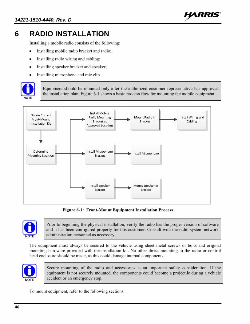
14221-1510-4440, Rev. D
46
6 RADIO INSTALLATION Installing a mobile radio consists of the following:
• Installing mobile radio bracket and radio;
• Installing radio wiring and cabling;
• Installing speaker bracket and speaker;
• Installing microphone and mic clip.
Equipment should be mounted only after the authorized customer representative has approved the installation plan. Figure 6-1 shows a basic process flow for mounting the mobile equipment.
Figure 6-1: Front-Mount Equipment Installation Process
Prior to beginning the physical installation, verify the radio has the proper version of software and it has been configured properly for this customer. Consult with the radio system network administration personnel as necessary.
The equipment must always be secured to the vehicle using sheet metal screws or bolts and original mounting hardware provided with the installation kit. No other direct mounting to the radio or control head enclosure should be made, as this could damage internal components.
Secure mounting of the radio and accessories is an important safety consideration. If the equipment is not securely mounted, the components could become a projectile during a vehicle accident or an emergency stop.
To mount equipment, refer to the following sections.
NOTE
NOTE
NOTE

14221-1510-4440, Rev. D
47
6.1 MOUNTING THE RADIO
This section provides detailed instructions for mechanically installing the XG-25M mobile radio. The instructions apply to front-mounted radios and includes additional information for remoted-mounted radios.
The Mounting Bracket Kit, 14015-0201-01 [item 1 listed in Table 4-1 (page 27)], is used for both front and remote-mounted radios. The kit includes a heavy-gauge steel U-shaped mounting bracket and associated mounting hardware as shown in Figure 6-3. The bracket’s dimensions are shown in Figure 6-4.
Both the radio and the mounting bracket have multiple holes in both sides for adjusting the radio within the bracket. The radio has four (4) threaded mounting holes, two (2) per side, and the mounting bracket has twelve (12) corresponding holes, six (6) per side.
The radio should be attached to a mounting surface using this bracket. The bracket can be mounted above or below the radio and the radio must be secured to the bracket using the four (4) M5 socket-head screws included in the Mounting Bracket Kit (2 screws per side).
The radio can be positioned straight in the bracket (i.e., parallel with the bottom surface of the bracket), or it can be tilted up or down at an angle of approximately 15 degrees maximum. When positioned straight in the bracket, the radio extends approximately 2 inches (5 centimeters) from the front and rear edges of the bracket. In the rear, additional clearance must be included for cables.
• Front-Mount Radio: For a front-mount radio installation, the design allows a front-to-rear tilting of the radio within the bracket for the best viewing angle, and a front-to-rear position offset. Typically, the tilt, or offset, or both, may be applied to a front-mount radio installation to position the front-mount radio for best operator viewing and control access.
• Remote-Mount Radio: For a remote-mount radio installation, the radio bracket tilt and the offset design are generally not put to use, as neither would be necessary. The radio is simply centered within the bracket and parallel with the mounting surface.
The optional CH-25 Remote-Control Conversion Kit includes a mounting bracket for the control head. This bracket allows the head’s tilt to be adjusted for best operator viewing and control access. The Control head installation procedures are included in the Remote-Mount Radio Installation section that begins on page 59.
Observe the follow with respect to clearances at the front of the radio:
• Front-Mount Radio: For a front-mount radio, the area directly at the front of the radio must be completely clear of all objects (e.g., gear shift, other radio equipment, etc.) so the operator can easily access and view the radio.
• Remote-Mount Radio: For a remote-mount radio, the area directly at the front of the radio must have clearance for the installation and removal of the Remote Control Cable. At least 6 inches (15.2 centimeters) of space is recommended.

14221-1510-4440, Rev. D
48
Figure 6-2: XG-25M Front-Mount Radio Dimensions (less Bracket and Cables)
6.1.1 Mounting Bracket Installation
For a remote-mount radio installation, the CH-25 Remote-Control Conversion Kit must be applied to the existing front-mount radio, to convert it to a remote-mount radio with a separate control head. To accomplish this, complete the procedures presented in the kit’s Product Manual, publication number 14221-1510-4450, included with the conversion kit.
After completing the conversion, continue with the radio’s mounting bracket installation.
When selecting a mounting location for the radio, verify sufficient clearance can be maintained around the radio for installation and service access. A minimum clearance of approximately four (4) inches (10 centimeters) is recommended at the rear, left and right sides of the radio. As previously stated, for a front-mount radio, the area directly at the front of the radio must be completely clear of objects so the
7.24 inches(18.4 centimeters)
2.78 inches(7.06 cm)
7.04 inches(17.87 cm)
7.89 inches(20.03 cm)
2.0 in.(5.1 cm)
0.315 in. deep(8.0 cm deep)
M5 Threads(4 Places)
1.180 in.(3.0 cm)0.21 in
(0.53 cm)
6.77 inches(17.2 centimeters)
1.97 inches(5.0 cm)
1.22 inches(3.1 cm)
2.55 inches(6.48 cm)

14221-1510-4440, Rev. D
49
operator can easily access and view the radio’s front panel. For a remote-mount radio, clearance at the front of the radio must be sufficient for removal and attachment of the Remote Control Cable.
The radio’s mounting bracket must be attached to a secure metal surface that meets or exceeds the minimum 1/16-inch-thick steel sheet metal requirement in accordance with the following WARNING. For example, it can be attached directly to the bottom of the dash if the gauge of the sheet metal is high and the surface is firm and flat, or it can be attached to the transmission hump, etc., if a mounting wedge (not included) is utilized. The radio weighs approximately 6 pounds (2.7 kilograms).
At a minimum, the mounting surface should be 16-gauge (approximately 1/16-inch thick) steel sheet metal. Mounting to plastic or other material with low tensile and shear strength could lead to an unsafe and/or failed mounting condition, turning the radio and its mounting bracket into a projectile during a high-shock incident such as a motor vehicle accident. If the selected mounting surface does not meet the minimum 16-gauge steel sheet metal requirement, the surface should be reinforced with a metal backing plate (not supplied) or it should be reinforced using some other approved mounting method.
In addition to improving safety of the installation, firm mounting also prevents unreasonable vibration that could damage the radio, adversely affect transceiver performance and/or cause its cable connections to loosen. An improperly mounted radio may experience degradation in the quality of voice and data communications.
As shown in Figure 6-4, the bracket is both left-to-right and front-to-rear symmetrical. It has eleven (11) holes for securing it to a mounting surface. At least four (4) of these holes must be used to secure the bracket to the mounting surface. Four 1-inch-long #10-32 stainless-steel self-tapping screws are included in the Mounting Bracket Kit for this purpose.
However, some other type of hardware (not supplied) may be used, such as #10-32 stainless-steel self-locking hardware (i.e., machine screws with washers and locking nuts), or self-drilling screws. Self-drilling screws such as “TEK” screws do not require drilling of a pilot hole prior to installation. Do not use common self-threading sheet metal screws because they will loosen over time with vehicle vibrations.
The following mounting procedure is recommended:
1. Determine the best radio-to-bracket position and angle by test-fitting the radio into the mounting bracket at the selected vehicle mounting location.
Slide the radio between the sides of the bracket and temporarily secure it to the bracket with several of the M5 socket-head screws from the bracket kit. Make positional adjustments as necessary.
2. At the rear of the radio, verify sufficient clearance is available for cables and service access.
3. If the mounting surface is not flat (such as the top of a transmission hump), constructing a suitable mounting wedge may be necessary. Attach the wedge to the surface using an approved attachment method. Never mount the bracket directly to a non-flat surface.
4. On the mounting surface, mark the selected location for the bracket, and then remove the radio from the bracket.
5. Clean and remove any foreign material from the mounting surface.

14221-1510-4440, Rev. D
50
Figure 6-3: Mounting Bracket Kit 14015-0201-01
6. Using the bracket as a template, and/or the dimensional information shown in Figure 6-4, mark and drill at least four (4) mounting holes into the mounting surface as required per the type of hardware used.
Before drilling holes and/or installing mounting screws, verify these operations will not damage or interfere with any existing vehicle component (the fuel tank, a fuel line, the transmission housing, existing vehicle wiring, etc.). Always check to see how far the mounting screws will extend below the mounting surface prior to installation. Always deburr drilled holes before installing screws.
7. Temporarily remove the bracket and deburr all of the newly drilled holes.
8. If necessary, apply an approved paint or rust-inhibitor at the holes in the mounting surface.
9. Set the bracket back into place.
10. Install and tighten the mounting screws/hardware.
11. Verify the bracket is firmly secured to the mounting surface. A secure mount prevents unreasonable vibration, which could damage the radio and/or cause its cable connections to loosen.
12. If the rear of the radio is easily accessible when the radio is positioned in the selected position within the bracket, it is recommended that the radio be temporarily inserted into the bracket.
If access is difficult, do not mount the radio into the bracket at this time, because several cable connections must be made at the rear of the radio.

14221-1510-4440, Rev. D
51
Figure 6-4: Mounting Bracket 14015-0201-02 Dimensions (Radio Not Shown)
6.1.2 Inserting the Radio into the Mounting Bracket
The radio should now be inserted into the mounting bracket according to this procedure:
1. Slide the radio into the mounting bracket with the front of the radio facing in the correct direction (usually towards the rear of the vehicle).
2. Secure the radio to the bracket using the four (4) M5 x 10 mm stainless-steel socket-head screws, flat washers, and lock washers.
Each screw should have a lock washer against the screw head and a flat washer against the mounting bracket. This hardware is included with the Mounting Bracket Kit as shown in Figure 6-3. The kit is item 1 listed in Table 4-1 (page 27).
3. Tighten all screws using a 3-millimeter hex key wrench until each lockwasher is fully compressed and the radio is firm and flush between the brackets.
4. Check the mounting area for proper clearance for cable service looping and for air circulation, plus an area to secure and rest the excess cable lengths.
Proper mounting is one factor that ensures optimal radio performance. An improperly mounted radio may experience degradation in the quality of voice and data communications.

14221-1510-4440, Rev. D
52
6.2 RADIO WIRING AND CABLING
The radio’s DC Power Cable, CA-012365-001 (Table 4-1 item 2), has a 3-pin connector, a 20-foot red wire (for the main power connection), a 20-foot white wire (for the switched power source connection), and a 4-foot black wire (for the ground connection). It is supplied with waterproof fuse holders, two AGC-type fuses, and non-insulated ring terminals. The following installation procedures are recommended:
Before making connections to the battery’s positive post, carefully disconnect the battery’s negative (ground) cable(s). This will prevent tools or other metallic objects which come in contact with the battery’s positive terminal from shorting to vehicle ground, causing sparks or even a fire or an explosion!
When disconnecting the negative cable(s), cover/insulate the positive post(s) if it is not already so a tool cannot short between the posts. Some vehicles, such as those with diesel engines have more than one battery; in this case, disconnect the negative cables at all batteries.
Radio fuses should not be installed until all wiring is complete. This will prevent the radio from powering up prematurely and/or causing an in-rush of current that could lead to shorting of the battery, sparks, or even fire.
Plan the routing of the 10-AWG red wire carefully, use an existing access hole in the vehicle’s firewall if possible. Alternately, drill a new hole approximately ½-inch in diameter and install a small rubber grommet (one supplied with the bracket kit) to protect the wire from chafing at the hole’s sharp metal edge.
To prevent fumes from entering the passenger compartment, this hole/grommet/wire combination must also be sealed with a silicon-based sealer before completing the installation.
All cables should have a service loop near each connector end. Do not bend the cables at severe angles near the connector end. Above all, after all components are installed, verify no cable is under any tension. Failure to do so may lead to damaged cables, causing intermittent radio operation or complete radio failure.

14221-1510-4440, Rev. D
53
Figure 6-5: Wiring Diagram for Front-Mount Installations

14221-1510-4440, Rev. D
54
6.2.1 Radio Ground (Black Wire) Connection
Use the following procedure to provide a suitable ground connection for the radio:
1. Connect the radio’s DC Power Cable to the radio by mating its 3-pin connector to the radio’s 3-pin power cable connector.
Visually align the key and firmly push and turn the outer locking ring clockwise until it stops. A click will be sensed to confirm proper mating.
2. Determine a point in the vehicle to provide a permanent ground. This should be a ground point stud or an area of vehicle metal within approximately two (2) feet of the radio.
Proper grounding is crucial to proper radio performance. It is recommended making a continuity check between the battery return connection and chosen ground point.
This surface must have a solid and stable connection to vehicle ground. If not, add grounding strap(s) as necessary.
3. Strip the area of any paint or dirt to expose a bare metal surface, approximately ¾-inch square.
4. Use a through bolt with a nut and lock washer, or bolt to a ground point stud with a nut and lock washer. A self-locking nut can be used instead of a standard nut and lock washer. The stud or bolt must exit the nut with at least three (3) threads.
If necessary, drill a hole in the approximate center of the bare metal surface, and deburr it. A ⅜-inch non-insulated ring terminal is supplied with the cable to make this ground connection. Therefore, the hole diameter should be appropriate for the grounding screw/bolt size and type used to connect the ring terminal to the bare metal surface. This hardware is not supplied.
5. Prepare the ground (black) wire:
Cut the black wire to the required length plus some additional length for a service loop.
Strip insulation back approximately ¼-inch.
Crimp a ⅜-inch non-insulated ring terminal (supplied with the cable) to the end of the black wire.
6. Attach the ring terminal and black wire to the bare metal surface or grounding stud.
The terminal must fit flush against the metal surface. No washer should be installed between the terminal and bare metal surface.
Use stainless-steel self-locking hardware (i.e., machine screws with washers and locking nuts) or other appropriate hardware to ensure a reliable terminal-to-metal contact. Tighten securely.
7. Apply anti-oxidant compound or an approved paint over the terminal and bare metal.
All exposed bare metal and the ring terminal must be covered.
6.2.2 Main Power (Red Wire and Main Fuse Holder) Connection
1. Continue installation of the radio’s DC Power Cable by routing its 20-foot 10-AWG red wire to the location of the vehicle’s battery (or its main DC bus bar or stud).
Remove interior panels, door kick panels, etc., and route the wire through existing channels in the vehicle body as necessary. Protect the wire from possible chafing where necessary.

14221-1510-4440, Rev. D
55
Before making connections to the battery’s positive post, carefully disconnect the battery’s negative (ground) cable(s). This will prevent tools or other metallic objects which come in contact with the battery’s positive terminal from shorting to vehicle ground, causing sparks or even a fire or an explosion!
When disconnecting the negative cable(s), cover/insulate the positive post(s) if it is not already so a tool cannot short between the posts. Some vehicles, such as those with diesel engines have more than one battery; in this case, disconnect the negative cables at all batteries.
Radio fuses should not be installed until all wiring is complete. This will prevent the radio from powering up prematurely and/or causing an in-rush of current that could lead to shorting of the battery, sparks, or even fire.
Do not install any wiring or fuse holder over or in the near vicinity of the vehicle’s engine. Excessive engine heat can cause permanent damage to these components and can lead to intermittent electrical connection to the battery.
Plan the routing of the 10-AWG red wire carefully, using an existing access hole in the vehicle’s firewall if possible. Alternately, drill a new hole approximately ½-inch in diameter and install a small rubber grommet (not supplied) to protect the wire from chafing at the hole’s sharp metal edge. To prevent fumes from entering the passenger compartment, this hole/grommet/wire combination must also be sealed with a silicon-based sealer before completing the installation.
Remote-Mount Radio - In a typical vehicle remote-mount radio installation, as a time-saving measure, most of the Remote Control Cable between the remote-mount radio and the control head can be routed simultaneously with the red and white wires of the radio’s DC Power Cable. Also, the Option Cable from the back of the radio can also be simultaneously routed with most of the length of these two wires and the Remote Control Cable. Detailed installation procedures for the Remote Control Cable are included in Section 7.3 which begins on page 63.
2. Cut the red wire to the required length for connection to the battery’s positive battery terminal (or the main DC bus bar or stud).
3. Obtain the orange waterproof (HFB type) fuse holder included with the DC Power Cable.
Observe and follow the previously presented WARNING!
4. Prepare the red wire for splicing to the fuse holder:
a. Cut the red wire approximately three (3) to six (6) inches from the end.
b. Strip all three (3) wire ends back approximately ⅜-inch.
c. Place a fuse holder shell on each wire, and securely crimp a fuse holder terminal to each wire end.
Before crimping, verify fuse holder shells are oriented in the correct directions (i.e., with each large end towards the wire end).

14221-1510-4440, Rev. D
56
5. Label this fuse holder and red wire appropriately (e.g., “VHF Radio Main Power: 15-AMP FUSE”).
Do not install a fuse into the fuse holder at this time.
6. Crimp a ring terminal to the short red wire.
A corrosion-resistant ⅜-inch ring terminal is included with the cable for this purpose, but another size corrosion-resistant terminal type (not supplied) may be used if required.
7. Connect the ring terminal directly to the battery’s positive post (or if present, to a stud on the battery’s main/non-switched power distribution terminal block).
6.2.3 Ignition Sense (White Wire) Connection
Unlike some remote-mount mobile radio installations, the XG-25M radio’s remote-mount control head installation does not require its own DC power cable and fuse (i.e., separate from the radio). The control head receives DC operating power from the radio via the Remote Control Cable.
A review of the Ignition Sense Location and Considerations information presented in Section 4.4.3 (page 22) may be beneficial at this time. As required per the chosen power-up configuration, connect the white wire by following one of the three procedures presented in the respective sub-section that follows.
6.2.3.1 Radio and Control Head Turn On and Off with Vehicle’s Ignition Switch/Key
With this wiring configuration, the radio and control head automatically turn on and off with the vehicle’s ignition switch/key. The white wire is sometimes referred to as the “white ignition switch wire” or the “ignition sense input wire.” In this configuration, the white wire connects to a switched power source, typically identified as “Accessory” power, that switches on and off with the vehicle’s ignition switch/key. When using this configuration, the radio’s on/off/volume control must be left in the on position for automatic power-up/down to function properly.
The white ignition sense wire must be connected to a fused power source that switches from approximately zero volts to approximately +13.6 volts when the vehicle’s ignition switch/key is turned from the OFF position to the ACCESSORY and RUN positions. Use of a switched power source that is subject to voltage changes as a result of other actions, such as opening a vehicle door, may result in undesirable radio power cycles.
1. Locate the vehicle’s switched ignition or “Accessory” power connection point that will be used for the switched ignition 12-volt DC power source.
This point is typically located at or near the vehicle’s fuse panel. It may be necessary to consult the vehicle manufacturer’s wiring diagram.
2. Route the white wire of the radio’s DC Power Cable from the back of the radio to the area near this connection point. Protect the wire from possible chafing as necessary.

14221-1510-4440, Rev. D
57
3. Obtain the other waterproof (HFB-type) fuse holder included with the radio’s DC Power Cable.
4. Cut excess length from the white wire and splice the fuse holder into it, near the location of the connection point.
5. Using an appropriate electrical terminal, connect the white wire to the switched power connection point. An open-barrel spade terminal is included with the cable for this purpose, but another type of terminal (not supplied) may be used as required.
6. Obtain the 3-amp AGC-type fuse included with the cable, and install it into the fuse holder.
7. Tie and stow all wiring as necessary so it remains out of the way of casual contact and avoids wire chafing.
6.2.3.2 Radio Turns On and Off with a Manual Switch With this wiring configuration, the radio (and its control head) is manually turned on and off via an on/off switch mounted separately from the radio, not through the vehicle’s ignition switch/key. This configuration is used when, for example, the radio must remain on even when the ignition key must be removed from the vehicle and a separate on/off switch is acceptable and/or required. In this configuration, the white wire connects to a fused switched power source such as that provided by a toggle switch mounted on the vehicle’s dash panel. When using this configuration, the control head’s on/off/volume control must be left in the on position for automatic power-up/down to function properly.
1. Route the white wire of the radio’s DC Power Cable from the back of the radio to an area near the location of the panel-mounted on/off switch. Protect the wire from possible chafing as necessary.
2. Cut a short section (6 to 8 inches) off the end of the white wire and strip the ends.
3. Using the other waterproof (HFB-type) fuse holder, included with the radio’s DC Power Cable, crimp one half of it to one end of the short section of wire.
4. Using an appropriate electrical terminal, connect this short white wire to unswitched 12-volt DC power source at or near the vehicle’s fuse box.
5. Cut another section of white wire from the cable. This wire must be long enough to reach from the fuse holder to the location of a panel-mounted on/off switch.
6. Strip one end of this wire and crimp the other half of the waterproof fuse holder to this wire end.
7. Strip the other end of this wire and, using an appropriate electrical terminal, connect it to the common terminal of the switch.
8. Connect the white wire of the power cable to the load (switched) side of the switch.
9. If not already, mount the switch to the vehicle’s dash panel, or other customer-selected location.
10. Obtain the 3-amp AGC-type fuse included with the cable, and install it into the fuse holder.
11. Tie and stow these wires as necessary so they remain out of the way of casual contact and avoids wire chafing.
12. Label this power switch accordingly. For example: “RADIO ON/OFF.”

14221-1510-4440, Rev. D
58
6.2.3.3 Radio Is “Hot Wired” In the “hot-wired” configuration, the radio (and its control head) is turned on and off only by the on/off/volume control located on the front panel of the control head. In this configuration, the white wire must be connected to unswitched and fused 12-volt vehicle power.
Follow the procedure presented in Section 6.2.3.1, except connect the white wire to unswitched battery power instead of switched (“Accessory”) power. Be sure to fuse this connection with the provided in-line fuse holder and 3-amp AGC fuse.

14221-1510-4440, Rev. D
59
7 REMOTE-MOUNT RADIO INSTALLATION Installing a Remote-Mount mobile radio consists of the following:
• Installing the remote mount mobile radio with a control head, and their brackets;
• Installing wiring and cabling
• Installing speaker bracket and speaker;
• Installing mic and mic clip.
Equipment should be mounted only after the authorized customer representative has approved the installation plan. Figure 7-1 shows a basic process flow for installing the remote-mount mobile equipment.
Figure 7-1: Remote-Mount Installation Process
NOTE

14221-1510-4440, Rev. D
60
7.1 MOUNTING THE REMOTE-MOUNT RADIO
Procedures in this section are only for a remote-mount radio installation. For Front mount radio installation, refer to Section 6.
7.1.1 Application of the Remote-Control Conversion Kit
Before beginning remote-mount installation, the control head must be removed from the radio and reconfigured using the CH-25 Remote-Control Conversion Kit, 14015-0203-28 (see Table 4-2). Instructions for reconfiguring the control head are included in the kit’s Product Manual, publication number 14221-1510-4450.
It is critical that the correct minimum version of firmware is loaded into the front-mount XG-25M mobile radio prior to starting the physical conversion/separation process. A remote-mount XG-25M will not recognize the remote-control CH-25 head and the two will be completely non-functional with an older firmware version. Refer to Product Manual publication number 14221-1510-4450 for complete details. The manual is included with CH-25 Remote-Control Conversion Kit DM-ZN9Z.
The manual includes procedures for removing the control head from the existing front-mount radio, attaching the radio’s remote interface to the front of the radio thus converting it to a remote-mount radio, and attaching the control head’s remote interface to the back of the control head.
At a minimum, the mounting surface should be 16-gauge (approximately 1/16-inch thick) steel sheet metal. Mounting to plastic or other material with low tensile and shear strength could lead to an unsafe and/or failed mounting condition, turning the radio and its mounting bracket into a projectile during a high-shock incident such as a motor vehicle accident.
If the selected mounting surface does not meet the minimum 16-gauge steel sheet metal requirement, the surface should be reinforced with a metal backing plate (not supplied) or it should be reinforced using some other approved mounting method.
Though generally mounted in a trunk or remote location, the remote-mount mobile radio must be kept away from heat sources. Mounting it in a location which is out of direct sunlight is recommended but not required.
Adequate ventilation space must be provided to the side fins. The radio reduces its RF output power when its ambient temperature exceeds approximately +140 o Fahrenheit (+60o Celsius).
Before drilling holes and/or installing mounting screws, verify these operations will not damage or interfere with any existing vehicle component (the fuel tank, a fuel line, the transmission housing, existing vehicle wiring, etc.). Always check to see how far the mounting screws will extend below the mounting surface prior to installation. Always deburr drilled holes before installing screws.

14221-1510-4440, Rev. D
61
Ensure all equipment is protected from possible damage.
• Position the equipment (especially control heads) to avoid direct impact from water and hose-down, snow, dust, smoke, gases, road debris, oils, chemicals and corrosive agents.
• If installing equipment behind a door or cover in a protective enclosure, always ensure there is adequate airflow and cooling.
• Use of splash guards, shields, or covers, to protect against direct impacts.
The equipment must always be secured to the vehicle using sheet metal screws or bolts and original mounting hardware provided with the installation kit. No other direct mounting to the radio or control head enclosure should be made, as this could damage internal components.
When mounting radio equipment in the vehicle trunk always be aware of the position of the vehicle’s gas tank. Ensure the radio’s mounting screws do not penetrate the vehicle‘s gas tank.
To mount equipment, refer to the following sections.
7.1.2 Installing the Remote-Mount Radio
After completing the procedures in Product Manual 14221-1510-4450, install the radio mounting bracket as described in Section 6.1.1 on page 48. Then install the remote-mount radio into its mounting bracket by following the procedure in Section 6.1.2 on page 51.
Also connect/re-connect the 3-pin connector of the DC Power Cable to the 3-pin power connector on the rear of the radio. Instructions for installing the power cable are provided in Section 6.2, starting on page 52.
7.2 CONTROL HEAD MECHANICAL INSTALLATION
After the CH-25 Remote-Control Conversion Kit is applied and the radio is installed into its mounting bracket, continue by installing the control head, as described in the following subsections:
7.2.1 Selecting the Mounting Location
Secure mounting of the radio, control head, and accessories is an important safety consideration. If the equipment is not securely mounted, the components could become a projectile during a vehicle accident or an emergency stop. Proper mounting is one factor that ensures optimal radio performance. An improperly mounted radio may experience degradation in the quality of voice and data communications.
When selecting a location for the control head, first review and observe the safety and operator-convenience related information presented in Section 4.4 on page 20. Always consider and include clearance for the microphone’s connector that must mate to the mic connector on the front panel of the head, and clearance for the connector of the Remote Control Cable’s that mates to the connector on the rear panel of the head. The control head can be mounted in, under, or on top of a mounting surface (typically the vehicle’s dash) as space permits.
The size and weight of the control head necessitate less stringent mounting requirements than the radio. However, like the radio, the control head must be mounted to a mechanically-rigid surface. It must not vibrate when the vehicle is in motion and it must remain stable during normal operations by a radio
NOTE

14221-1510-4440, Rev. D
62
operator (i.e., button presses, knob rotation, excessive tugs on the mic cord, etc.). If the control head is mounted to a plastic or similar-type dash panel, either fender washers or a field-fabricated metal backing plate should be utilized on the opposite side of the panel from the bracket.
7.2.2 Installing the Mounting Bracket and Control Head
Follow this procedure to mechanically install the control head’s mounting bracket and attach the head to it:
1. Obtain the mounting bracket from the conversion kit. The bracket is illustrated in Table 4-2 on page 28.
The control head can be attached above its mounting surface, like on the top of a dash panel. In that case, the bracket is located below the head, as shown in Figure 7-2.
Alternately, the head can be attached below its mounting surface, such as underneath a dash panel. In that case, the bracket is located above the head.
Figure 7-2: Control Head Mounting Bracket (shown positioned below head)
Before drilling holes and/or installing mounting screws, verify these operations will not damage or interfere with any existing vehicle component (the fuel tank, a fuel line, the transmission housing, existing vehicle wiring, etc.). Always check to see how far the mounting screws will extend below the mounting surface prior to installation. Always deburr drilled holes before installing screws.
1. Using the mounting bracket as a template, mark and drill mounting holes into the mounting surface as required. When positioning the bracket, note that the chamfered edge-slots on each end of the bracket must face in the same direction as the control head’s display will need to face. In a typical vehicle installation, this is towards the rear of the vehicle.
14221-1510-4440, Rev. D
63
2. If necessary, deburr the newly drilled holes.
3. Set the bracket back on the mounting surface, positioning it so its chamfered edge-slots are facing in the same direction as the head’s display will need to face.
4. Install and tighten the mounting screws. Screws for mounting the bracket to the mounting vehicle’s surface are not included, as all installations differ. Self-threading screws are recommended. Use of self-drilling screws may cause damage to some mounting surfaces, such as a plastic dash panel.
5. Verify the bracket is held firmly to the mounting surface. Firm mounting prevents unreasonable vibration, which could damage the control head and/or cause its cable connections to loosen. Bracket attachment must survive all expected radio operator actions such as hard button-press actions and excessive tugs on the mic cord.
6. Install the control head into the bracket by sliding the short pegs protruding from the left and right sides of the head into the chamfered edge-slots on each end of the bracket.
7. At each end of the bracket, start a socket-head cap (Allen) head screw with a flat washer by inserting the screw (with washer) through the arched hole in the bracket and then into the threaded hole in the side of the control head. This hardware is included with the Mounting Bracket Kit. Start both screws, with one washer each. Turn each screw in clockwise direction to start it into the threaded hole.
8. Tilt the head in the bracket to the required angle for best viewing by the operator at his/her normal position, and then fully tighten both screws using a 4-millimeter hex key (Allen) wrench. Recommended torque is 8.7 inch-pounds (10 kgf-cm). Do not over-tighten.
Each cap screw should not be installed/re-used more than eight (8) times, because thread locking strength may suffer after this number of re-installations. Replace the cap screws with new cap screws if their locking strength is in question and/or after exceeding eight (8) installations.
7.3 INSTALLING THE REMOTE CONTROL CABLE
Follow this procedure to install the Remote Control Cable:
1. Obtain Remote Control Cable 14015-0203-31. The cable is included in CH-25 Remote-Control Conversion Kit DM-ZN9Z. It is 30 feet (9.1 meters) long.
2. Connect one of the Remote Control Cable’s 44-pin connector to the 44-pin connector on the front of the radio. Before connecting either connector, note the following:
As illustrated in Figure 7-3, the cable of the Remote Control Cable exits each D-shaped connector of the cable in opposite directions with respect to the D shape of each connector. At one connector, it exits to the right and at the other connector, it exits to the left (assuming the D-shapes are orientated in the same direction as shown in the figure). Also, from an electrical stand-point, both connectors have identical pin-outs.
As shown in Figure 7-4 on page 64, this allows the Remote Control Cable to be reversed (radio<>head) to reverse the left/right orientation of the cable in relation to the left/right sides of the radio and head. This may be advantageous for some installations where, for example, cable clearances

14221-1510-4440, Rev. D
64
are tight on one side of the radio and/or head, or cable routing and service loop routing benefits from one direction over another.
Be sure to leave a service loop in the cable so when radio removal is necessary, movement will not be unnecessarily limited.
Figure 7-3: D-Shaped Connectors of Remote Control Cable
Always use a flat-blade screwdriver with a ¼-inch tip to tighten and loosen the jackscrews of these two connectors. Do not exceed 6.0 inch-pounds of torque (6.9 kgf-cm) when tightening the jackscrews.
1. Route the cable through the vehicle’s interior to near the location of the control head. Remove interior panels, door kick panels, etc., and route the cable through existing channels in the vehicle body as necessary.
2. Connect the other 44-pin connector of the Remote Control Cable to the 44-pin connector on the rear panel of the control head. Tighten the jackscrews securely, but do not over-tighten them. Be sure to leave a service loop in the cable so when control head removal is necessary, movement will not be unnecessarily limited.
3. Tie and stow all excess cable length so it will be out of casual contact with vehicle occupants. Be sure to protect it from wire chafe where necessary.
4. Re-install all previously removed interior panels, door kick panels, etc.

14221-1510-4440, Rev. D
65
Figure 7-4: Left Side/Right Side Remote Control Cable Orientation

14221-1510-4440, Rev. D
66
8 OPTIONS AND ACCESSORIES 8.1 EXTERNAL SPEAKER INSTALLATION (OPTIONAL)
The XG-25M mobile radio has an internal (built-in) speaker in the front panel of the control head. This speaker’s audio output power level is rated at 3 watts maximum. It is driven by an audio amplifier located inside the radio.
The radio has another internal speaker audio amplifier. This amplifier can drive an optionally-installed external speaker at up to 15 watts. When the external speaker is on/enabled, the radio’s internal speaker remains off/disabled (muted).
If an external speaker is required, install it according to the below procedure. Total available cable length for an external speaker is approximately 10 feet (308 centimeters). Therefore, to include service loops in these cables, the speaker must be mounted within approximately 9.5 feet (290 centimeters) of the radio. This requirement assumes standard cabling is used.
1. Obtain Speaker LS102824V10. This speaker is rated for audio levels up to 20-watts.
2. Obtain Option Cable 14002-0174-08.
3. Select a location for the speaker that will allow for proper listening range with a moderate volume setting.
4. Install the speaker using the hardware and mounting bracket supplied with it. Route the speaker cable to the rear of the radio.
5. Connect the Option Cable to the DB-44 connector on the rear of the radio. Tighten the cable’s two (2) jackscrews securely. See Section 9.1 for additional information on this cable.
6. Mate the Option Cable’s 2-pin connector (identified P2) to the 2-pin connector on the end of the speaker cable. A mild click will be sensed to confirm proper mating.
7. Route the cables out of the way of casual contact. Tie and stow as necessary.
To support the external speaker, the radio must have the EXT SPKR (External Speaker) function programmed to a radio button and/or menu. With this programming, the external speaker can be toggled on and off by pressing the button programmed with this function, or by selecting the function on a menu. When the external speaker is on, the radio’s internal speaker remains off/disabled.
8.2 MICROPHONE ATTACHMENT
The XG-25M radio’s microphone has a coiled cord and a 12-pin connector. The connector mates with the mic connector on the front panel of the control head.
A microphone hanger is included with each microphone. The radio can be configured to provide a monitor function when the microphone is inserted into the hanger.

14221-1510-4440, Rev. D
67
Use the following procedure to connect the mic to the control head and install the mic hanger:
1. Position the mic’s connector just in front of the radio’s mic connector so it can engage straight into the mic connector. The small notch on the end of the mic’s connector must be positioned straight up so it engages with the key in the connector of the radio.
2. Mate the two connectors by pressing them fully together. A click should be sensed when the connectors latch together.
3. Using the microphone hanger as a template, drill mounting holes in the surface of the selected location.
4. Select a mounting surface location that has clearance for the mic when it is clipped to the clip, and then attach the microphone clip to the surface. Use self-locking hardware (i.e., machine screws with washers and locking nuts), self-drilling screws, or other appropriate hardware as necessary. Tighten securely. The microphones have integrated hookswitches. Therefore, the microphone clip does not need to be grounded.
5. Clip the microphone to the clip.
Harris mobile radio microphones and Harris mic hangers are mechanically optimized to coexist with each other. The mic hanger’s part number is 344A4678P1. The use of a third-party mic hanger with a Harris microphone could potentially result in damage to the microphone and/or inhibit normal radio operation.
8.3 GPS NMEA-FORMATTED DATA CONNECTION
To obtain GPS NMEA-formatted serial data from the radio, the radio must be equipped with the GPS receiver option, and Option Cable 14002-0174-08 is required. For radios equipped with a GPS receiver, follow this procedure to complete the GPS NMEA-formatted serial data connections:
1. Obtain Option Cable 14002-0174-08. Each “leg” of this cable is approximately 65 inches long (166 centimeters).
2. Connect the cable’s 44-pin D-subminiature (DB-44) male connector to the DB-44 female connector on the rear panel of the radio. Tighten the two jackscrews with a small flathead screwdriver. Do not over-tighten.
3. Connect the cable’s DB-9 female connector identified as P5 to the computer’s serial port DB-9 male connector—either directly or extended via cable CA-013671-020 (a 20-foot-long cable); see Section 9.2. Tighten the screws firmly, and then route the cabling as required. If the computer is not equipped with a DB-9 serial port connector, the use of a suitable adapter is required, such as USB-to-RS-232 Adapter Cable CN24741-0001.
4. Follow the manufacturer’s instructions on processing the NMEA-formatted GPS data from the radio.
If the Option Cable 14002-0174-08 is not available, a 3-wire serial cable can be field-fabricated. On the radio end, this cable must interface to the three GPS-related signals of the radio’s 44-pin I/O Cable connector (pins 7, 31, and 32). See 9.1 for additional information.
Industry software to process GPS information through this interface is not supported by Harris.

14221-1510-4440, Rev. D
68
8.4 MOBILE DATA CONNECTION If the radio installation must support mobile data communications of a computer running Mobile Data Terminal (MDT) or similar software, follow this procedure to connect the computer to the radio:
1. Obtain Option Cable 14002-0174-08. Each “leg” of this cable is approximately 65 inches long (166 centimeters).
To use a SLIP/PPP connection, Option Cable 14002-0174-08 Rev. A (or later) is required. Earlier cables did not have the CTS and RTS interconnections to connector P6 and CTS/RTS is needed for a SLIP/PPP connection.
2. Connect the cable’s 44-pin D-subminiature (DB-44) male connector to the DB-44 female connector on the rear panel of the radio. Tighten the two jackscrews with a small flathead screwdriver. Do not over-tighten.
3. Route the “leg” of this cable that has the two DB connectors (i.e., DB-25 connector P4 and DB-9 connector P6) to the area near the serial port of the MDT computer. Protect the cable from possible chafing and tie-and-stow it as necessary.
If the cable’s “leg” length is not long enough to reach the computer, obtain cable CA-013671-020 (or equivalent) and use it to extend the connection from the DB-9 connector P6. Cable CA-013671-020 is a 20-foot-long standard DB-9 serial data cable.
4. Connect the female DB-9 connector (P6) to the computer. If the computer is not equipped with a DB-9 serial port connector, use a suitable adapter, such as USB-to-RS-232 Adapter Cable CN24741-0001.
Before data communications can occur on a P25 system, the respective data option must be enabled. Contact the Technical Assistance Center (TAC) for additional information. TAC contact information is included on page 86.

14221-1510-4440, Rev. D
69
9 OPTIONAL CABLES 9.1 OPTION CABLE 14002-0174-08
Option Cable 14002-0174-08 connects to the 44-pin I/O connector on the rear of the radio. It breaks out into several smaller standardized connectors, allowing straightforward access to external interfaces provided by the radio. The cable is shown in Figure 9-1. The cable’s 44-pin D-subminiature connector that mates with the connector on the rear of the radio is identified P1.
(Made From D14002-0174 Sh. 11 and 12, Rev. C)
Figure 9-1: Option Cable 14002-0174-08
P1(Pin-Out View)
ASSEMBLY DIAGRAM
WIRING DIAGRAM
P1(Side View) P2
P3
P5
P4
P6
Approximately 66 inches(170 centimeters)
WIRECOLOR
WIREGAUGE SIGNAL NAME
IMAGE
14221-1510-4440, Rev. D
70
Observe caution before connecting any external device to the radio via its 44-pin I/O connector. If an external device has its own DC power source/cable (i.e., if it is powered separately from the radio), both the radio and the external device must be properly grounded before connecting the two units and before making a positive (+) power connection to either unit. Otherwise, fuse(s) inside the radio may fail (open) and/or other equipment damage could occur.
Connector P2 is the cable’s 2-pin connector that provides connections for an optional speaker. Connection is not required if only the radio’s internal speaker will be used.
Connector P3, the cable’s 6-pin connector, is a connector for basic accessories (e.g., hookswitch, etc.).
Connector P4, the cable’s D-subminiature 25-pin connector, provides audio and data connections for optional equipment.
Connector P5, a D-subminiature 9-pin connector, provides NMEA-formatted GPS serial data connections for the external computer processing the NMEA-formatted GPS data received by the radio’s internal GPS receiver. See Section 8.3 on page 67 for additional information. This is serial port A of the radio.
Connector P6 provides a serial data interface used for radio programming. Like P5, this is a D-subminiature 9-pin connector. This is serial port B of the radio.

14221-1510-4440, Rev. D
71
9.2 SERIAL DATA CABLE CA-013671-020
Serial Data Cable CA-013671-020 (20 feet long) can be used to extend data connections from the radio to data communications equipment such as a Mobile Data Terminal (MDT) or a GPS NMEA-format device. The cable’s assembly and wiring diagrams are shown in Figure 9-2.
The cable’s male DB-9 connector (J1) mates to a female DB-9 serial port connector of Option Cable 14002-0174-08, either connector P5 or P6.
The cable’s female DB-9 connector (J2) mates to a PC’s male DB-9 serial port connector. If the utilized PC is not equipped with a DB-9 serial port connector, the use of a suitable adapter is required, such as USB-to-RS-232 Adapter Cable CN24741-0001. As of the publication of this manual, CN24741-0001 is available via the Customer Care center; refer to Section 3.3 on page 17 for contact information.
(Made From PS-CA-013671 Rev. -)
Figure 9-2: Serial Data Cable CA-013671-020

14221-1510-4440, Rev. D
72
9.3 FRONT PANEL PROGRAMMING CABLE 14015-0200-01
Front Panel Programming Cable 14015-0200-01 can be used to program and configure the radio via the microphone connector on the front panel of the radio. The cable’s assembly and wiring diagrams are shown in Figure 9-3. The terminals/pins of the mic connector include those of a serial programming port. The radio auto-senses between a serial device connected to the serial programming port of the mic connector and the serial programming port of the rear panel connector.
If using ECP Release R16B08 or earlier or XGP Release R1A34 or earlier, the radio cannot be flashed and its personality cannot be programmed using the Front Panel Programming Cable. Refer to TAC’s Important Product Notification (IPN) Volume 5 Number 6 for additional information.
The cable’s circular (LTW) connector mates to the radio’s mic connector, and its female DB-9 connector mates to a male DB-9 serial port connector of a computer (or USB adapter). If the utilized PC is not equipped with a male DB-9 serial port connector, the use of a suitable adapter is required, such as USB-to-RS-232 Adapter Cable CN24741-0001. As of the publication of this manual, CN24741-0001 is available via the Customer Care center; refer to Section 3.3 on page 17 for contact information.
(Made From D14015-0200-PS Rev. A)
Figure 9-3: Front Panel Programming Cable 14015-0200-01

14221-1510-4440, Rev. D
73
9.4 DESK MIC ADAPTER CABLE 14015-0200-02
Desk Mic Adapter Cable 14015-0200-02 can be used to connect a desk microphone, such as part number MC-014121-003. This cable interconnects the radio’s front panel mic connector to the desk mic’s DB-9 connector. Cable assembly and wiring diagrams are shown in Figure 9-4.
The cable’s circular (LTW) connector mates to the radio’s mic connector, and its female DB-9 connector mates to the male DB-9 connector of the desk mic.
(Made From D14015-0200-PS Rev. A)
Figure 9-4: Desk Mic Adapter Cable 14015-0200-02

14221-1510-4440, Rev. D
74
10 INSTALLATION INSPECTION AND TESTS 10.1 REQUIRED TEST EQUIPMENT
Table 10-1: Test Equipment Required for Performance Tests
TEST EQUIPMENT MODEL / PART NUMBER & DESCRIPTION
Average-Responding Wattmeter
(for conv. measurements) Bird Electronic Corp. Model 43 (or equivalent) with Type N female connectors at input and output ports.
Digital Wattmeter Bird Electronics Corp Model 5000-XT with Wideband Power Sensor 5017, 25 MHz to 1000 MHz Range.
Wattmeter Element
(Typically Not Required if Using a Digital Wattmeter)
For VHF Radio: Bird Electronic Corp. Element 100C (100-Watt max.) 100 - 250 MHz frequency range (or equivalent). For 50-Watt UHF Radio: Bird Electronic Corp. Element 100D (100-Watt max.) 200 – 500 MHz frequency range (or equivalent). For 700 & 800 MHz Radio: Bird Electronic Corp. Element 50E (50-Watt max.) 400 - 1000 MHz frequency range (or equivalent).
RF Coaxial Jumper Cable
Pasternack Enterprises PE3661-36 (or equivalent) 50-Ohm Coaxial Cable with TNC male connector and Type N male connector, approximately three (3) feet in length. The utilized cable must have VSWR below 1.5:1 within the RF passband.
N-to-TNC RF Adapter
Pasternack Enterprises PE9090 (or equivalent) Type N male to TNC female adapter. Required to connect the cable of the vehicle-mounted antenna to the wattmeter.
50-Ohm RF Terminator (“Dummy Load”)
Pasternack Enterprises PE6167 (or equivalent) 50-ohm RF terminator rated at 50 watts or greater, with Type N male connector.
Vehicle-Mounted Antenna
Tests are performed with the vehicle-mounted antenna per the installation described in Section 5 of this manual.
or

14221-1510-4440, Rev. D
75
10.2 INITIAL POWER-UP TEST
1. At the radio’s main waterproof (HFB-type) fuse holder installed near the vehicle battery, insert the 15-amp fuse that was included with the radio’s DC Power Cable.
2. Install the Ignition Sense 3-amp AGC-type fuse, if not already installed.
3. Tie and stow all fuse holders at this location to prevent excess vibration/movement.
4. Carefully reconnect the vehicle’s battery ground cable.
5. If not already, temporarily connect the mobile antenna cable from the vehicle-mounted mobile antenna to the female TNC RF connector on the rear panel of the radio.
This is a temporary connection until test procedures in Section 10.3 are complete.
6. If the radio is equipped with the GPS receiver option, permanently connect the antenna cable from the GPS antenna (or mobile/GPS combo antenna) to the female SMA connector on the rear panel of the radio.
The male SMA connector on most GPS antenna cables has a 5/16-inch hex collar, so the use of a wrench of this same size is normally required for tightening. However, some may have collars with only knurled surfaces, so a standard wrench or torque wrench cannot be used. In either case, do not over tighten the connector and do not twist the cable when tightening.
7. If the installation is wired so the vehicle’s ignition key/switch turns the radio on and off, turn the switch to the Accessory or Run position.
8. If the radio is not already powered up, do so by rotating its on/off/volume control clockwise out of the detent position.
9. Verify the radio has powered-up by observing its display.
As long as the software configuration parameters have been loaded, successful installation is almost immediately realized:
• After a short boot-up sequence, the radio displays login information and/or a talk group.
• If no errors are displayed, the installation is most-likely properly wired.
• If an error is displayed, recheck all cable connections, verify all fuses are properly installed, and verify battery power on the load side of the fuses, etc. If problems persist, contact the Technical Assistance Center (see page 86).
• Consult the Operator’s Manual for operational information.
Refer to Section 10.3 for performance test information.

14221-1510-4440, Rev. D
76
10.3 PERFORMANCE TESTS
This section includes procedures to verify the performance of the installation’s mobile antenna system. There are two (2) procedures in this section: • Testing by Transmitting into a Dummy Load (a 50-Ohm RF Terminator) • Testing by Transmitting into the Mobile Antenna
If the vehicle’s engine must remain running, the vehicle location should be well ventilated so exhaust fumes from the engine do not cause harm!
The accuracy of test results depends upon a DC power source in the range of 13.6 volts DC ±10%. The current capacity of the power source must be greater than 15 amps. Make sure the vehicle’s battery is fully charged by running the engine for a few minutes before the test, and keep the engine running during the test procedures. Observe the previous WARNING!
If a vehicle equipped with this radio requires jump-starting, the radio installation’s main fuse should be removed from the holder prior to jump-starting. Doing so will prevent damage to the radio system.
Prior to installation, the radio’s power level should be configured appropriately. The wide range of power levels indicated in the following procedures takes into account such things as: customer’s requirements; measurement errors, especially to include uncalibrated equipment; cabling losses; and voltage and temperature variations. By no means should the result from Performance Testing in this section be construed as the exact power level output from the radio, as the level is set and more accurately measured in the factory. The levels obtained in these test procedures determine a successful installation only.
10.4 RF POWER TESTS
10.4.1 Transmitting into a 50-Ohm Dummy Load
1. Turn off the radio.
2. Using the Type N male to TNC male RF coaxial jumper cable, connect the radio’s antenna connector to the wattmeter’s input connector. Refer to Figure 10-1 as necessary.
3. Connect the 50-ohm dummy load to the wattmeter’s output connector, in place of the antenna cable from the vehicle-mounted antenna.
4. Turn on the radio and set it to the required operating mode (based upon available radio programming and test equipment).

14221-1510-4440, Rev. D
77
5. Set the radio to a test conventional channel that is approximately in the middle frequency range of the radio installation’s antenna element.
6. Position the wattmeter’s element to measure forward RF output power. Rotate it if necessary. The arrow on the face of the element must point away from the radio and towards the dummy load for forward power measurements.
7. Set the wattmeter to measure average RF power.
It is recommended that a test talk group/channel be allocated for this testing. This same group should be used during the antenna test procedure which is presented in the subsequent section.
Figure 10-1: Wattmeter Connections for Antenna System Tests
8. Key the radio’s transmitter via the microphone’s PTT button.
9. Verify the measured transmit output power is within the respective range listed in Table 10-2. The respective power setting listed in this table assumes the radio is currently configured at the maximum transmit power level.
Transmit only for as long as needed to take the measurement, then immediately disable the transmission.
The 700/800 MHz XG-25M radio is aligned for a maximum transmit power of 35 watts across the entire 700/800 MHz frequency band. However, for FCC licensed systems, verify the radio’s 700 MHz channels are limited to 30 Watts or per license requirements via the radio’s personality programming.

14221-1510-4440, Rev. D
78
The UHF XG-25M radio is aligned for a maximum transmit power of 50 watts across its entire 378 - 470 MHz operating band. However, for equipment operating in accordance with FCC 47CFR80 rules (i.e., Maritime Services), it is the responsibility of the licensee to ensure the radio is installed and aligned per license requirements.
Table 10-2: Transmit Power Ranges with Radio Maximum Power Levels
RADIO MAXIMUM TRANSMIT
POWER
APPLICABLE RF BANDS
MINIMUM MEASURED TRANSMIT
OUTPUT POWER (Watts) (-1 dB)
TRANSMIT OUTPUT POWER SETTING (Watts)
MAXIMUM MEASURED TRANSMIT
OUTPUT POWER (Watts) (+1 dB)
50 Watts VHF and UHF 39.8 50 63
35 Watts 700 MHz 23.8 30
(see NOTE) 37.7
800 MHz 27.8 35 44.1
10. If the wattmeter reading is within that range, record the measured level in the appropriate space on the Installation Checklist near the end of this manual.
If the wattmeter reading is outside that range, verify the radio’s power supply voltage (i.e., battery voltage) is within the specified range, recheck all connections, and measure the RF output power again. If this fails to produce a reading within the range, replace it and repeat this procedure. If problems persist, contact the Technical Assistance Center (see page 86).
10.4.2 Transmitting into the Mobile Antenna
1. Turn off the radio.
2. Connect the antenna cable from the vehicle-mounted antenna to the wattmeter as shown in Figure 10-1.
3. Turn on the radio and set it to the required operating mode (based upon available radio programming and test equipment).
4. Set the radio to a test conventional channel that is approximately in the middle frequency range of the radio installation’s antenna element.
It is recommended that a test conventional channel be allocated for this testing. Otherwise, interference with other radio users in the system may occur. Also, during transmissions, always observe the RF exposure-related safety information presented in XG-25M radio’s Product Safety Manual.
5. Position the wattmeter’s element to measure forward RF output power. Rotate it if necessary. The arrow on the face of the element must point away from the radio and towards the antenna for forward power measurements.
6. Set the wattmeter to measure average RF power.

14221-1510-4440, Rev. D
79
7. Key the radio’s transmitter via the microphone’s PTT button.
8. Verify the measured transmit output power is within the respective range listed in Table 10-2. The respective power setting listed in this table assumes the radio is currently configured at the maximum transmit power level.
Transmit only for as long as needed to take the measurement, then immediately disable the transmission.
9. If the wattmeter reading is within the range, record the level in the appropriate space on the Installation Checklist near the end of this manual.
If the wattmeter reading is outside the range, verify the radio’s power supply voltage (i.e., battery voltage) is within the specified range, recheck all connections, and measure the forward power again. If the installation employs a ¼-wave unity-gain antenna, observe the following NOTE. If these checks/corrections fail to produce a reading within the range, check all cabling and connections and repeat the testing procedure to this point. In the event the wattmeter reading still falls outside the range, replace the antenna, make sure all connections are seated firmly, and repeat the testing procedure. If problems persist, contact the Technical Assistance Center (see page 86).
If the radio installation employs a ¼-wave unity-gain antenna (part number AN-225006-001), the driven element (i.e., whip) of the antenna must be trimmed to the proper length in order to minimize antenna system VSWR. Refer to the instructions included with the antenna for trimming instructions.
10. Position the wattmeter’s element to measure reverse (reflected) RF power from the antenna. The arrow on the face of the element must point away from the antenna and to the radio to measure reverse power.
11. Key the radio’s transmitter via the microphone’s PTT button.
Transmit only for as long as needed to take the measurement, then immediately disable the transmission.
12. For a good mobile radio installation, an antenna system VSWR of between 1.2:1 and 1.5:1 is reasonable. If the utilized wattmeter/power-meter cannot directly measure and display VSWR, use the following formula to calculate the reverse power at a 1.5:1 VSWR level:
Preflected (Watts) = Pforward (Watts) * 0.04, where Pforward (Watts) is the measured forward power.
For example: For a Pforward of 30 Watts, Preflected = 30 * 0.04 = 1.2 Watts. See Table 10-3 for more examples.

14221-1510-4440, Rev. D
80
Table 10-3: Example Measured Forward Power Levels to Reflected Power Levels for a 1.5:1 VSWR
RADIO MAXIMUM TRANSMIT
POWER
APPLICABLE RF BANDS
MEASURED TRANSMIT FORWARD
POWER Pforward
REFLECTED POWER AT A VSWR = 1.5:1
Preflected
Watts dBm Watts dBm
35 Watts
700 MHz
23.8 43.8 0.95 29.8
30.0 44.8 1.20 30.8
37.7 45.8 1.51 31.8
800 MHz
27.8 44.4 1.11 30.5
35.0 45.4 1.40 31.5
44.1 46.4 1.76 32.5
50 Watts VHF and UHF
39.8 46.0 1.59 32.0
50 47.0 2.00 33.0
63 48.0 2.52 34.0
The formula to convert from watts to dBm is:
(Power in dBm) = 10 * Log(Power in milliwatts), where Log is the base 10 logarithm.
13. If the wattmeter reading is within the range, record the value in the appropriate space on the Installation Checklist on page 87, and then advance to the next step in this procedure.
Notes for Troubleshooting Bad VSWR/Reverse Power Readings:
Make sure the installed antenna element is consistent with the specified frequency range of the radio by checking the antenna element’s datasheet VSWR spec, etc.
Verify the NMO antenna base is properly installed and tight on the NMO antenna mount.
Verify the antenna element is properly installed and tight on the NMO antenna base. Some elements use a small set screw in the base to secure the element to the base.
Ensure field-dressed coax cables are properly crimped, including the coax center conductor to the connector pin, and the coax shield to the connector’s body.
At the radio’s antenna port connector, verify the antenna coax cable’s RF connector is tightened in accordance with manufacturer’s guidelines.
Expect more losses depending on the cable length and RF frequency.
Expect more reflected power, if measurement is made inside a metallic structure.
Consider overall measurement accuracy/errors.
Recheck all antenna connections, and measure the reverse power again. For example: If the installation employs a ¼-wave unity-gain antenna, observe the NOTE that immediately follows step 9. If these checks/corrections fail to produce a reading within the range, replace

14221-1510-4440, Rev. D
81
the antenna and repeat the entire antenna test procedure. Any value exceeding the maximum allowable reflected power value will result in a diminished RF output signal.
It is understandable that the user may not have a full control over the test environment. If this is the case, and after the above recheck the readings are still outside the expected range, use the following alternative method to ensure the installation is done correctly.
a. Measure the output RF power of the radio directly from the radio.
b. Connect the antenna cable to the radio.
c. Remove the radio installation’s antenna element from the mount (base) and using a suitable NMO adapter so the antenna mount can be connected to the wattmeter/power meter.
d. Measure the RF power at the antenna mount.
e. Use the cable loss data in Table 10-4 to calculate the approximate cable losses. After all losses are accounted for, measurements should be within ±1 dB of the original output RF power measurement.
If problems persist, contact the Technical Assistance Center (see page 86).
Table 10-4: Antenna Mounts’ Cable RF Loss (in dB of Loss per Foot)
ANTENNA MOUNT PART NUMBER
At 200 MHz (use for VHF)
700 MHz (use for UHF and 700 MHz)
900 MHz (use for 800 MHz)
AN-125001-001
0.049 0.155 0.2 AN-125001-003
AN-125001-007
AN-125001-002
0.051 0.098 0.111 AN-125001-004
AN-125001-008
AN-125001-005 0.049 0.151 0.172
AN-125001-006 0.033 0.105 0.118
14. Disconnect the coaxial cable jumper and wattmeter.
15. Permanently connect the cable from the vehicle-mounted antenna to the radio’s antenna cable by mating the two TNC connectors together. Use two pairs of soft-jaw pliers to gently tighten this connection. Do not over tighten and do not twist either cable.
16. Make several test calls on the radio system to verify operation of the mobile radio. Before making the calls, select other talk groups or conventional channels, as required to verify operation.
Improper installation of the RF cables may lead not only to poor radio performance but also to harmful exposure to RF electromagnetic energy.

14221-1510-4440, Rev. D
82
To prevent RF leakage and ensure peak performance, make sure the RF connectors are tight, but do not over-tighten so connector damage will not occur.
Testing is complete. The radio is now ready for normal communications.

14221-1510-4440, Rev. D
83
10.5 POST INSTALLATION INSPECTION
Perform a functional and visual vehicle inspection to ensure that the installation meets the workmanship requirements set out in this manual and various owner/product manuals:
The items to be checked are detailed on the Installation Checklist. All items are to be checked, and the results indicated on the checklist, or indicated as “n/a” or “not applicable.” Record clearly any items that are non-functional, and any servicing that must be completed before approving the installation. Bring these to attention of the authorized customer representative.
Double-check the following items before considering the installation completed:
• Verify all newly installed mechanical hardware is mounted securely and all respective mounting hardware is tight.
• Verify all electrical interconnections are connected properly and the associated connector attachment hardware is tight. Pay special attention to all RF antenna cables!
• Verify all related fuses are correctly installed and properly rated.
• Verify all electrical cables and wiring are tied, stowed, and protected so they are out of the way of casual contact, away from sources of extreme heat, and wire chafing cannot occur. Pay special attention to all RF antenna cables!
• Verify waterproof caps are installed on all unused connectors.
• To prevent fumes from entering the vehicle’s passenger compartment, seal the hole/grommet/wire combination at the firewall with a silicon-based sealer.
• Verify all vehicle components; such as kick panels, headliners, and seats are properly reinstalled.
• If the installation includes a separately-mounted on/off power switch for manually turning the radio (and possibly other systems) on and off, verify it is labelled accordingly. For example: “Radio ON/OFF.”
• Remove all tools and unused hardware from the vehicle.
• If necessary, clean the radio equipment (i.e., radio, control head, microphone, speaker) using one of the procedures presented in Section 11.
• Verify all equipment is protected from exposure to harsh environments.
• Verify the test performance data has been recorded on the Installation Checklist.

14221-1510-4440, Rev. D
84
11 CARING FOR THE RADIO EQUIPMENT 11.1 PREVENTIVE MAINTENANCE
Preventive maintenance on the radio and the control head installation should be performed periodically. Harris recommends performing preventive maintenance on an annual basis, or more often in harsh environments such as an installation in a fire truck or ATV. At a minimum, preventive maintenance should include:
• Inspecting all mobile radio related hardware to verify it is in place and securely tight. Any missing or loose hardware should be replaced and/or tightened as necessary.
• Inspecting all control head related hardware to verify it is in place and securely tight. Any missing or loose hardware should be replaced and/or tightened as necessary.
• Inspecting all cabling to verify it is not damaged, it is securely tied-and-stowed, and all related cable connectors are tight. Repair as necessary.
• Performing radio and antenna system performance tests as described in this manual. Repair the antenna system as necessary.
• Verifying overall radio operation by performing an operations check.
11.2 CLEANING THE RADIO EQUIPMENT
Keep the exterior of the radio and its accessories clean. Periodically clean them using one of the following procedures:
11.2.1 Light-Duty Cleaning Procedure
The following general cleaning procedure is recommended for light-duty cleaning:
1. Turn off the radio via the control head’s on/off/volume control.
2. To remove excess dust and dirt from the radio equipment, first brush the equipment with a clean dry soft-bristle brush.
3. Next, remove any remaining dust and dirt using a soft clean cloth dampened with a solution of mild detergent soap and warm water. Mix at a ratio of 1 ounce of detergent to at least 4 cups of water.
4. Follow-up by wiping the equipment with a soft clean cloth dampened with only clean warm water.
5. Finish by wiping the equipment dry with clean dry cloth.

14221-1510-4440, Rev. D
85
11.2.2 Heavy-Duty Cleaning Procedure The use of the following cleaning product is recommended for heavy-duty cleaning:
Chemtronics® Electro-Wash® PR (ES1603)
Do not use other chemical cleaners, sprays, or any petroleum-based products. They may damage the radio housing, display, knob, and/or button surfaces. Always follow all of the manufacture’s usage recommendations when using any cleaning product/solution. This includes but is not limited to ensuring the work area is properly ventilated and the wearing of safety glasses/goggles.
Use this cleaning procedure:
1. Turn off the radio via the control head’s on/off/volume control.
2. Remove the radio’s main power fuse and the control head’s ignition power fuse.
Mark the two fuses so they can be re-installed into their original locations later.
3. To remove excess dust and dirt from the radio equipment, first brush the equipment with a clean dry soft-bristle brush.
4. Apply the cleaning product to a soft clean cloth. To prevent excessive vapor concentrations, be sure the surrounding area is well-ventilated. Do not spray any cleaning product directly on the radio equipment.
5. Wipe the radio equipment clean with the dampened cloth. Always apply the cleaning product to a soft clean cloth, and then use the dampened cloth to wipe the equipment clean.
6. Next, wipe off the radio equipment with clean damp cloth using mild warm soapy water.
7. Follow-up by wiping the equipment with a clean cloth dampened with only clean warm water.
8. Finish by wiping the equipment dry with clean dry cloth.
9. Re-install the two fuses into their original locations.

14221-1510-4440, Rev. D
86
12 CUSTOMER SERVICE 12.1 TECHNICAL SUPPORT
The Harris Technical Assistance Center (TAC) resources are available to help you with overall system operation, maintenance, upgrades, and product support. TAC is your point of contact when you need technical questions answered.
Product specialists, with detailed knowledge of product operation, maintenance, and repair, provide technical support via a toll-free telephone number (in North America). Support is also available through mail, fax, and e-mail.
For more information about technical assistance services, contact your sales representative, or call the Technical Assistance Center directly at:
North America: 1-800-528-7711 International: 1-434-385-2400 Fax: 1-434-455-6712 E-mail: [email protected]
12.2 TECH-LINK For more information about this and other Harris PSPC products, check out our Tech-Link service at:
https://premier.pspc.harris.com/infocenter/
Tech-Link is a one stop link to Technical Documentation (downloadable PDFs), Software Revisions, Feature Encryption, pictorials of parts and accessories, and other information pertaining to our products.
This is information that will enhance your service efforts; 24 hours a day and 7 days a week.
12.3 CUSTOMER CARE If any part of the system equipment is damaged on arrival, contact the shipper to conduct an inspection and prepare a damage report. Save the shipping container and all packing materials until the inspection and the damage report are completed. In addition, contact the Customer Care center to make arrangements for replacement equipment or parts. Do not return any part of the shipment until you receive detailed instructions from a Harris representative.
Contact the Customer Care center at https://www.harris.com/solution/pspc-customer-service or:
North America:
Phone Number: 1-800-368-3277 Fax Number: 1-321-409-4393 E-mail: [email protected]
International:
Phone Number: 1-434-455-6403 Fax Number: 1-321-409-4394 E-mail: [email protected]

14221-1510-4440, Rev. D
87
13 INSTALLATION CHECKLIST Make copies of this form.
INSTALLATION INFORMATION
Customer Agency Location Date
Installer Vehicle Year/Make Vehicle ID/Plate
RADIO CONFIGURATION INFORMATION
MRU S/N: CH S/N:
ECP: Burn App: Boot App
MRU Location, Fuse Location CH Location, Fuse Location Ignition Sense Location Antenna Location Speaker Location Mic Location Power Points (F=Factory) Ground Points (F=Factory) Splice Location(s) Wire Routes Customer OK:_______
AUDIT RESULTS
Power: __MRU:_________________________CH:__________________________I/S:__________________
________________________________________________________________________________________
________________________________________________________________________________________
Ground: _MRU:____________________________________CH:____________________________________
________Bat A - to ground point resistance value (Ohms):_________________________________________
________________________________________________________________________________________
Cable Routing: __Firewall Grommet:_____________________Crimps:________________________________
________________________________________________________________________________________
Equipment Mounting: __Antenna Base Corrosion:__________________Mic/CH/Clip:_____________________
____________________Antenna 12” separation:_________________________________________________
Visual Audit: PASS QUALITY HOLD (clearly indicate above)
Power Check: PASS FORWARD POWER HOLD REFLECTED POWER HOLD
Voltage Check: PASS OVER VOLTAGE HOLD UNDER VOLTAGE/RESISTANCE HOLD

14221-1510-4440, Rev. D
88
RF POWER TEST
RF Forward Power: _____________Watts Reverse Power: _____________Watts
VOLTAGE TEST
MRU Engine OFF: ____________Vdc Engine ON: ____________Vdc CH Engine OFF: ______________Vdc Engine ON: ____________Vdc UNDER VOLTAGE RESISTANCE CHECKS: Engine OFF: ____________Ohms Engine ON: ____________Ohms
Pre-Install Checks Interior Lights Exterior Vehicle Lights Ext. Emergency Lights Horn
Yes [ ] No [ ] N/A [ ] Yes [ ] No [ ] N/A [ ] Yes [ ] No [ ] N/A [ ] Yes [ ] No [ ] N/A [ ]
Siren P/A AM/FM Radio Wipers Yes [ ] No [ ] N/A [ ] Yes [ ] No [ ] N/A [ ] Yes [ ] No [ ] N/A [ ] Yes [ ] No [ ] N/A [ ]
Turn Signals Radio Speaker Install Microphone Install Antenna Install Yes [ ] No [ ] N/A [ ] Yes [ ] No [ ] N/A [ ] Yes [ ] No [ ] N/A [ ] Yes [ ]
Cigarette/Convenience Outlet
Fuses Correct Amp Check Clean-Up check Old Radio Boxed & Tagged
Yes [ ] No [ ] Yes [ ] Yes [ ] Yes [ ] N/A [ ] Post-Install Checks Interior Lights Exterior Vehicle Lights Ext. Emergency Lights Horn
Yes [ ] No [ ] N/A [ ] Yes [ ] No [ ] N/A [ ] Yes [ ] No [ ] N/A [ ] Yes [ ] No [ ] N/A [ ]
Siren P/A AM/FM Radio Wipers Yes [ ] No [ ] N/A [ ] Yes [ ] No [ ] N/A [ ] Yes [ ] No [ ] N/A [ ] Yes [ ] No [ ] N/A [ ]
Turn Signals Radio Speaker Install Microphone Install Antenna Install Yes [ ] No [ ] N/A [ ] Yes [ ] No [ ] N/A [ ] Yes [ ] No [ ] N/A [ ] Yes [ ]
Cigarette/Convenience Outlet
Fuses Correct Amp Check Clean-Up check Old Radio Boxed & Tagged
Yes [ ] No [ ] Yes [ ] Yes [ } Yes [ ] N/A [ ]
SIGN-OFF
Harris/ASC Inspector Customer
(Witness)
Print Name: Print Name:

14221-1510-4440, Rev. D
89
14 WARRANTY REGISTRATION Please register this product within 10 days of purchase. Registration validates the warranty coverage, and enables Harris to contact you in case of any safety notifications issued for this product.
Registration can be made on-line at the Customer Care center webpage:
https://www.harris.com/solution/pspc-customer-service.
While on the webpage, please review the applicable battery and/or product warranty literature.

About Harris Corporation Harris Corporation is a leading technology innovator that creates mission-critical solutions that connect, inform and protect the world. The company’s advanced technology provides information and insight to customers operating in demanding environments from ocean to orbit and everywhere in between. Harris has approximately $8 billion in annual revenue and supports customers in 125 countries through four customer-focused business segments: Communication Systems, Space and Intelligence Systems, Electronic Systems, and Critical Networks.
FLORIDA NEW YORK VIRGINIA BRAZIL UNITED KINGDOM UAE SINGAPORE