installation, operating and service manualnewmacfurnaces.com/attachments/article/89/nh3 lfr...
TRANSCRIPT

INSTALLATION, OPERATINGand
SERVICE MANUALTHE INSTALLATION OF THE UNIT SHALL BE IN ACCORDANCE WITH THE
REGULATIONS OF THE AUTHORITIES HAVING JURISDICTION.
OIL-FIRED HI-BOY – HEAVY DUTY FURNACESMODELS: NH3 and LFR
HEAD OFFICEMARKETING / PRODUCTION
Newmac Mfg. Inc.
208 LANCASTER CRESCENTP.O. BOX 9, DEBERT
NOVA SCOTIA, BOM 1G0PHONE: 902-662-3840FAX: 902-662-2581
WAREHOUSENewmac Mfg. Inc.
430 SPRINGBANK AVE., SOUTHWOODSTOCK, ONTARIO
N4V 1B2PHONE: 519-539-6147FAX: 519-539-0048
156156
EMAIL: [email protected] SITE: newmacfurnaces.com
NOTICE TO HOMEOWNER:READ AND SAVE THESE INSTRUCTIONS
2210272 March 2010
Printed:__________Subject to change without notice

1
TABLE 1NH3 GENERAL INSTRUCTIONS
UPFLOW CONFIGURATION
BURNER AIR SETTING DIRECT DRIVE SPEED TAP BELT DRIVEMODEL
RIELLOBURNER
B.T.U.H.OUTPUT
B.T.U.H.INPUT
(USGPH)
AFUE% NOZZLE
PUMPp.s.i.
INSERTIONinches
TURB SHUTTER
CHIMNEYFLUE
PRESSURE(in w.c.)
GROSSSTACK
°F
FILTER SIZE(QTY) 12”
BLOWER10”
BLOWER9”
BLOWERPULLEY
COMBINATIONTURNSOPEN
EXTERNALSTATIC
PRESSURE(in w.c.)
MED-HI MED-HI MED-HINH3 – 122 40 F3 122,000 144,976(1.04)
81.1 Delavan 0.85 X 60° BMonarch 0.85 X 60° R
150 4 5/8” 3 4.0 -0.02 500 16” X 24” (2)MED-HI MED-HI MED-HI
MED MED-LO MED-HI 3-1/4” X 6” 1 – 1/2 0.20NH3 – 109 40 F3 109,000 128,248(0.92) 81.5 Delavan 0.75 X 60° B
Monarch 0.75 X 60° R 150 4 5/8” 3 3.1 -0.02 460 16” X 24” (2)MED MED-LO MED-HI 3-1/4” X 5” 1 0.50
MED-LO MED-LO MED-LO 3-1/4” X 6” 2-1/2 0.20NH3 – 95 40 F3 95,000 111,520(0.80) 82.2 Delavan 0.65 X 60° B
Monarch 0.65 X 60° R 150 4 5/8” 2 2.7 -0.02 425 16” x 24” (2)MED MED-LO MED-HI 3-1/4” X 5” 2 0.50
MED-LO LO MED-LO 3-1/4” X 6” 3 0.20NH3 – 90 40 F3 89,000 103,156
(0.74) 82.7 Delavan 0.60 X 60° BMonarch 0.60 X 60° R 150 4 5/8’ 1.5 2.5 -0.02 400 16” X 24” (2)
MED LO MED-LO 3-1/4” X 5” 2-1/2 0.50
BURNER AIR SETTING DIRECT DRIVE SPEED TAP BELT DRIVEMODEL BECKETT
BURNERB.T.U.H.OUTPUT
B.T.U.H.INPUT
(USGPH)
AFUE% NOZZLE PUMP
p.s.i.INSERTION
inches SHUTTER AIR BAND
CHIMNEYFLUE
PRESSURE(in w.c.)
GROSSSTACK
°F
FILTER SIZE(QTY) 12”
BLOWER10”
BLOWER9”
BLOWERPULLEY
COMBINATIONTURNSOPEN
EXTERNALSTATIC
PRESSURE(in w.c.)
MED-HI MED-LO MED-HINH3 – 117 AFG60YHHS 117,000 139,400(1.00)
81.0 Delavan 1.00 X 70° AMonarch 1.00 X 70° NS
100 5” 10 1 -0.02 515 16” X 24” (2)MED-HI MED-HI MED-HI
MED MED-LO MED-LO 3-1/4” X 6” 3 0.20NH3 – 101 AFG60YHHS 101,000 118,490(0.85)
81.7 Delavan 0.85 X 70° AMonarch 0.85 X 70° NS
100 5” 8 0 -0.02 475 16” X 24” (2)MED MED-LO MED-LO 3-1/4” X 5” 2-1/2 0.50MED MED-LO MED-LO 3-1/4” X 6” 3 0.20NH3 – 89 AFG60YHHS 89,000 104,550
(0.75) 82.7 Delavan 0.75 X 70° AMonarch 0.75 X 70° NS 100 5” 6 0 -0.02 450 16” X 24” (2)
MED MED-LO MED-LO 3-1/4” X 5” 2-1/2 0.50MED-LO LO LO 3-1/4” X 6” 3 0.20
NH3 – 77 AFG60YHHS 77,000 90,610(0.65) 82.5 Delavan 0.65 X 70° A
Monarch 0.65 X 70° NS 100 5” 5 0 -0.02 425 16” X 24” (2)MED-LO LO LO 3-1/4 X 5” 2-1/2 0.50
DIRECT DRIVE SPEED TAP BELT DRIVE
MODELAERO
BURNERB.T.U.H.OUTPUT
B.T.U.H.INPUT
(USGPH)
AFUE% NOZZLE
PUMPp.s.i.
INSERTIONinches
BURNER AIR SETTING
AIR BAND
CHIMNEYFLUE
PRESSURE(in w.c.)
GROSSSTACK
°F
FILTER SIZE(QTY) 12”
BLOWER10”
BLOWER9”
BLOWERPULLEY
COMBINATIONTURNSOPEN
EXTERNALSTATIC
PRESSURE(in w.c.)
MED MED-LO MED-LO 3-1/4” X 6” 3 0.20NH3 – 100 HF-US-2X 101,000 118,490(0.85)
81.7 Delavan 0.85 X 70° AMonarch 0.85 X 70° NS
100 5” 7/16” -0.02 450 16” X 24” (2)MED MED-LO MED-LO 3-1/4” X 5” 2-1/2 0.50MED MED-LO MED-LO 3-1/4” X 6” 3 0.20NH3 – 88 HF-US-2X 89,000 104,550
(0.75) 82.7 Delavan 0.75 X 70° AMonarch 0.75 X 70° NS 100 5” 5/8” -0.02 425 16” X 24” (2)
MED MED-LO MED-LO 3-1/4” X 5” 2-1/2 0.50MED-LO LO LO 3-1/4” X 6” 3 0.20
NH3 – 78 HF-US-2X 77,000 90,610(0.65)
82.5 Delavan 0.65 X 70° AMonarch 0.65 X 70° NS
100 5” 7/8” -0.02 400 16” X 24” (2)MED-LO LO LO 3-1/4” X 5” 2-1/2 0.50
BURNER AIR SETTING DIRECT DRIVE SPEED TAP BELT DRIVE
MODEL CARLINBURNER
B.T.U.H.OUTPUT
B.T.U.H.INPUT
(USGPH)
AFUE% NOZZLE PUMP
p.s.i.INSERTION
inches POSITIONINGBAR AIR BAND
CHIMNEYFLUE
PRESSURE(in w.c.)
GROSSSTACK
°F
FILTER SIZE(QTY) 12”
BLOWER10”
BLOWER9”
BLOWERPULLEY
COMBINATIONTURNSOPEN
EXTERNALSTATIC
PRESSURE(in w.c.)
MED MED-LO MED-LO 3-1/4” X 6” 3 0.20NH3 – 99 EZ-1 101,000 118,490(0.85)
81.7 Delavan 0.85 X 70° AMonarch 0.85 X 70° NS
100 5” 0.85-1.00 GPH 0.65 -0.02 450 16” X 24” (2)MED MED-LO MED-LO 3-1/4” X 5” 2-1/2 0.50MED MED-LO MED-LO 3-1/4” X 6” 3 0.20NH3 – 87 EZ-1 89,000 104,550
(0.75) 82.7 Delavan 0.75 X 70° AMonarch 0.75 X 70° NS 100 5” 0.75 GPH 0.60 -0.02 415 16” X 24” (2)
MED MED-LO MED-LO 3-1/4” X 5” 2-1/2 0.50MED-LO LO LO 3-1/4” X 6” 3 0.20
NH3 – 76 EZ-1 77,000 90,610(0.65) 82.5 Delavan 0.65 X 70° A
Monarch 0.65 X 70° NS 100 5” 0.60-0.65 GPH 0.50 -0.02 380 16” X 24” (2)MED-LO LO LO 3-1/4” X 5” 2-1/2 0.50
Use burner air settings as a guide only. Set burner air to give a trace of smoke. Re-adjust burner air to reduce CO2 by 1 to 1.5 percent. Take measurements with the burner cover & air ducts installed(if any).The maximum allowable temperature rise is 85°F. Select speed to suit specific installation requirements. Air temperature can be lowered by increasing the blower speed; lowering the firing rate; orincreasing supply & return outlets.The minimum recommended temperature rise is 65°F.

2
TABLE 2 – NH3 BLOWER PERFORMANCE
DIRECT DRIVEBLOWER
BLOWERMOTOR SPEED TAP RPM
STATICPRESSURE (in w.c.)
CFM A/CTONS
DIRECT DRIVEBLOWER
BLOWERMOTOR
SPEEDTAP RPM
STATICPRESSURE (in w.c.)
CFM A/CTONS
HIGH 1,045 1,610 4.00 HIGH 1,010 1,775 4.25MED-HI 850 1,200 3.00 MED-HI 790 1,250 3.00MEDIUM 750 1,090 2.50 MEDIUM 720 980 2.25MED-LO 710 860 2.00 MED-LO 670 830 2.00
DELHI GT 12-7 DD 3/4 HP5 SPD
LO 680
0.50
760 1.75
LAU DD 12-8AT 3/4 HP5 SPD
LO 510
0.50
740 1.75
HIGH 1,040 1,735 HIGH 980 1,975
MED-HI 760 1,260 MED-HI 700 1,340
MEDIUM 650 1,115 MEDIUM 610 1,040
MED-LO 585 915 MED-LO 540 910
DELHI GT 12-7 DD 3/4 HP5 SPD
LO 540
0.20
800
LAU DD 12-8AT 3/4 HP5 SPD
LO 500
0.20
810
DIRECT DRIVEBLOWER
BLOWERMOTOR SPEED TAP RPM
STATICPRESSURE (in w.c.)
CFM A/CTONS
DIRECT DRIVEBLOWER
BLOWERMOTOR
SPEEDTAP RPM
STATICPRESSURE (in w.c.)
CFM A/CTONS
HIGH 1,055 1,420 3.50 HIGH 1,115 1,300 3.00MED-HI 1,010 1,280 3.00 MED-HI 1,090 1,230 3.00MED-LO 920 1,115 2.75 MED-LO 1,050 1,125 2.75
DELHI G10-8 DD 1/2 HP4 SPD
LO 845
0.50
900 2.25
DELHI G9 DD 1/2 HP4 SPD
LO 1,000
0.50
1,065 2.50
HIGH 1,015 1,540 HIGH 1,095 1,495
MED-HI 925 1,390 MED-HI 1,050 1,380
MED-LO 795 1,180 MED-LO 985 1,230DELHI G10-8 DD 1/2 HP
4 SPD
LO 670
0.20
940
DELHI G9 DD 1/2 HP4 SPD
LO 890
0.20
1,140
DIRECT DRIVEBLOWER
BLOWERMOTOR SPEED TAP RPM
STATICPRESSURE (in w.c.)
CFM A/CTONS
BELT DRIVEBLOWER
BLOWERMOTOR
PULLEYTURNSOPEN
RPMSTATIC
PRESSURE (in w.c.)
CFM A/CTONS
HIGH 1,095 1,250 3.00 1 1,017 1,200 3.00MED-HI 1,045 1,165 2.75 1-1/2 970 1,050 2.50MED-LO 980 960 2.25 2 985 1,000 2.50
DELHI G9 DDor
TORIN DC 916-916-5
1/3 HP4 SPD
LO 920
0.50
835 2.00
DELHI G9 BDor
TORIN BC 916-916-5c/w 6” Pulley
1/2 HP c/w3-1/4” VS
Pulley3 915
0.50
840 2.00HIGH 1,065 1,415 1-1/2 845 1,100
MED-HI 980 1,255 2 820 1,090MED-LO 850 1,070 2-1/2 795 985
DELHI G9 DDor
TORIN DC 916-916-5
1/3 HP4 SPD
LO 750
0.20
875
DELHI G9 BDor
TORIN BC 916-916-5c/w 6” Pulley
1/2 HP c/w3-1/4” VS
Pulley3 770
0.20
970

3
TABLE 3 - LFR GENERAL INSTRUCTIONS
BURNER AIR DIRECT DRIVE TAPMODEL RIELLO
BURNERB.T.U.H.OUTPUT
B.T.U.H.INPUT
(USGPH)
AFUE% NOZZLE PUMP
p.s.i..INSERTION
inches BAND SHUTTER
CHIMNEYFLUE
PRESSURE(in. w.c.)
GROSSSTACK
oFFILTER
10" BLOWER 9" BLOWER
EXTERNALSTATIC
PRESSURE(in. w.c.)
MED-LO MED-HI 0.20LFR-88 40 F3 88,000 101,762(0.73) 81.7 Delavan 0.60 60A 150 2" 1.5 3.4 -0.02 380 20" x 25"
MED-HI 0.50LO MED-LO 0.20
MED-LO HI 0.50LFR-75 40 F3 75,000 85,034(0.61) 81.2 Delavan 0.50 80B 150 2" 0.5 2.7 -0.02 350 20" x 25"LO MED-HI 0.50
BURNER AIR DIRECT DRIVE TAPMODEL BECKETT
BURNERB.T.U.H.OUTPUT
B.T.U.H.INPUT
(USGPH)
AFUE% NOZZLE PUMP
p.s.i..INSERTION
Inches SHUTTER BAND
CHIMNEYFLUE
PRESSURE(in. w.c.)
GROSSSTACK
oFFILTER
10" BLOWER 9" BLOWER
EXTERNALSTATIC
PRESSURE(in. w.c.)
MED-LO MED-HI 0.20LFR-89V AFG70MM 89,000 101,762(0.73) 82.2 Hago 0.55 45B 180 2-3/8" 6 0 -0.02 400 20" x 25"
MED-HI 0.50MED-LO MED-HI 0.20
LFR-80V AFG70MM 81,000 93,398(0.61) 82.0 Hago 0.50 45B 180 2-3/8" 7.5* 0 -0.02 360 20" x 25"MED-LO HI 0.50
* USE LOW FIRING RATE BAFFLE
BURNER AIR DIRECT DRIVE TAPMODEL RIELLO
BURNERB.T.U.H.OUTPUT
B.T.U.H.INPUT
(USGPH)
AFUE% NOZZLE PUMP
p.s.i..INSERTION
inches TURB SHUTTER
CHIMNEYFLUE
PRESSURE(in. w.c.)
GROSSSTACK
oFFILTER
10" BLOWER 9" BLOWER
EXTERNALSTATIC
PRESSURE(in. w.c.)
MED-LO MED-HI 0.20LFR-86V BF3 86,000 100,386(0.72) 82.3 Delavan 0.60 60A 145 2" 1.5 4.4 -0.02 380 20" x 25"MED-HI 0.50
LO MED-LO 0.20LFR-73V BF3 73,000 83,640(0.60) 81.9 Delavan 0.50 80B 145 2" 1 3.8 -0.02 350 20" x 25"
MED-LO HI 0.50
BURNER AIR DIRECT DRIVE TAPMODEL CARLIN
BURNERB.T.U.H.OUTPUT
B.T.U.H.INPUT
(USGPH)
AFUE% NOZZLE PUMP
p.s.i..INSERTION
inches POS BAR BAND
CHIMNEYFLUE
PRESSURE(in. w.c.)
GROSSSTACK
oFFILTER
10" BLOWER 9" BLOWER
EXTERNALSTATIC
PRESSURE(in. w.c.)
MED-LO MED-HI 0.20LFR-87 EZ PRO 87,000 101,762(0.73) 81.7 Delavan 0.60 60A 150 1-1/2" 0.60/0.65 0.75 -0.02 390 20" x 25"
MED-HI 0.50
LFR-72 EZ PRO 73,000 85,034(0.61) 80.7 Delavan 0.50 60A 150 1-1/2" 0.5 0.60 -0.02 360 20" x 25" LO MED-LO 0.20
Models marked -V can be used with the Newmac SVS sealed vent system.Use burner air settings as a guide only. Set burner air to give a trace of smoke. Re-adjust burner air to reduce CO2 by 1 to 1.5 percent.
Take measurements with the burner cover & air ducts installed (if any). The minimum recommended temperature rise is 65oF.The maximum allowable temperature rise is 85oF. Select speed to suit specific installation requirements.
Air temperature can be lowered by increasing the blower speed, lowering the firing rate, or increasing supply & return outlets.
TABLE 4 - LFR BLOWER PERFORMANCE
DIRECT DRIVEBLOWER
BLOWERMOTOR
SPEEDTAP RPM
STATICPRESSURE(IN. W.C.)
CFM A/CTONS
HIGH 1,080 1,200 3.00MED-HI 1.030 1,000 2.50MED-LO 960 875 2.00
DELHI GT 10DD 1/3 HP4 SPD
LO 910
0.50
750 1.75HIGH 1,050 1,350
MED-HI 850 1,200MED-LO 740 1,000
DELHI GT 10DD 1/3 HP4 SPD
LO 670
0.20
800

4
FURNACE LOCATION
IMPORTANTPlease read this entire manual and all labels before installing the furnace.
UNPACKING AND INSPECTIONIt is the responsibility of the consignee of the unit to examine the packages for damage and, if found, tonote the same on the Carrier’s Bill of Lading.
The NH3 furnace is shipped in one package complete with oil burner, draft regulator, filter racks, air filters,A/C Control Center (optional) and instruction manual. The LFR is shipped in two packages.
Caution: Remove shipping retaining bracket from blower before start-up.
HEAT LOSSBefore installation, verify the furnace output capacity meets the building heat loss requirements. A detailedheat loss analysis is recommended.
INSTALLATION REGULATIONSThis unit should be installed in accordance with the regulations of the authority having jurisdiction. InCanada the installation must conform to CSA Standard B139, "The Installation Code for Oil BurningEquipment." In the United States, the National Fire Protection Association Standard NFPA 31 should befollowed. Check with provincial, state, or local codes concerning clearances, venting systemrequirements and other regulations governing installation. Some codes may vary from the requirementsset forth in this manual.
FOUNDATIONTo ensure the furnace is on a level foundation and above any possible dampness, a cement pad isrecommended.
CLEARANCESThe minimum clearances to combustible materials are as follows:
6"
Side Rear Top Front* Flue Pipe Floor
NH-3 6” 6” 1” 24” 9” Combustible
LFR 1” 2” 1” 16” 9” Combustible
* Measured from the panel on which the burner is installed. Allow sufficient room for servicing.
FOR YOUR SAFETY: Do not store or use gasoline or flammable vapors and liquids in the vicinity of this or anyother appliance.
VENTING PRODUCTS OF COMBUSTION
CHIMNEYSA negative overfire pressure should be maintained. Locate the furnace as close to the chimney or flue aspossible. The maximum draft is obtained by keeping elbows and pipe length to a minimum. Install theflue pipe with a gradual rise of at least 1/4" per foot from the furnace to the flue. Do not extend the fluepipe beyond the inside wall of the chimney. Refer to Table 11(a) and Table 11(b) for proper chimney fluesizing and Fig. 23 for optimizing chimney draft.
The owner shall provide a chimney constructed to comply with the following specifications:
(a) The chimney must be absolutely smoke tight throughout its entire length, and must extend at leastthree feet (3') above a flat roof or two feet above the ridges of peak roofs.

5
(b) If built of a single thickness of brick or of cement blocks, it shall be lined throughout its entire lengthwith fire clay lining, having not less than three-fourths inch (3/4") thickness. Flue lining is to be laid inmortar and made airtight. If the chimney is of the prefabricated type, it must be an approved class "A"chimney or type "L" Vent for interior.(c) The furnace flue must have no other openings for attaching any fireplace, stove, range, gas orventilating connection unless the equipment is appropriately certified.(d) If it is necessary to offset the flue, it must be done in such a manner as not to reduce the gross cross-sectional area or create a ledge or obstruction, where loose material may lodge.(e) Flue pipe connections must be secured with metal screws.
CAUTION: Oil-fired appliances shall be connected to flues or vents having sufficient draft at alltimes to ensure safe and proper operation of the appliance.
BAROMETRIC DRAFT REGULATORA Listed/Certified draft regulator must be installed between the appliance and the chimney, within easyreach for adjustment and free from obstruction. Use larger or multiple draft regulators for chimneys withstrong draft. Follow the manufacturer's instructions located with the draft regulator for proper installation.
BLOCKED VENT SWITCHThe WMO-1 blocked vent control is required on Newmac oil-fired and combination furnaces or boilersinstalled in Canada. The WMO-1 switch must be installed on the chimney vent pipe for Newmac oil firedfurnaces and boilers; and installed on the burner plate for Newmac combination wood/oil or coal/oil firedfurnaces. Do not use the WMO-1 Blocked Vent Switch with the Newmac Sealed Vent System (SVS).Refer to the Newmac and Field Controls Instructions enclosed in the WMO-1 package.
Wiring WMO-1
CadCell
TTFF
Limit
Motor
Ignition
WMO-1 Primary Control
Connect WMO-1 atappliance junction box
CL series combination furnaces:Connect WMO-1 at the burnercontrol junction box
(except CL series)
Burner
N
POWER VENTINGThe NH3 furnace is certified for use with Field Controls SWGII-5 Through the Wall Venter. This vent kitp/n 2040023 contains the NM-61 electronically activated post purge control. Secondary Safety SwitchWMO-1 is optional. Consult installation codes for requirements and approvals governing power ventersand draft inducers. Follow the instructions supplied with the vent system for proper installation.
LFR furnace models with the suffix –V are certified for use with the NEWMAC SVS sealed direct ventsystem.

6
PROPER DUCT SIZING
Locate the furnace as close as possible to the center of the heat distribution system and make sure thetop is level. Refer to TABLES 6 and 7, DUCT SIZING FOR HEATING and COOLING in this manual.
AIR CONDITIONINGThis appliance is designed to accommodate air conditioning equipment. A/C ready models incorporate afan center transformer / relay. Live motor leads must be isolated on direct drive motors using a two speedfan & limit control or a suitable fan center control.
HUMIDIFIERIf a humidifier is installed, ensure water cannot drip on the heat exchanger. This will damage the furnaceand void the warranty.
ELECTRICAL CONNECTIONS
The NH3-4 furnace is rated at 120V, 60Hz, 1-Phase, 20 Amp fuse.The LFR and NH3 furnaces are rated at 120V, 60Hz, 1-Phase, 15 Amp fuseSee the furnace marking label. Follow the National Electrical Code as well as provincial, state, and localregulations. Figs. 13, 14 and 15 show standard wiring schematics.
FUEL SYSTEMS
Fuel not heavier than No. 2 fuel oil must be used. The oil supply tank must be of a listed or certified typeacceptable to the regulatory authority having jurisdiction. Install the oil tank or tanks according to local codesand regulations. The tank should be kept at least 1/4 full. If a two-pipe system is used, suction and return linesshould be of the same diameter and extend to the same depth in the tank. An emergency oil shut-off valveshould be installed as required by local ordinance. This can be manual, electric solenoid, or vacuum operated.An oil safety valve that cuts the fuel supply unless a vacuum is created by the pump is recommended. Anyleaks in the system will prevent oil from flowing. Suntec PRV or Webster OSV valves are recommended.Loop copper lines connected directly to the oil pump to reduce vibration. Use separate oil line for eachindividual appliance to prevent “loss of prime” problems.
THERMOSTATLocate the thermostat on an interior wall free from drafts approximately 5 feet above floor level. The operationof the burner is normally controlled by the room thermostat, which may be set for the temperature desired,typically 70°F. if a higher or lower temperature is desired, the indicator should be set to the proper point on thescale.
THERMOSTAT HEAT ANTICIPATORTo prevent short cycling, the heat anticipator should be set as recommended in the specifications for the burnerprimary control. This is typically set at 0.1 or 0.2 amps as indicated in Figure 1. This adjustment changes thethermostat’s response time to prevent the room temperature from over-running the thermostat setting.
FIG. 1 - Heat Anticipator
WARNING: The heat anticipator will BURN OUT if 25 volts are applied directly to the thermostat byshorting out the primary control during testing or incorrect wiring. If this happens the thermostatwarranty is void.

7
FAN & LIMIT CONTROL
This thermally operated control has a probe to sense air temperature inside the appliance adjacent to the heatexchanger. Fig. 3 shows the main parts of a Honeywell L4064 Fan & Limit Control. Refer to Fig. 4 for itssettings. For controls equipped with the Manual-Auto switch button constant fan operation can be achieved bypushing it to the MAN position.
High Limit Setting: See Figs. 2, 3 and 4. This setting is factory set – DO NOT CHANGEThe high limit setting limits burner operation. When the air temperature inside the appliance reaches the sethigh limit value, overheating of the furnace is prevented by cutting power to the burner. When the temperaturefalls below the set high limit the burner power is restored.
Fan-On Setting: See Figs. 2, 3 and 4. This setting starts the air circulation blower when the burner has warmedthe furnace to the fan-on temperature
Fan-Off Setting: See Figs. 2, 3 and 4. This setting keeps the air circulation blower running until the temperatureof the heat exchanger drops to the fan-off temperature. This ensures the blower adequately cools the heatexchanger before shutting off and keeps cool air from being circulated through the ductwork.
Fan differential (difference between the Fan On & Fan Off settings) should be at least 15oF (8 oC).
FIG. 4. FAN AND LIMIT SETTINGS
FAN ON FAN OFF LIMIT*NH3 125 90 200LFR 110 90 200
* Do not change high limit setting
COMBUSTION AND VENTILATION AIR FOR CHIMNEYS & POWER VENTERS
Free air for combustion and ventilation must be permanently provided to the furnace room. Combustionair refers to the total air requirements of the fuel-burning appliance. This includes air for the combustionprocess and air to provide chimney draft (dilution air). Ventilation air provides free circulation of air in theroom where the appliance is located to keep ambient temperatures within safe limits under normalconditions.
FIG. 2. TWO SPEED FAN & LIMIT CONTRL-L6064A FIG. 3. SINGLE SPEED FAN & LIMIT - L4064B

8
Furnaces installed in tight houses, in houses which have air-handling devices with unbalanced airflows, orin enclosed spaces are very likely to have homeowners complain of smoke, fumes, burner lockouts, andexcessive fuel consumption. This is more prevalent in post 1985 construction due to the tighter buildingconstruction as prescribed by the latest building codes. Regulations are relatively specific on theminimum allowable quantities of ventilation and combustion air required once the space category isdetermined. However, every house is subject to different internal and external conditions and regulationsvary among localities. With this in mind, Newmac recommends provision for combustion and ventilationair as specified in Table 5. Table 5 is based on relevant commonly available codes and regulations.
Values indicated in Table 5 are based on the maximum input rating for this single appliance. However, inmaking combustion and ventilation analysis the aggregate input rating of all appliances in the space mustbe considered. The installation of additional oil-fired appliances may require more combustion andventilation air. When sizing combustion and ventilation air ducts, allowance must also be made for theblocking effect of louvers, grilles and screens. If the design and free area is unknown, wood louversgenerally have 20-25% free area and metal louvers or grilles have 60-75% free area. Screens should notbe less than 1/4 inch mesh.
TABLE 5. COMBUSTION & VENTILATION AIR SIZING
FLOORAREA SPACE Vertical Ducts &Direct OpeningSizes Horizontal Duct Sizes (in.)
APPLIANCE (Square feet) CATEGORY FreeArea LXW(QTY) Dia. (QTY) FreeArea LXW(QTY) Dia. (QTY)
Total (in.2) (in. X in.) (in.) Total (in.2) (in. Xin.) (in.)
more than 725 Unconfined 30 4x8 (1) 6 (1) 30 4 x8(1) 6 (1)
725 or less Confined 72 4x9 (2) 7 (2) 145 4x18(2) 10 (2)
more than 725 Unconfined 21 4x6 (1) 5 (1) 21 4 x6(1) 5 (1)
725 or less Confined 52 4x7 (2) 6 (2) 105 6 x 9 (2) 8 (2)
NH3
LFR
Freearea of ducts assumes air is conveyed fromoutsideThe following should be kept in mind when using Table 5:
All applicable codes and regulations must be followed. Free duct area is for ducts and opening to outdoors. Unconfined free area values are based on 1 sq. in per 5,000 Btu/hr of the maximum input rating. Confined free area of vertical ducts is based on 1 sq. in per 4,000 Btu/hr of the maximum input rating. Confined free area of horizontal ducts is based on 1 sq. in per 2,000 Btu/hr of the maximum input
rating. Two openings of equal size are required for confined spaces. Maximum length of run for ducts is 50 ft. Duct size allowances must be made for longer runs. Ducts should be designed or insulated to prevent condensation. If insulating, a minimum insulation
value of R-3 is required. In the case where one opening or duct is specified and combustion and ventilation air is still
inadequate, a second duct may be required. Locate one high and the other low for air circulation.
It is particularly important to duct the cold air as close to the appliance as possible. A means of closingthe air openings when the appliance is not operating may be required. Except for an SVS sealed ventinstallation, outside air ducts should not be connected either to the burner or to the appliance.
Guidelines to determine the need for additional combustion and ventilation air may not be adequate forevery situation. If in doubt, it is advisable to err on the safe side and provide additional air.
Fig. 5 shows a typical appliance installation. In this case there is a furnace and a water heater in anenclosed space--both require ventilation and combustion air which is delivered by the top and bottom airducts.
As long as adequate combustion and ventilation air is supplied, the confined appliance room with ductedair offers several advantages:

9
The incoming cold air is confined to the furnace room. Therefore, the residence occupants are lesssusceptible to drafts. Cool outdoor air will be tempered by the ambient temperature of the furnaceroom before it enters habitable spaces.
Noise levels may be reduced. The furnace will be less susceptible to combustion spillage and back-drafting in low draft situations
reducing odor and smoke. Moderate amounts of smoke and fumes will be contained and expelledsafely outdoors.
Incomplete combustion of any carbon-based fuel may produce deadly carbon monoxide. Ventilationmay dilute any carbon monoxide produced under abnormal operating conditions.
Adequate air for combustion will help maintain the proper air-fuel ratio. Appliances, which are burningfuel rich, will produce soot and burn excessive fuel. A 1/8 inch thick deposit of soot on the surface ofthe heat exchanger is equivalent to 1 inch of fiberglass insulation.
Modern efficient oil burning appliances tend to be physically smaller than are their predecessors are.As a result, hot surfaces such as those on flue connectors are not as high off the ground or floor asthey used to be. A separate furnace room with a “child proof” door is an important safety precaution.
FIG. 5. APPLIANCE LOCATED IN CONFINED SPACEWITH ALL AIR FROM OUTDOORS

10
OIL BURNER INSTRUCTIONS
BURNER CAREThis burner is fully automatic in operation. All adjustments should be made by a qualified technician.Keep the burner free from excess dirt and moisture. Oil leaks should be tended to immediately. If theburner motor has oiler openings, the motor should be given a few drops of SAE 20 non-detergent oil atleast two or three times a year. No other parts require lubrication.
CAUTION: Do not use gasoline, crankcase or any oil containing gasoline. Do not tamper with theunit or controls--call the serviceman. Do not attempt to start the burner when excess oil hasaccumulated, when the unit is full of vapor, or when the combustion chamber is very hot. Do notstart the burner unless the cleanout doors are secured in place. Do not burn garbage or paper inthe heating system. Never leave combustible materials such as paper or rags near the unit.
OIL BURNER INSTALLATIONInstall the oil nozzle in the burner firing assembly, and check the adjustments. See Fig. 6 and Table 6 for thecorrect electrode settings. These settings are critical for proper burner operation. Some burner manufacturershave a gauge available for setting the electrodes. Most burners with adjustable heads have preset stops toensure the distance from the nozzle face to the face of the retention head (“Z” dimension) is correct. Set orcheck the air tube insertion depth according to Fig. 7 and Table 6. This is the distance from the face of theburner-mounting flange to the face of the retention head. Mount the oil burner on the lugs of the burner platecarefully centering it in the combustion chamber port. Use TABLES 1 (NH3) or 3 (LFR), GENERALINSTRUCTIONS for preliminary air settings for the burner.BURNER SET-UP AND ADJUSTMENTThe installer must use a suitable draft gauge, smoke tester, carbon dioxide tester, 0-750°F stackthermometer, 0-200 psi oil pressure gauge, 0-30 in. Hg. vacuum gauge, and 0-220°F thermometer toproperly set-up the burner.
1. Turn on supply power and set the thermostat above room temperature.2. Open all oil lines and valves.3. Make sure the oil pump by-pass plug is correctly installed for a one or two pipe system. Bleed any air
from the oil pump (refer to pump manufacture's instructions).4. Adjust the burner air until a #1 smoke or less is reached using a smoke tester. If a smoke
tester is unavailable, slowly close the air band until the fire becomes smoky. Slowly increase the airuntil a small amount of smoke is observed at the flame tips.If the burner fails to start, check (a) oil supply, (b) ignition electrodes and transformer, (c) cad cell.If the burner goes off on safety, do not push the reset button on the primary control for at least 10minutes.Do not push the reset button more than once before correcting the cause. If the burner still doesnot start, press the reset on the burner motor.
5. Using a suitable draft meter, adjust the barometric draft regulator to measure the specified fluepressure. This requires that a 5/16" diameter sampling hole be made between the flue collar and thedraft regulator.
EXTENDED SHUT DOWN PERIODSWhen the appliance is not to be used for an extended period of time, set the thermostat at its lowestvalue, turn off the main switch and close the oil burner supply valve. If the heating unit room is damp,protect the burner against dirt and moisture with a light cover. To resume operation, remove the coverand inspect the burner. Remove any dirt and debris gently to avoid the need to adjustment the air band.Open the supply valve and turn on the main switch. If the burner fails to operate, see the MAINTENANCE& SERVICE section of this manual.

11
ELECTRODE SETTINGS
FIG 6A FIG 6B FIG 6C
FIG 7 BURNER INSERTION TABLE 6 DIMENSIONAL RELATIONSHIPS (Figs 6 & 7)
` Use burner manufacturer’s gauge if supplied.
OIL FILTERUse a 10 micron or better filter. We recommend an additional in-line filter. The oil filter should be cleanedor replaced at least once a year by the serviceman.
OIL PUMP AND FUEL SYSTEMMake sure the by-pass plug is correctly located for a one or two pipe system. Failure to do so maydamage the pump. Generally, for 3/8” copper tubing, the vertical lift should not exceed 8 feet and thehorizontal run should be limited to 30 feet. Do not exceed 10 psi inlet line pressure.
Single pipe systems are recommended for gravity feed or when the tank outlet is at a higher elevationthan the pump inlet. Refer to Fig. 10. The inlet vacuum should be no more than 6" Hg.
Two pipe systems are recommended for lift feed or when the pump inlet is at a higher elevation than thetank outlet. Install the return line termination higher than the supply intake as shown in Fig. 10. Generally,the inlet vacuum should be no more than 12" Hg.
Correct piping is critical to long-term operation of the fuel system. Never use compression fittings.Minimize the resistance to flow due to excessive line lengths; high lift; and unnecessary fittings, kinks andbends. This will decrease the running vacuum and the risk of air separation. A “Tigerloop” fuel oil de-aerator may improve the performance of poorly designed fuel oil delivery systems.
Riello 40 or BF Beckett Std.Head
BeckettAdj. Head
Aero Carlin
A 5/32” 5/32” 5/32” 1/8” 1/8” to 5/32”B 13/64” 7/16” 7/16” 7/32” 5/16”C 5/64” to 7/64” 1/16” 1/16” 1/8” 1/16”Z Refer to Turbulator
Setting1-1/8”
(Fig 6A)1-3/4”
(Fig 6C)1-1/8”
(Fig 6A)Use Positioning
BarE - NH3 4-5/8” 5” 5” 5” 5”E - LFR 2” 2-3/8” 2-3/8” 2” 1-1/2”
Z
A
BC
E

12
BURNER OIL PRESSURE CHECKInstall the pressure gauge directly on the gauge or nozzle port. Adjust to the pressure specified byNewmac for the nozzle input rating. Refer to TABLE 1 (NH3) or 3 (LFR), GENERAL INSTRUCTIONS inthis manual or the certification label on the appliance.
Each oil burner should have its own suction line. A common return line can be used as long as thediameter is large enough. Check valves are not required on properly installed systems. Service on fuelunits should not be attempted without a suitable vacuum and pressure gage.
The oil piping information presented here is intended as a guide only. For piping system designdata, consult the installation instructions from the pump manufacturer.
FURNACE SET UP AND MAINTENANCE
BLOWER MOTORSMotor manufacturers supply some motors that do not require oiling. Oil ports usually have plastic coversand are found on the motor end caps. If oil ports are not incorporated, oiling is not required. For motorswith provision for re-oiling use SAE 20 non-detergent oil or oil specially formulated for electric motors.Use only a few small drops two or three times a year.
COMBUSTION CHAMBERFor the NH3, make sure the cerafelt combustion chamber was not damaged or mis-aligned duringshipping. Inspect the combustion chamber periodically and replace if necessary. The LFR has no cerafeltcombustion chamber.
SMOKE BAFFLESBoth the NH3 and the LFR furnaces have factory installed smoke baffles inside the radiator ducts.NH3 - Check to ensure they have not become dislodged during shipping. They can be checked andrepositioned, if necessary, by reaching in through the breech pipe and pushing them down the tubes sotheir stop tabs are flush against the welds.LFR – The baffles are accessed through the front cleanout covers. No adjustment is normally necessary.
AIR FILTER RACKNH3 - The air filter rack can be positioned on the left or right.NH3-4 - The filter racks shipped with the furnace mount on both sides. Knockouts are provided at thecorners to cut the opening. The opening in the rack for sliding in the filters should face the front of thefurnace, unless there is there is enough clearance at the rear to change the filters without damage — atleast 24 inches.LFR – See FIG. 12. The air filter rack can be positioned on the left or right, rear or base of the blowercompartment. The left and right openings are already cut; the one which is not in use is covered by a sidepanel. If a rear or base opening is required it should be cut (17-3/4” x 13-3/4”). An additional side covercan be obtained from Newmac to cover the unused side opening.
GAUGE PORT
INLET PORT
BLEED PORT
INLET PORT RETURN & BY-PASS PORT
NOZZLE PORT
FIG. 8. TYPICAL OIL PUMP FIG. 9. RIELLO SLEEVE POSITION
Insertionto flange (TF)
Part No. 2030016Riello Burner End Cone Protector
Setback 0-1/4" Gasket
Riello BF3Riello 40F3

13
AIR FILTERSAir filters should be inspected monthly and changed as required. At least two changes are usuallyrequired during the heating season—more may be necessary if dusty conditions exist. Remove the filtergently to prevent dust spillage. Install filters of the same size and type. Check filter markings for correctorientation.
BLOWER REMOVALDisconnect power before removing or servicing the blower. Remove the burner and blower access panelson the front of the furnace. Remove the nut and bolt that fastens the blower locking plate to the fanpartition and slide the blower locking plate out. The blower is mounted on slide rails which allow it to bepulled forward for servicing. The wiring harness has sufficient length so that it can be removed withoutdisconnecting the motor leads. If the capacitor leads need to be removed, short the terminals with aninsulated screwdriver before handling.
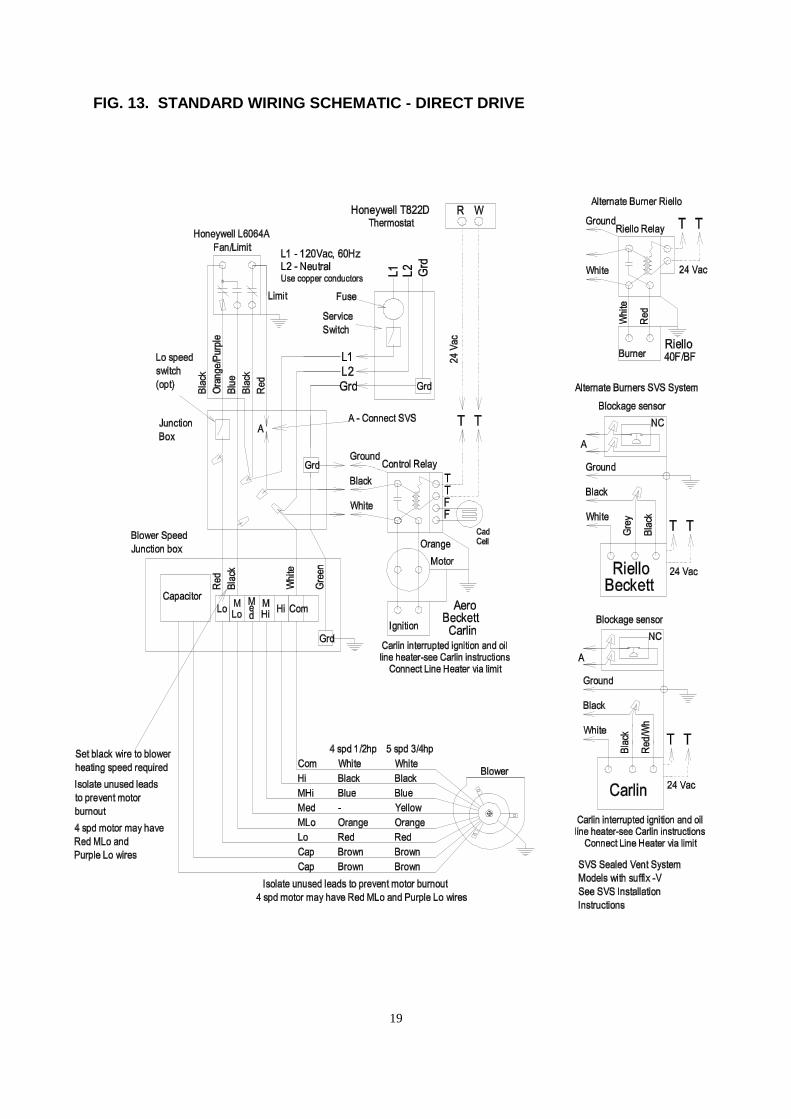
BLOWER ADJUSTMENTThis unit is designed for a maximum temperature rise through the furnace of 85o F at a maximum externalstatic pressure of 0.50 inches of water column. However, due to the wide range of static pressures in ductsystems, it is the responsibility of the installer to verify that the temperature rise does not exceed 85o F. Tomeasure the actual temperature rise let the unit operate for at least five minutes. Insert a thermometerand note the temperature of the warm air supply at a point at least 24 inches upstream from the heatexchanger surface. Next measure the temperature at the return air grill and take the difference. Airtemperature rise can be lowered by increasing the blower speed; lowering the firing rate; or increasingundersized supply and return air free area. The furnace will not operate properly and its life will bedecreased if insufficient air quantity passes over the heat exchanger. Similarly, too much air duringheating mode resulting in a temperature rise of less than 65o F may cause heat exchanger degradationdue to condensation.DIRECT DRIVE BLOWERThe installer should select the best speed tap for the specific installation. Recommended speed taps forheating are given in TABLES 1 (NH3) AND 3 (LFR) GENERAL INSTRUCTIONS. The motor RPM willvary over a range of static pressures. The blower heating speed can be changed by moving the black wireharness lead to another speed tap on the terminal block located inside the blower compartment. Refer toTABLES 2 (NH3) and 4 (LFR), BLOWER PERFORMANCE for airflow data. A second speed for non-heating modes can be selected using the red wire harness lead. See FIG. 13 and 14 for WIRINGSCHEMATICS.
BELT DRIVE BLOWER – NH3 onlyThe air delivery (CFM) and temperature can be varied by adjusting the motor pulley. Closing the pulleyincreases blower speed and decreases temperature rise. Opening the pulley decreases the blower speedand increases the temperature rise. A 6 inch diameter blower pulley is required for 0.20 inch w.c. staticpressure. A 5 inch diameter pulley is used for 0.20 inch w.c. static pressure. Correct belt tension allows a1 inch deflection midway between the pulleys. Too much tension will overload the motor—too little tensionwill cause slippage.
Pulley combinations vary according to the fuel input and duct static pressure. Recommended pulleycombinations for heating mode are given in TABLE 1 (NH3), GENERAL INSTRUCTIONS. Refer toTABLE 2 (NH3), BLOWER PERFORMANCE for air flow data.
An optional two-speed motor is available. The low speed can be used in non-heating mode. If the unit isnot factory wired for a two-speed motor, connect the red wire of the blower wire harness to the correctmotor lead. See FIG. 15 for STANDARD WIRING SCHEMATIC - BELT DRIVE and follow the motormanufacturer’s instructions. Make sure replacement and retrofit belt drive motors meet or exceed theOEM motor specifications. Two speed belt drive motors are available from Newmac.

14
MAINTENANCE & SERVICE
Maintenance and servicing must be done by a qualified burner technician or shortened furnace life andpoor efficiency may result. Under Tests and Observations and Requirements in CSA B139, the installer isrequired to perform tests to ensure proper and safe operating conditions. Newmac requires the installer tofill out the INSTALLER INFORMATION sheet found in this manual.
CLEANINGThe heat exchanger should be inspected on an annual basis. If cleaning is required, remove the cleanoutcover. Use a wire brush or cleaning tool (available from Newmac) to loosen scale and soot and a vacuumcleaner to remove it from the furnace. Replace gaskets if necessary before replacing the cleanout cover.A layer of soot on the heat exchanger surfaces and firetube walls will reduce heat transfer and canincrease fuel consumption significantly. A 1/32” layer of soot acts as an insulator and can result in a 3%increase in the amount of oil burned. A 1/16” layer may result in an average fuel loss of 8%.When removing the burner, cleanout or cover panels take care not to damage gaskets.NH3 FURNACE - take care not to break the combustion chamber. Removal of the combustion chamberplate assembly allows a more thorough inspection and cleaning.Replace all parts properly before starting the appliance.
WARRANTY
The following information is required to process warranty claims: owner’s name and address; furnaceserial number, model number, installation date; and installer’s name, address and phone number. A“Returned Goods Number” must be issued by Newmac prior to acceptance of returned goods. Refer tothe LIMITED LIFETIME WARRANTY for terms and conditions.

15
IMPORTANT HOMEOWNER INSTRUCTIONS
1. AN EMERGENCY POWER SWITCH IS REQUIRED TO BE INSTALLED IN ACONVENIENT LOCATION AT A SAFE DISTANCE FROM THE BURNER. THISSWITCH INTERRUPTS THE ELECTRICAL SUPPLY CIRCUIT TO THE APPLIANCE.MAKE SURE YOU ARE AWARE OF ITS LOCATION AND THE OFF POSITION ISCLEARLY MARKED.
2. KEEP THE SPACE CLEAR AROUND THE APPLIANCE WITHIN THE SPECIFIEDCLEARANCES TO COMBUSTIBLES.
3. ENSURE THE SUPPLY OF COMBUSTION AIR TO THE APPLIANCE IS NOTOBSTRUCTED OR CUT-OFF.
4. MAINTAIN PROPER VENTILATION OF THE APPLIANCE AREA.
5. MAINTAIN FREE AIR FLOW THROUGH THE RETURN AIR REGISTERS. *
6. CONTACT SERVICE PERSONNEL BEFORE REMODELLING.
7. CONTACT SERVICE PERSONNEL FOR ANNUAL SERVICE AND MAINTENANCE.
8. CONTACT SERVICE PERSONNEL FOR AIR FILTER REPLACEMENT. *
9. CONTACT SERVICE PERSONNEL BEFORE AND AFTER EXTENDED PERIODS OFAPPLIANCE INOPERATION.
10. THE BURNER IS FULLY AUTOMATIC IN OPERATION. ALL ADJUSTMENTSSHOULD BE MADE BY A QUALIFIED TECHNICIAN. DO NOT PUSH THE RESETBUTTON MORE THAN ONCE.
CAUTION : DO NOT ATTEMPT TO START THE BURNER WHEN EXCESS OIL HASACCUMULATED, WHEN THE APPLIANCE IS FULL OF VAPOUR, OR WHEN THECOMBUSTION CHAMBER IS VERY HOT.
11. CAUTION : DO NOT TAMPER WITH THE APPLIANCE OR CONTROLS—CALLYOUR SERVICE PERSONNEL.
12. DO NOT USE GASOLINE, CRANKCASE OIL, OR ANY OIL CONTAININGGASOLINE
13. ALWAYS KEEP THE OIL SUPPLY VALVE SHUT OFF IF THE BURNER IS SHUTDOWN FOR AN EXTENDED PERIOD OF TIME.
14. DO NOT START THE BURNER UNLESS THE BLOWER ACCESS DOOR ISSECURED IN PLACE.
15. NEVER BURN GARBAGE OR PAPER IN THE HEATING SYSTEM, AND NEVERLEAVE PAPER OR RAGS AROUND THE APPLIANCE.
* FURNACES ONLY

16
FIG. 10. TYPICAL OIL TANK PIPING INSTALLATIONS

17
FIG. 11. DIMENSIONS & CONTROL LOCATION – NH3

18
FIG. 12. LFR SET UP
19
FIG. 13. STANDARD WIRING SCHEMATIC - DIRECT DRIVE

20
FIG. 14. STANDARD WIRING SCHEMATIC - A/C READY DIRECT DRIVE

21
FIG. 15. STANDARD WIRING SCHEMATIC - BELT DRIVE

22
TABLE 6. DUCT SIZING FOR HEATING WITHOUT A/C COIL
Notes: 1. BTUH with maximum temperature rise.2. Gas furnaces are rated in input capacity. Rated output capacity is 80 % of input.3. Oil and electric furnaces are rated in output capacity.
TABLE 7. DUCT SIZING FOR HEATING & COOLING WITH A/C COIL IN DUCTAir conditioning systems should never be sized on the basis of floor area alone. Knowledge of the approximate floor area (sq. ft.)that can be cooled with a ton of air conditioning will be of invaluable assistance to you in avoiding serious mathematical errors.
BlowerMotor H.P.
Blower WheelDia. X Width
5"R
UN
S80
CF
M
6"R
UN
S11
5C
FM
7"R
UN
S15
5C
FM
31/
2x14
"17
0C
FM
1 1/2 ton18,000BTUH
600CFM
1/4 H.P.9" X 8"10" X 8"
16" X 8"or
12" round8 5 4 4
16" X 8"or
12" round24 " X 8"
2 ton24,000BTUH
800CFM
1/4 H.P.9" X 9"10" X 8"
22" X 8"or
14" round10 7 5 5
22" X 8"or
14" round22" X 12"
2 1/2 ton30,000BTUH
1000CFM
1/3 H.P.10" X 8"10" X 10"12" X 9"
20" X 10"or
16" round13 9 7 6
20" X 10"or
18" round30" X 12'
3 ton36,000BTUH
1200CFM
1/3 H.P.10" X 8"10" X 10"12" X 9"
24" X 10"or
18" round- 11 8 7
24" X 10"or
18" round30" X 12'
3 1/2 ton42,000BTUH
1400CFM
1/2 H.P. 3/4H.P.
10" X 8"10" X 10"12" X 9"12" X 10"
24" X 12"or
18" round- 12 9 8
24" X 12"or
18" round30" X 14"
4 ton48,000BTUH
1600CFM
1/2 H.P. 3/4H.P.
12" X 7"12" X 9"12" X 10"12" X 12"
32" X 10"or
20" round- 14 11 10
32" X 10"or
20" round30" X 18'
4 1/2 ton54,000BTUH
1800CFM
3/4 H.P.1 H.P.
12" X 8"12" X 9"12" X 10"12" X 12"
32" X 10"or
20" round- 16 12 11
32" X 12"or
22" round30" X 20'
5 ton2000CFM
3/4 H.P.1 H.P.
12" X 10"12" X 12"
32" X 10"or
20" round- 18 13 12 32" X 14" 30" X 22'
Min. Number Supply Runs@ 600 FPM Min. Return Duct
Size at Furnace or AirHandler
@ 800 FPM
Min. ReturnAir Grille Size(or equivalent)
@ Face Velocityof 500 FPM
Size ofO.D. Unit
SupplyDuct or
Extended Plenum@ 800 FPM
Normal AirFlow Req'd@ 400 CFM
per Ton
Furnace
5"R
UN
S80
CF
M
6"R
UN
S11
5C
FM
7"R
UN
S15
5C
FM
31/
2X
14"
170
CF
M
Return DuctFurnace orAir Handler@ 800 FPM
Return Air Grille(or equivalent)
@Face Velocityof 500 FPM
45,000to
55,000
500CFM
14" X 8"or
12" round100 7 5 4 3
14" X 8"or
12" round12" X 12"
60,000to
70,000
700CFM
18" X 8"or
14" round140 10 6 5 4
18" X 8"or
14" round24" X 10"
75,000to
85,000
800CFM
22" X 8"or
14" round170 10 7 5 5
22" X 8"or
14" round24" X 12"
95,000to
105,000
900CFM
24" X 8"or
15" round190 12 8 6 6
24" X 8"or
15" round24" X 12"
105,000to
115,000
1100CFM
22" X 10"or
16" round220 - 10 7 7
22" X 10"or
16" round30" X 12"
125,000to
150,000
1400CFM
24" X 12"or
18" round280 - 12 9 8
24" X 12"or
18" round30" X 14"
155,000to
160,000
1600CFM
1 - 35" X 10" or20" round or2 - 22" X 8"
360 - 14 10 1032" X 10"
or20" round
30" X 18"
165,000to
170,000
1800CFM
1 - 35" X 12"or
2 - 22" X 10"420 - 16 12 11 32" X 12" 30" X 20"
175,000to
190,000
2000CFM
1 - 35" X 14"or
2 - 22" X 12"480 - 18 13 12 32" X 14" 30" X 22"
Min. Number Supply Runs@600 FPM
MINIMUM SIZE
OUTPUTCAPACITY(See Notes)
Min. AirFlow Req'd.
Supply Duct orExtended Plenum
@ 800 FPM
Min. Sq. InchNeeded forSpec. CFM
(Total Area ofAll Supply Duct)

23
FIG. 16. NH3 EXPLODED ASSEMBLY

24
TABLE 8, NH3 PARTS LIST
ITEM PART NO. DESCRIPTION ITEM PART NO. DESCRIPTION
1 4110400 BASE PANEL 25 A TWO SPEED FAN & LIMIT
2 4110401 SIDE PANEL R.H. 2010024 HONEYWELL L6064A 1086B (8")
3 4110402 SIDE PANEL L.H. 25 B SINGLE SPEED FAN & LIMIT
4 4110403 REAR PANEL 2010025 HONEYWELL L4064B 2608 (8")
5 4110404 FAN PARTITION WHITE ROGERS E12(t)5D51-90 (8")
6 4110407 BURNER ACCESS PANEL 26 4110409 TOP PANEL
7 4110406 BLOWER ACCESS PANEL 27 4110180 TOP RAIL
8 4110405 FRONT PANEL 28 4120477 INSPECTION DOOR ASSEMBLY
9 2080054 FRONT PANEL GASKET 29 A 2110040 OIL BURNER - AERO HF-US-2X
10 4110408 CLEAN OUT PANEL 29 B 2110129 OIL BURNER - BECKETT AFG-AF60YHHS
11 4160201 HEAT EXCHANGER ASSEMBLY 29 C 2110033 OIL BURNER- CARLIN EZ-PRO
12 2080055 CLEANOUT COVER GASKET 29 D 2110031 OIL BURNER - RIELLO 40 F3
13 4060401 CLEANOUT COVER 29 E 2110032 OIL BURNER - RIELLO R35.3.05
14 4050115 BLOWER ELECTRICAL BOX ASSEMBLY 30 4110410 WIRE PANEL
15 4060402 COMBUSTION CHAMBER PLATE 31 4110412 FILTER RACK ASSEMBLY
16 2030008 COMBUSTION CHAMBER 32 2200010-2 48" BLOWER WIRE HARNESS (4 Wire)
17 4060403 COMBUSTION CHAMBER SUPPORT 2240034 FAN BELT - 1/2" X 34"
18 2080056 CHAMBER PLATE GASKET 2240035 FAN BELT - 1/2" X 35"
19 4110413 INSPECTION DOOR HOUSING 2240006 BLOWER PULLEY - 6" X 3/4"
20 2080007 INSPECTION DOOR GASKET 2240005 BLOWER PULLEY - 5" X 3/4"
21 A 2040114 DIRECT DRIVE BLOWER - DELHI G9-DD 33 41100140 BURNER CABLE (30" wire/18" conduit)
21 B DIRECT DRIVE BLOWER - TORIN - DC 916 916 5 34 2200101 4" X 4" JUNCTION BOX
21 C 2040115 DIRECT DRIVE BLOWER - DELHI - G10-8 DD 35 2200103 4" X 4" JUNCTION BOX COVER
21 D 2040145 DIRECT DRIVE BLOWER - DELHI - GT12-7 DD 36 3100341 SMOKE BAFFLE
21 E DIRECT DRIVE BLOWER - LAU - DD12-8AT 37 2180004 16" X 24" FILTER
4050117 1/2 hp, G9 DIRECT DRIVE BLOWER ASSEMBLY 2040019 5" DRAFT REGULATOR
2040113 BELT DRIVE BLOWER - DELHI G9 CLEAN OUT BRUSH
BELT DRIVE BLOWER - TORIN - BC 916 916 THERMOSTAT
4050105 1/2 hp, G9 BELT DRIVE BLOWER ASSEMBLY 2010001 HONEYWELL - T822D
22 A 2010040 5 uF 370 V CAPACITOR (used with 23 A & 23 B) 2010057 WHITE ROGERS - 1F30
22 B 10 uF 370 V CAPACITOR (used with 23 C) THERMOSTAT - HEATING/COOLING (optional)
22 C 2010052 20 uF 370 V CAPACITOR (used with 23 D) 2010027 HONEYWELL - T87F
23 A 2020007 1/3 hp DIRECT DRIVE BLOWER MOTOR (Emerson) 2010042 HONEYWELL SUBBASE - Q539A
23 B 2020008 1/2 hp DIRECT DRIVE BLOWER MOTOR (Emerson) HONEYWELL T8034 C
23 C 1/2 hp DIRECT DRIVE BLOWER MOTOR (A.O. Smith) 2200258 LOW SPEED ROCKER SWITCH (SPST, 15 AMP)
23 D 2020022 3/4 hp DIRECT DRIVE BLOWER MOTOR (A.O. Smith) FAN CENTER (optional)
BELLY BAND ASSEMBLY (includes band & arms) 2010059 WHITE RODGERS - 8A94-51 (DPDT for up to 3/4 hp)
2020003 1/2 hp BELT DRIVE BLOWER MOTOR 2010041 HONEYWELL - R8285A (SPDT for up to 1/2 hp)
2240001 3-1/4" X 1/2" VARIABLE SPEED PULLEY 2010015 HONEYWELL - R8405A (SPST for up to 1/2 hp)
24 4110414 FAN SLIDE HONEYWELL - R8405B (SPDT for up to 1/2 hp)

25
TABLE 9 LFR PARTS LIST
Item No. Part No. Description01 4110507 Base Panel02 4110503 Side Panel RH03 4110504 Side Panel LH04 4110506 Rear Panel05 4110505 Fan Partition06 4110517 Side Cover, Blower07 4110512 Front Blower Access Panel08 4110500 Front Panel09 4110515 Cleanout Cover Left Casing
010 4110514 Cleanout Cover Right Casing011 4160301 Heat Exchanger Assembly012 2080063 Cleanout Cover Gasket013 3100411 Cleanout Cover014 4110515 Breech Collar015 4110514 Breech Cover016 4120479 Inspection Door Assembly Complete017 4110509 Inspection Door Plate018 4110510 Inspection Door Support019 4110511 Inspection Port Cover020 2080065 Inspection Door Gasket021 2070018 Inspection Door Hinge Pin022 2220002 Torsion Spring023 3140122 Inspection Door Gasket Retainer Disk024 4060250 Smoke Pipe Assembly025 2080064 Smoke Pipe/Breech Gasket026 3100443 Breech Cover Plate027 4010310 Stainless Steel Baffle028 4050200 10” Direct Drive (DD) Blower Assembly027 4010310 Stainless Steel Baffle030 4050115 Blower Speed Junction Box Assembly
Item No. Part No. Description031 2010040 5uF 370v Capacitor032 2040116T GT10DD or DCT-1020-1020-5 Blower033 2020007 1/3HP 4 speed Direct Drive Motor034 4110502 Fan Slide, 10"035 2040114T G9DD, DC- or DCT-916-916-5 Blower039 4110501 Filter Rack Assembly040 2180007 20" x 25" Furnace Air Filter041 2200010-2 48" Blower Wire Harness042 2200101 4" x 4" Junction Box043 2200103 4" x 4" Junction Box Cover, switch type044 2200258 Low Speed Switch045 2010041 Honeywell R8258A Fan Center (optional)046 2080067 Front Casing Lower White Gasket047 2080116 Front Limit Control Yellow Insulation048 2010024 8" Fan/Limit Control, Honeywell L4064A1086B049 4050194 Fan and Limit Cable Set, 16"050 4050195 Burner Cable Set, 30"051 2010034 Riello Switching Relay, AL1008052 5400010 Oil Burner, Riello 40F3-6
052A 5400011PP Oil Burner, Riello BF3-6054 Cleaning tool
052B 2110147 Oil Burner, Beckett AFG70MM (NM701)052C 5400032 Oil Burner, Beckett Pre & Post AFG70MM (NM702)
052D 2110162 Oil Burner, Carlin EZ Pro052E 5400056 Oil Burner, Carlin Pre & Post EZ Pro

26
FIG 18 RIELLO BURNER MODEL 40 F3 & F5 EXPLODED ASSEMBLY
FIG 19 RIELLO BURNER MODEL 40 BF3 & BF5 EXPLODED ASSEMBLY
Item 2030016 Riello Burner End Cone Protector not shown. See Fig. 9 for its location.

27
TABLE 10 RIELLO BURNER PARTS LIST
ITEM PART NUMBER BURNER MODEL DESCRIPTIONF3 & F5 BF3 & BF5 RIELLO NEWMAC F3 F5 BF3 BF5
1 3006911 2090055 X X Hydraulic jack2 3006912 X X Capillary tube3 3000878 X X Hydraulic air shutter4 34 3005708 X X X X Fan5 33 3005844 2090041 X X X X Capacitor 12.5 uF6 3006993 X X Pipe connector-return7 3005847 X X 1/4" NPT/metric adapter-female8 3006992 X X Pipe connector-supply9 3006571 X X 3/8" NPT/metric adapter-male10 2 3007077 X X X X Crushable metal washer 3/8" ID11 4 3007028 X X X X O-ring - pump pressure regulator12 6 C7010002 2090043 X X X X O-ring - pump cover13 7 3005719 X X X X Pump screen14 8 3006036 X X X X Valve stem15 10 3007029 X X X X O-ring valve stem,upper16 11 3007156 X X X X O-ring valve stem,lower17 12 3007268 X X X X Nozzle outlet fitting18 14 3006553 X X X X Coil U-bracket retainer nut19 15 3002279 X X X X Coil20 16 3007802 2060007 X X X X Pump21 17 3000443 X X X X Pump drive key22 18 3005843 X X X X Motor23 9 3007203 X X X X Plate - valve stem retainer24 20 3002278 X X X X Primary control sub-base25 21 3001157 2010048 X X X X Primary control 530 SE/C26 22 3002280 2010045 X X X X Photo cell27 3005854 X X Semiflange (2 Req'd)28 24 3005855 X X X X Universal mounting flange29 25 3005856 2080058 X X X X Mounting gasket30 5 N/A X X Regulator31 19 3007315 X Air tube cover plate
3007316 X Air tube cover plate32 3007221 X Chassis front plate
3007222 X Air intake housing33 3007204 X X Manual Air Shutter34 32 3007207 X X Air intake housing
3007208 X Air intake housing32 3007824 X Air intake housing
35 3007232 X Burner back cover3007233 X Burner back cover
1 3008019 X Burner cover

28
TABLE 10 RIELLO BURNER PARTS LIST – continued
ITEM PART NUMBER BURNER MODEL DESCRIPTIONF3 & F5 BF3 & BF5 RIELLO NEWMAC F3 F5 BF3 BF5
1 3008023 X Burner Cover36 3007319 X Acoustic liner
3007320 X Acoustic liner37 13 3007087 X X X X Crushable metal washer 5/8" ID40 40 3948873 2210141 X X Short combustion head - 6"
40 3948973 2210143 X X Short combustion head - 6"41 41 3006968 X X Turbulator disc
41 3006977 X X Turbulator disc42 42 3006966 X X X X Electrode support43 43 3006965 X X X X Nozzle adapter44 44 3006969 X X Nozzle oil tube - short
44 3006973 X X Nozzle oil tube - short45 45 3006324 X X Regulator assembly - short
45 3006323 X X Regulator assembly - short46 46 3006330 X X Electrode assembly - short
46 3006329 X X Electrode assembly - short47 47 3005869 X X X X Electrode porcelain48 48 3007592 X X End cone assembly - short
48 3007594 X X End cone assembly - short3 3007568 X X Bleeder23 C5283000 X X Electrical fitting26 3008020 X Oil supply tube & adapter fitting26 3008024 X Oil supply tube & adapter fitting27 3007901 X X Plug29 3007630 X X Gasket burner cover30 3000681 X X Manual air damper regulator31 3008021 X X Air damper35 3007707 X X Cover screw and washer36 3007628 X X Filter assembly37 3007627 X X Plug-cover opening-burner reset
C7001025 2110172 X Two line conversion kitC7001026 2110173 X Two line conversion kit3007627 2010044 X X Relay, Honeywell R8038A 1048

29
FIG. 20. BECKETT BURNER MODEL AFG60YHHS EXPLODED ASSEMBLY
BECKETT BURNER MODEL AFG60HYYS PARTS LIST
PART NUMBERITEMNO.
BECKETT NEWMAC
BURNER MODELAFG60YHYS
NM504DESCRIPTION
1 5877 2090024 X Burner Housing Assembly2 3709 X Air Shutter3 3492 X Air Band4 3493 X Escutcheon Plate
5941 X Adjusting Plate Assy7 2456 2020012 X PSC Drive Motor, 3450 RPM9 2999 2090056 X Blower Wheel10 2454 2090011 X Flexible Coupling11 21844U 2060012 X Pump Clean Cut A2EA - 6520
51573 2090058 Suntec Pump c/w Soilenoid Valve12 2256 Pump Nozzle Port Fitting13 5636 Connector Tube Assembly14 2442 2090025 X Ignition Transformer (10,000 Volt)
51771U 2090064 X Electronic Ignitor (14,000 Volt)17 3708 2090044 X Low Firing Rate Baffle18 2090047 X 6" Electrode assembly21 5770 X Junction Box Kit26 3-666 X Knurled Locknut27 2-13 X Nozzle Adapter - Single28 1-49 X Electrode Clamp36 3384 X 3-3/8U Static Plate47 2110006 X Endcone , F3
31517 2110015 X Ceramic Heat Shield2110016 X Ceramic Heat Shield Holder
48 2090040 6" SS Air Tube c/w Welded Flange49 7456U 2010069 X Primary Relay, Honeywell R7184B
2090067 Primary Relay, Honeywell R7184P3416 2080051 X Flange Gasket51770 2090061 Field Controls AirBoot7006 2010006 X Cad Cell C554A1455B Honeywell
2100130 Nozzle, Delavan 0.65 X 70oA2100131 Nozzle, Delavan 0.75 X 70oA2100128 X Nozzle, Delavan 0.85 X 70oA2100132 Nozzle, Delavan 1.00 X 70oA2100140 Delavan Stop Drop (Pro Tek)

30
FIG. 21. AERO BURNER MODEL HF-US-2X EXPLODED ASSEMBLY
AERO BURNER MODEL HF-US-2X PARTS LIST
PART NUMBERITEMNO.
AERO NEWMAC
QTYREQ'D DESCRIPTION
1 35222100 2090016 1 HF-US Housing2 35040000 1 Blast Tube, 6"3 35161000 2090017 1 Mounting Flange - Fixed
26200005 1 Flange Spacer (Specify 5" Insertion & 6" Air Tube)4 2090013 1 Air Band, 3 Hole5 2020011 1 Motor 1/7 hp, 3450 rpm6 35152329 2090021 1 Fan, 508-229-HF-US-(S) SV7 35171223 2090011 1 Coupling8 2060004 2060004 1 Pump9 35382740 2090002 1 Transformer, 2721-456
Electronic Ignitor10 35141900 2110005 1 End Cone, AFC-2X
2090020 2 End Cone Screws, Stainless Steel12 2090030 1 Tube, Oil Delivery 5"19 35202202 4 Blast Tube Screw (specify length)25 35330000 1 Slide Plate26 35203901 1 Slide Plate Locking Screw27 35193201 1 Air Band Locking Nut28 1 Oil Line Assembly33 35182400 2080050 1 Oil Burner Mounting Gasket 1/8"100 1 Electrode Assembly
2010002 1 Primary Control, Honeywell R8184G2010006 1 CAD Cell, Honeywell C554A1455B

31
FIG. 22. CARLIN EZ-PRO EXPLODED ASSEMBLY
CARLIN EZ-PRO PARTS LIST
ITEMNO. PART NUMBER QTY
REQ'D DESCRIPTION
CARLIN NEWMAC EZ-PRO EZ-PRO PP1 77735 X X 7" Air Tube c/w Welded Flange2 98022 X X Motor, 1/6 hp, 3450 rpm3 X X Electrode Wire, Set of 24 X X Nozzle Line / Adapter Assembly5 41000SOCAS X X 14 kV Transformer / Ignitor
40200-02 X Primary Control, Interrupted Duty60200-02 X Primary Control, Interrupted Duty, pre & post purge
6 X Oil Valve ( in pump)7 22996 2060004 X Fuel Unit, Std. Single Stage, Suntec A2VA-71168 34397 X Oil Line, 3/16 OD, Std. Fuel Unit to Oil Valve9 34470 X Oil Line, 3/16 OD, Std. Fuel Unit to Nozzle Line10 75564 X X Coupling, For Std. Fuel Unit, Approx. 2-3/8" OAL11 77594 X Air Band12 77586 X Air Shutter13 81570 X X Head Positioning Bar Kit
4015300K X X Flame Detector81695 X X CAD Cell Assembly c/w Harness77933 X X Blower Wheel40212 X X Flange Gasket
2090063 X Field Controls AirBoot (Field Controls p/n 4626802)

32
FIGURE 23. COMMON CHIMNEY DRAFT PROBLEMS

33
FIGURE 24 TROUBLESHOOTING CHART
PROBLEM CAUSE CORRECTION
Check for Broken WiresTighten ConnectionsClean Contacts
Thermostat
Replace ThermostatBurner Motor Overload Tripped Press Rest ButtonCeased Pump Repair or Replace
Burner Motor Fails to Start
Faulty Primary Relay Repair or ReplaceOil Supply Check Oil SupplyAir Leak in Oil Supply Line Tighten Fittings or Replace LineOil Line Plugged or Kinked Clean or RepairOil Filter Clogged Replace or CleanLoss of Prime Eliminate Teed Oil LinesElectrode Setting Adjust ElectrodesLoose or Dirty Nozzle Replace NozzleIgnition Transformer Replace TransformerBurner Motor Overload Trips Press Rest ButtonCeased Pump Repair or Replace
Burner Start--No Flame
Faulty Primary Relay Repair or ReplaceCad Cell Clean or ReplaceOil Line Restricted Clear RestrictionPlugged Fuel Pump Clean StrainerLoss of Prime Eliminate Teed Oil Lines
Change to #1 OilCold OilConvert to One Line SystemAdjust Air Settings
Burner Locks out on Safety
Poor CombustionEnsure Draft is Adequate
Air Leak in Oil Supply Line Tighten Fittings or Replace LineLoose or Dirty Nozzle Replace NozzleFaulty Oil Pump Repair or Replace PumpOil Supply Line Ensure Properly DesignedLoss of Prime Eliminate Teed Oil LinesElectrode Setting Adjust ElectrodesCracked Electrodes Replace ElectrodesWrong Nozzle Use Specified NozzleLow Oil Pressure Adjust to Correct SettingExcess Air Adjust Air Setting
Burner Ignition Delayed
Faulty Transformer Replace TransformerInsufficient Combustion Air Provide Combustion AirInadequate Flue Draft Provide Specified DraftPump Seal Leaking Repair PumpLoss of Prime Eliminate Teed Oil LinesNozzle Assembly Adjustment Ensure Setting is CorrectBurner Adjustment Check Using InstrumentsBlast Tube Burned Off Check Blast TubeEnd Cone Wrong or Burned Off Check End ConeIncorrect Insertion Measure Insertion DepthDirty Burner Fan Clean BladesDamaged Chamber Check ChamberClogged Flue Passages Clean Flue PassagesNozzle After Drip Check Fuel Delivery System
Fumes & Odors From Burner
Unspecified Nozzle Replace Nozzle

34
FIG 24 TROUBLESHOOTING CHART – continued
PROBLEM CAUSE CORRECTION
Firing Rate Too Low Use Higher Input NozzleDirty Heat Exchanger Clean Heat ExchangerPoor Combustion Adjust Using InstrumentsUndersized Capacity Size Based on Heat LossDistribution System Ensure Proper Design
Not Enough Heat
Faulty Thermostat or Location Repair, Replace, or RelocateDefective Primary Control Repair or ReplaceFaulty Thermostat or Location Repair, Replace, or RelocateFaulty Oil Pump Check for Proper PressureFiring Rate Too High Reduce Nozzle SizeOversized Capacity Size Based on Heat Loss
Too Much Heat
Distribution System Proper Duct DesignPoor Combustion Adjust Using InstrumentsExcess Air Adjust Air SettingInadequate Flue Draft Provide Specified DraftInsufficient Combustion Air Provide Combustion AirOil Supply Check Oil SupplyElectrode Setting Adjust ElectrodesWrong Nozzle Use Specified NozzleFuel System Leaking Check Fuel System
Excessive Oil Consumption
Faulty Oil Pump Repair or Replace PumpOver-Firing Use Specified Nozzle Size
Replace Dirty FiltersIncrease Blower SpeedIncrease Undersized R/A DuctsClear Blocked Return RegistersIncrease Undersized S/A DuctsClear Blocked Supply GrillsReplace Faulty Blower MotorClean Clogged Blower Wheel
Tripping High Limit
Replace Broken Blower BeltFaulty Thermostat or Location Repair, Replace, or RelocateHeat Anticipator Set Too Low Adjust Heat Anticipator
Short Cycle
Defective Primary Relay Repair or Replace RelayBurner Pump Whine Eliminate Suction Line Air LeakDuct Expansion Stiffen Plenum & DuctsNoisePlenum Amplifies Noise Install Plenum ApronBlocked Flue Passages Clean BoilerUnspecified Burner Replace BurnerUnspecified Nozzle Install Correct NozzleIncorrect Head Install Correct HeadWrong/Misaligned Static Plate Install Correct Plate or AlignChimney Down Drafting Install Chimney Cap
Increase Draft at BreechPoor Over-Fire DraftCorrect Chimney ProblemsUse Specified NozzleOver-FiringUse Specified PressureUse Correct Air Tube Assembly
Burner Air Tube Burn-Off
Incorrect InsertionAdjust Flange
Reduced Draft Add Combustion AirDelayed Ignition Adjust Burner SettingsLoss of Prime Eliminate Teed Oil LinesUnspecified Burner Replace BurnerUnspecified Nozzle Install Correct Nozzle
Frequent Sooting
Incorrect Head Install Correct HeadReduce Motor SpeedPremature Corrosion Temperature Rise Too LowUse Higher Specified Nozzle

35
INSTALLER INFORMATION
NAME:
COMPANY:
INSTALLATION DATE:
THE HOMEOWNER SHOULD TELEPHONE ( ) FOR SERVICE OR
ADDITIONAL INFORMATION.
MODEL:
APPLIANCE INITIAL TEST AND SERVICE INFORMATION
1 FUEL INPUT (USGPH)
2 FUEL PRESSURE (PSIG)
3 FLUE PRESSURE (INCHES W.C.)
4 OVERFIRE PRESSURE (INCHES W.C.)
5 NOZZLE ANGLE / PATTERN
6 C02 PERCENT
7 BURNER MODEL
8 FLUE GAS TEMPERTURE (FO)
9 ROOM TEMPERTURE (FO)
10 SMOKE NUMBER (BACHARACH)
11 FUEL GRADE NUMBER
12 SUPPLY PLENUM STATIC PRESSURE (INCHES W.C.)
13 SUPPLY AIR TEMPERATURE (Fo)
14 RETURN AIR TEMPERATURE (Fo)
15 AIR TEMPERATURE RISE (Fo)
16 LIMIT CONTROL FUNCTIONING PROPERLY
17 PRIMARY CONTROL SHUT OFF TIME (IGNITION FAILURE)
18 PRIMARY CONTROL SHUT OFF TIME (FLAME FAILURE)

36
OIL FIRED FURNACE - LIMITED LIFETIME WARRANTY
Effective July 1, 1995 and subject to the following conditions Newmac Manufacturing Inc. warrants the Oil Fired Furnace, to the original owner purchaser, undernormal use and repair against defects in workmanship and materials for a period of one calendar year from the date of original installation. This warranty does not covernozzles, filters, belts etc.
The burner, blower, motors, controls or any other electrical or mechanical components not manufactured by Newmac are warranted for a period of one year fromdate of original installation by their respective manufacturers; burners 3 years.
Effective July 1, 1995 and on the date of original installation Newmac warrants to the original purchaser during his or her lifetime that the primary heat exchanger ofall Oil Fired Furnaces will be free from defects in material and workmanship provided however, this warranty shall apply only to the original installation of the furnacein a single dwelling unit used without interruption by the purchaser as his or her principal residence. This warranty does not apply to solid fuel or combination furnacesand is subject to the conditions and exceptions of warranty listed below.
Under the above warranty Newmac Mfg. at its option will repair or replace the heat exchanger under the above terms or offer the then current applicable retail priceof a heat exchanger towards a new equivalent furnace. Proof of original purchase will be required.
The warranty must be registered within 30 days of installation or the following pro-rated warranty “Twenty Year Warranty” applies.Where the owner of the dwelling is not the original purchaser and in multi-family dwellings Newmac warrants the primary heat exchanger against defects in materials
and workmanship under a 20 year Limited Warranty subject to the conditions and exceptions listed below and on a prorated basis as follows of the then current retailprice
0-10 Years 100% Warranty 0 of Retail Price11-12 " 50% " 50% "12-14 " 40% " 60% "14-16 " 30% " 70% "16-18 " 20% " 80% "18-20 " 10% " 90% "20 years and over 0% " 100% "
The purchaser must pay all other costs of warranty service including labour costs involving diagnostic calls and or removing, servicing and or replacing warrantyparts and or warehousing charges and or freight costs. All parts are supplied F.O.B. Debert, Nova Scotia and the defective parts must be returned freight prepaid forrepair and or warranty consideration when requested by Newmac Mfg.CONDITIONSThis warranty refers to the primary combustion heat exchanger.In order for this warranty to be effective:1. The furnace must be installed by a qualified licensed installer and in accordance with Newmac’s installation instructions. The furnace must also be installed inaccordance with all applicable, local states, or provincial codes and the National Warm Air Heating and Air Conditioning Association Standards or generally acceptedequivalent standards.2. The Furnace must operate in an environment not contaminated by halogens (such as but not limited to fluorine or chlorine) or chlorinated hydro carbons. Thesecorrosive chemicals entering the combustion area cause rapid deterioration of inner surfaces leading to heat exchanger failures. The furnace must be maintained andcleaned on an annual basis by qualified personnel; air filters should be changed monthly. Oil filters and nozzles must be changed annually.3. The furnace must be sized and fired correctly as stated on the label for the residence. The label must not have been defaced or removed.4. The furnace must not be modified from its published design or purpose and or an air conditioning coil shall not be installed on the return air side of the furnace.5. Furnace must not have been removed from the original installation site.6. There must be adequate return air and or ductwork.7. There must be adequate combustion air installed to the furnace room; and in the case of sidewall venting there must be adequate ventilation air in addition tocombustion air to prevent depressurization of the home.8. Warranty components may be replaced with reconditioned parts at the discretion of Newmac Mfg.9. Proof of original purchase will be requested under this warranty.EXCEPTIONS1. All labour, freight or diagnostic calls, removal and replacement costs and warehousing charges are the responsibility of the purchaser including the return to Debert,Nova Scotia of defective parts.2. Defects or damages caused by failure of the refractory chamber, improper installation, wiring, electrical current characteristics, accident, misuse or abuse, fire, flood,alteration and or misapplication of the product, default or delay in performance; caused by war, government restrictions, restraints, strikes, material or freezing.3. Refractory chamber, nozzles, air filters, belts etc...4. Defects or damages caused by nozzle failure and/or plugging and/or oil flow restrictions due to cold oil from outside tanks or misalignment of burner at installation.5. This warranty in no way can be considered as a guarantee of workmanship of an installer connected with the installation of the Newmac Oil Fired Furnace or asimposing on Newmac any liability of any nature for unsatisfactory performance as a result of faulty workmanship in the installation which liability is expresslydisclaimed.6. This warranty will not be applicable if the furnace is damaged or a result of being improperly serviced or operated.LIMITATIONS ON WARRANTYNewmac will make no express warranties other than the warranty set forth above. All implied warranties including the implied warranties of amerchantability and fitness for a particular purpose are limited to the duration of the express warranty, set forth above. Liabilities for incidental andconsequential damages are excluded regardless of the cause. Some provinces in Canada and some states in the U.S.A. do not allow limitations on howlong an implied warranty lasts so the above may not apply to you. The expressed warranties made in this warranty are exclusive and may not be altered,enlarged or changed by any distributor, dealer or any other person whatsoever. All replacement parts whether new or remanufactured, assume as theirwarranty period on the remaining period of this warranty.For routine service requirements contact the dealer who installed the equipment originally, or an alternate qualified and registered heating dealer or electrical.
To register your warranty, please complete form below, detach and mail to Newmac Mfg. Inc. P.O. Box 9, Lancaster Cr; Debert, N.S. B0M 1G0
LIMITED LIFETIME WARRANTY REGISTRATION
_ _ _ _ _ _ _ _ _ _ _ _ _ _ _ _ _ _ _ _ _ _ _ _ _ _ _ _ _ _ _ _ _ _ _ _ _ _ _ _ _ _ _ _ _ _ _ _ _ _ _ _ _ _ _ _ _ _ _ _ _ _ _ _ _ _ _ _ _ _ _ _ _ _ _ _ _ _Owner’s Name Date of Installation
_ _ _ _ _ _ _ _ _ _ _ _ _ _ _ _ _ _ _ _ _ _ _ _ _ _ _ _ _ _ _ _ _ _ _ _ _ _ _ _ _ _ _ _ _ _ _ _ _ _ _ _ _ _ _ _ _ _ _ _ _ _ _ _ _ _ _ _ _ _ _ _ _ _ _ _ _ _ _ _Address of Installation
_ _ _ _ _ _ _ _ _ _ _ _ _ _ _ _ _ _ _ _ _ _ _ _ _ _ _ _ _ _ _ _ _ _ _ _ _ _ _ _ _ _ _ _ _ _ _ _ _ _ _ _ _ _ _ _ _ _ _ _ _ _ _ _ _ _ _ _ _ _ _ _ _ _ _ _ _ _ _Dealer’s Name Dealer’s Address
_ _ _ _ _ _ _ _ _ _ _ _ _ _ _ _ _ _ _ _ _ _ _ _ _ _ _ _ _ _ _ _ _ _ _ _ _ _ _ _ _ _ _ _ _ _ _ _ _ _ __ _ _ _ _ _ _ _ _ _ _ _ _ _ _ _ _ _ _ _ _ _ _ _ _ _ _ _ _Furnace Serial Number Furnace Model Number